1
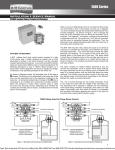
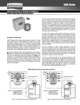
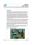
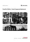
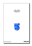
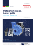
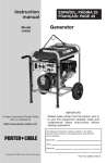
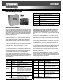
5200 Series
INSTALLATION & SERVICE MANUAL
5200 Solid State Relays
Basic Specifications
Dual Voltage
Contacts
Contact Ratings
Arrangement
Power Required
Operating Temp.
Low Energy
Sensing Circuit
PRINCIPLE OF OPERATION
B/W 5200 Solid State Controls are offered in two basic types for use in a wide
range of low and high sensitivity applications. Both are designed to operate
on either 115 or 230 volts AC at 50/60 hertz. Both incorporate a low voltage
sensing circuit. Both are also capable of performing control functions directly
from electrodes suspended in a well or tank, the B/W Unifloat level sensing
system, or various pilot devices such as pressure, flow and limit switches,
thermostats and pushbuttons, etc.
In addition, their operating characteristics are virtually unaffected by ambient
temperatures ranging from -40°F to +180°F, or by variations from 80% to
110% of their rated voltage. Both controls are also furnished with a complete
set of R1 fixed sensitivity resistors or a variable resistance potentiometer
to permit adjustment of operation based on the resistance of the liquid or
material to be controlled. See tables below.
5200-LF1 Low Sensitivity Control
The basic components of this control are a transformer, a circuit board with
voltage divider circuit, a silicon controlled rectifier (SCR), and a load to provide
isolated DPDT contacts. The sensing circuit voltage is 8.0 volts ac.
5200-HF2 High Sensitivity Control
This control is similar to the 5200-LF1, but with two basic differences: First, a
rectifier is used to convert the sensing circuit voltage from ac to 9.6 volts dc;
second, a field effect transistor (FET) is added to provide higher sensitivity.
This permits positive operation on liquids with very high resistance.
Since the voltage divider circuit compares the liquid resistance to the R1
sensitivity resistor on both 5200-LF1 and 5200-HF2 controls it is important that
the R1 resistor selected be rated higher than the resistance of the liquid or
other sensing circuit.
5200-LF1 Low Sensitivity Control
Maximum Lead Application
Wire Lengths*
Recommondations
15,000 feet
All metallic circuits, B/W Controls Unifloat
15,000 feet
Strong electrolytes: Plating solutions.
15,000 feet
Weak eletrolytes: Ammonium hydroxide, borax,
acetic acid
1,800 ohms
11,000 feet
Most food processing applications: Beer wine,
fruit juices,milk buttermilk
3,900 ohms
5,000 feet
Highly corrosive acid or caustic solutions where
electrode current must be minimized to extend
electrode life: Hydrochloric acid, sulfuric acid,
etc
10,000 ohms
2,000 feet
Ordinary water with medium to high mineral
content, sewage, water soluble oil and starch
solutions.
22,000 ohms
900 feet
Sugar syrup solutions, most water with low
mineral content. (Soft water-not distilled or
deionized water. Use 5200-HF2 Control)
*Distance shown in the tables above are based upon the use of
two 18-gauge lead wires installed in 1/2” diameter conduit.
R1 Sensitivity
Resistor
270 ohms
470 ohms
1,000 ohms
Either 115 or 230 volts AC at 50/60 hertz
Silver Cadmium Oxide
10 amperes at 120 or 240 volts AC or 28 volts DC,
1/4 hp at 120 volts AC. and 1/3 hp at 240 volts AC
Double pole, double throw load contacts plus single pole,
doublethrow holding circuit contacts
9 volt-ampere, 6 watt
-40°F to 180°F
AC - 8 volts (less than 30 milliamperes) for 5200-L,
DC - 9.6 volts (less than 1 milliampere) for 5200-H
Direct Operation
In direct operation, the load relay is energized when the level sensing
circuit is completed. When operating from electrodes for pump down
operation, and liquid is below lower electrode, a high resistance is sensed
across terminals 13 & 14, and a negative, or out-of-phase, signal is fed to the
SCR.
When liquid rises to touch the upper electrode, a low resistance is sensed
across terminals 13 & 14, and the signal to the SCR becomes positive, or
in-phase, turning the SCR on, which, in turn, energizes the load relay to start
the pump.
When load relay is energized, the holding circuit contact (4-7) closes to hold
in the relay through the lower electrode and the liquid resistance until liquid
level falls below the lower, or pump stop, electrode, at which time the SCR
turns off and de-energizes the load relay to stop the pump.
Inverse Operation
In inverse operation, load relay is de-energized when the level sensing circuit
is completed. In this mode of operation, function of load relay is reversed.
When operating from electrodes for pump up operation, and liquid is below
lower electrode, a positive, or in-phase, signal turns the SCR on, energizing
the load relay to start the pump.
When liquid rises to touch the upper electrode, a negative, or out-of-phase,
signal turns the SCR off, de-energizing the load relay and stopping the pump.
The holding circuit contact (1-7) closes, keeping the load relay de-energized
until the liquid again falls below lower electrode.
5200-HF2 High Sensitivity Control
Maximum Lead Application
Wire Lengths*
Recommondations
50,000 feet
Ordinary water with medium to highmineral
content, sewage, water soluble oil and starch
solutions, long distance applications
22,000 ohms
50,000 feet
Water with low mineral content (soft - not
distilled or demineralized), sugar syrup
solutions, long distance applications.
68,000 ohms
50,000 feet
Steam condensate, corn syrup, strong alcohol
solutions up to 50%
330,000 ohms 50,000 feet
Alcohol solutions up to 70%
820,000 ohms 35,000 feet
Deionized or distilled water, 95% glycerine, 90%
hydrogen peroxide, 95% ethyl alcohol, granular
solids with high moisture content
2.2 megohms
12,000 feet
Glacial acetic acid, acetone, granular solids with
some moisture content
5.6 megohms
4,000 feet
M.E.K. (Methyl ethyl ketone)
12.0 megohms 2,000 feet
Anhydrous ammonia
NOTE: DI water, glycols, alcohols and granular solids may require the 2.2, 5.6
or 12.0 megohms R1 resistor depending upon their purity or moisture content.
R1 Sensitivity
Resistor
10,000 ohms
INSTALLATION INSTRUCTIONS
These instructions relate primarily to the B/W electrode system of liquid level
sensing. Call 1-800-635-0289 to request the B/W Catalog (Z66) for complete
specifications, wiring and electrode equipment, etc.
ELECTRODE LEAD WIRES
Shielded cable is not required. Generally the size of the wire used is passed
upon the physical strength required to meet given installation condition. Size
14 to 18 gauge wire is generally strong enough for private buried or overhead
wiring, although size 26 gauge wire is adequate for positive relay operation.
In some long distance applications, communication cable or telephone circuits
may be used. In all cases, however, control circuit wires must have good
insulation, and splices or connections must be watertight and insulated from
ground.
Special Note - In order to prevent feed-back which can cause faulty
operation, electrode lead wires should not be run in the same conduit
with power or load carrying circuits.
ELECTRODE LEAD WIRE LENGTH
5200-LF1 Low Sensitivity Control
These controls operate with 8 volts ac on the sensing circuit, and in general,
the maximum lead length is determined by the capacitance of the lead wires
and the value of the R1 sensitivity resistor. Refer to Table on page 1 for
suggested maximum lead lengths.
5200-HF2 High Sensitivity Controls
These controls operate with 9.6 volts dc on the sensing circuit, and in general,
the maximum lead length is determined by the resistance of the lead wires.
These controls will operate reliably with electrode lead lengths of several
miles, but it is important to select the correct R1 sensitivity resistor to assure
positive operation over these extreme distances. Refer to Table on page 1
for suggested maximum lead lengths. If your application involves greater
distances than those shown, please contact factory.
GROUND CONNECTIONS
In all installations using electrodes, a good external ground connection and
a dependable return circuit to the liquid are required. In most instances,
grounding to a metal pipe leading to the tank is suitable, but electrical conduit
should not be used for this purpose.
If a good ground connection to the liquid is not available, an additional
ground or common electrode is required. When used, the ground or common
electrode should extend slightly below the longest operating electrode. In
addition, it is also desirable to ground the control chassis directly to the ground
terminal or through a mounting screw.
If PVC well casings or drop pipes are used to contain the electrodes, a ground
or common electrode is required.
R1 SENSITIVITY RESISTORS
Both the high sensitivity and the low sensitivity controls are shipped from
the factory with a complete set of fixed resistors or with a variable resistance
potentiometer. Variable resistance potentiometers are furnished in three
different ranges according to the table which follows.
Relay Type
5200-LF1
5200-LV1
5200-LV2
5200-HF2
5200-HV3
5200-HV4
5200-HV5
Sensitivity Ranges
R1 Resistor Direct Operation
Inverse Operation
Fixed R1
Up to 16,000 ohms
Up to 26,000 ohms
Resistor
Variable
100 to 700 ohms
200 to 1,200 ohms
Variable
600 to 15,000 ohms
1,000 to 24,000 ohms
Fixed R1
Up to 11.6 megohms
Up to 12.0 megohms
Resistor
Variable
2,000 to 100,000 ohms 2,000 to 100,000 ohms
Variable
.007 to 1.0 megohms
.007 to 1.0 megohms
Variable
.047 to 5.0 megohms
.047 to 5.0 megohms
To determine which fixed sensitivity resistor to install, please refer to the
table which follows. When operating from electrodes, select a resistor having
a sensitivity value greater than the specific resistance of the material to be
controlled. Any of the resistors can be used when operating from switch
contacts, but the smallest value is recommended. Fixed resistance R1
resistors should be installed as shown on the wiring diagram furnished with
the control.
2
Fixed Resistor Sensitivity
5200-LF1 Sensitivity Control
Part Number
Nominal Resistance
04-154900
270 ohms
04-155000
470 ohms
04-138300
1,000 ohms
04-155100
1,800 ohms
04-155200
3,900 ohms
04-149400
10,000 ohms
04-138400
22,000 ohms
5200-HF2 High Sensitivity Control
Part Number Nominal Resistance
04-149400
10,000 ohms
04-138400
22,000 ohms
04-138500
68,000 ohms
04-138600
330,000 ohms
04-138800
.007 to 1.0 megohms
04-138900
820,000 ohms
04-139000
2.2 megohms
04-139100
5.6 megohms
SERVICE INSTRUCTIONS
B/W Solid state controls are designed and built to require a minimum of
service in the field. Each one is tested at the factory to insure positive
operation, and should not be altered or tampered with prior to installation.
If a control does not operate properly after it has been installed with the
proper sensitivity resistor added, the following information will be helpful in
determining the probable cause.
Direct Operation
In direct operation, the load relay is energized when the liquid reaches the
upper electrode or Unifloat reed switch level, and electrode current is flowing.
Be sure sensitivity resistor has been installed between terminals 14 and 15,
and a good ground connected to terminal 13.
!#,INE
6OR6
OR(Z
6
#HASSIS'ROUND
4HROUGH-OUNTING3CREW
6
3ENSITIVITY
2ESISTOR
,OAD
#ONTACTS
3%2)%3
2%,!9
2
'ROUNDRETURNTOTANK
ORELECTRODEIFREQUIRED
%,%#42/$%
(/,$%2
4/05-0
34!24%2
6!2)!",%
2%3)34!.#%
0/4%.4)/-%4%2
/04)/.!,!4
%842!#/34
05-034!243
05-034/03
4!.+
PUMP DOWN
A - Load Relay Will Not Pull In
1. Power Failure or No Voltage at AC Line Terminals
Voltage at power in-put terminals should be 115 volts ac between terminals 10
& 11 or 230 volts ac between terminals 10 & 12.
2. Defective Control
To check control, disconnect electrode and load connections from control
terminals. Apply line voltage to the appropriate terminals (10-11) or (10-12),
and touch terminals 13 and 14 with an insulated jumper wire. Load relay
should pull in when the jumper is connected, and drop out when the jumper is
removed. Failure to do so indicates a defective control.
3. Poor Ground Connection
Controls will not function unless a good dependable ground connection is
made to terminal 13. If a load relay does not pull in when liquid contacts
the upper electrode, check ground connection to be sure it complies with
installation instructions.
4. Broken Wires
A broken or loose wire from the control to the upper electrode or the ground
(common electrode) will prevent load relay from pulling in. Broken wires can
be checked by shorting the upper electrode to ground, or to the common
electrode if used, at the electrode holder. If relay fails to pull in, one or both of
the electrode leads is open. The individual leads can be checked by running
temporary wires from the control to the electrode holder outside of conduit.
If the load relay now pulls in, when shorting electrodes as noted above, the
break is between the control and electrode holder. If load relay pulls in when
the leads are shorted with a jumper at holder, but not at electrode tips, the
break is in the electrode suspension wire.
5. Sensitivity Resistor Too Low
If the sensitivity resistor value is too low for the resistance or conductivity of the liquid
to be controlled, the load relay will not pull in, or it will buzz and chatter before pulling
in. In either case, the sensitivity resistor should be replaced with a higher value
resistor (see table, page 2). If in doubt about R1 resistor selection, furnish factory
with details on liquid, or send sample of liquid for testing.
6. Fouled Electrodes
Accumulation of dirt, oil, grease, or other deposits on the electrodes may insulate
them and prevent load relay from pulling in. If this occurs, the electrodes should be
inspected and cleaned at regular intervals, as required, to eliminate the difficulty.
If unusual quantities of oil, grease or sludge are encountered, the electrodes can
be mounted inside a pipe that is flushed with clean water. A 4” pipe should be used
-- with the bottom located below the lowest expected water level, and vent holes
provided at the top so that the level inside and outside the pipe will be the same. A
small flow of water entering the top of the pipe will cause an outward flow of water
from the bottom of the pipe and prevent undesirable material from entering. Thus,
the electrodes have a clear surface on which to operate, and will stay clean.
7. Electrodes Too Short
It is possible for an installation to be completed in which the upper electrode is
suspended at a point where the liquid cannot make contact. All installations should,
of course, be checked to make sure that the proper electrode lengths are provided. If
stand pipes are used, make sure pipe is vented above upper electrode setting.
B - One Level Operation
If control operates at one level only (starts and stops at one electrode level) check
following:
1. Electrode Wires
If wires between control and electrodes are interchanged, load relay will not operate
over a range in level, but from the lower electrode only. To correct, simply reverse
electrode connections either at terminal strip or electrode holder.
2. Holding Circuit
If the holding circuit (terminals 4--7) is not closing, the load relay will operate from the
upper electrode only. If the holding circuit is not opening, the relay will operate from
the lower electrode only. This holding circuit contact can be checked for continuity
with an ohmmeter. If defective, and if contacts 2-5-8 are not being used for load
connections, contacts 5-8 can be used as a holding circuit contact. Move the internal
jumper from terminal 7 to terminal 8, and move the lower electrode connection from
terminal 4 to terminal 5.
If the load relay does not pull in , short the relay with a piece of insulated wire by
bridging between relay terminals 13 & 14. The load relay should pull in when this
connection is broken. If the relay does not drop out, a short to ground is indicated
in the lower electrode lead between the control and electrode holder. If any of these
conditions exist, disconnect the power and replace the grounded wires.
3. Electrode Holder
Excessive dirt or moisture over the insulation at the electrode holder or the
electrodes can cause faulty operation. The interior of the electrode holder and its
underside should be kept clean and dry. Conduit connection should be made so that
no condensation can enter the holder. The underside of vertically mounted holders
should never come in contact with the liquid. Insulated rod electrodes should be
used with horizontally mounted holders. Electrodes should be kept clean and free
of dirt or grease. A periodic check should be made to make sure that they do not
become fouled with floating debris or insulating deposits.
4. Length of Electrode Lead Wire
On installations with excessive distance (over 1,000 feet) between a 5200-LF1 low
sensitivity control and the tank, capacitance in the lead wires from the control to the
electrodes may affect normal operation. If wired for direct operation, capacitance
would cause the load relay to hold in when the liquid leaves the lower electrode. If
wired for inverse operation, the load relay would fail to pull in. In this event, a 5200HF2 high sensitivity control should be used.
Inverse Operation
In inverse operation, the relay is energized when liquid falls below the lower
electrode, and current ceases to flow. Be sure sensitivity resistor has been installed
between terminals 13 & 14, and a ground connected to terminal 15.
!#,INE
6OR6
OR(Z
6
#HASSIS'ROUND
4HROUGH-OUNTING3CREW
6
3ENSITIVITY
2ESISTOR
2
'ROUNDRETURNTOTANK
ORELECTRODEIFREQUIRED
2. Check for physical vibration caused by contactors or magnetic starters
mounted nearby.
3. Check A-4 & A-6.
D - Constant Chatter
If load relay contacts chatter continuously, check defective control as in A-2.
1. If relay now operates correctly, check A-4 & A-6, B; C-1 and C-2.
2. If relay still chatters with terminals 13 & 14 jumpered together, the load relay
is defective, or the capacitor across the load relay coil may be defective.
E - Load Relay Will Not Drop Out
If relay will not drop out when liquid falls below lower electrode, check the following
points:
1. Defective Control - See A-2.
2. Grounded Electrode Leads
A ground in the lead wire to the upper or lower electrode will prevent the relay from
dropping out on low liquid level.
If the distance from the holder to the control is relatively short, the best way to check
for ground is to connect replacement wires from the terminal strip to electrode holder,
outside of conduit, and test for proper operation. If load relay drops out properly, it is
safe to assume that a ground exists in the original wires to the electrode holder.
If control is located a considerable distance from the electrode holder, check for
ground as follows: Disconnect power, remove wires from terminals in electrode
holder, and allow them to stick up in the air to eliminate the possibility of contacting
a grounded part. Then turn on power. If load relay pulls in, a short is indicated in the
upper lead wire to ground between the control and the electrode holder.
%,%#42/$%
(/,$%2
C - Intermittent Operation
If the control occasionally short cycles or operates intermittently, check the following:
1. Continuously monitor input voltage for fluctuations or voltage spikes.
,OAD
#ONTACTS
3%2)%3
2%,!9
4/05-0
34!24%2
6!2)!",%
2%3)34!.#%
0/4%.4)/-%4%2
/04)/.!,!4
%842!#/34
05-034/03
05-034!243
4!.+
PUMP UP
F - Load Relay Will Not Pull In
If relay will not pull in when liquid drops below lower electrode, failure to operate is
probably caused by one of the following conditions:
1. Power Failure or No Voltage
See Section A-1 under Direct Operation.
2. Defective Controls
To check the relay, disconnect electrode and load connections from relay terminals.
Apply line voltage to the appropriate terminals, (10 & 11 or 10 & 12), and short
between terminals 14 & 15 with an insulated jumper wire. The load relay should drop
out when the jumper is connected and pull in when the jumper is removed. Failure to
do so indicates a defective control.
3. Grounded Electrode Leads
A ground in the lead wire to the upper or lower electrode will prevent the load relay
from pulling in . Section E-2 describes how to isolate the grounded wire when the
relay is being used for direct operation. This same method can be used when the
control is being used for inverse operation, but the functions must be reversed. (i.e.
“drop out” interchanged with “pull in”). In section E-2, bridge between terminals 14 &
15 instead of 13 & 14.
4. Electrode Holder - See Section E-3
5. Length of Lead Wires
Excessive distance will not allow the 5200-LF1 low sensitivity control to operate
when the liquid drops below the lower electrode. See Section E-4.
3
G - One Level Operation
If load relay operates at one level only (starts and stops at one electrode), check
following:
1. Electrode Wires - See Section B-1.
2. Holding Circuit
If the holding circuit (contacts 1-7) is not opening, the load relay will operate from
the lower electrode only. If holding circuit is not closing, the relay will operate from
the upper electrode only. As in Section B-2 for direct operation, if contact 1-7 is
defective, contacts 2-8 can be used as an alternate holding circuit contact.
H - Intermittent Operation
If load relay occasionally short cycles or operates intermittently, check the
following:
1. See Section C-1 and C-2.
TEST CIRCUIT BOARD AND LOAD RELAY
Direct Operation
Test the control as in A-2 with jumper between terminals 13 & 14. If load relay
does not pull in, check on circuit board between two black wires leading from
load relay for a reading of 22 to 26 volts dc. If the voltage reading is low, the
circuit board is defective. If the voltage reading is high (39 to 44 volts dc), the
load relay has an open coil.
Inverse Operation
Test the control as in F-2 with jumper removed. If load relay does not pull
in, check as above for 22 to 26 volts dc. If voltage is low, circuit board is
defective. If voltage is high (39 to 44 volts dc), load relay has an open coil.
Replace the circuit board or the load relay as required. See parts list for
details. If a competent technician is not available, the control should be
returned to factory for repair or replacement.
2. Check Section J-3 and J-5.
I - Constant Chatter
If load relay chatters continuously, check as in Section F-2. If relay now operates
correctly, check Sections J-3 & J-5, G, and H.
5200 RELAY CHASSIS DIMENSIONS
If load relay still chatters with terminals 14 & 15 disconnected, the relay is
defective or there is a defective capacitor in the circuit board.
J - Load Relay Will Not Drop Out
If the relay will not drop out when the liquid touches upper electrode, check the
following:
1. Defective Control - See F-2.
2. Poor Ground Connections
A good dependable ground connection should be made to terminal 15 to complete
the circuit back to terminal 14 as indicated in Section A-3.
3. Broken Wires
A broken or loose wire from the control to upper electrode or ground (common
electrode) will prevent load relay from dropping out. Check as in Section A-4, but
“pull in” should be replaced with “drop out” in the description.
4. Sensitivity Resistor Too Low
If the sensitivity is too low, the load relay will not drop out, or will buzz and chatter.
See A-5, but “pull in” should be replaced by “drop out”.
5. Fouled Electrodes
Accumulated deposits on the electrodes will insulate them, and prevent
the load relay from dropping out. See Section A-6.
6. Electrodes Too Short - See Section A-7.
CONTROL REPAIRS
All B/W controls are tested at the factory prior to shipment to insure proper
operation. They should be handled with care during installation to avoid breaking
electrical connections. If the control does not operate properly after it has been
installed, and service instructions indicate a defect, repair should be attempted
only by an experienced electronic technician as follows:
CHECK TRANSFORMER
With the ac line voltage applied to terminals 10 & 11 or 10 & 12 as shown on
Form 448, the following voltages should be read between the transformer wire
connections on back of the control (±15%):
Black to Orange ..........................115 volts
Black to Blue.............................. 230 volts
Red to White ............................... 3.6 volts
Red to Brown .............................. 7.2 volts
Brown to White ........................... 3.6 volts
Green to Yellow ........................... 30 volts
If these out-put voltages are not present, and in-put voltages check, the
transformer is defective and should be replaced.
Replacement Parts for 5200 Solid State Controls
Description
Part Number
Resistor Set - Low
52-110105
Resistor Set - High
52-120105
*Potentiometer Kits for 5200-LV
Range LV1
52-110205
Range LV2
52-110206
*Potentiometer Kits for 5200-HV
Range HV3
52-120205
Range HV4
52-120206
Range HV5
52-120207
Circuit Board - Low
52-110114
Circuit Board - High
52-120114
Transformer
52-110106
Load Relay
04-261900
Terminal Block - Line
04-281900
Terminal Block - Probe
04-281800
*See Sensitivity Range table shown on page 2.
Copyright 2007 by AMETEK Automation & Process Technologies
1080 N. Crooks Road, Clawson, MI 48017 Toll Free 800-635-0289
Phone 248-435-0700 Fax 248-435-8120 www.ametekapt.com
432
5200.M4R
5/07.Z152