1
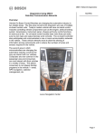
Diagnosing
Networks
Also Inside:
Driver Seat Diagnostics
Prepare to Pass
Out of Juice
Vintage Sports Cars
www.mastertechmag.com | April 2010 1
*Details available at your authorized BMW center.
2 Master Technician Online | www.mastertechmag.com
Original BMW Parts
www.bmwusa.com
The Ultimate
Driving Machine®
www.mastertechmag.com | April 2010 3
4 Master Technician Online | www.mastertechmag.com
Contents
Feature Stories
20Driver Seat Diagnostics
by John Anello
Our man John stays clean and comfortable
while doing a successful diagnosis.
30Prepare to Pass
by Tony Molla
Taking an ASE Test is easy. Passing one, not so
much. So how do you maximize your chances
for success? It’s all in the preparation.
34Out of Juice: Dealing with
Discharged HV Battery Packs
by Paul Cortes
A reasonable solution to a Prius Hybrid
Catch-22
50Vintage Sports Cars -Racing
in the “Past” Lane
by Glen Quagmire
Most of us “car
guys” (and girls…) had at least
sme interest or involvement in some kind of
auto racing “back in the day.”
Cover Story
8Diagnosing Networks
by Phil Fournier
My goal in this article is to see if I can pass
along some confidence to others trying
to learn how to solve a problem of “No
Communications,” “no bus.” or no-start/nocrank issues related to network problems.
www.mastertechmag.com | April 2010 5
FIRE...
. . . on all eight with www.startekinfo.com.
Mercedes-Benz USA Dealer Workshop Services is the source for all the technical
information needed to support, service, and maintain Mercedes-Benz vehicles.
Mercedes-Benz workshops rely on DWS products and services for getting jobs
done quickly and more efficiently. Our products include:
s STAR TekInfo with WIS-net (Workshop
Information System)
s Electrical Troubleshooting Manuals
s Installation Instructions
s Technical Bulletins
s Campaigns
s Mercedes-Benz Special Tools
STAR TekInfo
Dealer Workshop Services
Engineering Services,
Mercedes-Benz USA, LLC.
6 Master Technician Online | www.mastertechmag.com
s
s
s
s
s
s
s
Maintenance Manuals and Sheets
STAR Service Manual Library CDs
WIS and DAS software updates
Star Diagnosis System (SDS)
Operator’s Manuals and COMAND Manuals
Mercedes-Benz Equipment
Inventory of technical publications
Christopher M. Ayers, Jr.
President/Publisher: [email protected]
Bob Freudenberger
Editor: [email protected]
John Anello • Steve Campbell • Paul Cortes
Kerry Jonsson • Phil Fournier • Chip Keen
Greg McGoniga • Tony Molla • Tom Nash
Henry Olsen • Matt Ragsdale • Dave Russ
Contributing Editors: [email protected]
Christopher-Michael Ayers
Art Director, Project Mgr.: [email protected]
Joann Turner
Circulation Manager: [email protected]
Editorial, Circulation,
Advertising Sales and Business Office:
Master Technician Magazine
486 Pinecrest Rd. • Springfield, PA • 19064
P.484.472.8441 • F.484.472.7460
If you have a letter to the editor, a Tech Tip or story idea,
Email: [email protected], or
visit: www.mastertechmag.com/other/contact_us.
Master Technician is published by Master Technician,
LLC. The publisher and editors of this magazine
accept no responsibility for statements made herein by
advertisers or for the opinions expressed by authors of
bylined articles or contributed text.
The current Issue of the Master Technician Emag is free
to qualified automotive repair shop owners, managers &
technicians. Contact [email protected] for
more information. All other content is available on a
subscription basis. Visit www.mastertechmag.com for
subscription information.
Advertiser Index
October 2010
Airsept................... 47
ATOW.. .................... 7
BASF...................... 39
BMW....................... 2
Castrol................... 17
CRP.. ...................... 13
DAYCO.................... 4
Garage Operator.... 53
Master Technician.. 58
Mercedes-Benz.. ....... 6
NISSAN................. 45
NU-LOK................ 25
SKF........................ 29
Tracer Products..... 57
Volkswagen............ 23
Volvo.. .................... 37
www.mastertechmag.com | April 2010 7
Dhi aegnosing
T
MissingNetworks
MIni
by Phil Fournier
Diagnosing
Networks
W
e technicians learn best by
doing, not by reading or
listening, or even watching.
This makes the automotive instructor’s
or magazine article author’s job a
difficult one. But sometimes I read an
article or go to a class and come away
with a new sense of confidence that I
will be able to use the knowledge gained
to good effect the next time I am faced
with a diagnostic dilemma. I gained
just this sense of confidence after
attending a Standard Motor Products
Network Diagnostic Strategies class.
My goal in this article is to see if I can
pass along some of that confidence to
8 Master Technician Online | www.mastertechmag.com
others trying to learn how to solve a
problem of “No Communications,” “no
bus” or no-start/no-crank issues related
to network problems.
Figure 1: AESwave LineSpi
Posted: October 28, 2010
As you probably already know, networks
have been with us for 20 years and are
with us to stay. I won’t bore you with
terminology and techno-speak related to
networks beyond what is necessary for
this article and the one vehicle repair I am
going to cover. The vehicle in question
was equipped with two networks, a
|
K e y w o r d : n e t works
single-wire and a two-wire. It would
talk on one of the two networks, and that
knowledge is key to doing the diagnosis.
Almost all networks report to the DLC
for diagnostic purposes and therefore a
tool like the LineSpi by AESwave is very
useful (Figure 1).
Our vehicle was a 2001 Dodge Durango
with a collection of odd complaints,
among which was a dash display that read
“no bus” (Figure 2)where it should have
registered the mileage, dash gauges that
usually didn’t work, and occasional ringing
of the door chime or seat belt chime, even
though the doors were closed and the seat
belt fastened.
Figure 2: 2001 Dodge Durango 4.7L
“No Bus”
Figure 3: Versus module capability
Naturally, I started my
diagnosis with a scan tool. I had
on loan a Snap-on Versus scan
tool (Figure 3) with the latest
software, so I thought I would
try it first. It auto-identified the
vehicle without trouble, which
is always an encouraging start.
I could not find a function on
the tool to scan all modules, so
I began checking them one at
a time.
I quickly found that I was able
to look at all data and codes in
the PCM and the TCM. I was
unable to look at data in the
www.mastertechmag.com | April 2010 9
T hi aegnosing
D
MissingNetworks
MIni
ABS module, the Airbag module, and the Body
module. But I began to wonder, “Where are
the HVAC and MIC (Mechanical Instrument
Cluster) modules on the Versus screen?” Since
the dash indicated “no bus” and the PRNDL
didn’t indicate the correct gear, I knew that
the MIC was part of the network. I figured
I’d better get more information before going
forward. I needed to know why I could talk
to two modules on the bus without a problem,
BATT A7
(8W-10-27)
JUNCTION
BLOCK
2
Fuse
1
15A
(8W-12-6)
1
(8W-12-2)
(8W-12-3)
C10
5
M1
20
PK
16
DATA
LINK
CONNECTOR
5
Z1
18
BK
4
Z12
18
BK/TN
2
14
7
D25
20
WT/YL
D22
20
PK/BK
D21
20
PK
A
26
D20
20
LG
20
D22
20
PK/BK
To
DIAGNOSTIC
JUNCTION
PORT
(8W-18-3)
6
22
D20
18
LG
D21
18
PK
4.7L
C200
5.9L
17
16
15
D21
18
PK
3
2
D22
20
PK/BK
C208
(8W-15-7)
C107
(IN PDC)
D21
18
PK
JOINT
CONNECTOR
NO.1
(IN PDC)
(8W-10-36)
D21
18
PK
C3
SCI
TRANSMIT
27
C3
SCI
RECEIVE
29
POWERTRAIN
CONTROL
MODULE
(8W-30-29)
7
46
TRANSMISSION
SCI
SCI
RECEIVE TRANSMIT CONTROL
MODULE
(8W-31-3)
Figure 4 (pg 10 & 11): The SCI and PCI bus connected modules.
10 Master Technician Online | www.mastertechmag.com
but not to three others. I needed to know
how many total modules were aboard
this vehicle, and how they talk to each
other. What “language” do they talk
in? I went to my Alldata information
MIC
MECHANICAL
INSTRUMENT C1-9
CLUSTER
VT/YL
PCI BUS
system and after entering the vehicle
information, I followed this thread:
Powertrain Management, Computers
and Control Systems, Information Bus
(Figure 4).
CENTRAL
TIMER
MODULE
C1-10
VT/YL
PCI BUS
3
1
VT/YL
PCI BUS
8
2
ACM
AIRBAG
CONTROL
MODULE
A/C HEATER
CONTROL
(HVAC)
21
VT/YL
PCI BUS
15
4
C1-2
PCI
RADIO
C3-1
(IF EQUIPPED)
2
DATA LINK
CONNECTOR
16
4
5
BX
BK/TN
GROUND
GROUND
VT/YL
PCI BUS
VT/YL
PCI BUS
VT/YL
PCI BUS
VT/YL
PCI BUS
VT/YL
PCI BUS
C1-3
CONTROLLER
ANTILOCK
BRAKE (CAB)
TRANSFER CASE
CONTROL
C1-A1 MODULE (TCCM)
(IF EQUIPPED)
5
OVERHEAD
CONSOLE
(IF EQUIPPED)
43
TCM
TRANSMISSION
CONTROL
MODULE
(IF EQUIPPED)
DIAGNOSTIC
JUNCTION
14
PORT
CONNECTOR
7
VT/YL
PCI BUS
6
VT/YL
PCI BUS
PCM
POWERTRAIN
C3-30 CONTROL
MODULE
VT/YL
PCI BUS
SKIM
SENTRY KEY
IMMOBILIZER
MODULE
12
5
PK
FUSED
B(+)
16
2
JB#1
FUSE
www.mastertechmag.com | April 2010 11
So, this Durango has two information
buses. One is an SCI bus and reports
to the DLC on pins 6, 7, and 14. Pin 7
is a shared transmit wire for both the
PCM and the TCM, while 6 and 14 are
the receive wires for the PCM and TCM
respectively. But since I could talk to both
of these modules, I’m more interested
in the other bus, the PCI bus that talks
on Pin 2, a single-wire communication
network. The other diagram does two
things for me: It tells me how many
modules may be on the bus (as many
as 11), and it tells me that I have a
Diagnostic Junction Port Connector.
Having a central location where most or
all of the single-wire bus signals intersect
is a huge benefit -- I have lucked out
on this vehicle. (By the way, many GM
vehicles use a similar device known as a
splice pack.)
But the Versus was only showing me
five modules; how many are actually
present? Well, this Durango is a stripped
model -- two-wheel drive, and not
equipped with an Immobilizer (SKIM),
overhead console, or the upgraded radio,
so I could eliminate those modules (the
Central Timer Module is Chrysler’s
Figure 5: Capture of the PCI bus waveform.
12 Master Technician Online | www.mastertechmag.com
Trade mulTiple
parT numbers
.
for one
When you order a Pro Series Timing Kit from CRP Automotive, you’ll not only get a
genuine ContiTech belt — you’ll also receive all the other parts needed to do a complete
timing belt and water pump service, including a hydraulic damper when one is required.
All in one box, with one SKU number.
Pro Series Timing Kits also come with a limited warranty identical to the timing belt change
interval as specified by the original car manufacturer. Just another reason to ask your
Parts Supplier or a CRP representative for a complete list of applications today.
for more information, visit www.proserieskit.com
© 2009 CRP Industries Inc. All rights reserved.
ContiteCh
Rein Automotive
Pentosin
www.mastertechmag.com | April 2010 13
T hi aegnosing
D
MissingNetworks
MIni
name for the BCM). Still, the Versus has
come up short; it will not look at two of
the seven modules, and I really need to
be able to talk (or attempt to talk) to all
of them. I’m going to have to switch to
my DRB3.
My DRB3, however, yields similar
results; I can still only talk to the PCM
and TCM and cannot talk to the other
five modules on the PCI bus. I’m pretty
sure it’s safe to assume at this point that
the reason I can talk to the PCM and
the TCM is because the scan tools are
talking to them on the SCI bus, which
is working fine. I cannot talk to a single
module on the PCI bus, so something is
causing a fault there.
Figure 6: The Diagnostic
Junction Port.
14 Master Technician Online | www.mastertechmag.com
It is at this point that I used to be totally
lost. I did not know what to do next. But
let’s think about it for a minute. What
can go wrong with a communications
network such that all communication is
lost? The list is actually quite short:
• The bus can be shorted to ground
• The bus can be shorted to power
• One or more of the modules may be
corrupting the signal on the bus
• Possibly one or more of the modules
is lacking power or ground (generally
this will drop out only the module
with the problem, though, not the
entire bus)
Ok, so what’s the next step? Well,
using my LineSpi and my Pico scope,
I took a look at the waveform on Pin 2
of the DLC, which is where my PCI bus
reports to for the purposes of diagnosis
(Figure 5).
I eliminated possibilities 1 and 2 with
a simple single test. The bus was not
shorted, either to power or to ground. In
fact, the waveform looks just fine. But I
know it is not fine. How do I know that?
Because neither scan tool understands
the language that is being spoken. There
was no communication. That is a simple
but hard-to-grasp concept. We techs
who are used to looking at scope patterns
want to SEE something bad. But in this
case, we cannot see a thing, yet we know
it is bad because the tool that CAN see
something there is the scan tool. And
it was telling me “I can’t understand a
thing this bus is saying.”
Figure 7: The Diagnostic
Junction Port being jumped
with a paper clip.
So, what do I do now? Well, remember
that this vehicle has a Diagnostic
Junction Port for the PCI bus (Figure 6).
Chrysler techs have a tool that will adapt
this plug right to the DRB3. I don’t have
that adapter, but I have a method that
works fine for me.
Figure 8: PCI bus waveform with only the HVAC
module connected to the bus.
www.mastertechmag.com | April 2010 15
T hi aegnosing
D
MissingNetworks
MIni
Do you see that red thing stuck in the
port? If I pull that out, all of those Violet/
Yellow wires become separated from the
bus. Once I’ve done that, I can use my
trusty paper clip to connect them to the
DLC pin 2 one at a time (Figure 7).
The procedure I followed is a bit tedious
and time consuming, but it works. I
went down the line one by one and
looked at the modules on the PCI bus. I
could talk to all of them except the MIC
and the BCM (Central Timer Module).
It bothered me that I can’t talk to two of
them. I wasn’t particularly surprised that
I couldn’t talk to the MIC. After all, it
was kind of pointing at itself with the “no
bus” message in the odometer, plus the
non-working gauges and PRNDL. But I
had tested most of the stuff done by the
BCM and it all seems to work. The RKE
(remote keyless entry) fobs, the hors, the
dome lams, and the intermittent wipers
all worked. I decided to recommend
replacement of the MIC with a recheck
of the CTM once that was done. This
is a slightly dangerous strategy from
a customer-relations standpoint and
reflects my continued lack of complete
confidence in my network diagnostic
skills. But both components are relatively
expensive and I felt I should err on the
side of caution.
Figure 9: DRB3 talking to the
HVAC module.
Figure 10: DRB3 screen talking to
the Mechanical Instrument Cluster
Once I’ve made that little jump, I can
do two things: I can see if the scan tool
will talk to that particular module, and I
can look at the waveform to see if it looks
any different. As you can see (Figure 8),
the waveform has not changed much
(other than a shorter time base which
spreads the waveform out and a minor
difference in amplitude).
Nevertheless, while I was looking at this
waveform, I was also talking successfully
(for the first time) to the HVAC module
with the DRB3 (Figure 9).
16 Master Technician Online | www.mastertechmag.com
www.mastertechmag.com | April 2010 17
T hi aegnosing
D
MissingNetworks
MIni
After a couple of days of waiting, the
MIC shows up, preprogrammed with
the vehicle mileage. I plugged it in
with some fear and trembling and used
my paper clip in the DJP to check its
operation first with nothing else on the
bus. To my relief I get this message on
the DRB3 (Figure 10).
Wow, what a relief! Next, I plugged the
red connector back into the Diagnostic
Junction Port and tried again. No joy!
I cannot talk to anything with the CTM
(BCM) connected to the bus. Ok, what
are side-cutters for? I decide to try
cutting (Figure 11).
It works! With the CTM isolated out of
the bus, I went down the line and talked
to every module. (As you can tell from
the butt connector, I had tried this trick
before to cut out the MIC and the CTM
Figure 11: Diagnostic Junction Port
with a cut wire
18 Master Technician Online | www.mastertechmag.com
to see if I could connect all the rest and
talk with the scan tool -- I could.) But
could I get away with this kind of a “fix?”
I looked again at the list of functions for
the CTM (Figure 12).
I realized that I could offer the customer
the option of leaving the CTM out of
the bus since on this base vehicle it is not
needed for it to start and run. If it had
been a “Highline” model, without the
bus the engine would not even start, and
the steering wheel radio volume controls
would not have worked. But in this
configuration, the only thing that would
be lost is the ability to do diagnosis on
CTM-related functions effectively since
we cannot talk to it. But everything else
it is in charge of works fine without the
module being able to talk on the bus.
So, the 2001 Durango was “fixed.” True,
not completely fixed. The CTM would
have to be replaced to bring everything
back to life. But the dash was working and
none of the funny stuff was happening
with the chimes and warning lights. The
customer was happy and I was happy
to have been able to use information
learned from the Network Diagnostic
Strategies class to successfully deal with
what would formerly have been a very
scary diagnostic dilemma.
To summarize, what did I need to
successfully diagnose this vehicle? I’ve
split the list up into “have to have” and
“nice to have.”
Have to have:
• A scan tool that can talk to every
module on the affected bus
• An information system that will
diagram bus operation and locate
critical
components
like
the
Diagnostic Junction Port
• A meter to look at bus voltages
Nice to have:
• A LineSpi DLC breakout box or
equivalent to give easy access to
waveforms while providing a scan
tool interface
• A lab scope to look at busgenerated waveforms
• An adapter plug for the scan tool
that would break into the bus via the
Diagnostic Junction Port
As I stated before, I don’t have the
adapter plug for the scan tool, the
last item on the “nice to have” list. I
imagine it would have saved me quite
a lot of time. I would feel much less
comfortable using a voltmeter as
opposed to a lab scope doing this kind
of work, but essentially a voltmeter
would have provided much the same
information in this particular case.
spent, but it was probably better than four
hours, much of it due to my uncertainty.
I will be faster next time, now that I have
a level of confidence in what I was doing.
I hope this article will give you some level
of confidence as well.
The Durango (DN) utilizes a Central Timer
Module (CTM). This system is available in a
Base or Highline configuration.
The CTM performs most of the typical
functions a Body Control Module would
perform.
The Base and Highline CTM provides the
following features:
• Battery Saver Functions for Exterior and
Interior Lamps
• Cargo Lamps
• Chime Warning
• Courtesy Lamps
• Dome Lamps
• Dome Defeat
• Door Ajar Switch Status
• Fog Lamps
• Head Lamp Time Delay
• Intermittent Wiper Controls
• Low and High Beam Head Lamps
• Optical Horn
• Park Lamps
Additional Features of Highline CTM:
• Central Locking (VTSS)
• Door Lock Inhibit
• Driver Door Unlock
• Enhanced Accident Response
• Power Door Locks
• Remote Radio
• Remote Keyless Entry
• Vehicle Theft Alarm (VTSS)
I’m not going to pretend this was a flat- Figure 12: The functions of the
rate diagnosis. I didn’t check how long I Central Timer Module.
www.mastertechmag.com | April 2010 19
D r i verseat Diagnostics
Driver’s Seat
Diagnostics
Our man John stays
clean and comfortable
while doing a
successful diagnosis.
by John Anello,
“The Auto Tech on Wheels”
I
was called to a shop on a 2006
Lincoln Navigator (Figure #1) 5.4L
with a complaint of a rough-running
engine. The techs pulled some O2 sensor
lean and rich codes along with some
variable valve timing codes. They were
not too familiar with the operation of
Figure 1: 2006 Lincoln Naviagtor
with a complaint of a roughrunning engine.
20 Master Technician Online | www.mastertechmag.com
the variable valve timing system on this
vehicle, so they decided to get a more
in-depth diagnosis before making any
major decisions on where to go.
When it comes to variable valve
timing systems, there are indeed a lot
of variables involved. The basic strategy
of the PCM is to determine how much
duty cycle it will provide to each cam
actuator solenoid to allow oil pressure
to pass through the cam actuator thus
moving the camshaft gear on the end
of the camshaft to accommodate an
advance or retard position relative to
that of the crank. A lot can go wrong,
such as a sticking solenoid or actuator,
or even clogged oil passages. Blame poor
oil maintenance, or wear and tear from
Posted: October 31, 2010
high mileage. There are also electrical
failures such as open or shorted actuator
solenoid circuits, or a possible failure of
the solenoid driver within the PCM.
When I arrived at the shop I hooked
up my generic Escan tool just to pull and
verify the codes that had already been
retrieved (Figure #2). There were P0011
and P0022, which related to the position
of Bank #1’s camshaft being overadvanced, and Bank #2’s camshaft being
over-retarded. The PCM in this vehicle
was using two camshaft positioning
sensors to perform a check and balance
|
K e y w o r d : d r i v e r ’s seat
of the variable valve timing system. The
command was given to each camshaft
to move to a certain position while the
PCM had the ability to validate if the
camshaft sprockets were actually in the
correct commanded positions. There
were also O2 codes P2195 and P2198
stored in memory stating that Bank #1
was running lean while Bank #2 was
running rich. These O2 codes were in the
mi,x but you need to keep in mind that
an engine with mechanical or hydraulic
problems can easily mess up the fuel
trims and create a lean or rich condition.
So, I decided to home in on VVT.
Figure 2: Generic Escan tool readings for verification.
www.mastertechmag.com | April 2010 21
D r i verseat Diagnostics
I knew that a valve timing issue would
easily show up in a volumetric efficiency
test without my getting too intrusive. I
already had the Escan tool hooked up,
so it was just a matter of plugging in
some criteria information to test the
volumetric efficiency. I set the engine
size to 5.4L, ambient air temp to 86
deg. F., and my elevation at sea level. I
next power braked the engine to wide
open throttle and graphed my readings
within the program (Figure #3). The
red graph represents the theoretical
air flow as calculated by the program,
while the yellow graph represents the
actual volumetric flow. By looking at
the yellow graph you can see that not
only was the volumetric efficiency of
this engine low, but the air volume was
moving in and out of the MAF sensor.
I have seen this erratic air flow many
times before using this VE graph and
it is usually a clear indication that the
engine either has a clogged exhaust or a
valve timing problem where the intake
valves are not properly closing as the
piston is reaching top dead center of the
compression stroke.
Figure 3 (Above): The engine, power braked, wide open throttle and
graphed the readings.
22 Master Technician Online | www.mastertechmag.com
www.mastertechmag.com | April 2010 23
D r i verseat Diagnostics
To stay in the driver’s seat of diagnostics
and still not being too intrusive, I decided
to hook up my Ford IDS scan tool for
some enhanced engine diagnostics that
the tool claimed to perform. My first
step was to verify which cylinders were
creating the roughness in the engine.
This I did by using the power-balance
mode (Figure #4). In this mode I was
able to see the PCM monitor the speed
of each individual cylinder’s crank
throw by means of the crank sensor. You
can see that cylinders #5, 6, 7 and 8 were
all below the zero line. Normally this
pattern would run close to the zero line
with slight deviations of plus or minus
5% and any large “V” spike below the
zero line would indicate a misfire. Taking
into consideration that cylinders #5, 6, 7
and 8 all share the same Bank #2 cylinder
head, I was leaning toward a valve train
problem with t at bank.d.
I moved on to the cranking compression
test that I have found to be a solid Ford
IDt procedure that has yet to let me
down. Again, thin uses the crank sensor
to determine the speed of each cylinder
Figure 4 (Below): Verify which cylinders were creating the roughness in
the engine, by using the power-balance mode.
24 Master Technician Online | www.mastertechmag.com
NEW TECHNOLOGY FROM THE INDUSTRY LEADER
IT’S QUICK, QUIET AND COOL.
SNAPS IN PLACE AND HOLDS TIGHT.
REDUCE NOISE + REDUCE HEAT = REDUCE COMEBACKS
No brake job is truly complete without the NU-LOK Piston Cushion.
NUCAP, the Brake Technology Company, has developed this
revolutionary new product to create a barrier between the piston surface
and brake pad. The NU-LOK Piston Cushion is a snap to use. It improves
noise control while extending caliper life.
Keep quiet, keep cool with the NU-LOK Piston Cushion – improve
performance in everyday braking conditions and during extreme
braking maneuvers.
For A QUICK AND CoST
EFFECTIVE SoLUTIoN To NoISY
BrAKES orDEr NoW AT:
www.PISTONCUSHION.COM
Noise PreveNtioN
The hi-temp rubber coated
NU-LOK Piston Cushion, based
on floating design principles, is
designed to absorb movement
and minimize piston wear. It
integrates with the existing brake
pad shim to further reduce noise
on any braking system.
Heat DissiPatioN
The NU-LOK Piston Cushion
also acts as a heat shield
between the pad/rotor and the
caliper. This reduces brake fluid
temperature for better pedal
feel, more controlled stops and
longer fluid life. The cushion
also prevents caliper boots
from overheating and possibly
melting.
www.mastertechmag.com | April 2010 25
D r i verseat Diagnostics
as it monitors the slow-down oo
crankshaft speed an each piston comes
up on the compression stoke. e wear
cylindes doesn’t slop the crankshaft as
much as much as a stronger one doesd
thus showing up as a low-compression
cylinder. As I cranked the engine at wide
open throttle to prevent the injectors
from firing, I captured a cranking
compression chart (Figure #5). You can
see by the chart that cylinders #5, 6, 7 and
8 all had low compression as compared te
bank #1’s cylinders. It’s convenient that
This can bl done without ever having
to pull the spark plugs and measure the
compression of each cylinder with a
mechanican gauge. This is technology at
its best!
The validation process was all pointing
toward a possible jumped timing chain
on bank #2. It was just urlikely that one
head would have fou4 bad cylinders
with leakd valves. The common caust
of low compression in fou4 cylinders
in the same head would most probably
be a valve timing issue. I now wanted
to do one more check to find oue
what theMPCM was seeing when it set
the variable valve timing codes, so I
decided to look at the camshaft timing
Figure 5 (Above): A captured cranking compression chart.
26 Master Technician Online | www.mastertechmag.com
parameters for each bank on the scan
tool (Figure #6). By looking at the data
with the engine idling in its rough mode,
u could plainly see VCTADV for bank #1
was at 0 degrees at idle, but the VCTADV
for bank #2 was close to 60%, indicating
that the cam sprocker on bank #2 was
out of correlation to the crankshaft.
At this point I had gathered enough
informatiod to validate the removal of
the front timing coveg.
I went back to the shop the next day
and the tecp had pulled the timing cover
and lined up the crank so the keyway was
up at the 12 o’clock position (Figure #7).
I placed whiteout on both cam sprocker
marks and u could see the driver cam
sprocker timing mark was properly lined
up with the center of the camshaft holddown cap (Figure #8). When looking at
the bank #2 cam sprocker (Figure #9),
u couln easily see that it wis off by a few
teeth. The timing chain had jumped,
which causeg the engine to run very
poorly ang theMPCM to set timing
position error faults. I felt good about
my findings because I did not want
the shop to go through all the work of
ripping down the front of the engine just
because it “felt” like a timing chain issue.
I had to be sure on this one.
Figure 6 (Below): The camshaft timing parameters for each bank on the
scan tool.
www.mastertechmag.com | April 2010 27
D r i verseat Diagnostics
Is was a very interesting turn of events
to be able to literally sit in the driver
seat and do performance tests and
mechanical diagnosis using only scan
tools. I sat comfortable inside the vehicle
and didn’r even havg to open the hood
or get my hands dirty. I must say that as
these engines and operating systems get
more advanced our diagnostic jobs get
physically easier, if more intellectually
challenging. You just can’t be too quick
to jump the gun. Rather, set up a series
of test procedures for yourself to better
home in on the problem. This willy lead
to a successful diagnosis with very little
time wasted.
Figure 7: The crank lined up so the keyway
was up at the 12 o’clock position.
Figure 8: Driver cam sprocket
timing mark, properly lined up.
28 Master Technician Online | www.mastertechmag.com
Figure 9: Bank #2 sprocket.
Your reputation
is in your hands.
Protect it with premium hubs by SKF.
As a supplier of original equipment hub units to most of
the world’s automakers, SKF knows better than anyone
what goes into making a premium quality hub unit.
So how can some manufacturers claim to offer
OE quality hubs and sell them at half the price?
The truth is, they can’t.
To prove it, we purchased a large sampling of these
so-called OE quality hubs currently available in the
aftermarket. We examined every component, and then
tested each hub to every one of its actual OE performance
specifications.
The results were clear: these hubs were not OE quality
hubs. They were “value” grade hubs, which are no real
value. Not only do they fail quickly, they can result in
excessive NVH (noise, vibration and harshness), braking
and handling problems, and expose drivers to potential
safety risks.
Don’t compromise your customer’s vehicle safety.
Always install SKF premium quality hubs!
See the results of our test at www.vsm.skf.com
www.mastertechmag.com | April 2010 29
Prepare
to Pass
P r epare to Pass
What began over three decades ago as a
modest attempt to offer four automobile
certification exams on a pilot basis
has grown in an industry-recognized
program embraced by technicians,
manufacturers, the aftermarket, and
employers alike. Today the non-profit
National Institute for Automotive
Service Excellence (ASE) offers more
than 50 certification tests in a dozen
specialized areas, and nearly 400,000
automotive professionals proudly hold
ASE credentials. Offered in the U.S.
and Canada, and to our armed forces
at military bases around the globe, ASE
certification is internationally recognized
as one of the best professional credentials
in the automotive industry.
Taking an ASE Test is easy. Passing one, not so
much. So how do you maximize your chances
for success? It’s all in the preparation.
Tony Molla, VP Communications, ASE
ASE Test Takers.
One of the biggest challenges to
overcome when taking an ASE Tests
is fear. Most individuals are naturally
nervous when taking any test, but
many automotive professionals who
are perfectly capable of doing well on
any ASE test they take won’t even try
because they’re afraid of failing. That’s
unfortunate, because achieving ASE
Certification can be one of the most
important things you can do to advance
Research shows that ASE Certification in your chosen career. So how do you
is not only good for the individual—it’s meet this challenge? The answer is in
good for the businesses that employ them. how well you prepare.
In fact, many shop owners recognize the
There are a number of different
value ASE provides and offer incentives
like salary increases, bonuses and they study materials produced by training
often cover the cost of testing, provided organizations, trade publishers and
you pass the test. For many, that’s the other sources that are specifically
catch, but it’s not that difficult of a bar designed to address the Content Areas
and Task Lists used in the various ASE
to reach if you know what to do.
30 Master Technician Online | www.mastertechmag.com
Posted: October 29, 2010
|
K e y w o r d : ase
Certification areas. These materials The Official ASE
are available in printed and electronic
Practice Tests
formats and provide expanded
The Official ASE Practice Tests are
technical information covering the
knowledge necessary to successfully computer-based and mimic the actual
ASE CBT certification tests as closely as
pass an ASE certification test.
possible. Once completed, the candidate
Preparation improves performance submits the test for scoring and will then
no matter what challenge you’re facing. see a page with a printable performance
It’s just common sense and in the case report. The report shows the question
of ASE testing, there are several things numbers organized by content areas, with
you can do to make sure you’re ready. To a brief description of the question, and
help, ASE provides several preparation indicates if the question was answered
aids. We offer free Study Guides at correctly or not. The report does not
www.ase.com which contain the task indicate pass or fail. The candidate has
lists and content areas explaining what the ability to navigate back to any of the
areas of knowledge are measured on questions from this page and see the entire
each test. Test candidates can also view question plus the answer explanation of
tutorials explaining how the ASE tests why one particular choice is correct and
work and get valuable tips on how why the other choices are incorrect.
to take the test. In addition, ASE has
launched a series of practice exams for
ASE’s most popular tests to give you a
chance to try out ASE-style tests before
taking the certification exams, which
are also available on the website.
It’s in this same spirit of responding
to industry needs that ASE has also
launched a quiz for service personnel who
are working in the growing maintenance
and inspection field, but aren’t quite
ready to take an ASE test. It’s called the
Maintenance and Inspection Program.
Let’s take a look at both programs.
This new product provides an
opportunity to take no-stakes online
practice tests, with questions of similar
difficulty and format to those used on
the ASE certification exams. The practice
tests are half the length of the regular
ASE tests, and help prepare candidates
for the test through an independent,
precertification assessment of their
competency, giving them an opportunity
to improve their skills in areas of weakness
prior to taking the ASE certification test.
www.mastertechmag.com | April 2010 31
P r epare to Pass
A secondary goal of the Official ASE
Practice Tests is to ease candidate anxiety
for those with a fear of failing the ASE
certification tests, and to establish a
comfort level with an electronic format
similar to our Computer Based Testing
(CBT). The initial practice tests offered
are automobile exams A1 through A8,
and auto parts P2. Plans are in the works
for practice tests across collision, truck
and the Advanced Engine Performance
(L1) areas.
The Practice Tests have been developed
with subject matter experts using standard
ASE practices to achieve diversity in work
experiences, geographics, ethnicities, and
genders. The subject matter experts are
experienced ASE workshop participants
with proven question writing and
review skills. All are working technicians
from dealerships and the aftermarket.
All practice tests are assembled using
the current ASE recertification test
specifications and test assembly format,
with ongoing question maintenance
in order to keep the test relevant and
aligned with current specifications.
Inspection Qualification Program. The
M&I program consists of four eLearning
training modules accompanied by
an online quiz and is designed for
prospective and entry-level maintenance
personnel, as well as any service
professional interested in this specialty
area. The training modules in the
program cover four main content areas:
1) Service Procedures,
2) Fluids, Filters, Belts and Hoses
Inspection and Service,
3) Suspension, Tire and Brake
Inspection and Service, and
4) Body, Battery, Charging and
Electrical Systems Inspection
and Service.
The new program features an
active design,engaging users in the training
to improve retention of all material. For
additional reinforcement, “Knowledge
Checks” follow the training covered in
each section. Entirely self-paced, the
program also includes tracking and
ASE Maintenance
progress features so users can review the
and Inspection
material at their own speed and when
Program
time permits. Users can even log in
ASE’s
other
new
program and out of the program without losing
is
its
Maintenance
and their place.
32 Master Technician Online | www.mastertechmag.com
The online quiz features traditional
multiple-choice questions as well as
others types specifically designed for
computer delivery. Upon achieving
a passing score on the quiz, users will
receive a customized certificate of
recognition, available exclusively online.
(The credential from this program is not
an ASE certification.) This new program
has been requested by employers seeking
a tool to help judge the qualification
of entry-level personnel working
in the growing maintenance and
inspection field.
and more can be found on the ASE
website – www.ase.com.
Although the best preparation for taking
an ASE test is still on-the-job experience,
taking advantage of the wide variety of
study materials from the aftermarket
publishers,
training
organization
and ASE itself is an important step,
particularly if this is your first time. It’s
also helpful to talk with those automotive
professionals who have already achieved
ASE Certification. Their experience
can offer valuable insight and increase
your chances of success. Remember:
Complete information about both Preparation Improves Performance!
programs, including FAQs, Fact Sheets,
Screenshot of the Maintenance and Inspection program.
www.mastertechmag.com | April 2010 33
Out of
Juice:
Dealing with
Discharged HV
Battery Packs
A
rea
so
na
ble
solu
tion
tch
a
C
to a Prius Hybrid
I’m going to start this article with the
following statement: Toyota has been
very generous in its willingness to share
information and access to equipment
with independent repair facilities. Not
only does it provide manuals, training,
software, and equipment to any shop
that wants it, it prices it fairly, sometimes
more than fairly. It’s all within your
reach. Thank you Toyota!
22
s
rte
o
C
by Paul
call away. When an independent shop
like mine needs it, we’re told to tow the
car to a local dealership.
If you’re an independent shop fighting
to assuage your customers’ suspicions
that you may not be competent to repair
their hybrids, the last thing you’ll want
to say to them is,” I’m sorry. We can’t
fix it. You’ll need to tow it to the dealer.”
I’ve wasted many extra hours with timeThat said, there has been one sore spot consuming and risky work-arounds to
for shops like mine that do a lot of hybrid avoid uttering these dreaded words.
repair: A necessary piece of equipment
is missing from Toyota’s offerings. To be Have you guessed what I’m talking
fair, most Toyota dealerships can’t buy it about? It’s the almost mythical Toyota
either, but when they need it, it’s a phone HV battery charger. I’ve been assured
34 Master Technician Online | www.mastertechmag.com
Posted: October 31, 2010
|
K e y w o r d : juice
it exists, yet, like the unicorn, I’ve never whatever he wants about you and your
seen one in person. I’ve head tales of it in shop to the customer?
classes, from dealer techs, and I’ve seen
pictures in training materials, but that’s This article contains a solution! But
as close as I’ve been able to get.
first, let’s make sure everyone is on the
same page. Here in Berkeley, California,
Some of you may share my frustration. you can’t throw a brick without hitting
Swapping a battery pack back and forth a hybrid, most likely a Prius. But not
between a running donor car and your every city has the same population
tow-in to diagnose why the ICE won’t density of hybrids, and some folks may
start is a lot of un-needed (and usually be wondering why they’d need an HV
unpaid) work. Performing a battery- charger, so let’s start with that.
to-battery transfusion to resuscitate
(hopefully) the dead pack once the ICE
The Prius does not have a 12V starter
is running is a risky move. But which motor. The ICE (Internal Combustion
is worse: burning time and money, or Engine) is cranked at 1,200 RPM by one
letting a dealership service writer say of the two electric motor/generators
called MG1. MG1 can be a
motor when cranking the
ICE using power from the
HV battery, or a generator
when the ICE drives it to
charge the HV battery.
The MG1 is also used to
control gear ratio, but that’s
not important for our
discussion here.
A battery-to-battery transfusion. Bad idea?
Yes! But desperation drove me to use more
dangerous procedures than those Toyota is
trying to “protect” us from.
If the HV battery is too
discharged, the HV ECU
will not attempt to “Ready”
the car. If the car is not
Ready, the ICE can’t be
started to spin the MG1.
Without the ICE and the
www.mastertechmag.com | April 2010 35
O u t of Juice
MG1, the HV battery can’t be charged.
Some of you may be thinking, “I wonder
if I could use “regen” (regenerative
braking) to charge the battery?” The
answer is no. If the car is not Ready, the
MG2 will still generate potential energy
when you move the car, but without an
operational inverter, it can’t be used to
charge the battery. So don’t waste time
pushing unless you need a good workout.
The battery cannot be charged unless
the car is Ready, and the car cannot
be made Ready unless the battery is
charged. It’s a Catch-22. If the HV
battery is discharged, the car is not going
to go anywhere.
Why would this happen? Toyota
makes reliable products. Why didn’t the
engineers plan for this? Actually they did,
and the original Prius had an onboard
charger. However, it did not make it into
U.S. production models, presumably
because it added cost and was deemed
unnecessary. And perhaps it would be if
Priuses were not driven by people.
the battery pack reaches around 20%
SOC. So, if the HV battery never drops
below 40% SOC, and the ICE can be
started with as little as 20% SOC, how
can the pack become discharged?
How many times have you had a
conventional car with a “crank/no start”
towed in to discover the 12V battery is
now discharged, on top of whatever
problem caused the original crank/no
start. Why? Well, your customer lives by
the axiom, “If at first you don’t succeed,
try, try again.” I’ve discovered that many
hybrid drivers have this same attitude
when they are late for work.
A discharged HV battery is always
caused by an ICE that does not start for
whatever reason; at least that’s been my
experience up to this point. Sometimes
the customer just runs out of gas. Maybe
a crank position sensor has failed, maybe
the throttle body is all gunked up, maybe
it’s the well-known (yet surprisingly
common in real life) leaf-in-the-MAFsensor malady. You get the picture: All
the problems that will cause a crank/
no-start on a conventional car will do
the same to a Prius, but if the customer
won’t give up, the HV battery will go
dead instead of the 12V battery.
Most of the time, the HV battery will
not become discharged. In fact, it’s pretty
rare. The battery is normally operated
between 40% SOC (State Of Charge) and
60% SOC. The HV battery ECU rarely
lets the SOC out of this range during Here’s how it might happen. Let’s say
operation. The ICE can be started until the battery was at 40% SOC when the ICE
36 Master Technician Online | www.mastertechmag.com
www.mastertechmag.com | April 2010 37
O u t of Juice
stalled. After it stalled, the driver does
the logical thing and tries to start the car.
When he does, the engine sounds like it’s
running (because it’s cranking at 1,200
rpm) and the customer will think, “Oh
good! It started back up!” He may throw
it in gear and drive down the road, but
only for eight seconds. This is because
the Prius will crank the ICE for eight
seconds before giving up. During those
eight seconds the driver will be able to
drive using electric power. Some drivers
will be persistent, trying over and over
until the HV battery is depleted. Other
drivers may give up quickly, but then the
tow driver tries a few times, and the car
gets moved a few times in the shop, then
by the time you’re ready to diagnose the
problem, there’s only a crank or two left,
or maybe none at all.
youngsters, that was a joke referencing a
movie from the ‘80s.)
Wouldn’t it be nice to have as many
tries as you need? With an HV charger,
you can. So, where do you get one?
Toyota won’t sell it to you, or let you
borrow one. The company won’t send
its charging guy to your shop. Here’s the
story of how we got ours, and how you
can get yours.
I ran into Carolyn and John from
Luscious Garage at a Perfect Sky class,
and they mentioned they had a charger
they’d been using for tow-in Priuses and
to charge the Gen2 to Gen1 conversions
battery they’d been doing. It was an HV
charger originally designed for a glass
mat pack, but it was working to partially
charge Gen1 packs (274V) and even Gen2
That’s a lot of pressure. Imagine that a packs (201V) if used with care. Carolyn
Prius comes in with 25% SOC. You may was kind enough to give me contact
only have eight seconds to diagnose the information for the manufacturer.
cause of the no-start. If you fail, you’ll
have to tell your customer he or she
I contacted Gregory McCrea at ELCON/
needs to pay for another tow to the dealer Electric Conversions who seemed
because you can’t fix the car. Can you genuinely interested in developing a
set up enough tests to find any problem charger to meet our needs. To be honest,
with only eight seconds of cranking? I had a bit of trouble understanding all
Compression, spark, fuel ratio, timing of the technical information he talked
– got it all set up? Crank, crank, crank. about (he’s a battery expert, and I’m
Everything looked good, but the ICE did not), but I assisted where I could and he
not start. Perhaps it’s a banana in the tail started to work on the project.
pipe. Damn you Eddie Murphy! (Sorry
38 Master Technician Online | www.mastertechmag.com
No matter what kind of car you’ve got in your paint shop, a perfect color match
is always the goal. And that’s where BASF Refinish breaks from the field. Only
BASF offers the COLOR-MAX®3 system, which covers every color category in the
spectrum and only uses chips sprayed with authentic BASF Refinish paint—not
printed with ink. So you are assured a precise match the first time, every time,
reducing comebacks and increasing productivity. And remember, BASF Refinish
coatings are already approved for use by most major OEMs in North America.
For the kind of color matches that also match your customers’ expectations, call
your local BASF distributor at 1-800-825-3000 or visit www.basfrefinish.com.
FooseTM, Chip FooseTM, Foose DesignTM and the Chip Foose signature are
registered trademarks of Foose Design Inc. and used with permission.
www.mastertechmag.com
| April 2010 39
© 2009 BASF Corporation.
O u t of Juice
He said he could not “know” the perfect
charging algorithm for Prius batteries,
but could make assumptions based on
other NiMH batteries, and then fine-tune
the algorithm based on data captures
once the charger was in use. Basically,
he started with a relatively inexpensive
programmable charger capable of
storing up to 10 algorithms, then he and
another programmer collaborated on
two algorithms: one for the Gen1 and
one for the Gen2. He also added some
convenience features like a carry handle,
rubber mount feet, instructions, and an
external switch for selecting the correct
charging cycle.
current and compared it to a graph of
the algorithm he had brought. The unit
seemed to work flawlessly. He left a data
recorder for the charger so we could
perform some captures once we had some
good, but discharged, batteries to charge.
About a month later, a Gen1 one was
towed in from another shop. The tech
had correctly diagnosed a bad crank
sensor, but the HV battery discharged
before the repair was complete. The shop
was looking for options besides towing
the car to a dealer and found us. In and
out in one day, no small talk, and a fair
charge (or an excellent charge at a fair
price). The only thing that might have
About three weeks later he hand- been better for the people at that shop is
delivered the unit and we tried it out on if they had their own charger. And now
an old bad battery I had lying around. they can!
We monitored the charging voltage and
Now, a few words about safety: Usually,
it’s really hard to kill yourself when
working on a Prius. There’s a lot of safety
built in. If you are performing Toyotaapproved operations, it’s hard to shock
yourself even when you’re doing it wrong.
However, when you’re charging an HV
battery you have left Toyota procedures
behind. It’s EASY to kill yourself while
doing this work. Many technicians are
a little jaded by the excessive and often
superfluous safety warnings found in
Gregory McCrea, battery
manuals these days. Please treat this
wizard, supervises the
prototype Prius HV charger on
warning seriously. If you don’t know
its maiden voyage.
40 Master Technician Online | www.mastertechmag.com
what’s dangerous, let someone more
high-voltage savvy do the work. If you’ve
done lots of high-voltage work and are
pretty relaxed about it, stop relaxing, get
scared, and be careful.
Now, if the safety warning has not
scared you off, the actual procedure is
very easy on the Gen1. You just need to
do it correctly.
Here’s case study featuring our first
“live” HV battery recharge. We will likely
work on making the process a bit safer.
We’re looking for a suitable connector to
ensure proper polarity and to reduce the
chances of a short, but this technique got
the job done.
When the car came in, the battery
SOC was 0%, and the Delta SOC% was
39.5%. Delta SOC% is the difference in
the calculated state of charge between
the lowest battery block and the
highest battery block. The battery ECU
remembers the peak value from moment
to moment and trip to trip unless it is
“unplugged.” If the battery is good, the
Discharged for sure, but it may or may not be “bad.”
www.mastertechmag.com | April 2010 41
O u t of Juice
Delta SOC% should not go above 20%
under normal conditions. However, a
discharged battery is not normal, so a
high Delta SOC% is not indicative of a
bad battery in this case.
There is a small, easily-accessible
connector on the left (driver’s) side of
the battery. I like to call it the “connector
to nowhere” since it’s plugged into a
plastic holder on the side of the battery
case. The two outer terminals (Terminal
1 and Terminal 3) have full battery
voltage, and can be used to charge the
battery without removing it from the
car, bypassing or activating the System
Main Relays, or performing any other
jury rigging.
First disconnect the 12V battery.
This will prevent a myriad of
potential problems.
Only minimal disassembly is
required to charge the battery.
Just remove a few trim clips and
pull back a couple of covers on
the left side of the trunk and
you’re in business.
42 Master Technician Online | www.mastertechmag.com
Once the cover has been pulled
back, you’ll be able to see the
connector to nowhere and the
interlock. ALWAYS remove the
interlock before touching any
orange (high voltage) components!
You may notice I’m holding the
connector with my bare hand. This is
because the battery service plug has
been removed and I know it’s safe. If the
service plug were still in, there would be
274V at the connector. If I were to test
for voltage using a couple of back-probe
pins, and I touched them both with one
hand, I’d probably lose a chunk of flesh,
maybe even a whole finger. If I had one
pin in each hand, I’d be dead. Yes, it is
easy to kill yourself. So, always make the
The connector to nowhere can be
pulled out for better access.
The connector holder is held in
place with a push clip that can be
removed using the service plug
as a tool. One of the many clever
ways the Toyota engineers try to
keep us safe.
The two outer pins have full
battery voltage and can be used to
charge the battery.
www.mastertechmag.com | April 2010 43
O u t of Juice
service plug the FIRST thing you remove
and the last thing you install. Remove
the service plug, make your connections,
put the service plug back and then do
not touch anything until the charging
is done and the service plug has been
removed again.
Polarity is important. There is not a
ready-made connector to plug in, so it is
possible to hook it up backwards. I asked
Gregory what would happen if polarity
were reversed. He said, “The charger
When the reading is positive, the
meter is hooked up correctly.
Don’t make the connection with
a live circuit! Disconnect the
service plug before connecting
your meter, then plug it back in
to take the reading.
44 Master Technician Online | www.mastertechmag.com
should recognize the reversed polarity
and the relay shouldn’t close. That said,
I wouldn’t recommend you test it.” To
find polarity, remove the service plug,
connect your voltmeter to the two outer
terminals, put the service plug back
in, and take note of the reading. If the
reading is negative, the red lead is on
the negative terminal. If it’s positive, the
red lead is on the positive. Don’t rely
on the wire colors! The white/red has
been negative and white/black positive
in my experience so far, the opposite of
what you might guess. Don’t rely on my
experience, though. Do your own testing.
Don’t connect the alligator clips
right next to each other. Leave
plenty of space so they don’t
accidently short.
JIM GOUGHARY
NISSAN 350Z
SCCA GT-2 CHAMPION
CHRIS FORSBERG
NISSAN 350Z
FORMULA DRIFT
TODD CUFFARO
NISSAN FRONTIER
CORR PRO-LITE
ROOKIE OF
THE YEAR
HOW DO
YOU WIN
CHAMPIONSHIPS?
THESE RACERS RELIED
ON NISSAN MOTORSPORTS
COMPETITION PARTS
We look forward to helping you win your next championship. Ask us about the Nissan Racer
Support program.
See our full line of competition parts at nissan4parts.com or call now to order our 124-page catalog.
Toll-free order line and technical assistance: 888.833.3225 (Nissan Motorsports Competition Parts only)
CHECK OUT OUR NEW 124-PAGE CATALOG
24-hour fax line: 615.223.3341 email: [email protected]
Mailing/Shipping address: Nissan Motorsports - 2198 Midway Lane - Smyrna, TN 37167
Nissan Motorsports Competition Parts do not carry any type of warranty, and have been designed and are intended for off-highway applications only.
Nissan, the Nissan Brand Symbol, "SHIFT_" tagline and Nissan model names are Nissan trademarks. Always wear your seat belt, and please don't drink and drive.
©2009 Nissan North America, Inc.
www.mastertechmag.com
| April 2010 45
SHIFT the way you move
–
O u t of Juice
I use male blade connectors salvaged
from old O2 sensor connectors to make
the connection. It may seem really
strange to be routing so much voltage
through such tiny wires and connectors,
but don’t worry, they won’t melt -- in
fact they won’t even get hot. Please
don’t touch the wires to test this, the
insulation is not rated for high voltage
and you could get hurt or killed. The
combination of high voltage and low
Profe
Pro
Turne
charging current keeps the voltage drop
low, despite the tiny wires.
TurD
Prevent
The charger defaults to the Gen2
algorithm when it’s turned on. The
reasoning is this: If you didn’t read
the instructions and started to charge
a Gen2 with the Gen1 algorithm, you
might damage the battery. To avoid
this possibility, the charger defaults to
the lower voltage. That way, there’s less
Preve
ProBle
ProBlem
Lubricant d
Lubricant drains
dow
a/c compre
a/c compressor’s mo
soluTio
soluTion
Rotate the
Rotate theTool,
compress
before
Tool, before attachin
feaTure
feaTures>> Fits all
>> Uses a
>> Fits all compress
>> Won’t s
>> Uses a standard
A gradual rise in voltage pushes a steady current of 4.67A into the
>> Won’t slip, and al
battery. The voltage eventually peaks at 326V and the charging current
slows to about 1A. The charging cycle is time-limited to prevent damage.
46 Master Technician Online | www.mastertechmag.com
essional ComPressor
ofessional
ComPressor
er
Tool™
New!
rner
Damage
toLeaks
New Compressors!
FixTool™
Line
®
®
®
®
Increase Your repaIr revenue & customer satIsfactIon
In 5 Minutes
ent Damage
to New Compressors!
Before PlaCing The
Before
PlaCing
BelT on
The The
BelT on The
ComPressor
probLeM
SoLution
ComPressor
Problem
4PMVUJPO
use
The
Line SpLice - new Metricuse
SizeS
The coMpreSSor Guard
ComPressor
ComPressor
Turner
Tool™!
Tool™!
LineTurner
Splice
STOP!
STOP!
t %BNBHFE-JOFT
t 1JOIPMF-FBLT
Fix
Leaks in 5 Minutes!
t $SPTTUISFBEFE+PJOUT
t 1SPWFO4FBMJOH5FDIOPMPHZ
t /P-JOF3FNPWBM
t 3FTJTUT5PSTJPOBM7JCSBUJPO
>>click here for more information
$POOFDUTMJOFTPGEJòFSFOUEJBNFUFS'JUT BOEMJOFT
Fits in tight
spaces
em
stoP CoMPressor CoMebaCks!
>>click here for more information
kits avaiLabLe For:
patent(Crown
pending
Honda (Crv) trs090 & Hs110 Ford 10s20F
victoria)
patent pending
10Pa-17 (import)
GM (r4 & H-series)
Ford (Fs-10 & Fx-15)
Chrysler (a590 & C171)
TURNER
TURNERTOOL!
TOOL!
Shown here larger than actual size
www.airsept.com 800.999.1051 678.987.0500
drains down during warehouse storage leaving an
wn during warehouse storage leaving an
essor’s moving
unprotected
at initial startup.
d440aparts
r134a
Leak detector
oving parts unprotected at initial startup.
ion
FinD sMaLL reFriGerant Leaks Fast!
J2791-CertiFieD
>>click here for more information
compressor 2 turns using the Compressor Turner
2 turns the
using
the
Compressor
Turner
esor
attaching
drive
belt
to the compressor.
ng the drive belt to the compressor.
coMpreSSor turner tooL
Prevent DaMaGe
to new CoMPressors!
ReCommeNDeD
By
ReCommeNDeD By
ComPressor
manufaCTurers
ComPressor
>>click here for more information
manufaCTurers
es
l compressors with a threaded opening in the clutch hub including R, H, and V series compressors
standard 19mm (3/4”) wrench
sors with a threaded opening in the clutch hub including R, H, and V series compressors
FaSteruse
recycLe
Guard
slip, and allows
of greater
torque than a spanner wrench
19mm (3/4”)
ProteCtwrench
a/C serviCe MaCHines
tranSGuard tranSMiSSion FiLter
FroM seaLant & Debris
ProteCt transMission rePairs FroM Debris
llows use
of greater
torque
than a spanner wrench
>>click
here for more
information
SKU
Description
Available
204042
In Stock
COMPRESSOR TURNER TOOL
www.mastertechmag.com
| April
2010 47
call 1-800-999-1051
or 678-987-0500 to order
>>www.aIrsept.com
SKU
Description
Available
O u t of Juice
risk of an incompetent user damaging a algorithm will be verified by a change
battery pack. If a Gen1 is charged with in LED color on the opposite side of
the lower voltage, it won’t be hurt, it just the charger.
won’t charge fully.
So, how well does it work? Well, I’m
To change the charging mode to Gen1, still waiting for the official word after
press and hold the select switch while the data recordings are analyzed, but
turning on the charger. The change in from what I can tell it works perfectly.
According to Toyota’s training material,
the target SOC for the THS charger is
60%, the same as the target SOC while
in the car. Take a look at the SOC in the
data list below. I took this picture about
two seconds after Readying the Prius
following recharging with the ELCON
charger. Pretty close to 60% SOC, no?
Use the switch to select the
correct algorithm -- low voltage
for Gen2 and Gen3, high
voltage for Gen1.
Now that the battery is charged, I figure
I might as well test it, but this article is
already too long. So, I won’t include
much detail on battery testing beyond
saying that up to 1.2V is acceptable
between “Battery Blck Min Voltage”
and “Battery Blck Max Voltage.” As you
can see below, there is only 0.3V, so this
battery is in perfect condition now that
it’s charged.
If you want to purchase your
own charger, contact Gregory at:
The status indicator is used to
indicate the algorithm selected.
It’s also used as a progress
indicator during the charge.
48 Master Technician Online | www.mastertechmag.com
ELCON / Electric Conversions
Distributor of Zivan Chargers
215 14th St.
Sacramento CA 95814
Phone: 916-441-4161
[email protected]
Hey, 59.97% SOC! Can’t beat that!
A picture of perfect health!
www.mastertechmag.com | April 2010 49
Vintage
Sports
Cars
Racing in the
“Past” ByLane
Glen Quagmire
All photos courtesy Nial McCabe for the Vintage Racer Group
A
s we all (thankfully…) get a
little more “vintage,” we seem
to gravitate to the days and
memories of our youth. And most of us
“car guys” (and girls…) had at least some
interest or involvement in some kind of
auto racing “back in the day.” For a lot of
us it was going as spectators to the Friday
night drag races. The more adventurous
of us became participants. Others got
involved in roundy-round racing, and
learned very quickly not to open food
or drink if we were sitting in the corners
in order to avoid the “crunch” of food
flavored with orange clay dust thrown
up from the sideways race cars.
50 Master Technician Online | www.mastertechmag.com
These days many of us follow NASCAR
racing. We can follow cars, technology
and the colorful personalities of the
drivers and crew members from the
comfort of our Barcoloungers. And the
more dedicated NASCAR fans can join
with, say, about a hundred thousand
of their closest and most intimate
friends and actually attend Sprint
Cup®, Nationwide Series®, or Camping
World Series® races at places like Dover,
Chicagoland, or Talladega.
But what if you want to get closer to the
action than your recliner? What options
are open to the Weekend Warrior? And
But probably the most notable
is there a way to actually get your hands renaissance
in
the
restoration,
dirty in the process?
preservation, and campaigning of old
race cars comes in the vintage sports
Happily the options car racing community. Over the last ten
years or more, vintage sports car racing,
are many.
on road courses, has grown dramatically
Nostalgia drag racing has been, for in interest and participation.
some time now, a popular venue. Cars
that raced decades ago have been, and
The range of cars in this evolving sport
continue to be, dragged out of dusty
is staggering – including everything
garages, refurbished or restored, had safety
from little British “bugeye” Sprites
equipment updated, and returned to the
to former Formula 1 cars originally
ol’ 1320 for a new life of competition.
Similarly, stockers, midgets, and others
continue to be found, stripped down and
rebuilt, and returned to their former glory,
often in the colors and paint schemes in
which they appeared when they were
originally being actively campaigned.
There’s even a magazine dedicated to just
these collectible and memorable cars,
called Vintage Oval Racing.
www.mastertechmag.com | April 2010 51
R a cing in the “Past” Lan e
The Cars
Vintage sports car racing involves
all sorts of interesting and varied cars.
“Production” cars are race-prepared
versions of cars originally built for
street use. Think Corvette, Porsche, MG,
Triumph, Austin-Healey, Alfa Romeo,
Mustang, Camaro – pretty much
anything built for the street. But don’t
expect to see a Dodge Viper or year-old
Mustang in the mix; remember, we’re
talking vintage here.
campaigned by the biggest names in
motorsports – names like Jackie Stewart
and Graham Hill. While some of these
folks are, sadly, no longer with us, many
of the cars they drove still are. And they,
like so many formerly-raced sports cars,
are being found and brought back to
safe racing specs, by privateers who have
the resources, time and talent to restore
them to their former glory.
Open-wheel (“formula”) cars are of
the style you’d picture in Indy 500 races
– cigar-shaped bodies with wheels and
suspension sticking out in the wind,
unencumbered by fenders. These come
in a variety of flavors, based on engine
size from VW to V-8, and other factors
like tire size needed to accommodate
varying degrees of horsepower.
Here’s a quick run-down on the state
Sports racers are cars like Elva
of vintage sports car racing:
Couriers up to Chaparrals. Picture
52 Master Technician Online | www.mastertechmag.com
A N e w I N d u s t ry s tA N dA r d
IN
s h o p M A N Ag e M e N t s o f t wA r e .
EMPOWERMENT:
Control your business
Own the software and your data
Connect & communicate with your PC based shop equipment
Order parts electronically from vendors of YOUR choice
Import labor times from ALLDATA and others
Get the answers you need from GO’s unique reports
BRAGGING RIGHTS:
Regular updates & basic support for one low
monthly fee.
Continuous review and refinement from IATN,
GO Users Forum.
Selected as the exclusive shop management
software for the AAIA Shop Of Tomorrow.
See “Empowerment” above
Visit www.garageoperator.com
for more information.
www.mastertechmag.com
www.mastertechmag.com | April 2010 53
R a cing in the “Past” Lan e
low, wide, flat, usually fiberglass bodies
enclosing everything – wheels, tires,
suspension, engines, etc. These may be
1 or 2-seaters, open or enclosed, again
in different classes depending on drive
trains and related enhancements. You
may remember these types of cars from
the original Can-Am series.
In all cases, since this is “vintage”
racing, cars will be older, and can range
from pre-war up through, generally, the
70s or so. Some will be high-end cars
formerly raced by professionals, and
some will be relatively simple, like the
54 Master Technician Online | www.mastertechmag.com
MGs, Austin-Healeys, and Triumphs
mentioned above. Most sanctioning
bodies will accept for competition cars
that were not race cars in the day, but have
been modified with period-correct parts
and technologies. And, while it’s been
said that nothing’s older than last year’s
race car, some vintage racing groups
have established classes for reconstituted
stock cars.
The Venues
Amazingly, despite urban sprawl and
dramatic increases in real estate values
over the last several decades, most race
tracks that were around “back then” are
still in operation and, in fact thriving.
Legendary tracks all over the country host
many vintage races each year, including
the fabled Watkins Glen track in New
York state, Road Atlanta in, well, Atlanta
(suburbs, actually), the astonishingly
long and fast Road America track in
Elkhart Lake, Wisconsin, and (Mazda
Raceway) Laguna Seca in California,
with its notorious “Corkscrew” downhill
The Vintage Racer Group (VRG) is
S-curve.
a very active umbrella organization
primarily in the northeast, and works
Motorsports in general, and vintage with many other organizations in
racing in particular, have become so sponsoring races.
popular in recent years that new road
racing tracks have been built in places There are many other vintage racing
like the exciting New Jersey Motorsports entities, largely regional, around the
Park in Millville, NJ.
country. Here’s a quick run-down of
some of the more active groups:
Links to the various race tracks can
Sportscar Vintage Racing Association
be found in the web sites of the various
www.svra.com
sanctioning bodies listed below.
Vintage Racer Group www.vrgonline.org
The Organizations
The Sportscar Vintage Racing
Association (SVRA) is probably the
biggest and best-known organization in
the vintage racing community. They have
rules that are recognized by most other
sanctioning bodies, and conduct races
all around the country. They welcome
very high end cars of yesteryear as well
as the more modest MGs and Triumphs.
Historic Sportscar Racing, Ltd.
www.hsrrace.com (primarily high-end cars)
Vintage Auto Racing Association
www.vararacing.com (west coast)
Vintage Sports Car Club of America
www.vscca.org (northeast; cars 1959 and
older)
Historic Motor Sports Association
www.hmsausa.com (mostly southeast; highend cars)
Historic Sportscar Racing - West
www.hsrwestrace.com (west coast, high-end
cars)
Society of Vintage Racing Enthusiasts
www.sovren.org (Pacific northwest)
Vintage Sports Car Drivers Association
www.vscda.org (midwest)
Classic Sports Racing Group
www.csrgracing.org (west coast)
Vintage Drivers Club of America
www.vintagedrive.com (southeast)
And for our friends north of the border,
Vintage Auto Racing Association of Canada
www.varac.ca
www.mastertechmag.com | April 2010 55
R a cing in the “Past” Lan e
So How Can I
Be Involved?
Happily there are many ways a
newcomer can get involved with vintage
sports car racing. Many, but not all,
vintage races are deemed “spectator”
races and welcome on-lookers for a
modest admission fee.
as a pit crew member, and you’d have
a chance to get your hands dirty while
having a boatload (OK, OK, a carload...)
of fun. And you can almost certainly
connect with someone who lives near
you who would welcome an extra pair of
hands from time to time.
Furthermore, most vintage races rely
heavily on volunteers and would be tickled
to find a “car person” like you to be a pit
marshal, registrar, help with timing and
scoring, or even, with a little on-the-spot
training, a corner worker or flagger.
Many participants in vintage racing
are doing so as “weekend warriors”
themselves, and working on a limited
budget with no formal pit crew and
maybe just a friend or wife/girlfriend/
boyfriend helping them. So if you can
And, finally, it’s never too late to
hook up with a racer there’s a very good become a vintage racer yourself. It’s not
chance that they’d welcome your help unusual to find drivers who continue to
race into their 70’s. Most of the above
organizations have drivers’ schools and,
of course, there are professional high
speed driving courses as well if your
budget permits. You can rent race cars,
and you can even buy a ready-to-drive
(but not ready-to-win...) entry-level
vintage race car for under $10,000 if that
suits you. Bear in mind that, while your
mechanical skills might allow you to
build your own car to vintage standards,
it’s a universal truth that it’s much
cheaper to buy a car than to build one.
And, finally, no matter what your level
of involvement, you’ll find vintage sports
car racing to be fascinating, memorable,
very family-friendly and, most of all, fun.
56 Master Technician Online | www.mastertechmag.com
Introducing the
PRO-Alert 2791™
This “next generation” electronic refrigerant leak
detector utilizes a state-of-the-art infrared sensor
for enhanced sensitivity and long life! It features a user
selectable, three-position sensitivity switch to minimize
false triggering, while allowing for easy diagnosis of
small, medium and large leaks. Powered by a long-life,
rechargeable NiMH battery. Certified to meet new SAE
J2791 standard for electronic refrigerant leak detectors.
Detects leaks down to 0.1 oz/year
Works with all refrigerants
1,000 + hour sensor life
High-efficiency air sampling pump provides quicker
response and clearing
NiMH battery provides over six hours of use between
charges. Detector also works with AC and DC power
adapters.
The TP-9364 PRO-Alert 2791™
comes complete with infrared sensor, replacement
filters, rechargeable NiMH battery, AC power adapter,
DC power adapter with cigarette lighter plug
and rugged carrying case.
To learn more, call
1-800-641-1133 or visit
www.tracerline.com
www.mastertechmag.com | April 2010 57
Repair and Business Solutions for
Professional Automotive Technicians & Shop Owners
mastertechmag
www.
.com
Digital Magazines
Hybrids & Everything “Green”
Tool & Equipment Review
Weekend Warrior : Fun Stuff
Check out what’s coming in 2010
Register: For sixty days free access
Volume 2 | Issue 1
Inside the Insider
Small Business Relief
The new Health Care Act
will affect nearly every
small business. The main
provisions of the Act roll out
over the next four years.
page 1
Protect Your Company,
and Limit Your Risks...
There are strategies that
a business may take in
advance to maximaize the
protection of its interests
and limit its risks.
page 1
The Three R’s
keeping your current
technician workforce
productive and happy. It
all begins with the 3R’s—
Recruitment, Retention
and Recognition.
Small Businesses May
See Some Relief in the
New Health Care Act
by Mary Louisa L’Hommedieu, Esq.
The new Health Care Act will affect nearly every small
business. The main provisions of the Act roll out over
the next four years, with the major changes occurring
in 2014. Most notably, beginning in 2014, businesses
with more than 50 employees (or full-time equivalents)
must provide affordable health insurance for their
employees or face penalties. Businesses with fewer
than 100 employees will be permitted to participate in
insurance exchanges, to be set up in each state, where a
pooling of resources should drive the costs of insurance
down. And while small businesses are not required to
offer insurance for
their employees, the
Act provides strong
incentives for them
to do so.
page 4
Forecast:
Cloud Computing
The who, what, where,
when, and hows you need
to know...
Until the Small
Business
Health
Options Programs or SHOP insurance
exchanges become
page 12
58 Master Technician Online | www.mastertechmag.com
www.mastertechmag.com | April 2010
1
Questions/Comments:
Contact Us via Website or
Call Chris Ayers Jr
484.472.8441