1
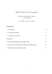
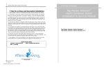
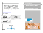
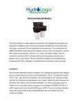
Tap Master Series Reverse Osmosis System—Owners Manual Perfect Water Technologies 10 Tips for an Easy and Successful Installation Tap Master™ Series 1. Keep it simple - there are 4 connections to make, and the tubing is color coded. VIDEO INSTRUCTIONS ARE AVAILABLE ONLINE (6 PARTS) 2. Have plenty of time, light, space, and towels before getting started. If everything goes well, you should be done in 45 minutes. However, if your feed water line is a different size, or if you don’t have an extra hole for the faucet, it can take somewhat longer. 3. NEVER use plumber’s putty, thread-lock, or anything else you wouldn’t eat on any part of this system. You may use as much white Teflon plumber’s tape as you like. If you use plumber’s putty on your faucet, you will have disgusting and potentially toxic water for the life of the faucet. Reverse Osmosis System Installation & Service Manual 4. Mount the faucet first, and when making the final connection, use the quick connect faucet adapter found in the bag of parts with the EZ adapter, tank valve, and drain clamp. 5. If you have a 3-hole sink and want to avoid drilling a 4th hole for the RO faucet, then get a single handle kitchen faucet. This will free up 2 holes, one of which you may use for the RO faucet, the other you can use for a soap dispenser or side sprayer. 6. Mount the Tap Master vertically so that the blue cap is on top. There is only one “blue cap” and it has only fitting at its top. Mount the (optional) permeate pump correctly nothing will work. There is a big arrow on the permeate pump, make sure it points up. 7. Mount the drain saddle on a vertical section of drain pipe. IF you have to mount the drain saddle on a horizontal section, then drill the hole on the top side of the pipe or at least at an angle where the drain water from the Tap Master drops down into the drain pipe. [Think of a manhole passage into the sewer] When making the connection from the system to the drain saddle wrap the tubing around the drain pipe a few times, so that some loops of tubing are higher than the fitting. Tap Master Tap Master Artesian Full Contact Tap Master IRON Tap Master UV Tap Master ULTRA 8. DO NOT touch the air nipple on the side of the reserve tank. You may be tempted to check the pressure, or pump it up – don’t. It already has plenty of air. Adding more will not boost flow, it will only decrease tank capacity. 9. Read the instructions thoroughly before beginning. There is allot of information there, some of which you may not need for your application. If you have questions – call or email. Email will usually be answered within hours even at night. 10. Have patience. Your new Tap Master may take some time to break in and start flowing. Make sure you fill, and drain, the reserve tank at least twice. TUBING COLOR CODING ORANGE—LINE IN BLACK—TO STORAGE TANK RED— TO DRAIN BLUE—TO RO FAUCET Perfect Water Technologies, Inc. Copyright © 2013 Page 12 Customer Service Hotline 1-877-693-PURE Customer Service Hotline 1-877-693-PURE Tap Master Series Reverse Osmosis System—Owners Manual Page 2 Customer Service Hotline 1-877-693-PURE Page 11 Customer Service Hotline 1-877-693-PURE Tap Master Series Reverse Osmosis System—Owners Manual Tap Master Series Reverse Osmosis System—Owners Manual (There is only one fitting on the top of the membrane housing, the bottom has two - one Tap Master Contents: white, one grey). Point the tube you have just disconnected into a pitcher and turn on the EZ adapter valve. The water flow from the tube should be fairly strong. 1 1 2. If the flow to the membrane housing is strong, then check the water flow exiting the white fitting at the bottom of the membrane housing. The water flow from the tube should be a thin, but steady trickle. If not, then the membrane is plugged and should be 1 replaced. Please note that the minimum water pressure for the system to operate is 40psi 1 3. If the flow to the membrane housing is weak, then start working your way backward and check each connection point until you find the blockage point. At each point - turn off the 1 water at the EZ adapter and tank, and briefly turn on the RO faucet at the sink to relieve 1 any system pressure. Disconnect the tube from the fitting. Point the tube you have just disconnected into a pitcher and turn on the EZ adapter valve. A 1 4. lso remember to inspect your drain line where the red tube connects to the drain saddle, 1 and you can also unscrew the grey elbow at the bottom of the membrane housing. If gunk is obstruction the drain line, then the system cannot produce good water. 1 Discoloration of water The first batch of water produced from your purification 1 1 1 system may be discolored due to the presence of carbon from the carbon filters, and a small amount of preservative. This is normal. DO NOT drink the first 6.5 gallons of water. Drinking from un-flushed system may cause gastrointestinal discomfort, 1 colic and/or diarrhea. Consult a physician if discomfort persists. Running out the first two tanks will effectively flush out the system, and make it ready for use. The tank is full when the hissing or clicking stops. Instruction book: detailed descriptions, photos and troubleshooting guide. 10” Sediment pre-filter: 5 micron bonded spun poly with high holding depth, 1year service life. 10” IRON pre filter1: 5 micron granular activated catalytic carbon with KDF85, 12month or 3000 gallon service life. 10” Carbon pre filter2: 5 micron granular activated carbon (coconut shell carbon), 1-year or 3300 gallon service life. 10” Carbon post filter: 5 micron granular activated carbon (coconut shell carbon), 1-year or 3300 gallon service life. 10” Artesian post filter4: 5 micron granular activated carbon (coconut shell carbon) with advanced remineralization media, 1-year or 2500 gallon service life. Thin Film Composite membrane 0.001 micron ultra-fine pore, 50 gallon per day, 3 -5 year service life. UV filter3 1-year service life, with electronic transformer (110v) featuring replaceable UV bulb. Flow restriction architecture: integrated flow restrictor and water check valve, central auto shut-off valve. Drain saddle; all fittings and connecting hardware. Reserve tank: 3.2-gallon (or 9 gal upgrade) , stand, quick connect ball valve Chrome long reach sink faucet (or custom faucet); quick connect fitting and hardware. EZ adapter—feed water adapter 3/8” mc x 3/8” fc x 1/4” tube Maintenance Schedule Sediment filter annual replacement Carbon filter(s) annual replacement IRON filter Permeate pump should be mounted with inlet and outlet ports to the sides, and the center indicating arrow pointing up. 1 annual replacement (ULTRA & IRON ONLY) UV bulb3 annual replacement Membrane (50 gpd TFC) 3-5 year replacement Artesian filter annual replacement General System Specifications Feed water: PSI 40 - 100 PSI Feed water Temperature: 40˚ - 100˚(F) Max. Total Dissolved Solids (TDS): 2000 ppm Max. Hardness: 10 gpg pH limits: 4 - 10 1 Included with Tap Master IRON and ULTRA only. 2 Included with Tap Master standard and UV only. 3 Included with Tap Master UV and ULTRA only. Page 10 Customer Service Hotline 1-877-693-PURE 4 Included with Tap Master Artesian only. Page 3 Customer Service Hotline 1-877-693-PURE Tap Master Series Reverse Osmosis System—Owners Manual Tap Master Series Reverse Osmosis System—Owners Manual System Location The Tap Master may be installed under a sink, or in a basement within 20’ feet of the RO sink faucet as long as the Tap Master is not subjected to freezing temperatures. The Tap Master No water or ice from refrigerator water center Make sure line from Tap Master RO to refrigerator has pressure. Make sure refrigerator water center and/or icemaker are turned ON, should be mounted vertically where the drain line out is at the bottom. Mount the reserve tank on and refrigerator is plugged in. If water center works, but icemaker does not, then defrost the a sturdy shelf, because it will weigh over thirty pounds when full. freezer as the line may have frozen. Tools Required Safety glasses Towels Phillips screwdriver Scissors Medium Crescent wrench Medium pliers Felt tip pen or marker Unscented bleach Variable speed corded power drill (3/8” for the sink hole, ¼” for the remainder) ¼” metal drill bit w/ cobalt tip ½” metal drill bit w/ cobalt tip (not required if sink has a pre-drilled hole) ½” masonry drill bit (not required if sink has a pre-drilled hole, or if sink is not porcelain) Hissing or flowing sounds from Tap Master RO are normal during the water purification process. VIDEO INSTALLATION INSTRUCTIONS AVAILABLE ONLINE www.theperfectwater.com/Installation-Instructions.html Sounds should last for approximately 1 hour per gallon of water used. Sounds should stop once the reserve tank is full. Permeate pump equipped systems will “click” and “whoosh.” A GROANING sound upon start-up indicates air bubbles in the automatic shut off valve. This will go away with time or your can pull the Tap Master off of its mounting clips and rotate it 90° left and right while the system is operating in order to pass the air bubbles. Repeat as needed. Air Bubbles/Grey Tinted Water: tiny air bubbles often accompany a new system installation and filter changes. Air becomes trapped inside the tiny carbon pores and is released over time, not gallons. After pouring a glass of water, allow a few seconds for the water to clear. Enjoy! Drilling hole for RO faucet – porcelain sinks steps 1-5; stainless sinks steps 3-5 WARNING: Serious cracking and damage may occur to your sink even if instructions are followed Weak pressure at RO sink faucet & Reserve tank filling slowly exactly due to age and the imperfections inherent in natural materials. Instructions may not NOTE: Seasonal changes in temperature can cause pressure imbalances within the system apply exactly to your sink. Use caution – sink may be slippery. resulting in slow water production. Oftentimes the imbalance will correct itself on its own within a few days. You may also restore the internal system pressure balance by draining the tank, TUBING COLOR CODING ORANGE—LINE IN BLACK—TO STORAGE TANK RED—TO DRAIN BLUE—TO RO FAUCET unplugging the tubing from the tank, then allow the system to stand open overnight. Turn it back on, and allow the tank to refill. Weak pressure is either a storage problem or a production problem. To determine which close the tank valve and open the RO faucet. You should see a constant trickle of water. If this is what you see then it’s a storage tank problem. If you see zero water, dribbles out, or a few 1. Remove base cover plate from RO faucet packaging. Line-up base cover plate with other sink faucets. See Fig 1. Check underside of sink for spacing from trim, curvatures, and other obstacles. See Fig. 15. Don’t place spigot too close to obstacles - leave yourself enough room under the sink to use hand tools. Either right or left side of the sink is OK provided previous conditions are met. Mark center of base cover plate with marker. See Fig 2. Place towel underneath sink, below drilling site, to collect fillings. Always wear protective eyewear and gear while drilling, and while under sink. 2. Using ½” masonry bit and variable speed corded power drill, slowly begin drilling through the porcelain. Drill bit should be perpendicular to sink. Failure to do so may cause the drill bit to slip and cause bodily injury, and/or property damage. Rinse & dry drill bit tip and sink area with cool water for every 20 seconds of drilling to prevent drill bit overheating and sink damage. Small localized flaking or chipping may occur. Use caution – drill bit may be very hot. DO NOT touch drill bit. Electrical hazard! DO NOT allow power drill electrical components to come into contact with water. Use caution – sink may be slippery. 3. When metal is struck, switch to ¼” metal bit with cobalt tip. Drill bit should be perpendicular to sink. Failure to do so may cause the drill bit to slip and cause bodily injury, and/or property damage. Begin drilling to drill a hole all the way through the sink. Rinse & dry drill bit tip and drops only then it’s a production problem. Storage tank problems: 1. Make sure storage tank is full, and has been flushed at least twice (6.5 gallons). 2. Make sure the angle-stop is wide open. 3. Check all tubing for kinks or sharp bends - this can impede the flow of water. 4. Check reserve tank air pressure with tank empty, system off and faucet open. Air valve is located on the side of the tank under a cap Use a bicycle tire pressure gauge. Tank should have 7.5 psi. If the pressure is less, then add air using a bicycle pump. Do not overfill. If the tank does not hold the air then the tank is bad and should be replaced Production problems: 1. Check flow to the membrane housing. Turn off the water at the EZ adapter and tank, and briefly turn on the RO faucet at the sink to relieve any system pressure. Then pull the black tube out of the top of the blue membrane housing at the quick connect fitting. Page 4 Customer Service Hotline 1-877-693-PURE Page 9 Customer Service Hotline 1-877-693-PURE Tap Master Series Reverse Osmosis System—Owners Manual Tap Master Series Reverse Osmosis System—Owners Manual sink area with cool water for every 20 seconds of drilling to prevent drill bit overheating and USING QUICK CONNECT FITTINGS sink damage. Small localized flaking or chipping may occur. 4. When ¼” hole is completely drilled through, switch to ½” metal drill bit w/ cobalt tip. Drill bit should be perpendicular to sink. Failure to do so may cause the drill bit to slip and cause bodily injury, and/or property damage. Begin drilling to enlarge the ¼” hole to ½” all the way through the sink. Use caution when hole is near completion to avoid damaging sink surface. Rinse & dry drill bit tip and sink area with cool water for every 20 seconds of drilling to prevent drill bit overheating and sink damage. Small localized flaking or chipping may occur. 5. When ½” hole is drilled through completely, install RO faucet with provided mounting hardware. For more details, see mounting instructions enclosed with hardware. See Fig. 3. Connect Tap Master to RO faucet using Quick connect faucet adapter as outlined later. Installing The Tap Master Reverse Osmosis System A. RO Faucet—Mount faucet according to the installation instructions enclosed with faucet packaging. Remember to use the 3/8” push-in x 7/16UMS threaded faucet adapter included in the parts bag rather than the 1/4” brass nut included with the faucet. Troubleshooting 1. Install EZ adapter on cold water line - Always wear protective eyewear while under sink. Locate the cold angle-stop (the main water lines under the sink – one hot water, one cold IMPORTANT NOTE: Before performing service on the Tap Master RO at any time, and for water), and turn clock-wise to shut off the water. See Fig. 4. Locate 3/8” fitting, typically any reason: first close all under-sink water valves, except for the RO faucet which you found on the line out of the angle-stop (see Fig.7) or where the existing line connects to the should open to relieve system pressure and drain away excess water from the lines. Push- kitchen faucet. See fig. 6. Disconnect the 3/8” fitting on either the angle-stop or the kitchen pull and quick connect fittings are nearly impossible to remove when under pressure. faucet. Use Teflon tape on the EZ adapter and the angle-stop male threads, and make sure o- Leaks from metal fittings Unscrew fittings and re-tape male fitting. Tape should be wound 5 -7 times around male thread. Tape should not cover opening. Use only Teflon tape. Retighten fitting securely. Over tightening can crush the tubing insert and cause a water blockage. rings are properly seated. Fit the EZ adapter and tighten. Check for water pressure & leaks on ball valve. Turn ON water by rotating angle-stop counter-clockwise. Close ball valve, by turning the handle perpendicular to the ball valve body. (Valve is closed in Fig. 7) Have a bowl or cup nearby to catch water. Dry all parts, check for leaks, and snugness. VIDEO INSTALLATION INSTRUCTIONS AVAILABLE ONLINE Leaks from plastic fittings Plastic fittings should be firmly finger tightened. Under tightening can result in leaks, over tightening can crush the tubing and result in a water blockage. 2. Install drain saddle clamp and drain line – Identify a vertical section of drainpipe with For plastic fittings only; make sure the plastic tubing has an insert in the tube end, and a enough space to mount the drain saddle clamp. See Fig. 8 & Fig. 10. Drain pipe material can feral (o-ring which compresses the tubing around the insert) in the plastic female fitting. be either metal or plastic. Locate drain hole template supplied with drain saddle clamp, and Drain tubing does not need an insert. peel off its backing. Place the template on the previously identified location of drainpipe for the drain saddle clamp. Place ¼” drill bit inside template hole, and drill a hole into the drainpipe. Leaks from push-pull or quick connect fittings Disconnect fitting by depressing the collet Drill through one side only. DO NOT drill a hole clean through both sides of the drainpipe. This ring on the fitting with one hand and pulling out the tubing with the other hand while the will result in a leak, and require replacement of that piece of drainpipe. Mount the drain saddle collet ring is still depressed. Tubing cannot be pulled out without depressing the collet ring, clamp on top of the template with the holes aligned. You may use a screwdriver to align the and relieving system pressure. Make sure the tubing is cut is straight, the edge is holes. Fit drain saddle clamp back-plate and screws. Alternate tightening screws on each side completely smooth, and the tube is rounded. Scratched, gouged, damaged, or oblong of the drain saddle clamp to ensure an even, snug fit. See Fig. 10. Locate RED 1/4’ drain tubing end will leak. Re-insert the tubing into the push-pull fitting. Push tubing all the way tubing and push on black plastic nut found in drain saddle bag. Hand tighten black plastic nut in, then pull back gently, to check fit. Most push-pull fittings take about a 1/3” of tubing onto the drain saddle male fitting until it is snug. Wrap excess tubing around the drainpipe. inserted into them. 2a. Mounting Permeate Pump (optional) - Mount permeate pump side by side with the tap master using supplied mounting clip and screws. IMPORTANT: permeate pump must be Page 8 Customer Service Hotline 1-877-693-PURE Page 5 Customer Service Hotline 1-877-693-PURE Tap Master Series Reverse Osmosis System—Owners Manual Tap Master Series Reverse Osmosis System—Owners Manual mounted with indicator arrow pointing up. Indicator arrow is the large, center of the reserve tank. Using eyedropper or a small spoon, place a few drops of unscented bleach arrow. See page 10 for mounting orientation diagram. inside the 1/4” threaded water stud at the top of the storage tank. Wait 2 minutes then shake out into sink.. DO NOT touch the air nipple near the bottom of the tank found under a blue 3. Install refrigerator kit (optional) – Installation may vary according to make, model, cap. Apply white plumbers pipe tape to 1/4” water stud on top of the reserve tank. Fit the and age of your refrigerator. Make sure refrigerator icemaker and water center are turned reserve tank shut off valve (see picture below) to the 1/4” water stud. Hand tighten until it is OFF. Clean area below and around refrigerator thoroughly. Use care when rolling out snug. Over tightening may cause damage. See Fig. 11. Insert BLACK 3/8” tubing into the tank refrigerator. Flooring may become scratched, gouged or damaged from moving refrigerator. shut off valve. Push tubing all the way in, then pull back gently, to check fit. Most push-pull Consult your local licensed contractor or plumber for trimmed-in refrigerators, or refrigerators fittings take about a ½” of tubing inserted into them. Make sure reserve tank shut off valve is without rollers. Roll out refrigerator. Unplug refrigerator electric plug. Locate water line in for in the CLOSED position, where the blue handle is perpendicular to the body. refrigerator. (Yours may already be connected to a water line from wall. If so use local anglestop to shut off water. Disconnect female fitting. See Fig. 13.) Plan the route for the water line from the Tap Master. Drill ¼” holes through the lower cabinetry, high along the back wall just below the drawers. See Fig. 9. Make sure cabinet contents are removed, prior to drilling, and ¼” tubing does not come into contact with drawers, doors, or sharp objects. Smooth the holes free from splinters and sharp edges. [Alternate route for refrigerator line -- run ¼” refrigerator tubing along the baseboard, and enter the kitchen sink cabinet by drilling a ¼” opening in the bottom board of your kitchen sink cabinet, towards the front baseboard.] Push tubing through the cabinetry holes from the Tap Master to refrigerator. Allow 2-4’ of extra tubing at the refrigerator, and position it so that it cannot be crushed or otherwise damaged while rolling the refrigerator. Connect the female metal fitting from the refrigerator kit to the male metal fitting on the refrigerator. See Fig. 14. Make sure all male metal fittings are thoroughly Teflon taped to prevent leaks. Do not roll back refrigerator until the Tap Master is fully installed and operational. Make sure shut off valve on the refrigerator connection kit at the Tap Master is in the CLOSED position, where the blue handle will be perpendicular to the —> VIDEO INSTALLATION INSTRUCTIONS AVAILABLE ONLINE <— 7. Pressurize the Tap Master RO - For Tap Master UV & ULTRA first connect power adapter to UV filter so the filter glows. If unit fails to illuminate, then check power outlet with a known good device. Many undersink outlets are switched. Make sure unit is dry. Water should flow normally from your main kitchen faucet. Double check to make sure all valves are in the closed position, except for the main angle-stop valve, which should be open. SLOWLY open the EZ adapter ball valve. You should hear water rushing through the system. Open the RO faucet to by flipping the lever up, where it should stay open. A trickle of water should be present after 2-20 minutes. Some blackening of the water may present due to loose carbon being flushed out. Close the lever on the RO faucet after the trickle runs clear, and allow the system to pressurize. When the system has pressurized and shut off - check for leaks. The open the reserve tank valve slowly. Allow reserve tank to fill for 2.5 hours, and then drain completely. You will drain the tank by first closing the EZ adapter body. ball valve then opening the RO faucet again. Let run until water stops completely. Close Ro 4. Mount the Tap Master - Identify location for installing mounting clips for the Tap Master least twice prior to use. [OPTIONAL-Plug in refrigerator electric plug; open refrigerator line ball faucet. Open the EZ adapter ball valve and let refill and repeat. System must be flushed at RO unit. Location should allow room for the reserve tank, for connecting and disconnecting the unit, and enough room for performing general service on the unit. Typical locations are on either right or left side, near the back wall. Use supplied mounting clips and mounting template located inside back cover. Tap Master should be mounted vertically where the drain line out is on the bottom of the Tap Master. See Fig 8 & 12. Insert ORANGE 1/4” tubing into EZ adapter used in step 1. valve so that the blue handle is parallel with the white body. Make sure refrigerator icemaker and water center are turned ON. Check for leaks. Check for pressure at the refrigerator’s water center. Dispose of the first two batches of ice after installation. Use caution when rolling refrigerator back into place. DO NOT crimp or crush water line, as a leak will likely develop.] IMPORTANT – After reserve tank has filled (2.5 hours), Drain entire reserve tank completely, until the flow from the RO faucet falls to a thin steady trickle. Repeat. Reserve tank is full when the hissing or clicking noise stops. Discoloration of water may be present. System must be flushed twice prior to use. Allow another 3 hours VIDEO INSTALLATION INSTRUCTIONS AVAILABLE ONLINE for the reserve tank to refill. 5. Install water out line to RO faucet – Apply plumbers tape to threaded shank. Screw quick connect faucet adapter onto the bottom of the RO faucet threaded shank until it is snug. See Fig. 15. Over tightening may cause damage. Do not use 1/4” brass nut which may be present. Insert BLUE 3/8” tubing into quick connect faucet adapter. Push tubing all the way in, then pull back gently to check fit. Most push-pull fittings take about a ¼” of tubing inserted into them. 6. Install reserve tank and connect reserve tank tubing – Affix product label to the top Faucet Adapter Page 6 Customer Service Hotline 1-877-693-PURE EZ Adapter Tank Shut-off Valve Page 7 Customer Service Hotline 1-877-693-PURE