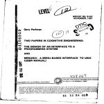
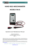
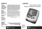
1
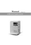
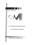
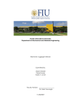
NRTC Model Train Controller
Operator and Reference Manual
A- and B-Models
June 2008, revised June 2013
Contents
1 Introduction
2
2 Using the Controller
2
3 Automation of Layouts
9
Appendices
11
A How Speed-Regulating Controllers Work
11
B Wiring Up the Controller for Station and Siding Stops
14
C Technical and Service Information
17
1
1
Introduction
The NRTC series of model railway controllers are a revolutionary new design that offers
the speed-control of “feedback” controllers without pulsed power or any of its inherent
problems such as motor overheating.
Features of the NRTC include:
• Precise speed control by feedback regulation of engine RPM;
• The gentle action of traditional, fully-analog drive voltage, not PWM, to guarantee
that delicate locomotives are not overheated;
• Shunt (center-off) and Cruise (anticlockwise-off) modes to suit layout and operator
needs;
• Adjustable simulated inertia (momentum), and an override switch to disable inertia
for setting up;
• Momentary-action braking when using simulated inertia, for realistic driving;
• Interlock against reversing at speed;
• Timeout mode (“dead man switch”) to halt unattended trains;
• Full overload protection;
• Station stopping with “ABS” constant-distance pull-up (A model only);
• Automatic station stops with and without reversing, for automation of layouts (A
model only);
• Different acceleration and coasting deceleration rates when using simulated inertia
(A model only).
2
Using the Controller
The front panel of the NRTC is pictured in figure 1. The controller has a throttle
knob, a throttle lever, a direction switch, and a switch to turn inertia (called
momentum on US models) on and off. It has a Multifunction indicator and an
Actual Direction indicator. The throttle/brake lever appears only on the A
model.
A major differentiating characteristic of the NRTC controllers is the ability to work in
“shunt” mode, where the knob is a center-off control that is turned one way to make the
train go backwards and the other way for forwards, as well as “cruise” mode, where the
throttle knob sets speed and the reversing switch sets direction. If the knob is near the
center position when the power is applied the controller works in the center-off, “shunt”
2
Figure 1: Front panel layout of the NRTC, A-model shown. The Throttle/Brake selector
is absent from the compact, B-model.
mode. If the knob is closer to the full-anticlockwise position when the power is applied the
controller works in the “cruise” mode, with full-anticlockwise being minimum throttle.
This startup decision works quite well, since the control is most usually left in the “off”
position, and this is near full anticlockwise if the control is “zero-off” mode, and it is
uaually turned through half the travel if it has been in “center-off” mode.
The left-right “shunt” mode is indicated by the Multifunction indicator blinking short
double flashes and the left-off “cruise” mode is indicated by single flashes. These flashes
of the Multifunction indicator are called a “heartbeat” signal. They consist of a onesixteenth second green flash every second in Cruise mode, and two one-sixteenth second
flashes close together every second in Shunt mode.1 In Shunt mode, the full-speed available
1
Think of the two flashes as suggesting that the knob can be turned to either the left or the right.
This mnemonic helps you remember the meaning of the heartbeat.
3
from the controller is somewhat lower than that available in Cruise mode. This makes
for smoother action of the control knob, and is convenient as high speed is not usually
required when shunting.
In normal running, the train is started by switching the throttle switch to the accelerate position and turning up the throttle knob. The train is stopped by paddling
the throttle switch to the brake position. The brake position is sprung, so that when
the switch is released the brakes are released, and the train coasts. The train can be
driven simply by moving the switch between the accelerate, coast and brake positions as
required, leaving the throttle knob at a suitable thrust level.
The train can also be controlled by leaving the throttle switch in the Drive position,
and adjusting the throttle knob. In this situation, the NRTC-A acts like an NRTC-B,
which has no throttle switch on its panel. This is the more conventional arrangement
for train controllers.
Dead-man Function
The controller has a “dead-man” function. If no adjustments are made to the speed for a
period of about half an hour, the controller goes into its “standby” or “dead-man” mode.
This is signalled by a slow, even (1 half-second flash per second) yellow flashing of the
Multifunction indicator. The train is stopped when in this mode. Touching either
the brake or the speed knob will reset the controller into its “active” mode and allow the
locomotive to be driven.
The controller starts in the standby mode as a safety precaution, so that locomotives do
not take off as soon as power is applied if the control knob has been left turned up.
Inertia/Momentum
The controller is provided with an inertia switch that allows you to turn the simulated
inertia off and on. On some models, inertia is called momentum instead. When inertia
is on, the brake switch causes the train to slow down more quickly, just as pressing the
brake pedal in a car slows it down more quickly than simply removing your foot from
the accelerator. Driving the train into a station and stopping at just the right position
requires some skill. Upon approach to a stop the throttle switch is pulled to the center
position, and the train begins to coast. The brake lever is paddled on and off to slow the
train at the correct rate to finish aligned in a station.
The simulated inertia makes for more realistic operation. However, it can be annoying if
you only want to set things up on the layout, so it can be bypassed by switching inertia
off. With inertia off, the train immediately obeys the controls, rising as quickly as
possible to the speed set by the knob, and stopping immediately if the throttle switch
is moved out of the accelerate position, and reversing immediately if the reverse switch is
toggled.
With inertia switched on, sudden reversal of the direction does not cause the model
4
to suddenly change direction. Instead the train slows to a halt and then immediately
takes off in the reverse direction. The Actual Reverse indicator shows the change of
direction only when it actually happens. With inertia switched off, the reverse switch
is ignored until the train is halted. Thus the locomotive is never instantly reversed.
Reversing
In Cruise mode the direction switch selects forward or reverse direction. In Shunt mode,
the direction switch changes the sense of the knob: If you want a clockwise twist to
make the train go forward but the track is wired so that it goes backwards, change the
position of the direction switch and the sense will be inverted. The direction LED
indicates the actual polarity delivered to the track. It is useful for indicating exactly when
the train reverses direction, since inertia can delay a reversal of direction for some time
after the user reverses the thrust, and without inertia the reverse request can be ignored
until the train is manually slowed.
Multifunction Indicator
The indicator above the throttle knob provides information about the train and controller.
This is the list of indications and their meanings.
Cruise Heartbeat This is a single short blink every second. This is the normal healthy
indication in Cruise mode. Knob operates anticlockwise-off, and the train is put
into and out of reverse by means of the direction switch alone.
Shunt Heartbeat This is two short blinks every second, a “blip-blip-pause” sequence.
This is the normal healthy indication in Shunt mode. Knob operates center-off. The
direction switch reverses the sense of the throttle knob.
Boot Indication When first turned on, the light flashes yellow very quickly, about 15
times per second for around 2 seconds. This tells you that the controller has passed
self-test. If this sequence occurs, you know that the power has just been applied.
Time Out This is the “dead-man” indication, and consists of slow even yellow flashes,
half-second on, half-second off. Adjusting the throttle knob by more than 5
degrees or pressing the brake lever cancels this mode.
Open Circuit This is a sequence of four short red flashes repeating every second. It
occurs if the locomotive is off the track or a connection is broken between the
controller and the track.
Overload A long red flash with a short dark blink every second indicates an overload or
short circuit. It means that the controller was asked to deliver too much current.
This may happen when there is a derailment and metal lies across the rails, or if you
have too many locomotives on the track. This is a latching condition that switches
off the power to the rails to protect train and controller, and is reset by pressing the
brake lever or cycling the power.
5
Stationing This is a continuous series of short blinks in green. It shows while the train
has been halted by the autostop function. Operation will resume after the preset
interval.
2-dash This is two long blinks (one-quarter seconds long each) every second, separated
by one-quarter second, a sort of “dash-dash-pause” sequence. It means the controller
is in set-up mode. If yellow, the knob may be turned to set the inertia. If green,
the knob may be turned to set stopping distance. If red, the knob may be turned
to set the timeout (dead-man) interval. When the button is next pressed the set
will advance to the next step. If the knob is not adjusted by at least 5 degrees, no
change occurs.
3-dash This is three long blinks (one-quarter seconds long each) every second, separated
by one-quarter second gaps, “dash-dash-dash-pause”. If yellow, the knob may be
turned to set the braking strength. If green, the knob may be turned to set the
station-stop interval.
Controller Presets
The NRTC has a number of preset values. These include the amount of inertia, the
strength of the brakes, the period of time associated with the dead-man switch, the
station-stop distance, and the station-stop interval. These are preset to levels that we
believe most modellers will find confortable. However, they can be changed to suit your
taste or the dimensions of your layout.
If the brake switch is held down for 3 seconds with inertia off, a setting function is
activated, rather like setting the time on a digital wristwatch. This allows the user to
adjust the preset parameters of the controller. The controller then allows each of the things
listed above to be set via the knob, in turn. Momentarily pressing the brake advances
from one item to another, until the last press saves the new values to non-volatile memory
and returns the controller to normal operation2 . While setting, the previously-selected
speed setting remains in force, so that you may have a train running, and observe the
effects of changes in the background.
The inertia switch can be switched back to restore inertia once setting has started, it is
not required to be off throughout the setting procedure.
Here is a description of the various things that can be changed:
1. The station-stop interval sets the period of time that a train remains stationary
after an autostop. The knob sets the interval from 8 seconds to about three and a
half minutes.
2. The no-retrigger interval sets the period of time before which a train can trigger
another autostop. This interval can be important if a train halts while it is still on
2
The save to permanent memory only occurs on the last button press of the sequence. Thus, if you
feel that you have messed up the setting sequence, removing power before you finish cancels the changes.
6
the detector, as it gives a time for the train to clear the sensor. The knob sets the
interval from 3 to 60 seconds.
3. The “dead-man” timeout duration is the period of inactivity before the controller
goes to “stand by” and automatically stops the train. If the controls are not touched
for a time, the controller assumes the train has been forgotten, and automatically
halts its motion. This is the delay on the so-called “dead-man switch”. It can be
set from 1 minute to 200 minutes (over 3 hours).
4. The inertia constant sets how long it takes the locomotive to come up to speed and
to slow down when coasting to a halt. The knob roughly varies so as to cause a
train to take anywhere from 0.1 seconds to 30 seconds to coast to a standstill.
5. The braking constant sets how rapidly the train comes to a halt when the brake
button is manually depressed. The value controls how much faster the brake is able
to slow down a train compared to allowing it to coast to a standstill; with the knob
set all the way up to maximum, the brake will stop the train in half the time it would
take to coast to a stop. With the knob set to a low value (mostly anticlockwise) the
brake will stop the train very quickly indeed, as if the brakes apply to all wheels at
once. When the knob is turned to the 9-O’clock or 10-O’clock position the effect is
most realistic.
6. The stopping distance sets the length of track the train will travel after the autostop
signal occurs (typically the distance to the station from the position of the local block
detector). The autostop or stationing function operates something like the ABS in
a car, computing an optimum amount of braking effort to exactly position a train
in a station or siding, irrespective of how fast it was travelling when the braking
started. Section 3 describes the use and setting of this function in detail.
Suppose you wish to change the station-stop distance from its default value, so that your
trains stop neatly at your platforms. The sequence goes like this: Switch off inertia; hold
the brake on for three heartbeats; release the brake, observe double yellow dashes on the
Multifunction indicator, showing that the controller is ready to set the first preset
(inertia); press the brake lever two more times, and observe double green dashes; adjust
the knob and leave it at about the 9 O’Clock position, to give a “short” distance; press
the brake at least three more times. Now you can test the new value. This procedure
becomes easy to remember once practiced a couple of times.
In general, a full setting sequence might go like this: Switch off inertia; hold the brake
on for three or four heartbeats; release the brake, observe double yellow dashes; restore
the inertia switch to the on position. You are now ready to adjust presets. The double
yellow blinks show that the controller is ready to change the inertia. The maximum value
corresponds to the control turned up to full speed, fully clockwise, the minimum or zero
to the full counter-clockwise position. Using the clockface analogy 7 O’clock is the zero
position and 5 O’clock the full-up position.
If you do not wish to change the value, leave the control untouched. The value will not
be altered no matter the position of the knob if you make no adjustment while at this
stage. If you want to change the inertia, adjust the knob.
7
When satisfied with the inertia setting, press the brake lever again. The controller will
advance to setting the braking strength. The signal becomes three yellow dashes of
187ms duration, spaced 65ms, every second, a dash-dash-dash-pause pattern. A small
value means that the brake button will have very great effect. A larger value means that
the brakes will seem to work very weakly. Too small a value makes the train stop quite
quickly—unrealistically so, if desired.3 Again adjust the control if you wish to change
braking, make no adjustment to leave it unaltered. When satisfied with the value, press
the brake lever again.
The controller will advance to setting the station-stop distance. The signal becomes two
green dashes of 187ms duration, spaced 65ms, every second. Again adjust the control if
you wish to change the value, make no adjustment to leave it unaltered.
When satisfied with the station-stop distance, press the brake level again. This time the
controller will set the station-stop interval. The signal becomes three green dashes of
187ms duration, spaced 65ms, every second. When satisfied with the value, press the
brake lever again.
Finally the controller displays the code for the last preset, two red flashes. This corresponds to the duration before the “dead man” circuit shuts off the train. A counter
counts minutes; it is reset every time the knob or brake is touched. If it counts the preset
number of minutes, the train is slowed to a halt until the knob or brake are touched, at
which point it resumes where it was left off. The control can set from 1 to 200 minutes (a
little less than 3 and one-half hours) delay. The factory default is about 30 minutes, or
half an hour. If you have children who may use the layout, a short time of 5 minutes can
preserve locomotive life. If you are a shopkeeper with a display layout, a couple of hours
allows for long display followed by controlled shutoff after you leave.
Press the brake again. This time the controller returns to normal operation, the signal to
the heartbeat, and the changed values are written to non-volatile memory.
This table is a quick reference for setting. To enter set mode, switch inertia off, and press
the brake for three flashes of the heartbeat signal. Values will not change if the knob is
not adjusted.
Color
Flash pattern
What is being set
Defaults
GREEN
dash-dash
station halt time (6–200 s) (time at station) 12 s
GREEN
dash-dash-dash no-retrigger time (3–60 s) (time to clear)
8s
YELLOW dash-dash
deadman timeout delay (1min–2hrs)
30 mins
RED
dash
inertia coefficient (weight of train, 1–200)
50
RED
dash-dash
braking strength constant (1–200)
50
RED
dash-dash-dash stopping (ABS) distance (about 1–200cm)
30
3
Bear in mind that the braking interacts with the inertia; if you have virtually no inertia, there will
be little point in braking at all, so this setting becomes unimportant, since the train will stop almost at
once when the speed knob is turned down anyway. The braking always acts more forcefully than the
acceleration. The value set here controls how much more forcefully.
8
Factory Reset of Preset Values
The factory reset state is invoked by applying power with the control knob turned fully
up. If this is the case at the end of the initial, 2-second startup period, the predetermined,
factory-default set of coefficient values are used to overwrite the working set.
This function is useful if you have been adjusting the coefficients to see their effects, and
you want to return to a known, modest feel of operation, or if you intend to use the
controller alternately with layouts of different scales.
3
Automation of Layouts
The conroller can accept an “autostop” signal. This is typically a logic signal from a block
detector on the approach to a station. The purpose is to enable automatic stopping at
a station, or stopping with reversal at a terminus or siding. The signal is applied via a
3.5mm connector on the rear of the controller.
When the signal is received, the controller shows a fast-flashing indication on the indicator
LED, and the train is decelerated to a halt for a number of seconds. This stationing
duration is set and stored in the controller’s non-volatile memory. The controller attempts
to apply brakes to the correct extent to bring the train to a stop the same distance from
the block detector irrespective of the speed when the block is entered. This distance is
also set and stored in the controller’s non-volatile memory.
Of course, there are limits to the ability of the autostop mechanism. If the train’s speed
is so low and the stopping distance Ks so large that the train coasts to a halt too soon
without any braking (easily the case if there is very little inertia set by Kj ), the autostop
will miss. It will miss if the train is travelling very fast and the distance is set to a small
value. However, within physical limits, the autostop is a good autopilot.
The signal required is a connection from the autostop input to ground. The autostop
cannot be retriggered for a few seconds after the train restarts. This is to prevent the
rear of a long consist from retriggering the block detector if the stop distance is less than
the length of the train, or in the case of a train reversing out of a siding and triggering a
second stop as it must again pass the block sensor.
If the autostop function is to be disabled, the connection to the autostop input must be
broken by a switch. In other words, the controller always responds to an autostop request.
The diagram below shows an example of a layout that demonstrates the use of block
detectors with the controller. To automate this layout, four block detectors could be
placed as indicated by the triangles. The detectors at either end of the passing loop
would be wired to signal a stop without reverse; the detectors near either end would be
wired to signal a stop with reverse. The directions for wiring the block detectors to the
controller are given in appendix B.
9
To initiate an automatic stop, the stationing input must be pulled towards ground. The
stationing input normally floats to +5V, through an impedance of 10kΩ. Grounding this
input, or at least pulling the line to less than 1V, triggers a station stop with reverse.
Pulling it to below 2.5 V but not less than 1 V initiates a stop without reverse. This is
best achieved with a 6800Ω resistor.
To trigger a station stop and have the train reverse, two conditions must be met. First
the controller must be in Shunt mode. Secondly, the station input must be connected
to ground directly. If the station signal line is connected to ground through a resistor of
6800 to 10kΩ, rather than directly, the train will not reverse in the stop even in shunt
mode. In the layout above, the block detectors at either end of the layout would be wired
to trigger reverse, while the center ones would trigger a simple stop without reverse.
10
Appendices
A
How Speed-Regulating Controllers Work
Model train motors are small, permanent-magnet motors with brush commutators. This
kind of engine has a very useful property: it acts equally well as a generator as a motor
(ignoring minor losses). In practice, this means that if it is being driven with a pulsed
electrical signal, in the moments between voltage being applied by the controller, the
motor is acting as a generator, and it produces a voltage. This voltage is the so-called
“back EMF” of the motor, and it is proportional to the speed of rotation of the motor
shaft.
Feedback contollers measure the speed using the back EMF, and try to adjust their
operation moment by moment to maintain constant speed in the motor. This is the basic
principle of industrial control, applied to motor speed. When operating properly, the
controller ensures that the setting you have on your control knob is the speed of the train,
not the amount of power applied, as in the case of, say, the accelerator pedal of your car.
The controller acts like a kind of cruise control.
A cruise control makes it easy to drive on the freeway. The feedback controller makes the
drivers life easier by keeping a train running at a known speed, even as it climbs hills.
However, a cruise control is not useful for low-speed work... not much call for shunting
with an automobile. Why then, is a feedback controller so popular for shunting?
The answer lies in the fact that when you scale things down and make a four-inch model
act like a 40’ locomotive, it goes wrong. There is very little weight in a model compared
to the original, no wind resistance, very different running friction and wheel slippage, yet
vastly more stiction, and very little immunity to small pieces of dirt on the track, etc.
Feedback controllers, and particularly the PWM type, help to negate the nastier of these.
Low-speed running is vastly improved in a feedback controller.
Pulse Control and Motor Heating
Many enthusiasts believe that pulse controllers overheat locomotives and are responsible
for burnouts and excessive brush and commutator wear. On the other hand, some authors
have suggested that PWM controllers do not increase the stress on motors significantly.
Who is right?
Theory aside, there is no doubt that motors run much hotter when driven by a PWM
controller. A 10 minute comparison test will show this clearly without any more accurate
measurements than the temperature sensing of your upper lip. However, such tests also
make it hard to believe that the heating could be bad enough to burn out a locomotive.
The excess heating is less pronounced at higher speeds (actually at levels closer to 100%
duty cycle of the controller, meaning with its control turned up higher). So the situation is
worse if you are using a controller designed for higher voltages than your loco requires, for
11
instance running a Z-scale locomotive with a PWM controller designed to handle G-scale
models.
Simple theory based on resistive losses says that the heat generated with pulsed drive
will be higher than the constant-dc case by a factor of the duty cycle. In other words, if
the PWM must use a 50% duty cycle to achieve the desired speed, resistive losses will be
double what they would have been with a proportional analog controller, and if it has to
use a 10% duty cycle, the losses will be 10 times greater. In practice, a small locomotive,
N-scale say, will run fast with 11 volts applied, and might shunt with 4 volts applied. If a
PWM controller applies 15 volts peak, it will run a duty cycle of between 20% and 75%,
worsening losses by anything from one third to five times. Note that the 5 times loss only
occurs when the power delivered by the locomotive is less than one-tenth of its full-power
load, so that it still represents half the power dissipation of full load. On this basis one
might feel safe to disregard the additional dissipation of a PWM controller: It can be no
worse than running at a large fraction of full speed for the same amount of time.
However, the “resistive loss” case discussd above is somewhat naı̈ve. In fact, motors are
quite complex magnetic systems. They present inductive reactance and exhibit magnetic
loss mechanisms (such as eddy-currents in the armature metal). Together with a PWM
signal, these decrease efficiency and cause heating of the motor. Worse, cooling is more
effective when the engine RPM is high, but PWM losses are greater at low speed. This
makes for the unintuitive case that burnout is more likely at low speed with PWM drive.
This is especially the case with open-frame motors that rely on convective cooling of the
armature.
Much of the energy in a pulsed signal is contained in frequencies above dc. A squarewave
signal corresponding to PWM with 50% duty cycle puts half of its energy into frequencies
above dc; this fraction increases as the duty cycle falls, as does the content at higher
harmonics of the pulse frequency. This is roughly like trying to run your dc model with
half of the energy applied as ac power instead! Above a certain frequency of operation,
perhaps as low as a few hundred Hertz, the energy is simply lost as eddy current losses
in the magnetic circuit. Efficiency would be improved if the frequency of operation, the
pulse repetition rate or PRR, was to be lowered. However, below a few tens of Hertz the
locomotive vibrates. This high-frequency loss accounts for much of the excess heating in
a locomotive driven with PWM.
It is possible to measure motor heating a small motors. Figure 2 shows temperature rise
for a small motor run at a constant speed in the two cases of plain dc and a PWM signal
with 50% duty cycle. The temperature rise is about double, as expected from the simple
theory. Figure 3 shows the temperature rise in a small locomotive motor designed to use
convective cooling assisted by an open-case frame and the armature motion. More than
double the temperature rise occurs in this case where the motor is doing one-quarter of
the work!
A rule of thumb for electric motors is that their life is halved for every 10C (18 degrees
F) rise in the armature temperature. If your locomotive feels warm to the touch on the
outside, this suggests an external temperature in the region of 38C/100F. (Luke warm
is 38C or 100F, the limit of what you can touch comfortably is in the region of 55C or
130F.) The armature temperature could be much higher, perhaps 80C/175F, especially
12
Figure 2: Case temperature rise for a small motor at 6000 RPM using DC and 50%
duty-cycle pulsed drive. The dashed trace identifies the pulsed drive. Temperature rise
corresponds exactly with the armature current form factor as predicted.
Figure 3: Case temperature rise for an N-scale locomotive motor with dc and 25% dutycycle pulsed drive of the same peak magnitude. Load was kept constant and speed alowed
to vary.
in light of the fact that locomotives do not generally have a cooling fan on the drive shaft,
as do the motors of cordless power tools, for instance. Locomotive motors tend to rely
on having an open casing and a draft created by the armature itself. This means that it
is “wearing out”—approaching burnout—32 or 64 times faster than if you had left it on
the shelf. If that sounds scary, remember that shelf life is very long, and the duty cycle of
usage is usually quite low, unless the locomotive is used somewhere like a shop window.
These lifespan considerations promoted the inclusion of the timeout or “dead man” function, and the development of Analog Waveform Drive or “AWD” in the PID684SV. These
techniques help, but do not solve the problem. The NRTC-series of controllers uses an
entirely different technique that removes the need for PWM pulse signals entirely.
13
Analog Waveform Drive (“AWD”)
Analog Waveform Drive is a method of dynamically shaping the waveform delivered to
the locomotive so as to eliminate the high-frequency losses that increase heating at low
speeds. A hardware circuit slew limits the voltage applied to the tracks, to guarantee that
no operating condition of the computer can stress the motor’s armature.
In the low-power situation where a Pulse-Width-Modulation (PWM) controller would
deliver a short, but full-amplitude pulse, the AWD circuit produces a wide triangular
waveform of lower amplitude. In this regime, the waveform is amplitude modulated. At
medium power, AWD delivers a full-amplitude waveform, but the rise times are kept
long, decreasing efficiency but keeping the wasted power in the controller, rather than
in the locomotive. At full power AWD delivers a flat-topped, full-amplitude signal with
occasional triangular zeroes to allow the motor back-EMF to be measured.
Negative Resistance Speed Control
The PWM technique of motor speed control was in usage as early as 1968. Negative
resistance speed control is a technique that was first reported in 1978. It was used on
large motors, but other techniques proved superior in that situation. Difficulties with the
stability of the method prevented it being applied to small electric motors, until now. If
the resistance of the motor can be determined, it is possible to calculate the back EMF
without switching off the power as is done with PWM. The speed can then be sensed,
via the back EMF, without a pulsed supply. Adaptive control techniques, developed in
the late 1980s, can now be applied with sufficiently little cost that they enable negative
resistance speed control of models.
The method essentially involves estimating the motor resistance through calculations
carried out in real time in a small microprocessor using motor current and voltage measurements. Then the controller applies a voltage equal to the value of the back EMF
corresponding to the desired speed, plus the voltage loss that is to be anticipated for the
current being drawn. This creates a controller that appears to have an output resistance
equal to minus the motor loss resistance. The net effect is to force the motor to rotate at
the desired speed.
B
Wiring Up the Controller for Station and Siding
Stops
A unique capability of some Portrail controllers is to automate halts at stations and
terminus sidings, as described in section 3. In this section we describe how to wire up
Portrail block detectors to a controller to enable stops with and without reversing.
In the diagram below, a block detector is shown wired to a PID684SV controller so that a
station stop will be triggered whenever a train is detected by the block detector. Similar
wiring applies to other models with ground and autostop connections.
14
It is possible to connect any number of block detectors in parallel using the arrangement
below. The block detectors connect their detect lines to ground when they sense a train.
When the station line in the controller is pulled low, the controller pulls up the train
in the prescribed distance. In these circuits, the train will reverse if the controller is in
shunt mode, but not if the controller is in cruise mode.
15
If a 10kΩ resistor is wired in series with the block detector line, the reverse-if-shunt
function is disabled. In this way, it is possible to arrange for reversing to occur only at
certain places in the layout, but not in others. In the circuit below, the train will reverse
for one detector but not for the other, provided it is in shunt mode. It will not reverse
for either block detector if it is in cruise mode.
16
C
Technical and Service Information
Specifications
Control method
dc with adaptive negative-resistance
Load current rating
1.2A average, ≈5A peak
Average current protection
in software, 1.2A
Timeout period
1–205 minutes (3h 25m)
Autostop signal
≈1mA to ground (<1V)
Autostop and reverse signal
≈10kΩ to ground
Supply Voltage
12–18 Vdc
(Jellyfish model)
90–255 Vac, 48-62Hz or 12–18 Vdc
Input power connection
6mm Concentric plug-pack jack / IEC mains cable
Output connection
Spring terminals
Power consumption (max)
25W
Indicators
Actual Reverse Indicator, Multifunction Indicator
(A-model)
Power Indicator, Fan Indicator
Controls
Inertia On/Off switch, Direction switch, Throttle knob
(A-model)
Accelerate/Coast/Brake lever
17
D
C
B
1
2
3
4
5
6
7
8
9
10
11
12
13
14
A
GND
GND
10K
R1
LED2
Blue
PWR
Relay Switch
POT
Inertia Switch
PWM Vout
F/R Switch
3 Way Switch
Volt Sense
Current Sense
Fan/Diagnostic
Red LED (Bi)
Green LED (Bi)
Automation In
GND
GND
K
S1
1
GND
R18
10K
GND
S2
100nF
C11
2
R19
10K
C10
100nF
GND
GND
GND
1
C2
Tantalum
4.7uF
C1
Tantalum
4.7uF
10K
3 RV1
GND
DZ1
5v6
GND
C12
100nF
R20
10K
J2
PWR2.5
R99
10K*
sw3
A-only
R26
R2
330--1500 10K
+ DC input
1
- DC in
2
3
4
AutoIn
Header 4
2
2
3
1
1
GND
OUT
IN
D1
1N4001
2
2.7nF
C7
GND
GND
R30
100k
U3
LM7805CT
R6
100k
2
Header 6
6
5
4
3
2
1
P6
270
R17
270
GND
R16
GND
1K
R7
C6
Cap
120pF
5
6
VCC
C9
10uF
+
GND
12nF
C3
U2
PIC16F684-I/P
R5
100k
C8
100nF
2
2
R14
1K
Bi-Colour1
Bi-Colour
8
U1B
LM324AN
7
11
100k*
R3
14
VCC
3
U1A
LM324AN
1R
1R*
R4a
R4b
9
10K
VCC
R13
4
R25
270
13
1200
R12
1K
U1D
LM324AN
R23
12
U1C
10 LM324AN
VCC
4
BJT/MOSFET/Darl
Q1
1
1
2
A
1
3
VCC
C4
22pF
R10a
1R
R10b
1R*
4K7*
R27
GND
C5
100nF
R40
100
P3
GND
Date:
File:
A4
Size
Q2
NPN
1000
Version 2 (JBS & MC)
17/12/2008
T:\Documents\..\NRTC.SchDoc
Number
VCC
1
0
Spring Term
P2
4
4
Sheet of
Drawn By:
17 Dec 2008
Revision
* Component only fitted on some models
Yellow
LED1
K
A
Relay-DPDT
D3
1N4001
Relay1
R24
D2
Diode 1N4001
NRTC (A and B versions)
4K7
R22
Q3
BC547*
Fan*
Title
LED3
Red
D4
1N4001*
Kick/Diagnostic
1K
R9
R8
2700
3
1
2
JP1
3
4
11
3
11
4
3
1
VDD
VSS
14
11
5
6
7
8
9
10
RC5/CCP1/P1A
RC4/C2OUT/P1B
RC3/AN7/P1C
RC2/AN6/P1D
RC1/AN5/C2INRC0/AN4/C2IN+
RA5/T1CKI/OSC1/CLKIN
RA4/AN3/T1G/OSC2/CLKOUT
RA3/MCLR/VPP
RA2/AN2/T0CKI/INT/C1OUT
RA1/AN1/C1IN-/VREF/ICSPCLK
RA0/AN0/C1IN+/ICSPDAT
2
3
4
11
12
13
18
4
A
K
1
D
C
B
A
Circuit Diagram
PCB overlay
19