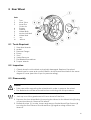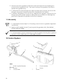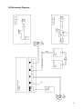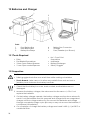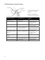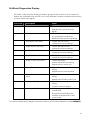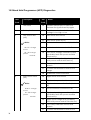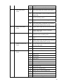
1
Invacare® MirageTM Service manual Introduction • This manual provides basic details to enable the Invacare® MIRAGETM Wheelchair to be maintained. It is not intended to be a comprehensive maintenance guide/policy, but is intended for use by competent personnel to enable the chair to be adequately maintained. • The wheelchair is manufactured by: INVACARE Ltd South Road Bridgend Industrial Estate Bridgend Mid-Glamorgan CF31 3PY Sales Telephone: Sales Fax: Technical Services Fax: Email: Web: 01656 647327 01656 649016 01656 753299 [email protected] http://www.invacare.com • For TECHNICAL ADVICE, repairs, servicing, contact Technical Services. For SPARE PARTS orders contact Sales. • Quote the following details at all times: o Part Number (see Spare Parts Catalogue) o Description o Quantity required o Serial Number o Chair Type 1 Policy INVACARE Ltd Policy is as follows: Repairs to any component other than those detailed in this manual are not covered. Repairs to any tube metal work is not generally permitted without express permission of INVACARE Ltd. All fasteners i.e. bolts, Nyloc nuts, and any fastener showing damage must be renewed. • • Under no circumstances attempt to repair a crash damaged chair. Contact Technical Services for further Information. • Alterations to the wheelchair which occur as a result of incorrectly or improperly executed maintenance or overhaul work lead to the exclusion of all liability on the side of INVACARE. • We reserve the right to make any alterations on the grounds of technical improvements. • Information about operation or about general maintenance and care work should be taken from the wheelchair Operating Manual. Failure to comply with the above absolves INVACARE Ltd of liability. Note: Certain components will require removal to carry out maintenance. With the exception of fasteners, those components should be refitted. Notes on transport • If the wheelchair has to be shipped back to the manufacturer for major repairs, you should always use the original packaging for transport. • You should also include as accurate a fault description as possible. Information Symbols Note: This symbol identifies general information which indicates special points or simplifications in dismantling / reassembly. CAUTION: It is imperative that you observe any safety instructions identified with this symbol. This symbol identifies service work or tools required. 2 Contents 1 2 Layout of Modules components and controls Safety and assembly instructions 2.1 2.2 2.3 3 4 5 7 8 9 21 Tools Required ........................................................................................................................21 Inspection.................................................................................................................................21 Disassembly.............................................................................................................................21 Assembly..................................................................................................................................22 12 Control System 12.1 12.2 12.3 12.4 19 Tools Required ........................................................................................................................19 Inspection.................................................................................................................................19 Disassembly.............................................................................................................................20 Assembly..................................................................................................................................20 11 Gearbox 11.1 11.2 11.3 11.4 17 Tools Required: .......................................................................................................................17 Inspection.................................................................................................................................17 Disassembly.............................................................................................................................18 Assembly..................................................................................................................................19 10 Motor 10.1 10.2 10.3 10.4 15 Tools Required: .......................................................................................................................15 Inspection.................................................................................................................................15 Disassembly.............................................................................................................................15 Assembly..................................................................................................................................16 Chassis 9.1 9.2 9.3 9.4 13 Tools Required: .......................................................................................................................13 Inspection.................................................................................................................................13 Disassembly.............................................................................................................................14 Assembly..................................................................................................................................14 Rear Wheel 8.1 8.2 8.3 8.4 12 Tools Required: .......................................................................................................................12 Inspection:................................................................................................................................12 Disassembly / Assembly.........................................................................................................12 Castor Wheels and Forks 7.1 7.2 7.3 7.4 10 Tools Required: .......................................................................................................................11 Inspection:................................................................................................................................11 Disassembly / Assembly.........................................................................................................11 Upholstery Seat and Back 6.1 6.2 6.3 7 8 Tools Required: .........................................................................................................................9 Inspection:..................................................................................................................................9 Disassembly / Assembly...........................................................................................................9 Legrests 5.1 5.2 5.3 6 Before any inspection or repair work......................................................................................6 During dismantling/reassembly ...............................................................................................6 Before operation / after completion of work:..........................................................................6 Tools Required Armrests 4.1 4.2 4.3 5 6 22 Tools Required ........................................................................................................................23 Inspection.................................................................................................................................23 Disassembly.............................................................................................................................23 Assembly..................................................................................................................................24 3 12.5 12.6 Power Module Connector Orientation...................................................................................24 Schematic Diagram .................................................................................................................25 13 Batteries and Charger 13.1 13.2 13.3 13.4 13.5 13.6 14 Mechanical Brakes 14.1 14.2 14.3 14.4 4 29 30 General Drive Faults................................................................................................................30 General Troubleshooting........................................................................................................31 Shark Remote Information Gauge .........................................................................................32 Shark Diagnostics Display .....................................................................................................33 Hand Held Programmer (HPP) Diagnostics ..........................................................................34 17 Servicing Requirements 17.1 17.2 17.3 17.4 17.5 28 Tools Required ........................................................................................................................28 Inspection.................................................................................................................................28 Disassembly.............................................................................................................................29 Assembly..................................................................................................................................29 15 Replacing the Safety Belt 16 Fault Diagnostics 16.1 16.2 16.3 16.4 16.5 26 Tools Required ........................................................................................................................26 Inspection.................................................................................................................................26 Disassembly.............................................................................................................................27 Assembly..................................................................................................................................27 Inspection – Battery Charger .................................................................................................27 Battery Wiring Diagram...........................................................................................................28 36 Motors 9......................................................................................................................36 Controller and Joystick Remote 9 ...............................................................................36 Frame and Chassis 9...................................................................................................36 Batteries 9 ..................................................................................................................37 Battery Charger 9.....................................................................................................37 1 Layout of Modules components and controls 13 7 1 Main Frame 2 Motor Gearbox 3 Front Castor Wheel 4 Rear Drive Wheel 5 Legrest 6 Seat 7 Backrest 8 Armrest 9 Footplate 10 Shark Remote 8 10 6 12 4 5 11 11 Shark Power Module 12 Battery Boxes 13 Back Brace 2 1 9 20 3 15 16 14 17 14 Anti Tipper Wheels 15 Mechanical Brakes 16 Batteries (Removed) 17 Legrests (Removed) 18 Armrests (Removed) 19 Backrest (removed) 20 Folded Chassis 18 19 5 2 Safety and assembly instructions These safety instructions are intended to prevent accidents at work and it is imperative that they are observed. 2.1 Before any inspection or repair work Read and observe this repair manual and the associated operating manual. Caution: • Please note the heavy weight of some components. This applies especially to the removal of drive units and batteries. • The wheelchair must be switched off before removal of voltage-carrying components. • To do this, disconnect the batteries or remove them. • When making measurements on voltage-carrying components, avoid shortcircuiting the contacts. • Danger of fire and combustion! 2.2 During dismantling/reassembly Mark all current settings for the wheelchair (seat, armrests, backrest etc.), and the cable connecting plugs associated, before any removals. This makes reassembly easier. Caution: • Prop up the wheelchair with appropriate supports before starting the disassembly or assembly. • Never use standard nuts instead of self-locking nuts. . Note: • All plugs are fitted with mechanical latches which prevent release of the connecting plugs during operation. • To release the connecting plugs the latches must be pressed in. • When reassembling ensure that the latches are correctly engaged. 2.3 Before operation / after completion of work: Caution: • Check all fixings for tight fit. • Only operate wheelchair with correct tyre pressure. • Check electrical components for correct functioning, incorrect polarity of cables can result in damage to the electronics. • As a last check, always carry out a trial run. 6 3 Tools Required The following list gives the basic tools required to perform the maintenance procedures as illustrated in this manual. • • • • • • • • • • • • • • • • • • • • • • • • • • • • • • • 1 –Open Ended Spanner (7mm) 2 - Open End Spanner (8mm) 2 - Open End Spanner (10mm) 1 - Open End Spanner (11mm) 2 - Open End Spanner (13mm) 2 –Open Ended Spanner (17mm) 1 - Combination Spanner (19mm) 1 - Socket / Wrench (Shallow) (19mm) 1 – Cross Point Screwdriver (No 2) 1 – Cross Point Screwdriver (No 1) 1 - Flat Bladed Screwdriver (No 1) 1 - Nylon Mallet 1 - Torque Wrench 1 – Hex Wrench - (3mm) 1 – Hex Wrench - (4mm) 1 – Hex Wrench - (5mm) 1 - Knife 1 - Pressure Gauge 1 - Pump 1 - Drift 1 - Vice 1 - Valve Remover 1 - Multimeter 1 - Soldering Iron 1 - Pin Hammer 1 - Punch 1 - Pair Pliers 1 - Battery Discharge Tester 1 - HHP – Programmer 1 – Shark Programming Adapter 1 – Safety Goggles 7 4 Armrests 1 Armrest Top – Parts 1 2 3 4 Armpad Armrest top assembly Armpad screws Hand wheel 4 3 2 6 5 7 8 Armrest Lower – Parts 5 6 7 8 9 10 11 8 Skirt Guard Armrest Lower Tube Screws Skirt Guard Clamps Hand wheel Fixing Hand wheel Armrest Socket 9 11 10 4.1 Tools Required: 1. No 2 Cross Point Screwdriver 2. Flat Headed Screwdriver 4.2 Inspection: 1. Check that the skirt guard (5) is fixed and not physically damaged. If the panel is loose retighten the fixing screws (7), install a new panel if necessary. 2. Check for armpad (1) wear or damage. Replace if necessary. 3. Check for corrosion or paint damage to the bracketry and replace affected parts where necessary. 4.3 Disassembly / Assembly 1. Release the hand wheels (11) by rotating anti-clockwise. 2. Remove the top and lower armrest assemblies. Armrest Top Assembly 1. Remove the hand wheel (4). 2. Release the screws (3) with a No2 Cross Point Screwdriver to remove the armpad. Armrest Lower Assembly 1. Remove screws (7) with a Cross Point Screwdriver and take away skirt guard (5) and clamps (8). 2. Remove hand wheel (11). 3. Push fixing nut (9) into tube, to release plastic ring and remove both from armrest lower tube. 4. Repeat step 3, for armrest socket fixing nut. To re-assemble reverse the above steps taking care not to over tighten the fixing screws. 9 5 Legrests 1 3 Legrest Hanger – Parts 1 2 3 4 5 6 7 8 nut Hanger tube Hanger support Assy Hanger pivot Screw Screw Screw Hanger Lock Hanger Lock screw and 4 2 6 8 5 9 Standard Footplate – Parts 9 10 11 12 7 Lower footplate tube Footplate Screw Spacers 12 11 10 9 Adjustable Footplate – Parts 13 Adjustment Fixings 11 10 10 13 5.1 Tools Required: • • • • No 2 Cross Point Screwdriver 5mm Hex Wrench 10mm open ended spanner Mallet 5.2 Inspection: 1. Check that the footplate fits securely and operates correctly. 2. Check the operation of the footplate extension, clamping and adjustment screw (5). 3. Check the legrest for damage. 4. Check the hanger lock for damage or excessive wear (7). 5.3 Disassembly / Assembly 1. Operate the legrest release mechanism and remove from the wheelchair. 2. Release the height adjustment screw (5) and slide the lower footplate tube from the hanger. Use a mallet to gently tap the footplate if the tube will not move. Hanger 1. Remove screws (5) and (6) using a 5mm Hex Wrench. 2. Slide Hanger support assembly (2) over the end of the hanger tube (1). Gently tap with a mallet if it will not move. 3. Remove screw (4) with a No 2 Cross Point screwdriver and slide out hanger pivot (5) Note: It is NOT possible to disassemble the Hanger support (2). Footplates (Standard and Adjustable) 1. Remove screw (11) using a 5mm Hex Wrench. 2. Separate the footplate (10) from the lower legrest tube (9). 3. Take care not to damage the spacers (12) or adjustment fixings (13) if fitted. Hanger Locks 1. Remove fixing screw and nut (8) using a 10mm spanner. 2. Remove Hanger (7) Lock from wheel chair. To re-assemble reverse the above steps taking care not to over tighten the fixing screws. 11 6 Upholstery Seat and Back 3 2 1 Parts 1 2 3 4 5 6 7 Backpost Push Bar Hand wheel Screw Back Upholstery Seat Upholstery Screw 4 7 5 6.1 Tools Required: • 6 No 2 Cross Point Screwdriver 6.2 Inspection: 1. Check that the upholstery (5) (6) does not excessively sag, is unevenly stretched, worn or torn. Pay particular attention to buckles and straps inside tension adjustable back upholstery. 2. Check that all stitches are in good condition. 3. Check that all screws and washers (4) (7) are in good condition and are not burred. 6.3 Disassembly / Assembly 1. Release the hand wheels (3) by rotating anti-clockwise and remove push bar (2). Note: • Remove backrest from the wheelchair at this point if not already removed. 2. Remove screws (7) in order to remove seat upholstery (6). Pay attention to the fixing position for a Lapbelt (if fitted). 3. Remove screws (4) and slide off back upholstery. If a tension adjustable back is fitted, remove the back cushion first which is held on by hook and loop fastening strip. Note: • If a recliner back is fitted, it may be necessary to remove the gas spring and lower section of the back post to completely disassemble the upholstery 12 To re-assemble reverse the above steps, ensuring that the fixing holes in the upholstery and tubes are aligned. Take care not to over tighten the fixing screws. 7 Castor Wheels and Forks 8 2 Parts 1 2 3 4 5 6 7 8 9 10 11 Castor Fork Nut Fork stem Bearings Axle bolt Axle nut Bearing Castor wheel Tyre Inner tube Hub centre 7.1 Tools Required: • • • • • • • • 4 6 3 10 1 7 2 19mm Open Ended Spanner 19mm Socket / Wrench 13mm Open Ended Spanner x 2 Flat Bladed Screwdriver Mallet Pressure Gauge Pump Drift 9 11 5 7.2 Inspection 1. Check castor wheels are not buckled or physically damaged. Replace if required. 2. Check that the wheel bearings (7) run freely without excessive play. 3. Check that the castor wheel and fork nuts (2) are tight. 4. Check that the castor forks (1) are bent or damaged. 5. Check the crown/castor fork bearings (4) for wear and correct adjustment. 6. Check tyres for wear and correct inflation. Both wheels should show the same degree of wear (see side of tyre pressure rating). For tyre fitment see rear tyre section. 13 7.3 Disassembly 1. Remove castor socket cap with flat bladed screw driver, hold the lower fork stem nut (2) secure with 19mm spanner and remove the upper fork stem nut (2). 2. Gently tap the threaded end to the fork stem (3) with a mallet taking care not to damage the threads. Remove the castor fork assemblies 3. Lever out the top fork bearing (4) carefully, using the fork stem as a lever. Take care not to damage the threads. 4. Remove the lower fork bearing (4) using a drift and a mallet, tapping gently to avoid damaging the bearing. 5. To remove the castor wheels undo the axle nut (6) with a 13mm spanner using a second spanner at the other end of the axle bolt (5) to lock against rotation. Remove the axle bolt and remove the wheel from the fork. 6. Remove the bearings (7) by hand. 7.4 Assembly 1. To reassemble the wheel reverse step 5 & 6, but adjust tightness of nut until the wheel runs freely to a gradual halt. Note: • If the wheel stops abruptly, loosen the castor axle nut. • If the wheel wobbles (side play), tighten the castor axle nut enough to allow free spinning without side play. 2. Insert the fork stem bearings (4) using a mallet and drift across the bearing to prevent damage. 3. Start at the bottom and place the threaded end of the fork stem (3) through both bearings (4) and into the castor fork socket. 4. Locate fork stem nut (2) on the threaded end of the stem and tighten with a 19mm spanner just enough to allow the fork to swivel freely. 5. To check for correct tightness, perform the following test: • • Tip chair backwards and rest the push handles on the floor (remove the battery boxes first). Raise castor wheel towards ceiling, then gently push downward to either side. The wheel and fork should freely rotate down and hang straight towards the floor after a pendulum-type swing. Note: 14 • If the wheel stops angled to one side, loosen the fork stem nut slightly. • If the wheel continues to swing to both sides (like a pendulum), tighten the fork stem nut slightly. • Check the bearings for excessive play by gently rocking the fork assembly. 8 Rear Wheel Parts 1 2 3 4 5 6 7 8 9 10 Tyre Inner Tube Inner Rim Outer rim Screws Washer Wheel Bolts Motor shaft bolt Wheel Hub Key Washer 8.1 Tools Required: 1. 2. 3. 4. 5. 6. 7. 8. 5mm Hex Wrench Mallet Pressure Gauge Pump Vice Valve Remover Flat Bladed Screwdriver Torque Wrench 8.2 Inspection 1. Check wheel is not buckled or physically damaged. Replace if required. 2. Check tyres for wear and correct inflation, both wheels should allow the same degree of wear (see side of tyre for pressure rating). 8.3 Disassembly Caution: • Take care while supporting the wheelchair in order to remove the wheel. • The Batteries should be removed before continuing with this procedure. 1. Jack up one of the gearboxes to lift one wheel off the floor. 2. Remove the four Wheel Bolts (6) securing the Wheel to the Wheel Hub (8) using a 5mm Hex Wrench. Remove the Wheel. 3. Deflate the tyre (1), locate, loosen and remove Socket Head Cap Screws (4) securing the two halves of the Wheel Rims (3) together using a 5mm Hex Wrench. 15 Caution: • Ensure the tyre is fully deflated before attempting to separate to the two halves of the Wheel Rims. 4. Remove the tyre (1) and tube (2). 5. To remove the Wheel Hub from the Axle Shaft locate loosen and remove the Motor shaft Bolt (7) and washer (5) that secures the Wheel Hub to the Axle Shaft using a 5mm Hex Wrench. 6. Gently tap the end of the Axle Shaft with a mallet and pull the hub (8) off the gear box shaft (take care not to loose the key (9) located in the gearbox shaft). 8.4 Assembly 1. Re-fit the Wheel Hub (8) to the gearbox shaft ensuring alignment of the keyway of the wheel centre to the key (9) fitted to gearbox shaft. Gently tap the wheel centre with a mallet until the threads can be seen inside the shaft. 2. Fit the motor shaft bolt (7) using a 5mm Hex Torque Wrench, ensuring that the washer (5) has been fitted, to the gearbox shaft. Note: • Torque rating of rear wheel bolt = 35 – 40Nm. 3. Locate tyre (1) and tube (2) to the face of the inside Rim (3) that has the hole for the valve to sit in, slightly inflate the tube. 4. Locate the other half of the Wheel Rim (3) in position, insert Socket Cap Screws (4) in position and proceed to tighten the screws. Ensure the inner tube is not trapped between the Wheel Rim halves. 5. Tighten securely Socket Head Cap Screws (4) using a 5mm Hex Wrench. 6. Inflate to the correct pressure as indicated on the Tyre Side Wall. 7. Position Wheel on Wheel Hub, locate and tighten the four Wheel Bolts (6) using a 5mm Torque Hex Wrench Note: • 16 Torque rating of rear wheel bolt = 35 – 40Nm. 9 Chassis 10 9 7 16 6 15 2 8 1 11 5 3 13 14 4 12 Parts : 1 Anti Tipper 2 Anti Tipper Socket 3 Side Frame LH 4 Hanger Bracket Fittings 5 Control Module Bracket 6 Seat Saddle 7 Seat Clamp 8 X-Brace (Seat Frame) 9 10 Battery Rail Rear Tie Down Clamp 11 Seat Stay 12 Plastic Side Frame 13 14 15 Side Frame RH U Bracket Handwheel 16 Backrest Insert 9.1 Tools Required: • • • • 8mm Open Ended Spanner x 2 10mm Open Ended Spanner x 2 13mm Open Ended Spanner x 2 17mm Open Ended Spanner x 2 • • • • 4mm Hex Wrench 5mm Hex Wrench Flat Bladed Screwdriver Mallet 9.2 Inspection 1. Check all tubing for misalignment, damage or bending of the frame or crossbar assembly. 2. Check that no misalignment is present at the castor mount area (castor fork and socket). 3. Check all brazed/welded joints for fractures or damage. Check the paint finish for damage. 17 4. Check the crossbar assembly is not damaged (pivot bolt should not be overtightened). 5. Check that the chair folds easily and that the crossbar pivots and folding mechanisms operate correctly. 9.3 Disassembly Note: • Remove batteries, backrest, legrest and armrest before proceeding with the following. It is optional to remove the wheels or motors before proceeding with the following. • See Section 11 for information on how to remove motor gearbox. 1. Push buttons on the side of anti tipper socket (2) and remove anti tipper (1). 2. The anti tipper bottom section may be removed from the tube by using 2 x 8mm open ended spanners and completely removing the bolt. 3. The anti tipper sockets (2) can be removed by using a 10mm open ended spanner and a 4mm Hex Wrench. Completely remove the bolt and slide out anti tipper socket from the side frames (3 and 13). 4. Remove hand wheel (15) and withdraw backrest insert (16) 5. If the seat clamp (7) is locked, unlock both right and left hand side and fold wheelchair frame. 6. Remove the Hanger Bracket (4). Use a 10mm open ended spanner and 5mm Hex Wrench to completely remove the 2 socket head screws in the side frames and the bottom section of the seat clamp (7). Use a 4mm Hex Wrench and a 10mm open ended spanner to remove the front seat saddle (6). Slide hanger bracket out from the side frame. 7. Use a flat blade screw driver to carefully lever out the plastic frame fittings (12). 8. Locate X Brace (8) and seat stays (11). 9. Using a 4mm Hex Wrench and 10mm open ended spanner, remove the bolts which clamp the U brackets (14), seat stay (11) and side frames (13 and 3). Remove the U bracket (14). 10. Locate the Large Bolts at the bottom of each side of the X Brace (8). Remove the bolts using 2 x 17mm open ended spanners. 11. Remove the X Brace (8) from the side frames (3 and 13). 12. The X Brace (8) may be further disassembled. 18 • Push the bearings out from the short bottom tubes of the X Brace. • The Seat Stays (11) may be removed by using 2 x 10mm open ended spanners and removing the bolt and spacer which supports them. • The X Brace centre pivot may be disassembled by using 2 x 13mm open ended spanners and removing the bolt and spacers. • Remove the Seat Clamp (7) by using a 10mm open ended spanner and 5mm Hex Wrench. 13. The battery rails (9) can be removed by using 2 x 13mm open ended spanner (at the rear) and a 13mm open spanner at the front positions. Completely withdraw the rear bolt to remove the rear tie down clamp (10) and spacers. 14. The rear seat saddles (6) can be removed using a 10mm open ended spanner and 4mm Hex Wrench. 9.4 Assembly To re-assemble reverse the above steps, ensuring that all fixing holes in are aligned. Take care not to over tighten the fixing screws. 4 10 Motor 6 5 1 Parts : 1 Electro Magnetic Brake Brush Connector Motor Complete Commutator Motor End Cap 2 3 4 5 6 10.1 Tools Required • • • • • 3 2 No 1 Cross Point Screwdriver Flat Headed Screwdriver Soldering Iron Multimeter 3mm Hex Wrench 10.2 Inspection 1. Check motor assembly for damage. 2. Set multimeter to continuity test. Test continuity of motor leads (3) and electromagnetic brake leads (3). Brake resistance should read 50ohms - 80 ohms. 3. Check all joints for bad connection, cracked or dry solder joints and oxidation. 4. Check that all the brushes (2) can move freely in the brush guides with no obstruction (this can be easily done by pulling on the free brush feeder wire). 5. Check that all the brushes (2) are not chipped, cracked or worn. 6. Check that the brush (2) spring is positioned to the centre of the brush body to apply even force. Also check the brush spring tensions. 7. Check the condition of the brush (2) feeder wire and check that the termination screws are secure. 19 8. Visually inspect the commutator (5) for carbon deposits and remove with a soft brush. Note: • Ensure all the segments of the commutator are not bridged with conductive materials (i.e. Carbon or Copper) 10.3 Disassembly Caution • Disconnect the battery and the motor from the power module before proceeding with this instruction. 1. Remove the motor end (6) via the two cross point screws using a No 1 cross point screw driver. 2. Remove the two/three electro magnetic brake (1) fixing screws and remove the brake. 3. Remove the brush (2) feeder wire termination screws, release the brush springs and remove the brushes (2). 10.4 Assembly 1. To reassemble reverse the steps 1 to 3, taking care not to damage the brushes and ensuring correct alignment of the electro-magnetic brake. 2. Should there be fitting, scoring or wear then replace the Motor Unit. 20 11 Gearbox 4 Parts : 1 Gearbox Top 2 Gearbox Housing 3 Screws 4 Clutch Lever Upper 5 Clutch Lever Lower 6 Gearbox Top Gasket 7 Motor / Gearbox Gasket 8 Key 11.1 Tools Required • • • • • • 3 1 5 8 6 7 5mm Hex Wrench 8mm Open Ended Spanner Pin Hammer Punch Pliers Vice 2 11.2 Inspection 1. Check casing for cracks or damage or leakages. 2. Check Gearbox for noises (gears and bearings). 3. Check the declutching lever (4) and mechanism engages and disengages correctly. 4. Check that the output shaft of the gearbox is not damaged or bent. Remove the rear wheel and inspect the key (8) and keyway for wear and correct fitting. 11.3 Disassembly Caution: • Before proceeding with this instruction, remove the batteries from the wheelchair. • Remove the rear wheel from the gearbox (See Section 8). 1. Unplug the motor from the Power Module. Loosen and remove the six Screws (3) which hold the motor gearbox to the side frames of the wheelchair using a 5mm Hex Wrench. 21 2. Remove the motor gearbox and then locate and remove the remaining two screws (3) from gearbox lid (1). The lower housing of the gearbox (2) will now detach from gearbox top. 3. To dismantle the declutching lever upper (4) and lower (5) parts, knock out the fixing pin using a pin hammer and punch, separate the two halves. 4. To detach the gearbox from the motor, degrease the gearbox, remove the four fixing screws with an 8mm spanner, taking care not to deface or damage any gear teeth. Separate the gearbox and motor assembly. 11.4 Assembly 1. To reassemble reverse steps 2 to 5 ensuring correct motor to gearbox alignment is achieved. 2. Replace both gaskets (6 and 7) and re-pack the gearbox with ‘Shell Albida’ Grease (approx. 200g) Note: • To aid assembly it may be necessary to hold the gearbox housing (2) or gearbox top (1) in a vice. Take care not to damage the parts. 12 Control System 8 6 1 5 4 3 7 2 Parts : 1 Shark Joystick Remote Bracket 2 Screws 3 Control Arm 22 5 7 Power Module 6 Screw Screw 12.1 Tools Required • • • • • 3mm Hex Wrench 5mm Hex Wrench 7mm Open Ended Spanner 8mm Open Ended Spanner 10mm Open Ended Spanner 12.2 Inspection 1. Check for any physical damage to the outer case of Joystick Remote (1) and Power Module (5). 2. Inspect the rubber gaiter around the joystick knob (8) for any cracks, splits or perishing. This would enable water or moisture to access the unit. This may cause damage to the controller. 3. Check speed control knob is secure and its action is free and easy in rotation. 4. Check the wire harness from the joystick remote (1) is free from damage. 12.3 Disassembly Caution: • Before any work is carried out on the control system, ensure the Shark Power Module (4) is unplugged from the Batteries, and the Batteries are disconnected. Joystick Remote 1. Unplug the shark remote (1) from shark power module (4). 2. Depending on the type of control arm (3) fitted to the wheelchair, remove the screws (2) using either a 5mm Hex Wrench or 8mm Open Ended Spanner. Remove Joystick Remote 3. Remove the Joystick Knob (8) by firmly pulling upwards (if required). Power Module 1. Unplug the remaining connectors from the power Module. 2. Remove screws (7) using a 3mm Hex Wrench and a 7mm Open Ended Spanner in one position. The Power Module is now free. 3. To remove the power module bracket (5) from the wheelchair seat stays (see section 9) remove screw (6) using a 5mm Hex Wrench 10mm open ended spanner. 23 12.4 Assembly 1. To re-assemble reverse the above steps, ensuring that all fixing holes are aligned. Take care not to over tighten the fixing screws. Note: When fitting the joystick remote screws (2) be sure not to use a torque in excess of 2 NM. • 12.5 Power Module Connector Orientation A B C D Position : E A Motor Cable (LH Motor) B Battery Cable C Motor Cable (RH Motor) D NOT USED E Shark Joystick Remote Cable. All connectors are polarized and may only be fitted in one possible position 1 Part : 1 24 Battery wire Harness. R/H MOTOR / GEARBOX 1436632 M BRAKE SHARK REMOTE 1441611 DK-REMA05 NOT USED SHARK POWER MODULE 1433332 DK-PMA01 + 12V 40AH FRONT BATTERY BOX 1441620 1436694 - CABLE ASSY - 12V 40AH REAR BATTERY BOX 1441622 SOCKET CONNECTOR GREY L/H MOTOR / GEARBOX 1436633 M BRAKE BATTERY + RED BATTERY + RED RED CIRCUIT BREAKER CIRCUIT BREAKER BLUE RED SOCKET CONNECTOR SOCKET CONNECTOR RED CIRCUIT DIAGRAM REAR BATTERY BOX BLACK BLACK RED CIRCUIT DIAGRAM FRONT BATTERY BOX 12.6 Schematic Diagram 25 13 Batteries and Charger 1 2 3 4 5 Parts: 1 2 3 Front Battery Box Rear Battery Box Battery Box Straps 4 5 6 Battery Box Connector Charger Fuse / Breaker (not Shown) 13.1 Tools Required • • • • Pliers Flat Bladed Screwdriver 10mm Open Ended Spanner 11mm Open ended Spanner • • • • No 1 Cross Point Screwdriver Multimeter Battery Discharger Safety Goggles 13.2 Inspection Caution • Safety goggles should be worn at all times while working on batteries • Shock Hazard – take care not to allow any metallic items such as tools or jewellery touch between the battery terminals. 1. Check that the battery box case, leads, sockets, and batteries are not damaged. 2. Measure the battery voltages, the values must be the same +/- 0.2v. If not replace the batteries. 3. For the battery charger operate, the battery voltage must be shown above 8v each. If not the batteries must be removed and charged with an unregulated charger until the voltage reaches 9v. Re-connect the batteries and charge through a complete charge cycle (this may or may not recover the batteries, if not replace the batteries). 4. On completion of charge the battery voltage must read 14.20v (+/-) at 20°C or combined 28.4v. 26 13.3 Disassembly 1. Unplug the battery leads (4), and remove the battery wire harness (see section 12) if still present. 2. Undo the battery straps (3) 3. Unclip the battery box lids, remove the battery caps, and with a 10mm / 11mm spanner, undo the battery terminals. Remove the batteries from the cases. 13.4 Assembly To re-assemble, reverse steps 1 to 3 and charge the battery fully. Caution: • Take care of the battery polarities. Never cross polarities and always refit battery caps. If any wires or insulation is damaged, ALWAYS replace before use. 13.5 Inspection – Battery Charger 1. Check the charger case for physical damage. 2. Check the input and output leads and plugs for damage, cuts and wear. 3. Check that the charging, charge complete and power on lamps are operating correctly. 4. With an ammeter or a multimeter set to amp (range 10A) test the charging current. Note: • Ammeters must be connected in series with the battery circuit. • The current reading should read approximately 7amp at charge start and 0.2 amps at complete charge. 5. With a voltmeter or a multimeter, set to volts (range 30v) test the charging voltage at the battery supply (red + blue - ve wires). The reading should increase to 28.4v during charging. Note: • The battery charger is a sealed unit. Under no circumstances should it be opened. 27 13.6 Battery Wiring Diagram Circuit Breaker Rear Battery Box Red Red + Black Connector Grey - Connector Red + Blue Batter - Circuit Breaker Red Red Connector Red + - Black B tt Front Battery Box 14 Mechanical Brakes 1 2 3 Screw 4 5 6 2 4 Parts : Clamp Screws Anti Rotation 3 6 Handgrip Brake Shoe Brake fixing Rail 14.1 Tools Required • • 5mm Hex Wrench 4mm Hex Wrench 1 5 14.2 Inspection 1. Check that the brake mechanism has no excessive looseness, is not worn or damaged. 2. Check that the brake shoe is positioned correctly to provide maximum surface area contact on the tyre tread, and gives the positive brake hold. 28 Note: • The distance between the brake shoe and tyre should be 30-35mm approximately 14.3 Disassembly 1. Loosen and remove the Anti Rotation screw (3) with a 4mm Hex Wrench. 2. Remove the Brake and Clamp (1) by loosening the clamp screws (2) with a 5mm Hex Wrench. 3. Remove the Brake from the clamp and side frame. 4. Use a 5mm Hex Wrench to remove the brake shoe (5) from the brake assembly. 5. Use a 4mm Hex Wrench to remove the brake assembly from the brake fixing rail (6). 6. To remove the handgrip (4), pull upwards firmly. 14.4 Assembly 1. To re-assemble reverse steps 1 to 6 above. 2. Ensure the brakes give a positive hold on the tyre. If the handgrip (4) has been removed, refit it with a suitable adhesive. 15 Replacing the Safety Belt On both sides of the chair: • Loosen the clamp lever (1). • Pull out the backpost (2) and remove the safety belt. • Replace the safety belt and reassemble the backpost. • Fasten the clamp lever. 29 16 Fault Diagnostics 16.1 General Drive Faults Wheelchair will not start Drive motors disengaged Engage Motors Section 11.2 Batteries defective Replace Section 13 Flat Batteries Charge Section 13 Power supply interrupted Check battery Fuse / breaker Section 13.2 Check cable at joystick Section 12 Check cable at Power Section 12 Check battery boxes Section 12.2 Assess error Section 15.4 Replace motor / check Section Batteries Check wiring / replace Section 13 Charger Check / replace Section 13.5 No display on joystick remote Flash code on remote Flash code on remote Wheelchair judders in drive Drive unit defective Cannot charge batteries 30 Wheelchair runs too slowly Remote Replace Section 12.3 Power module defective Power module defective Section 12.3 Batteries Check / replace Section 13.2 16.2 General Troubleshooting Symptom Check / Action ON/OFF button pressed to ON, Joystick lights do not light up wheelchair does not move. • Are the battery cables connected ? • Is the joystick cable connected ? • Are the batteries disconnected ? • Are the batteries completely flat ? • Is the fuse / circuit breaker open ? • Are one or both motors disengaged (freewheel mode) ? • Is the Shark remote in Lock Mode? (See user guide). Battery Charge indicator shows low battery. Wheelchair moves slowly and does not respond well to joystick movement. • Are the batteries discharged to the critical level ? Batteries will not accept charge. • Possible charger fault ? • Batteries are no longer serviceable ? ON/OFF lights up, wheelchair does not move or behaves erratically. 31 16.3 Shark Remote Information Gauge Horn Button Information Gauge Speed Dial Refer to the Information Gauge for the relevant flash ON/OFF Button 32 The following table gives the basic status of the Shark remote. Display Description This Means That ….. Notes All LED’s off Power is off All LED’s on steady Power is ON Less LED’s imply a reduced battery charge/ Left red LED flashing Battery charge is low Charge batteries as soon as possible. Right to Left LED chase Shark is being brought out of lock mode To unlock shark, press the horn button twice within 10 seconds. Left to right LED chase alternating with steady display Shark is in programming, inhibit or charge mode The steady LED’s indicate the current state of battery charge. Right green LED is flashing Speed Limit Mode All LED’s flashing slowly Out of neutral at power up condition detected Release the joystick back to neutral All LED’s flashing quickly FAULT mode See table below. 16.4 Shark Diagnostics Display The Flash code from the Shark information gauge is shown below. The number of flashes are indicated with all LED’s on for the relevant number of flashes followed by a pause, then Flash again. Flash Code Description Notes 1 User Fault Possible stall timeout or user error Release the joystick and try again 2 Battery fault Check the batteries and cabling Try charging the batteries Batteries may require replacing 3 Left Motor Fault (M2) Check the left motor connections and cabling. 4 Right Motor Fault (M1) Check the right motor connections and cabling. 5 Left Park Brake Fault Check the left park brake connections and cabling. 6 Right Park Brake Fault Check the right park brake connections and cabling 7 Shark Control Unit Fault Check the Shark communications bus wiring. Replace the control unit 8 Shark Power Module Fault Check Shark connections and wiring Replace the power module 9 Shark Communications Fault Check Shark connections and wiring Replace the Shark control unit 10 Unknown Fault Check all connections and wiring Consult a service agent 11 Incompatible Control Unit Wrong type of control unit connected. Ensure the branded power module matches that of the control unit. For further details and in depth information refer to the Shark Installation Guide GBK80047 33 16.5 Hand Held Programmer (HPP) Diagnostics Fault Description Code Sub Code 1 User Fault 00 Possible stall timeout or user error Release the joystick and try again 2 Battery fault 00 Batteries are too low to drive with or voltage is too high or low 3 Left Motor Fault (M2) 00 Left motor short circuit 01 Left motor open circuit 02 Left motor connection fault (short to B) 00 & 01 change motor 03 Motor terminal connected to B+ 02 – 08 change power 04 Left motor voltage consistency fault (probably fault with power module electronics). 05 Left motor bridge fault (probably fault with power module electronics). 06 Too many hardware current limit events 07 Current measurement offset out of range. 08 Hardware current limit fault 00 Right motor short circuit 01 Right motor open circuit 02 Right motor connection fault (short to B-) 00 & 01 change motor 03 Motor terminal connected to B+ 02 – 08 change power 04 Right motor voltage consistency fault (probably fault with power module electronics). 05 Right motor bridge fault (probably fault with power module electronics). 06 Too many hardware current limit events 07 Current measurement offset out of Note : module 4 Right Motor Fault (M1) Note : module 34 Notes range. 5 6 7 8 Left Park Brake Fault Right Park Brake Fault Shark Control Unit Fault Power Module Fault 08 Hardware current limit fault 00 Left park brake-drive time test failed 01 Left park brake output enabled when chair idle 02 Left park brake output did not enable when entering drive 03 Left park brake fault during power up test 04 Left park brake feedback low during drive (park brake short circuit) 00 Right park brake-drive time test failed 01 Right park brake output enabled when chair idle 02 Right park brake output did not enable when entering drive 03 Right park brake fault during power up test 04 Right park brake feedback low during drive (park brake short circuit) 00 Local remote fault (electronics, power button fault etc). 01 Joystick fault at remote 02 Speed pot fault at remote. 00 Power Module Fault 01 RAM fault 02 ROM fault 03 CPU fault 04 EEPROM fault 05 Watchdog fault 06 Stack fault 07 Software fault 08 Power up testing fault 09 Relay fault or Pre-charge fault 0A Bridge fault or Disable all fault 0B Electronics fault 0C Calibration settings fault 35 9 Shark Communications Fault 00 Loss of communications between remote and power module 01 Limp mode due to unreliable communications 10 Unknown Fault 00 Catch all fault output 11 Incompatible Control Unit 00 Wrong type of control unit connected. For further details and in depth information refer to the Shark Installation Guide GBK80047. 17 Servicing Requirements INVACARE recommends that routine servicing be carried out at six monthly intervals. The routine service consists of the following: 17.1 Motors • Inspect plugs for physical damage. • Inspect insulation for cracks and splits. • Check and clean brake. Resistance = Approx. 50 - 80 Ohms. • Inspect and clean brushes and commutator. • Check action and operation of clutch mechanism. 17.2 Controller and Joystick Remote • Check for physical damage to outer casings. • Inspect joystick shroud and gaiter for cracks and splits. • Check all switch operations, and LED’s. • Check joystick lead and plug ends for signs of cracks, wear or physical damage. • Check diagnostics to assure no faults present on systems. (Check information gauge, if flashing refer to section 15 diagnostics). 17.3 Frame and Chassis 36 • Inspect all fixtures and fittings for tightness and integrity. • Check front and rear wheel/axle bolts are tight. • Ensure that all upholstery screws are present and tight. Check surface of screw head for sharp edges. Clean seat and back upholstery. 9 9 9 17.4 Batteries • Check batteries for any signs of physical damage. • Check terminals for cracks or blackness. 9 Note: • Should batteries become suspect, use battery discharge tester by Astra-Tech (Model DC39) to test capacity and runtime. 17.5 Battery Charger • Check for physical damage of casing. • Check all LED’s are operational. • For testing the battery charger, see section 13 Batteries and Charger. 9 37 UK INVACARE® INTERNATIONAL: 38 Mobitec Mobilitätshilfen GmbH Herzog Odilostrasse 101 A-5310 Mondsee Austria Fax: @: @: WWW: +43 - 6232 - 55 35 0 +43 - 6232 - 55 35 4 [email protected] [email protected] www.mobitec-austria.com Invacare® n.v. Autobaan 22 B-8210 Loppem (Brugge) Belgium Fax: @: WWW: +32 - (0)50 - 83 10 10 +32 - (0)50 - 83 10 11 [email protected] www.invacare.be Mobitec Rehab AG Benkenstraße 260 CH-4108 Witterswil Switzerland Fax: @: @: WWW: +41 - (0)61 - 48 77 08 0 +41 - (0)61 - 48 77 08 1 [email protected] [email protected] www.mobitec-rehab.ch Invacare Aquatec Alemannenstraße 10 88316 Isny Deutschland Fax @: WWW: 0 75 62 / 7 00 - 251 08 00 / 6 73 81 72 [email protected] www.invacare-aquatec.de Invacare® A/S Sdr. Ringvej 39 DK-2605 Brøndby Danmark (Kundeservice): +45 - (0)36 - 90 00 00 Fax (Kundeservice): +45 - (0)36 - 90 00 01 @: [email protected] WWW: www.invacare.dk Invacare® SA c/ Areny, s/n Poligon Industrial de Celrà 17460 Celrà (Girona) ESPAÑA : Fax: @: WWW: +34 - (0)972 - 49 32 00 +34 - (0)972 - 49 32 20 [email protected] www.invacare.es Invacare® Poirier SAS Route de St Roch F-37230 Fondettes France : Fax : @: WWW: +33 - (0)247 - 62 64 66 +33 - (0)247 - 42 12 24 [email protected] www.invacare.fr Invacare® Ltd South Road Bridgend Industrial Estate Mid Glamorgan - CF31-3PY United Kingdom (Customer Service): +44 - (0)1656 - 664 321 Fax (Customer Service): +44 - (0)1656 - 667 532 @: [email protected] @: [email protected] WWW: www.invacare.co.uk Invacare Mecc San s.r.l. Via Dei Pini, 62 I - 36016 Thiene (VI) ITALIA Fax: @: WWW: +39 - 0445 - 38 00 59 +39 - 0445 - 38 00 34 [email protected] www.invacare.it Invacare Ireland Ltd. Unit 5 Seatown Business Campus Seatown Rd, Swords County Dublin Ireland Fax: @: +353 - 18 10 70 84 +353 - 18 10 70 85 [email protected] Invacare® AS Grensesvingen 9 Postboks 6230 N-0603 Oslo Norge (Kundeservice): +47 - (0)22 57 95 10 Fax (Kundeservice): +47 - (0)22 57 95 01 @: [email protected] WWW: www.invacare.no Invacare® B.V. Celsiusstraat 46 NL-6716 BZ Ede The Netherlands : Fax: @: WWW: +31 - (0)318 - 69 57 57 +31 - (0)318 - 69 57 58 [email protected] www.invacare.nl Invacare (Portugal) II Rua Estrada Velha, 949 4465-784 Leça do Balio Portugal : Fax: @: WWW: +351-225105946 +351-225105739 [email protected] www.invacare.pt Återförsäljare: Invacare® AB Fagerstagatan 9 S-163 91 Spånga Sverige (Kundtjänst): +46 - (0) 8 761 70 90 Fax (Kundtjänst): +46 - (0) 8 761 81 08 @: [email protected] @: [email protected] WWW: www.invacare.se Tillverkare: Invacare® Deutschland GmbH Kleiststraße 49 D-32457 Porta Westfalica Deutschland MÖLNDAL +46 - (0) 31 – 86 36 00 Fax: +46 - (0) 31 – 86 36 06 @: [email protected] LANDSKRONA +46 - (0) 418 – 285 40 Fax: +46 - (0) 418 – 180 89 @: [email protected] OSKARSHAMN +46 - (0) 491 – 101 40 Fax: +46 - (0) 491 – 101 80 @: [email protected] MIRAGE-V-01-UK 0104 1441763 39