1
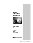
TD-700 FLUOROMETER SERVICE MANUAL July 1996 CONTENTS Page 2 Section 1 INTRODUCTION Section 2 PRELIMINARY CHECKS 3 Section 3 TROUBLESHOOTING GUIDE 5 A. B. C. D. E. F. G. H. I. J. K. L. M. N. Lamp (Fluorescent) Lamp Heater Fan Halogen Lamp No Response (no change in LCD readings) High Voltage Alarm (HV bad) Power Alarm (Low Pwr) Problem with Data Collection (RS-232) Keypad LCD Blank or Dark LCD “Flashing” Alarm Condition: General Diagnostic Checkpoints Replacing the NVRAM or EPROM Reset the System (NVRAM) to Default 5 7 8 9 10 11 12 13 13 14 14 15 16 19 Appendix 1 BOARD LAYOUTS A. S7-HV Board (Versions A & B) B. S7-HV Board (Versions C & later) C. S7-Main Board 20 20 21 22 Appendix 2 REPLACEMENT PARTS 23 7000-996 (July 22, 1996) Page 1 TD-700 Fluorometer Service Manual SECTION 1 INTRODUCTION This manual will help you troubleshoot and repair most of the common problems encountered with the TD-700 Fluorometer. The User's Manual that came with your instrument contains useful information about operational parameters, calibration, alarms, and diagnostics; please consult it if you have a problem at this level. Materials required: - Digital voltmeter; Standard electronics tools. 1. It has been our experience that what might at first appear to be an electronic failure often turns out to be operator error, or a loose connector or other simple malfunction. We strongly suggest you check the simple and obvious things first. (See SECTION 2.) 2. SECTION 3 describes troubleshooting by looking at the symptoms, including cases where an alarm is triggered. Section 3L describes general diagnostic checkpoints in alarm conditions. 3. You will find board layouts for locating components and checkpoints in Appendix 1. 4. A parts list for ordering replacement parts can be found in Appendix 2. 7000-996 (July 22, 1996) Page 2 TD-700 Fluorometer Service Manual SECTION 2 PRELIMINARY CHECKS WARNING ! ! ! High voltage up to 1000 volts may be present inside the instrument. Use caution in the area around connector JP1 on the S7-HV board. Some versions (A & B) of the TD-700 have large orange capacitors on the S7-HV board--these should be avoided. Troubleshooting should be performed in this sequence: a. Check for SOFTWARE problems; i.e., make sure operational parameters are correctly set; make sure calibration has been performed properly; check for correct standards, etc., if applicable. If sensitivity is an issue, or calibration seems ineffective or difficult, you might want to try resetting the system parameters to default (see Section N). b. Check for MECHANICAL problems; i.e., correctly installed/undamaged filters and lamp; correctly installed sample adaptor; sample compartment lid closed; lamp door shut and latched; power supply securely attached, etc. c. Finally, perform electronic diagnostics as found in this Service Manual. If you experience an apparent instrument failure, follow the following steps in order before going on to SECTION 3. 1. Verify that the power source at your site is working and appropriate for your instrument, i.e., 100 240 VAC. Check for blown fuses and check circuit breakers at your site. 2. Make sure the power supply is securely plugged into the socket on the back panel and that the instrument's power switch is ON. If the power plug into the unit is loose, then UNPLUG THE UNIT. Take a small screwdriver and insert it into the slot in the center pin of the power plug socket on the rear panel. Widen the gap so the plug holds more securely. To test, plug in the unit and turn power switch ON. Check the instrument's power supply; the green LED light on the power supply should be on when connected to the power source. 3. Make sure the lamp inside the sample compartment is working (see SECTION 3A or 3D). For further instructions, refer to the appropriate section in your user's manual. 4. UNPLUG THE INSTRUMENT FROM THE POWER SOURCE. Remove the instrument from the case: a. Using an Allen wrench, remove the 4 screws holding the lid on. Take off the lid. There will be a rubber or “paper” type gasket underneath the lid; take care not to damage it. b. Remove the 8 screws on the back panel. c. Remove the 10 screws from the bottom panel. 7000-996 (July 22, 1996) Page 3 TD-700 Fluorometer Service Manual d. Lift off the case. CAUTION! Take care not to damage the ribbon cable to the LCD/keypad when removing the case. There is a second rubber or “paper” type gasket underneath the case on top of the sample chamber opening; take care not to damage this gasket. 5. Visually and manually check for loose connectors. The latches on the ribbon cable connectors are secured as a precaution with RTV, but they have been known to pop open. Visually and manually check to see that wires are seated in their connectors. The connectors are secured as a precaution with RTV, but wires have been known to slip out. Visually and manually check for broken wires. CAUTION: If the HV wire (white wire on the end of connector JP1) is broken, and your instrument is the version with the orange capacitors, discharge it BEFORE you examine it or you may receive a shock. To discharge, connect an insulated wire to the chassis and press the other end of the wire to the HV wire pad on the PCB. 6. Visually and manually check for loose integrated circuits (IC). Are the IC's snugly pressed into the IC sockets? 7. Check for any moisture on the printed circuit boards (PCB's) or on the components. If you find moisture, use a fan to dry the PCB's. 8. Check for corrosion on the printed circuit boards (PCB's) or on the components. If corrosion is found: a. TURN OFF THE INSTRUMENT!! b. Use a fine wire brush to remove corrosion. c. Use isopropyl alcohol to remove any residue. Note that the areas underneath the components, the sockets and connectors, may be corroded if there is moisture. The chips on the LCD are especially susceptible to corrosion. If corrosion is extensive, or if the IC's or sockets are affected, it is probably best to replace the board. 9. Check for burned areas on the printed circuit boards (PCB's) or on the components. If there are black areas (clearly burned) then components may have to be replaced and/or traces may have to be reconstructed with wires. If damage is extensive, it is probably best to replace the board. 10. To retest, plug the instrument in (BE CAREFUL OF HIGH VOLTAGE POINTS). Turn it on using the power switch on the rear panel. If the instrument still does not work properly, go on to SECTION 3. 11. To reassemble the instrument: a. Make sure the first rubber or paper gasket is undamaged and correctly in place on top of the sample chamber opening. Be sure all wiring and ribbon cable connectors are inside the unit, then carefully replace the case, taking care not to hang up on any wiring. b. Replace and loosely tighten the 10 bottom panel screws and the 8 rear panel screws. c. Make sure the second rubber or paper gasket is undamaged and correctly in place on top of the case over the sample chamber opening. d. Replace the lid and the 4 screws. Tighten snugly, but do not overtighten. e. Finally, tighten snugly the 10 bottom panel screws and the 8 rear panel screws, but do not overtighten. 7000-996 (July 22, 1996) Page 4 TD-700 Fluorometer Service Manual SECTION 3 TROUBLESHOOTING GUIDE WARNING ! ! ! High voltage up to 1000 volts may be present inside the instrument. Use caution in the area around connector JP1 on the S7-HV board. Some versions (A & B) of the TD-700 have large orange capacitors on the S7-HV board--these should be avoided. A. LAMP (FLUORESCENT) WARNING ! ! ! • Use caution when handling the lamp; it may be hot (60°C). • Do not look at a lit lamp without eye protection (safety glasses); UV light can injure your eyes. The lamp is located inside the lamp compartment, accessible from the rear panel. a. To access it, pull on the two black release latches on the rear panel. Remove the lamp by grasping it (CAUTION: may be HOT), turning it 90°, and sliding it out to your right and toward you. b. Note that there is an override switch that prevents the lamp from lighting when the lamp access panel is removed. For some tests, this switch must be held in the "ON" position (pushed in). Use a pencil to hold it in the "ON" position. c. It is possible for the lamp to appear to be on, yet still need replacing. The lamp should light throughout the entire length, and should not be flickering. See Figure 1 for an ohm-check of the lamp. d. There are two lamp sockets (top and bottom). Each socket has two contact posts. Test the lamp socket voltages with the lamp removed; override switch pushed in; unit plugged in and power ON. See Table 1 for lamp socket voltages. Connect the negative (-) lead of the voltmeter to the instrument chassis; touch the positive (+) lead to the checkpoint. Figure 1. Ohm Check of Lamp 10 - 30 ohms across 2 pins Open circuit, end to end Table 1. Lamp Socket Voltages Socket Voltage* JP1 Wire Top (back) Top (front) Bottom (back) Bottom (front) 45-50 VDC 0 VDC 0 VDC 0 VDC Black White Red Green * Lamp removed; power ON; override switch pushed in 10 - 30 ohms across 2 pins 7000-996 (July 22, 1996) Page 5 TD-700 Fluorometer Service Manual A. LAMP (FLUORESCENT) (Continued) 7000-996 (July 22, 1996) Page 6 TD-700 Fluorometer Service Manual B. LAMP HEATER (FLUORESCENT LAMP) Heater is deactivated if the lamp is not on or if the halogen lamp is used. 7000-996 (July 22, 1996) Page 7 TD-700 Fluorometer Service Manual C. FAN 7000-996 (July 22, 1996) Page 8 TD-700 Fluorometer Service Manual D. HALOGEN LAMP WARNING ! ! ! Use caution when handling the lamp; it may be hot. Do not touch the lamp bulb with an ungloved hand; oils from your hand will affect bulb's transmittance and will reduce the life of the lamp. The lamp is located inside the lamp compartment, accessible from the rear panel. a. To access it, pull on the two black release latches on the rear lamp door panel. b. Power jack must be plugged in inside the lamp compartment for the fan to operate. 7000-996 (July 22, 1996) Page 9 TD-700 Fluorometer Service Manual E. NO RESPONSE (NO CHANGE IN LCD READINGS) 7000-996 (July 22, 1996) Page 10 TD-700 Fluorometer Service Manual F. HIGH VOLTAGE ALARM (HV BAD) WARNING ! ! ! High voltage up to 1000 volts may be present inside the instrument. Use caution in the area around connector JP1 on the S7-HV board. Some versions (A & B) of the TD-700 have large orange capacitors on the S7-HV board--these should be avoided. 7000-996 (July 22, 1996) Page 11 TD-700 Fluorometer Service Manual G. POWER ALARM (LOW PWR) 7000-996 (July 22, 1996) Page 12 TD-700 Fluorometer Service Manual H. PROBLEM WITH DATA COLLECTION (RS-232) 7000-996 (July 22, 1996) Page 13 TD-700 Fluorometer Service Manual J. LCD BLANK OR DARK 7000-996 (July 22, 1996) Page 14 TD-700 Fluorometer Service Manual L. ALARM CONDITION: GENERAL DIAGNOSTIC CHECKPOINTS WARNING ! ! ! High voltage up to 1000 volts may be present inside the instrument. Use caution in the area around connector JP1 on the S7-HV board. Some versions (A & B) of the TD-700 have large orange capacitors on the S7-HV board--these should be avoided. If there is an alarm condition, check the obvious things first (see Section 2). Then, you may want to check the voltages on connector JP4 on the Main Board (power supply and signal information). To check these voltages: 1. Unplug the unit. 2. Remove the instrument from the case (see Section 2, #4). 3. For versions A & B ONLY of TD-700, you may have to remove the S7-HV board to access JP4. To remove it, remove the 4 nuts holding the board in place, including any plastic ties present. Carefully lift off the board and set it gently on paper or plastic (no conductive surfaces, such as metal). Versions C and later of TD-700 have a cutout so that JP4 can be accessed without removing the S7-HV board. 3. Plug in the unit and turn on the power. 4. Locate connector JP4 on the Main board. Pins are numbered from front to back, starting with Pin 1. Note that the numbers on the connector itself may be reversed, i.e., 10 = pin 1. 5. Connect the negative (-) lead of your voltmeter to the chassis; touch the positive (+) lead to the checkpoint. Check and record the voltages according to Table 2. Table 2. JP4 Diagnostic Checkpoints Description (front to back) Pin 1 Normal Voltage -5 ± 0.2V Pin 7 5 ± 0.2 V Pin 8 15 ± 0.5V Pin 9 -15 ± 0.5V Pin 10 2.000 ± 0.004 V Voltage Reading If voltages are not within normal range, return to manufacturer. If readings are not normal, it means: Pin 10: Problem with the 2 Volt Reference IC; Pins 1, 8, & 9: Problem with DC to DC Convertor; Pin 7: Problem with 5 Volt Voltage Regulator. 7000-996 (July 22, 1996) Page 15 TD-700 Fluorometer Service Manual M. REPLACING THE NVRAM OR EPROM It is possible, after some years use, that a warning screen may come up concerning the start-up test and non-volatile data (NEW/BAD NVRAM). This indicates that the fluorometer internal computer battery for data storage may be low. The instrument will still operate, but when the battery fails, every time it is turned off it will not retain instrument parameter and previous calibration settings. (The current battery has a 10-year life specification.) This situation can be solved temporarily by leaving the instrument ON at all times, until the NVRAM module can be changed. If it is turned off, instrument parameters will have to be reset and the instrument recalibrated. On rare occasions, the EPROM may be replaced in order to update the instrument to the latest version. INSTALLING THE NVRAM MODULE Refer to the S-7 Main Board Diagram in Appendix 1C to locate the NVRAM module. DO NOT TOUCH THE NVRAM PINS - static electricity can damage the NVRAM! Before handling new NVRAM, discharge static electricity by touching chassis of instrument. 1. UNPLUG THE INSTRUMENT!!! 2. Remove the instrument from the case: a. Using an Allen wrench, remove the 4 screws holding the lid on. Take off the lid. There will be a rubber or “paper” type gasket underneath the lid; take care not to damage it. b. Remove the 8 screws on the back panel. c. Remove the 10 screws from the bottom panel. d. Lift off the case. CAUTION! Take care not to damage the ribbon cable to the LCD/keypad when removing the case. There is a second rubber or “paper” type gasket underneath the case on top of the sample chamber opening; take care not to damage this gasket. 4. Now as you face the front of the instrument, locate the NVRAM module (to your left near front) on the S7-Main Board (nearest the bottom of the instrument). 5. Take a small flathead screwdriver and GENTLY pry the NVRAM module from its socket. Pry up the left side slightly, then the right side, alternating sides until the pins are clear of the sockets. Set the module aside. 6. Take the new NVRAM module, marked "MK48Z08B-XX". Locate the notch on the NVRAM module. The NVRAM module must be installed in the correct orientation, with the notch to your right with the front of the instrument toward you. CAUTION! Incorrect installation will damage the NVRAM. The S7-Main Board is marked with white lines that show the proper orientation: Line up this small box with the notch on the module 7. Install the new NVRAM Module into the empty socket. Examine the module before installing to make sure all pins are straight. Carefully line up the rows of pins with the rows of sockets. Then gently press the pins into the sockets. When you are sure all pins are properly seated, use the flat side of a screwdriver to press the module evenly all around, making sure it is in as far as it will go. 7000-996 (July 22, 1996) Page 16 TD-700 Fluorometer Service Manual 8. Make a visual check of the inside components to make sure no wiring is hung up and that everything appears to be secure. 9. Plug in the instrument and turn on the power. When the instrument is first powered up, a “New NVRAM” screen will be displayed. Check for normal operation by paging through screens, etc. 10. Reinstall the instrument in the case. Use care when reinstalling improper installation will result in poor performance! a. Make sure the first rubber or paper gasket is undamaged and correctly in place on top of the sample chamber opening. Be sure all wiring and ribbon cable connectors are inside the unit, then carefully replace the case, taking care not to hang up on any wiring. b. Replace and loosely tighten the 10 bottom panel screws and the 8 rear panel screws. c. Make sure the second rubber or paper gasket is undamaged and correctly in place on top of the case over the sample chamber opening. d. Replace the lid and the 4 screws. Tighten snugly, but do not overtighten. e. Finally, tighten snugly the 10 bottom panel screws and the 8 rear panel screws, but do not overtighten. INSTALLING THE EPROM Refer to the S-7 Main Board Diagram in Appendix 1C to locate the EPROM module. DO NOT TOUCH THE EPROM PINS - static electricity can damage the EPROM! Before handling new EPROM, discharge static electricity by touching chassis of instrument. 1. UNPLUG THE INSTRUMENT!!! 2. Remove the instrument from the case: a. Using an Allen wrench, remove the 4 screws holding the lid on. Take off the lid. There will be a rubber or “paper” type gasket underneath the lid; take care not to damage it. b. Remove the 8 screws on the back panel. c. Remove the 10 screws from the bottom panel. d. Lift off the case. CAUTION! Take care not to damage the ribbon cable to the LCD/keypad when removing the case. There is a second rubber or “paper” type gasket underneath the case on top of the sample chamber opening; take care not to damage this gasket. 4. Now as you face the front of the instrument, locate the EPROM module (to your left near the front edge of the board to the right of the NVRAM) on the S7-Main Board (nearest the bottom of the instrument). 5. Take a small flathead screwdriver and GENTLY pry the module from its socket. Pry up the left side slightly, then the right side, alternating sides until the pins are clear of the sockets. Set the module aside. 6. Take the new EPROM module. Locate the notch on the module. The module must be installed in the correct orientation, with the notch to your right with the front of the instrument toward you. CAUTION! Incorrect installation will damage the module. The S7-Main Board is marked with white lines that show the proper orientation: Line up this small box with the notch on the module 7000-996 (July 22, 1996) Page 17 TD-700 Fluorometer Service Manual 7. Install the new Module into the empty socket. Examine the module before installing to make sure all pins are straight. There are more sockets then there are pins, so the module should be installed with the pins on the un-notched end of the module inserted flush with the sockets on the side closest to the NVRAM. (This means that 2 sockets on each row will be empty on the right side of the module base.) Carefully line up the rows of pins with the rows of sockets. Gently press the pins into the sockets. When you are sure all pins are properly seated, use the flat side of a screwdriver to press the module evenly all around, making sure it is in as far as it will go. 8. Make a visual check of the inside components to make sure no wiring is hung up and that everything appears to be secure. 9. Plug in the instrument and turn on the power; the new version and date with appear on the “Title” screen. Check for normal operation by paging through screens, etc. 10. Reinstall the instrument in the case. Use care when reinstalling improper installation will result in poor performance! a. Make sure the first rubber or paper gasket is undamaged and correctly in place on top of the sample chamber opening. Be sure all wiring and ribbon cable connectors are inside the unit, then carefully replace the case, taking care not to hang up on any wiring. b. Replace and loosely tighten the 10 bottom panel screws and the 8 rear panel screws. c. Make sure the second rubber or paper gasket is undamaged and correctly in place on top of the case over the sample chamber opening. d. Replace the lid and the 4 screws. Tighten snugly, but do not overtighten. e. Finally, tighten snugly the 10 bottom panel screws and the 8 rear panel screws, but do not overtighten. 7000-996 (July 22, 1996) Page 18 TD-700 Fluorometer Service Manual N. RESET THE SYSTEM TO DEFAULT Resetting to system defaults may help if calibration is difficult or sensitivity is too high or too low, and calibrating does not seem to cure the problem. NOTE: This will completely reset instrument settings, including calibration, to default. After resetting, user settings will have to be entered again and a new calibration performed. 1. Turn the instrument power OFF then wait for few seconds, turn the power ON. At screen : TURNER DESIGNS T7-1A 03/95 XXX 2. Press < H > to screen : <ENT> - XXX.X fsu Setup & Cal 3. Press < ENT > to screen : 1. Setup 2. Calibration 4. Press < * > to screen : Input Turner ID : 5. Enter < 1962 >, then press < ENT > to screen: Lamp: ON HV: XXX X.XXX X.XXX 6. Press < ENT > twice to screen: Oper : XXX Hrs. 1 : RESET NVRAM 7. Press < 1 > to screen : 10 < 0 > - SYS data 8. Keep pressing < 0 > until you see screen : TURNER DESIGNS T7-1A 03/95 XXX 9. The instrument is completely reset. Calibrate the instrument. 7000-996 (July 22, 1996) Page 19 TD-700 Fluorometer Service Manual APPENDIX 1 BOARD LAYOUTS A. S7-HV BOARD (Versions A & B with orange capacitors; version is marked on the board) 7000-996 (July 22, 1996) Page 20 TD-700 Fluorometer Service Manual B. S7-HV BOARD (Versions C and later; version is marked on the board) 7000-996 (July 22, 1996) Page 21 TD-700 Fluorometer Service Manual C. S7-MAIN BOARD (located closest to the bottom of the instrument) 7000-996 (July 22, 1996) Page 22 TD-700 Fluorometer Service Manual APPENDIX 2 REPLACEMENT PARTS Contact the manufacturer for prices and additional parts. Part Description Part Number EPROM Module 005-0256 Halogen Bulb 7000-970 Keypad with TD-700 Overlay 7000-979 Lamp Heater PCB Assembly 7000-976 Lamp Socket (pair) 7000-977 LCD Display 7000-978 NVRAM Module 005-0460 On/Off Switch 7000-972 Power Cable Assembly (internal; 12V power/lamp) 7000-973 RS-232 Ribbon Cable (internal) 7000-971 S7-HV Board (PCB) 7000-975 S7-Main Board (PCB) 7000-974 7000-996 (July 22, 1996) Page 23