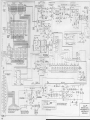
1
n®®
IM
INGLUDINe
PARTS LIST
CAUTION
SEE SAFETY NOTICE ON
INSIDE
H 000-006059
ORGAN SERVICE COMPANY
6475 JOLIET
ROAD
SUITE B-t
LaGRANGE ILLINOIS 60525
PHONE 708-352-8011
COVER SHEET
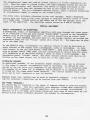
SAFETY NOTICE
Great care has bean taken In the design and manufacture of this product to assure that no
shock hazard exists on any exposed metal parts. Internal service operations can expose the
technician to hazardous line voltages and accidentally cause these voltages to appear on
exposed metal parts during repair or reassembly of product components. To prevent this, work
on these products should oniy be performed by those who are thoroughly familiar with the
precautions necessary when working on this type of equipment.
To protect the user,
required that all enclosure parts and safety Interlocks be rettored to
their original condition and the following tests be performed before returning the product to
the owner aftor any service operation.
Plug the
AC
It Is
cord directiy Into a line voltage
AC
receptacle (do not use an Isolation
transformer for this test) and turn the product on. Connect the network (as shown below) In
iine
senes with all exposed metal parts and a Known earth ground such as a water pipe or conduit.
Use an AC VOM of 5,000 ohms per volt or higher sensitivity to measure the voltage drop across
the network. Move the network connection to each exposed metal part (metal chassis, screw
heads, knobs and control shafts, escutcheon, etc.) and measure the voltage drop across the
network. Reverse the line plug and repeat the measurements. Any reading of 4 volts RMS or
more is excessive and indicates a potential shock hazard which must be corrected before
returning the product to the user.
VOM
AC SCALE
OK
I
n
I
.01
I
Mf
CERAMIC RF
BYPASS CAP
TEST CLIPS
TEST
PROBE
CONNECTEQ TO WQWN
EARTK ORQUHO
TO
EXPOSED HETAL PARTS
A
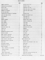
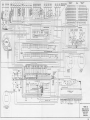
TABLE OF CONTENTS
PAGE
PAGE
GENERAL DESCRIPTION
ONE KEY DOES NOT PLAY
19
INSTALLATION AND MAINTENANCE
ONE NOTE IS WEAX
20
MUSICAL TERMS
PERCUSSION NOTES VEAK
2I
NOTES AND OCTAVES
PEDAL NOTE SOUNDS AT FULL VOLUME
21
HABMONICS OR OVERTONES
PEDAL NOTE SOUNDS FAINTLY
21
BOW THE ORGAN WORKS
HUM
21
REPLACING TUBES
22
CONSTRUCTION AND OPERATION OF COMPONENTS
7
MOTORS AND POWER SWITCHES
7
PROCEDURE FOR REMOVING PARTS
TONE GENERATOR
22
UPPER MANUAL KEY
22
MANUALS
8
LOWER MANUAL KEY
22
HARMONIC DRAWBARS
9
DRAWBAR CONTACT SPRING
23
PEDAL DRAWBAR
9
DRAWBAR OR DRAWBAR KNOB
23
PEDAL KEYBOAIU)
9
UPPER MANUAL
24
EXPRESSION PEDAL
10
LOWER MANUAL
25
CONTROL TABLETS
10
CONTROL PANEL ACCESS
26
PERCUSSION CONTROL TABS
10
PERCUSSION SWITCH ACCESS
26
VIBRATO TABS
11
GENERATOR
26
12
STARTING MOTOR
26
PILOT LIGHT
26
+
PRESET TABS
REVERBERATION-VOLUME SOFT TABS
,,.12
AMPLIFIER ASSEMBLY
12
TAB SWITCH
26A
MANUAL SECTION OF AMPLIFIER
13
VIBRATO LINE BOX
26A
PEDAL SECTION OF AMPLIFIER
I
PEDAL KEYBOARD
26A
INTERMEDIATE SECTION OF AMPLIFIER
15
EXPRESSION PEDAL
26A
OUTPUT SECTION OF AMPLIFIER
,.,. 15
PRESET PERCUSSION UNIT
77
78
PERCUSSION SECTION OF AMPLIFIER
16
SELECTOR SWITCH
POWER SUPPLY
17
HARMONIC BUSBAR SWITCHING
TUBE SOCKET VOLTAGES
H
UPPER MANUAL
78
REVERBERATION AMPLIFIER
17
MODE SWITCH
79
SPECIAL EQUIPMENT
18
FREQUENCY DIVIDER
79
RADIO, PHONOGRAPH, OR MICROPHONE
18
CYMBAL AND BRUSH
80
EXTENSION SPEAKER
18
BRUSH KEi'ING
80
EAR PHONES
IS
CYMBAL KEYING
80
SPECIAL POV,^R SOURCES
19
CXMBAL-BRUSH AMPLIFIER AND NOISE GATE
80
19
CH.\NnES
PRACTICAL SERVICE SUGGESTIONS
ORGAN DOES NOT PLAY
.
AM
REVISIONS
IiKTALLr\TION AND MAINTENANCE
19
1
&
REIT- SPLIT
78
81
BACK COVER
....
LIST OF FIGURES AND ILLUSTRATIONS
FIGURE
PAGE
1
Front View of Console - Model M
27
2.
Front View of Console - Model M-2
28
3.
Back View of Console - Model M, M-2
29
4.
Front View of Console - Model M-3
30
5.
Back View of Console - Model M-3
31
6.
Front View of Console - Model M-lOO
32
7.
Back View of Console - Model M-lOO
33
8.
Block Diagram - Model M
34
9
Block Diagram - Model M-2
34
Block Diagram - Mcdel M-3
35
11.
Block Diagram - Model M-lOO
35
12.
Typical Tone Generator
36
13.
Magnet Locations on Tone Generator
14
Generator Cover - Model M
37
14A.
Generator Cover - Model M - Serial 15083 and Up
37
15.
Generator Cover - Model M, M-2, M-3
38
16
Generator Cover - Model M-3
39
17.
Generator Cover - Model M-lOO
40
18.
Manual Wiring Chart
41
19.
Drawbar Assembly
42
20.
Pedal Keyboard Assembly - M, M-2, M-3
42
21.
Pedal Keyboard Assembly - M-lOO
43
22.
Fundamental Vibrato System - M
43
23.
Vibrato System - Model M - 13509 and below
44
24.
Vibrato System
Model M - 13509 and above
44
25.
Fundamental Vibrato System
10.
,
-
."
-
90485 and above
- M-2,
M-3
.
,
,
.
36
45
LIST OF FIGURES AND ILLUSTRATIONS CONTINUED
PAGE
FIGURE
26.
Fundamental Vibrato System - M-lOO
46
27.
Vibrato Line Box-Model M, M-2
46
28.
Vibrato Line Box - M-3
47
29.
Vibrato Line Box - M-lOO
47
30.
Vibrato Scanner
47
31.
Vibrato System M-2
32.
Vibrato System M-2 - Serial 25254 and above
48
33.
Manual Hold Down Screws
49
34.
Pictorial - Model M Amplifier
50
35.
Pictorial - Model M Amp.
- Serial 8411 and above
51
36.
Pictorial - Model M-2 Amp. Serial 19000 and above
52
36A.
Pictorial - Model M-3 Amp (Partial)
53
36B.
Pictorial - Model M-3 Amp
54
37.
Schematic AO-35 Reverberation Amp M-lOO
55
38.
Schematic AO-44 Reverberation Amp M-lOO
56
38A.
Schematic AO-44 - See Serial Numbers
57
39.
Schematic AO-66 Reverberation Amp (Later Model M-lOO)
58
40.
Schematic Model M
59
41.
Wiring Diagram Model M
60
41A.
Wiring Diagram Model M - Serial 15083 and above
61
42.
Schematic Model M-2 - 19000 and above
62
43.
Wiring Diagram Model M-2
Serial 19000 and above
63
43A.
Wiring Diagram Model M-2 - Serial 25254 and above
64
44.
Schematic Model M-3
65
-
Serial 19000 to 22253
(M,
-
48
M-2, M-3)
F
44A.
Schematic Model M-3 Serial 90485 and above
66
44B.
Schematic Model M-3 - Serial 109466 and above
67
45.
Wiring Diagram Model M-3
68
..
LIST OF FIGURES AND ILLUSTRATIONS CONTINUED
FIGURE
PAGE
45A.
Wiring Diagrams Model M-3 - Serial 90485 and above
69
46.
Schematic Model M-lOO with AO-35 and AO-29
70
47-
Schematic Model M-lOO with AO-44 and AO-29
71
48.
Schematic Model M-lOO with AO-66 and AO-67
72
49.
Wiring Diagram M-lOO with AO-35 Amp
73
50
Wiring Diagram M-lOO with AO-44 Amp
74
51.
Wiring Diagram M-lOO Control Panel
,
73
i
M-IOOA SUPPLEMENT
52.
M-IOOA Percussion Kit Wiring Diagram
82
53.
Brush and Cymbal Wiring Diagram with AO-66 Amp
83
54.
Brush and Cymbal Wiring Diagram with AO-44 Amp
°^
55.
Schematic - Percussion Preset Unit
85
56.
Schematic Diagram Model M-IOOA
87
57
Wiring Diagram Model M-IOOA
88
58.
Percussion Kit Circuit Board Component Layout
89
4
.
GENERAL DESCRIPTION
The Hammond Organ "m" Series Spinet Consoles are completely self contained, requiring no external tone cabinet.
All Models have two (2) manuals of forty-four
(44) keys each, a 12 (M, M-2, M-3) or 13 (M-lOO) note pedal keyboard, and an expression (or swell) pedal for controlling the volume. All tones are produced
by electro-magnetic tone generators and electrically amplified.
Selection of tone
colors is made by adjusting eighteen(18) drawbars, and other characteristics of
the music are adjusted by means of tilting control tablets and tab switches.
A
push button and a toggle switch or two toggle switches located in the front of
the Console are used to turn on the organ.
Figures 1 thru 7 show the front and rear views of the "M" Series Models- The
rear views are shown with the dust covers removed.
Console rear panels are an
optional accessory and are not shown.
INSTALLATION AND MAINTENANCE
A card packed with the playing instructions or located in the bench gives full information on installing the organ, oiling, and packing for moving or shipment.
(See Back Cover)
MUSICAL TERMS
The service man who has had no musical training will find the following information helpful in studying the operation of the organ.
NOTES AND OCTAVES
Keyboard instruments are divided into '^octaves" of 12 keys or notes, each with
spven (7) ''naturals" (white keys) and five (5) "sharps" or "flats" (black keys)
in a definite sequence.
Black keys occur in groups of two and three in each
octave and offer a convenient way to identify the notes of the octave. Technically there is no difference between a black key and a white one, since each key
has a frequency 1.059 times the frequency of the next one below it.
Each note has a frequency exactly one half that of the corresponding note in the
next higher octave.
Each white key is called by a letter for A to G and these
letters are known as "note of the musical scale", A black key may be called a
"sharp"of the notes below it or a '^flat" of the notes above it; for instance, the
black key between C and D may properly be called Cif (Sharp)
or D*^ (D flat).
HARMONICS OR OVERTONES
Any musical note has a definite fundamental pitch or frequency and also a certain
"tone quality" or "timbre" depending on its wave shape. A complex note is one
which includes not only a fundamental frequency but also one or more "harmonics"
or "overtones," each of which is an integral multiple of the fundamental frequency.
Such a combination is more pleasing musically than a note having only a single
frequency. The ear does not distinguish the harmonics independently but instead
identifies the note as a complex tone having the pitch of the lowest component,
or fundamental
,
.
HOW THE ORGAN WORKS
Most tone sources, such as strings, reeds or pipes, produce complex tones
The
Hammond tone producing mechanism, however, generates individual frequencies which
can be combined by means of harmonic drawbars to produce any desired tone quality.
The block diagrams in Figures 8 thru 11 show the chief components of the instruments.
,
.
Electrical impulses of various frequencies are produced in the "tone generator'^
which contains a number of "tone wheels" driven at predetermined speeds by a
motor and gear arrangement.
Each tone wheel is a steel disc similar to a gear^
with high and low spots, or teeth, on its edge (see figure 12). As the wheel
rotates these teeth pass near a permanent magnet, and the resulring variations
in the magnetic field induce a voltage in a coil wound on the magnet.
This
small voltage, when suitably filtered, produces one note of the musical scale,
its pitch or frequency depending on the number of teeth passing the magnet each
second.
A note played on either manual of the organ consists of a fundamental pitch and
a number of harmonics, or multiples of the fundamental frequency.
The fundament
al and eight harmonics available on each playing key are controllable by means
of drawbars.
By suitable adjustment of these controls the player may vary the
tone colors at will.
The M-lOO Console has several preset tabs which make several pre-selected tones available,
MODEL M
Mixed tones from the manuals are amplified and then pass through the vibrato
mechanism, the expression control, and additional stages of amplification before
reaching the loudspeaker
-
MODEL M-2i M-3i M-lOO
Mixed tones from either the upper or the lower manual may go through either the
"vibrato" channel or the "No Vibrato" channel, depending on the position of the
corresponding vibrato selector of "Vibrato Cancel" tabs.
(The upper manual is
called "Solo" on the selector tab of the M-2 and M-3 to indicate that it is
best suited for playing melody or solo parts of the music.) The tones are then
combined and passed through the expression control and additional stages of
amplification before reaching the speaker(s)-
MODEL M-3» M-lOO
Percussion tones are produced by borrowing a signal from the upper manual 2nd
harmonic drawbar, 3rd harmonic drawbar, or both, amplifying it, returning part
of the signal to the same drawbar, and conducting the balance of the signal
through push-pull control tubes where its decay characteristics are controlled.
The percussion signal is then combined with the signal from the manuals after
the vibrato system but before the expression control.
The control tubes are
keyed through the 6th harmonic key contacts and bus bar.
The pedal tones do not require drawbars for tone color variation, because they
are produced as complex tones by special tone wheels.
From the pedals these
tones go to a pedal amplifier, where the attack and decay characteristics are
controlled.
The single pedal drawbar adjusts the volume of the pedals relative
to that of the manuals, and the pedal signal than is combined with the signal
from the manual before passing through the expression control, but after the
vibrato system.
,
CONSTRUCTION AND OPERATION OF COMPONENTS
In reviewing this section refer to the schematic circuits of the entire organ
systems in the back of this manual.
Connections between components are shown in
the wiring diagrams and control assembly wiring drawings, also in the back of the
manual,
MOTORS AND POWER SWITCHES
The tone generator assembly in which all tones of the organ originate, is
driven at constant speed by a synchronous motor, located at the left side as you
look in at the back of the Console. Attached to it is the vibrato scanner.
As
the synchronous motor is not self-starting, it must be brought up to speed by
a starting motor at the opposite end of the generator.
The procedure for turning on the organ is as follows: Push the "start'' switch
up (M-3, M-lOO) or in (M, M-2) and hold it for approximately eight seconds.
This allows time for the starting motor to bring the generator up to slightly
above it synchronous speed- While still holding the "start" switch, push the
"run" switch upward to its "on" position. This turns on the synchronous motor
and at the same time introduc,es a resistor in series with the starting motor
to reduce its powerHold the "start" switch about four seconds longer and then
release it-
During this time the braking action of the synchronous motor, together with the
reduction in power of the starting motor, brings the system to synchronous
speed so that the synchronous motor can carry the load.
To turn off the. organ, push the "run" switch downward to the "off" position.
a
TONE GENERATOR
All tones of the organ originate as electrical signals in the tone generator
assembly.
The M, M-2 and M-3 contains 85 tone wheels while the M-lOO has 87,
Each of these wheels has various numbers of teeth, with suitable gears for driving them at various speeds from a main shaft extending along the center.
Each
pair of tone wheels is mounted on a shaft and between them is a bakelite gear
held between two coil springs, forming a mechanical vibration filter. As the
gear is not rigidly attached to the shaft, any pair of wheels which may be
stopped accidentally will not interfere with the operation of the others.
Adjacent to each tone wheel is a magnetized rod with a pick-up coil wound on
it.
These magnets extend through the front and back of the generator, and are
held by set screws which can be loosened in case adjustment is ever necessary.
Figure 13 shows where to find the magnet for any frequency number.
In this
drawing the dotted lines indicate frequencies whose tone wheels are on the
same shaft.
On top of the tone generator assembly are small transformers and condensers
forming tuned filters for the higher frequencies. They are not likely to need
replacing.
In case one filter becomes inoperative, both the transformers and
condenser must be replaced with a matched set from the factory.
Figures 14,
15
16 and 17 show the locations of these filters on the indicated models.
A
few frequencies use untuned filters consisting of coils alone.
»
The output frequencies of the tone generator are numbered for convenience, in
order of increasing frequency.
The lowest, number 1
is about 32 cycles per
second, and the highest, number 91, is about 6000 cycles per second.
Frequency
numbers 1 to 12 (1 to 13 on M-lOO) are used for pedals; numbers 13 to 17 (14 to
17 on M-lOO) are omitted; and numbers 18 to 91 are used for the manuals.
,
,
In case any generator frequency is weak or absent, refer to "Practical Service
Suggestions" for the procedure to be used in locating and correcting the trouble.
The output terminals of the generator consist of solder lugs mounted on the filThe freter transformers, to which the manual cable and pedals are connected*
quency numbers of all terminals are indicated in Figures 14, 15, 16 and 17.
MANUALS
Musical frequencies from the tone generator go through the manual cable to terminal strips on the two manuals and from them to the key contact springsEach of the two manuals has forty-four (44) playing keys, or approximately
3-1/2 octaves.
The two manuals do not cover exactly the same pitch range, but
they are arranged so that keys of like pitch are in line. Middle "C" is the first
C on the upper manual and the key in line with it on the lower manual.
Under each key are a number of contact springs (for the fundamental and harmonics of that key) which touch an equal number of busbars when the key is pressed,
(Some keys at the right end of each manual have fewer springs, as noted below)
All contact springs and busbars have precious metal contact surfaces to
avoid corrosion, and the manuals are sealed to exclude dust so far as possible.
In case a contact becomes dirty in spite of these precautions, a busbar shifter
(shown in Figures 3, 5,7) is provided in each manual to slide the busbars endwise and thus provide a fresh contact surface.
-
The busbar shifting mechanism is somewhat different on the M-lOO than on prior
models of the Hammond Orgam Models M, M-2 and M-3. Looking under the lower manual on the left hand end, a black wood end block will be observed.
One half inch
from the front of this block is a drilled hole.
Within this drilling is a small
metal tongue with a punched hole.
Using either long nose pliers or a hook, this
tongue can be moved in and out and it in turn moves the busbars.
The upper manual shifter is in a similar place, but requires removal of the generator dust
cover to gain access to it.
The key contacts are connected through resistance wires to the manual terminal
strips.
The manual wiring chart
Figure 18, shows how the contact of each key
are connected to the proper frequencies to supply the fundamental and harmonics
of that particular key.
The blank spaces indicate that no key contact is used,
inasmuch as the highest harmonics of the highest keys are above the range of the
tone generator and are not required.
Since the percussion control tubes in the
M-3 and M-lOO are keyed through the 6th harmonic busbar, the blank spaces in this
row have contacts connected to ground through resistance wires.
The busbars of each manual, each one carrying a certain harmonic, are wired to
the harmonic drawbars for that manual in the M, M-2, M-3 and through the "Drawbars" tab in the M-IOO-
8
HARMONIC DRAWBARS
The left group of eight (8) harmonic drawbars (Figure 19) is associated with the
lower manual, and the right group of nine (9) drawbars controls the upper manual.
By sliding these drawbars in and out, the organist is able to mix the fundamen^
tal and harmonics (or overtones) in various porportions.
The distance a bar is
pulled out determines the strength of the corresponding harmonic; and if a drawbar is set all the way in, the harmonic it represents is not present in the
mixture.
Neither manual will play unless at least one of its drawbars is pulled
out at least part of the way in the case of the M, M-2, M-3, or with the "Drawbars^' tab pressed or preset tab pressed in the M-100.
The drawbars slide over nine (9) busbars representing intensity levels, and
each drawbar has two contacts connected together by a one ohm resistor. As the
drawbar moves, at least one of the contacts is touching some busbar at all times,
and therefore there is no "dead spot" in the drawbar motion. The one ohm resistor avoids an actual short circuit between adjacent busbars. These busbars
extend the length of the drawbar assembly but are split in the middle to form
two groups of nine (9)Those in the left group, under the lower manual draw*
bars, are connected to low impedance primary taps on the lower manual matching
transformer.
Similarly, those in the right group, under the upper manual
drawbars, are connected to taps on the upper manual matching transformerSignals from the high impedance secondaries of these two transformers go through
the lower manual "Vibrato Cancel" and upper manual "Vibrato Cancel" tabs to the
apraplif ier input terminals
,
-
PEDAL DRAWBAR
The 12 (M, M-2, M-3) or 13 (M-100) playing pedals are operated by the left foot
and are connected to the lowest 12 or 13 frequencies of the generator.
The
center drawbar adjusts the volume of the pedals.
It operates a variable condenser (shown in Figures 3, 5, and 7) which is connected to the pedal section
of the amplifier.
For operation of the circuit see description of "amplifier,"
PEDAL KEYBOARD
The 13 playing pedals are operated by the left foot and are connected to the
Like the manuals, they have light and
lowest 13 frequencies of the generator.
dark keys arranged in the standard octave pattern.
Figures 20 and 21 identifies
the pedals and shows the generator frequency number associated with each.
A "pedal contact" on each pedal opens when the pedal is pressed, thereby allowIn addition there is
ing the correct generator frequency to reach the amplifier.
a "pedal keying contact'' for all pedals, which closes when any pedal is operated.
It serves to key the pedal amplifier, causing the note to sound at the desired
rate-
When a pedal is pressed its "pedal contact" opens first, selecting the correct
note.
Immediately the "pedal keying contact" closes, causing the note to sound.
When the pedal is released a mechanical latch keeps the "pedal contact" open,
so that the last-played pedal note continues to sound for a length of time determined by the position of the pedal "Fast Decay" and "Pedal Legato" tabs in
the M-100.
In the M, M-2, and M-3; the time which the pedal sound is heard is
determined by the setting of the "Pedal Decay" tablet and a "Pedal sustaining
control" attached to the expression control. The electrical operation of these
circuits is described under "amplifier"-
9
EXPRESSION PEDAL
The "expression" pedal, sometimes called "swell" pedal (Figures 1
2, 4, and 6)
is operated by the player's right foot and varies the volume of both manuals
and pedals together.
It is connected mechanically to a special variable air
condenser mounted on the amplifier.
When the pedal is tilted back (closed)
by pushing on the player's heel the music is softest, and when pushed forward
(opened) by Che player's toe the music is loudest,
In the M, M-2, and M-3, attached to the expression pedal is a "pedal sustaining control" lever, which is operated by sliding the foot sldewlse on the
pedal.
If this lever is not pressed, each pedal note dies away rapidly or
slowly, depending on the setting of the "pedal decay" tablet.
If the lever
is pressed to the left, the last-played pedal note dies away much more slowly,
CONTROL TABLETS
The Model M has 6, while the M-2 and M-3 have 7 of these control tablets and
each has two positions (figures 1, 2 and 4). The "volume" tablet changes the
overall volume and thus supplements the expression pedal. The "pedal attack"
tablet determines how fast a pedal note sounds after a pedal is depressed, and
"pedal decay" determines how fast the sound dies away after the pedal is released.
The "vibrato lower manual" and "vibrato solo manual" tablets turn the vibrato
effect on and off independently on the lower and upper manuals respectively.
The next tablet provides a choice of "normal vibrato" or "vibrato chorus"
(it is effective only when the vibrato effect is on).
The last tablet can
be set for "small" or "normal" vibrato to adjust the extent of the pitch variation provided by the vibrato mechanism,
The M-lOO has 24 tabs, each providing some change in the instruments operation.
To have the instrument sound after turning it on, tabs such as "Full Organ"
and "Ensemble" will place the upper and lower manual in operation.
A tab is
in use when in the down position.
Functions of the various tabs from left to
right as they appear on the instrument are given in the following paragraphs.
PERCUSSION CONTROL TABLETS
The M-3 and the M-lOO are the only two Models which contain percussion and each
unit has four (4) associated tabs.
In the M-lOO, these tabs operate only when the upper manual "Drawbars" tab
is pressed.
Pressing either "Second Harmonic" or "Third Harmonic" will, when
the Upper manual is played, cause the tone to sound percussively (in addition
to sustained organ tones).
Both tabs can be pressed, giving a combination percussive tone,
"Fast Decay" causes the percussive tones to fade away with
greater rapidity"Percussion Soft" reduces the volume for the percussive
signal.
In the M-3, when the "Percussion" on-off tablet is "On", the Solo (Upper) manual will play 2nd or 3rd harmonic tones percussively (in addition to the sustained organ tones).
The "Volume" tablet in "Normal" position allows the per
cussion tones to soilnd percussively as with the M-lOO and reduces the level
of the Solo manual sustained organ tones to maintain proper balance between
the manuals.
In "Soft" position it allows the percussion tones to sound
only softly and restores the full level of the Solo manual sustained organ
The "Decay" tablet determines how fast the percussion tones fade
away when the Solo manual key is pressed.
tones.
10
•
Operation of the electrical circuits associated with the percussion feature
are described in the percussion section of the amplifier theory.
VIBRATO TABLETS
The Model M vibrato uses three control tabs- Two degrees of vibrato are
available with the "amount of Vibrato" tablet and the "Vibrato Chorus". A
third tablet marked "Vibrato" turns the effect on or off.
The M-'2, M-3, and M-lOO have a selective vibrato system, using four (4) control tablets to vary the vibrato effect.
On the M-lOO series only, an additional stop (Vibrato Cancel) to the right of the preset tabs permits any
Vibrato effect to be cancelled immediately.
The vibrato effect is created by a periodic raising and lowering of pitch,
and thus is fundamentally different from a tremolo, or loudness variation.
It is comparable to the effect produced when a violinist moves his finger back
and forth on a string while playing, varying the frequency while maintaining
constant volume.
The Hammond Vibrato equipment (See Fundamental Diagram of Vibrato System,
Figures 22, 25,26) varies the frequency of all tones (excepting the pedal and
percussive tones) by continuously shifting their phase. It includes a phase
shift network or electrical time delay line, composed of a number of low pass
filter sections, and a capacity type pickup or scanner, which is motor driven
so that it scans back and forth along the line.
Electrical waves fed into the line are shifted in phase by each line section
(the amount per section being proportional to frequency), so that at any tap of
the line the phase is retarded relative to the previous tap
The scanning pickup traveling along the line will thus encounter waves increas^
ingly retarded in phase at each successive tap.
As a shift in phase is equivalent to an instantaneous change in frequency, the continuous change in phase
becomes a continuous frequency variation.
Since the scanner sweeps from start
to end of the line and then back, it alternately raises and lowers the output
frequency, the average remaining equal to the input frequency.
The exact amount of frequency shift depends not only on the amount of phase
shift in the line but also on the scanning rate. This rate, however, is constant
because the scanner is driven by the synchronous running motor of the organ.
In the M, M-2, and M-3, the "Amount of Vibrato" tablet varies the amount of
frequency shift by causing the whole line to be scanned for "Normal Vibrato"
and only one fourth of it for "Small Vibrato".
In the M-lOO, the "Vibrato Small" Tablet varies the amount of frequency shift
by causing two thirds of the line to be scanned, in contrast to the entire
line when in the up position.
A vibrato chorus effect, similar to the effect of two or three slightly out-oftune frequencies mixed together, is obtained when the vibrato output signal
is mixed with a portion of signal without vibrato.
This is accomplished by the
"Vibrato Chorus" tab, which causes only part of the Incoming signal to appear
across the vibrato line and the rest across a resistor in series with the lineAs the vibrato effect is applied to the part of the signal appearing across the
line but not to the part appearing across the resistor, the combination produces a chorus effect
-
11
.
In the M-lOO, a Celeste effect is obtainable by the use ''Vibrato Celeste I"
and "Vibrato Celeste II" tabs.
These can be used independently or together.
Use of these tabs introduces a resistor network at the far end of the Vibrato
line, changing the termination impedance.
This in turn causes a reflective
signal to appear in the line, which is picked up by the scanner.
In the Model M, to remove the vibrato effect entirely, the 'Vibrato" tablet
in "off" position places a very large resistor in series with the vibrato
line.
Practically all of the signal appears across this resistor and the
vibrato effect is virtually eliminated.
A compensation circuit consisting of
Rl and CI maintains constant volume by introducing negative feedback with the
"vibrato" tablet "off".
(See Figures 23 and 24).
Figures 23 thru 26 show only the "Vibrato" channel of the amplifier. All tones
sent through this channel have the vibrato effect.
In the M-lOO, when vibrato
is not desired on one manual or both, the "Vibrato Cancel" tabs in the down
position feed their signals through the "no Vibrato" channel of the amplifier.
Figures 27, 28 and 29 show the vibrato line box.
location of line box.
See figures 3, 5, and
7
for
The scanner is mounted on the synchronous motor and driven at 412 revolutions
per minuteIt is a multi-pole variable condenser with 16 sets of stationary
plates and a rotor whose plates mesh with the stationary ones.
Figure 30
shows the construction of the scanner with two sets of plates removed to show
the rotor,
Signals coming from the vibrato line appear on the stationary plates and are
picked up, one at a time, by the rotor.
Connection to the rotor is made by
carbon brushes as shown in Figure 30. Two brushes touch the sides of the contact pin and a third presses on the end, in order to eliminate the possibility
of contact failure.
The complete electrical circuit of the vibrato system is shown in the schematic
diagrams contained in the back of this manual-
PRESET TABS CM- 00)
Four tabs are provided for each manual.
As indicated, they provide a choice of
using the drawbars or playing the preset tones indicated on them.
1
REVERBERATION AND VOLUME SOFT TABS CM- 00)
Several degrees of reverberation are obtained by the use of either or both tabs
labeled ''Reverberation I" and "Reverberation II",
These tabs in addition to
turning this feature on, govern the loudness or amount of reverberation by a resistive network used in conjunction with the speaker. The "Volume Soft" tab
controls the overall volume of the organ and is especially useful where playing
might disturb others
1
AMPLIFIER ASSEMBLY
In the M and M-2 models, the amplifier assembly is on a single chassis, but is
actually composed of four sections: Manual, Pedal, Intermediate, and Output as
indicated in the block diagrams, figures 8 and 9, and in the schematics in the
schematic section of this manual.
,
12
In the M-3 and M-lOO models there is one additional section, the percussion
amplifier. The block diagrams appear in Figures 10 and 11,
The M-lOO model alone has one additional amplifier assembly, the Reverberation
Amplifier. This separate amplifier is used to secure the Reverberation effect
This amplifier has its own speaker,
in conjunction with the Reverberation unit.
MANUAL SECTION OF AMPLIFIER MODEL M
The manual section, composed of tubes VI and VZ, receives its signal from the
matching transformer Tl. The "special input" jack, connected through a net-work to the cathode of VI, provides a low impedance input circuit (see "Special
Equipment")*
Some treble attenuation is provided by a feedback network con^
sisting of C2, R2, and R3, connected from cathode follower tube V2 to the input of VI,
The output signal obtained from the cathode of V2 drives the vibrato
line (see "Vibrato system") and the manual signal, after passing through the
vibrato system, is combined with the pedal signal at the grid of V3.
The manual section
"no Vibrato" input
feed a signal into
ing control tablet
MODEL M-2» M-3
is composed of two channels connected to the "Vibrato" and
terminals.
Either of the two matching transformers can
either input channel, depending on whether the correspondis set for Vibrato "on" or "off".
Signals entering the "no Vibrato" channel (tube V2) are amplified and fed
directly into the intermediate section of the amplifier while signals going
into the "Vibrato" channel (tubes VI and V3) pass through the Vibrato system
firstThe output signal of the Vibrato system is combined with the "no Vibrato", Percussion^ and Pedal signals at the grid of the intermediate amplifier.
Suitable tonal balance is secured in the "no Vibrato" channel by a feedback
network connected from plate to grid of V2. Similar tonal balance is provided
in the "Vibrato" channel by a feedback network connected from cathode follower
V3 to the gird of VIThe two channels are matched by selecting R27 (M-3), and
R20 (M-2) at the factory-
M-100
The manual section is composed of two channels connected to the "Vibrato" and
"no Vibrato" input terminalsEither of the two matching transformers can feed
a signal into either input channel, depending on whether the corresponding control tablet is set for vibrato "on" or "off".
Signals entering the "no Vibrato" channel (tube V2) are amplified and fed directly into the intermediate section of the amplifier, while signals going into
the "Vibrato" channel (tubes VI and V3) pass through the Vibrato system first.
The output signal of the Vibrato system is combined with the "no Vibrato" and
pedal signals at the grid of the intermediate amplifier.
Suitable tonal balance is secured in the "no Vibrato" channel by a feedback network consisting of C6, R12, R13 and R13A connected from plate to grid of V2.
Similar tonal balance is provided in the "Vibrato" channel by a feedback network
including CI, Rl, R2, and R2A connected from cathode follower V3 to the input
The two channels are matched by selecting R20 at the factory.
of VI.
13
^
.
PEDAL SECTION OF AMPLIFIER - Mi M-2i M-3
The pedal amplifier, composed of one tube, V7, receives its signal directly from
the pedal generators.
When a pedal key is pressed its "pedal contact" opens,
delivering a signal voltage of the proper frequency to the grid of V7, The note
cannot sound instanly, however, because the tube is normally cut off by a negative 21 volt grid bias.
Near the end of the pedal stroke the "pedal keying contact" (common to all pedals) closes.
This shunts a resistance from the bias point to ground, discharging the bias condenser C57 and allowing the note to sound.
If "pedal attack" is at "normal" only a single resistor R68 is placed across
the bias condenser when the pedal keying contact closes.
This very quickly discharges the condenser, and the note sounds quickly, although not abruptly.
In case "pedal attack" is set at "slow"^ the shunting resistor is increased by
the addition of R69 and so the bias condenser cannot discharge as quicklyIt
takes an appreciable time, therefore, for the bias to drop low enough so that
the note sounds
When the pedal key is released, the pedal keying contact opens, allowing cutoff
bias to be applied again to the tube.
With "pedal decay" set at "fast" this
occurs rapidly, since R74 charges C57 in a short time. With "pedal decay" set
at "normal" the increased resistance delays the charging of C57 and permits the
tone to sound for a longer time.
If the "pedal sustaining control" is operated (lever on expression pedal pressed
to left), an additional resistor R76 is introduced.
This delays the charging
of C57 still further and causes the note to sound for a much longer time.
A latching mechanism holds the last-played pedal contact open until some other
pedal is operated, in order to Insure that the correct note will sound throughout the decay period.
The pedal cutoff adjustment R73 varies the screen voltage of the pedal amplifier tube.
It must be adjusted so that the pedal tone is just inaudible with
the pedal drawbar and expression pedal set in loudest position, as instructed
in "Practical Service Suggestions".
M-lOO
The pedal amplifier, composed of one tube, VIO, receives its signal directly
from the pedal generatorsWhen a pedal key is pressed its "pedal cqntact"
opens, delivering a signal voltage of the proper frequency to the grid of VIO.
+
The note cannot sound instantly, however, because the tube is normally cut
off by a negative 22 volt grid bias.
+
Near the end of the pedal stroke the "pedal keying contact" (common to all
pedals) closes.
This shunts a resistance from that bias point to ground, dis
charging the bias condenser C57 and allowing the note to sound.
When the pedal key is released, the pedal keying contact opens, allowing cutoff bias to be applied again to the tube.
With the pedal "Fast Decay" tab depressed this occurs rapidly, since R81 charges C57 in a short time. With the
tab up, the increase resistance delays the charging of C57 and permits the tone
to sound for a longer time.
14
"
If the "Pedal Legato" stop Is depressed, an additional resistor R82 is introduced.
This delays the charging of C57 still further and causes the note to sound for a
much longer time.
A latching mechanism holds the last-played pedal contact open until some other
pedal is operated, in order to insure that the correct note will sound throughout
the decay period.
The "Bass Mute" tab varies a filtering circuit in the VIO tube output so the
higher frequencies are bypassed to ground, giving a deeper tone to the pedals.
The pedal cutoff adjustment R85 varies Che bias voltage of the pedal amplifier
tube.
It must be adjusted so that the pedal tone is just inuadible with the pedal
drawbar and expression pedal set in loudest position, as instructed in "PracticalService Suggestions.
To prevent a pedal note from sounding when the organ is first turned on, a resistance of five ohms inserted in series with the heater of the pedal amplifier
tube lengthens its warm-up time so that the cutoff bias is applied before the
tube is conductive.
INTERMEDIATE SECTION OF AMPLIFIER
From the plate of the pedal amplifier tube the pedal signal passes through a
variable air condenser (operated by the pedal drawbar) to the intermediate
amplifier (half of V3)(M), V4 (M-2, M-3, M-lOO)
At this point the pedal signal
is mixed with the vibrato, non-vibrato, and percussion signals from the manuals
(M-3, M-lOO).
.
Depressing the "Volume Soft" tab reduces the overall volume of both manuals
and pedals by shunting a small condenser across the input of the intermediate
amplifier.
At the same time it provides pedal compensation by adding R65 in
series with the pedal generators and thereby increasing the relative volume
of the pedals-
The small feedback condenser from plate to grid of the intermediate amplifier
is a means of increasing the effective input capacity of the tube.
In this circuit the effective input capacity is this value multiplied by the amplification
factor of the tube, or a total of about 1500 micromicrof arads
This provides
a suitable load for the output of the scanner and the pedal drawbar,
,
The combined manual and pedal signals go through the intermediate amplifier
to the expression control (operated by the expression pedal), which is a special
variable air condenser with a single set of movable plates and two sets of
stationary plates. With the expression pedal in "loud" position the signal is
transitted directly to the grid of the following tube, while in "soft" position
the signal goes through a tone^compensated attenuating network.
At intermediate positions the signal is obtained from both sources, providing continuously variable control,
OUTPUT SECTION QF AMPLIFIER (M)
V4 is a common-cathode-impedance phase inverter driving push-pull output tubes
V5 and V6*
The second grid of V4 provides a radio-phonograph input channel (see
"Special Equipment"). A small feedback condenser from voice coil to grid of V4
makes the pedal response more uniform by reducing speaker resonance.
(In model
M consoles below serial number 3000, with amplifiers marked type M-A, this feedback connection is not used; C46 is omitted, C37 is omitted, C42 is .00135 mfd,,
15
and T2 does not have a secondary center tap)
M-2i M-3
The second half of V3 is a phase inverter driving push-pull output tubes V5 and
V6.
A small feedback condenser C22 Cm-2), C23 (M-3) from voice coil to grid of
V4 makes the pedal response more uniform by reducing speaker resonance. This
condenser (located in the expression control unit) is variable and is adjusted
at the factory.
M-lOO
The second half of V3 is a phase inverted driving push-pull input tubes V5 and
V6, which in turn drive two 16 ohm speakers connected in parallel,
A small
feedback condenser C23 from output transformer secondary to grid of V4 makes
the pedal response more uniform by reducing speaker resonance.
This condenser
(located in the expression control unit) is variable and is adjusted at the
factory.
PERCUSSION SECTION OF AMPLIFIER
The 2nd or 3rd harmonic signal (M-3) or both (M-lOO) (depending on position of
the harmonic selector tabs) is conducted through the percussion matching transformer and amplified by tube V7. The resistive feedback on this tube provides
proper loading on the matching transformer to fix the primary impedance at
about 5 ohms.
This provides a volume compensating effect so that the percussion output signal is about the same whether one key or several are played.
Besides providing push-pull signal for the control tube (V9), transformer T5
has another winding which feeds signal to the 2nd or 3rd harmonic drawbar
through equivalent key circuit resistors.
"^
The control tube (V9) is normally conducting, so when a key is pressed the second
or third harmonic percussion signal first sounds loudly.
It passes through the
control tube, transformer T6, a band pass filter network, and terminal D to the
grid of V4,
Imrr.ediately the note begins to fade away, giving the characteristic percussion
effect.
This fading Is accomplished as follows: When the percussion switch is
"on'', terminal K (normally held at plus 25 volts through anti-spark resistor
(R-53) is connected to the solo manual 6th, (8th in M-3) harmonic busbar*
When a
key is pressed, terminal K is grounded through the key contact and the tone gen-
erator filter.
This virtually grounds the plate of V8 (connected as a diode),
open-circuiting the tube and isolating the control tube grid circuit. The grids
then drift from their operating potential of about plus 25 volts to a cut-off potential (about plus 15 volts) at a rate determined by the time required for 031 to
discharge through R59 and R60The percussion signal is now blocked.
No percussion notes can sound until all
keys of the solo manual are released and the control grids again rise to plus 25
volts.
The time of this rise (that is, how quickly the control tubes turn on again
after a key is released) is the time required to change C31 to plus 25 volts
through R57 and R58.
16
.
When the percussion Second Harmonic" or Third Harmonic" (>i-3) or both (M-lOO)
tabs are down, the corresponding upper manual harmonic drawbars are disconnected from their lead wires and these wires (which come from the manual busbars)
are connected to the percussion matching transformer.
The 6th harmonic (M^lOO)
or 8th (M^3) drawbar is also disconnected from its lead wire and this wire
(which is grounded through the generator magnets when any key is pressed) is
used to turn off the push-pull control tube. Therefore, the 6th harmonic (M-lOO)
or 8th (M-3) is not available on the upper manual when the percussion is in use.
When the "Percussion Soft" tab is depressed, it reduces the volume by shunting
resistor R50 across the percussion output transformer.
The percussion "Fast Decay" tab determines how fast the sound fades away after
a k-ey is pressed.
When a key is pressed with the tab up, resistor R60 discharges capacitor C31, reducing the D,C. voltage on the control tube grids to
cutoff in about 2-1/2 seconds.
When the tab is pushed down another resistor
is shunted across the original resistor R60, reducing the time to discharge
capacitor C31 and thereby reducing the D.C. voltage on the control tube grids
to cutoff in less than 1/2 second.
To preserve about the same effective loudness between "slow" and "fast" decay settings, shunt resistor R62 is disconnected
when the decay tab is in "fast" position. This reduces the effective control
tube bias and thus increases the loudness.
With the "Second Harmonic" tab depressed, the upper manual 2nd harmonic drawbar wire is connected to the percussion matching transformer and a signal is
fed back to the 2nd harmonic drawbarWith the "Third Harmonic" tab depressed
the upper manual 3rd harmonic drawbar wire is connected to the percussion
matching transformer and a signal is fed back to the 3rd harmonic drawbar.
Both tabs can be used at the same time in the M-lOO, however in the M-3, only
one or the other is available.
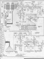
POWER SUPPLY (ALL MODELS)
The power supply uses a 5U4 rectifier tube with a conventional filter circuit.
TUBE SOCKET VOLTAGES
Voltages shown on the schematics are taken with a 20,000 ohm-per-volt meter.
Line variations may cause up to 20% variation in the indicated voltages.
To make tube sockets accessible, remove lever from shaft of expression unit on
amplifier; loosen cable clamp on lower shelf; remove four amplifier mounting
screws and turn amplifier upside down, being careful not to rest on expression
unit lever.
The tabs and expression lever may be in any position, and no key
should be depressed unless specified,
REVERBERATION AMPLIFIER (M-lOO)
When either "Reverberation I," "Reverberation II," or both are used, the music
played will be reverberated.
This reverberation signal is in addition to the
normal sound produced through the two 12" speakers connected to the main ampli^
f ier
A separate amplifier and speaker are incorporated in the instrument for
this purpose,
•
A signal from the voice coil terminals of the regular speakers in the console
goes through a resistor network and two Incandescent lamps to the drive coils
of the reverberation unit, as shown under "input to reverberation unit" in the
s chema tic d ia g ram
17
The incandescent lamps are used as volume limlters or volume
compression circuit.
When the organ is played loudly, the lamp filaments become hot and
Increase in resistance, and, therefore, the amount of signal furnished
to Che
reverberation unit does not increase as fast as the volume of the no-reverberated signal.
This is a desirable musical effect, since a greater proportion
of reverberated signal is needed at low volume levels.
The drive coils introduce vibration in two coil springs.
These vibrations
bounce hack and forth in the coils springs to simulate natural echoes of sound,
in a large room.
Pickup coils at the other end of the two springs drive the
input of the amplifier.
The amplifier output drives an 8 ohm 8" speaker.
SPECIAL EaUIPMENT
RADIO. PHONOGRAPH. OR MICROPHONE
A phonograph, radio, or microphone amplifier will play through
the organ speaker if connected to the pin jack marked "RADIO-PHONO" located
on the expression
control unit of the organ amplifier.
The device should have an output level
of about 1/2 volt maximum, and must have its own volume
control, as neither the
expression pedal nor the "Volume" tablet will affect it. The organ may
be played at the same time.
In the Model M only, occasionally for special effects it may be
desirable to
apply vibrato to the signal from a phonograph, radio or microphone.
In this
case connect to the pin jack market "SPEC-INPUT".
This point has a low impedance to ground (about 7000 ohms) and may conveniently be driven from
the voice
coll terminals of an amplifier having a level of about 5 volts maximum.
The
expression pedal, "volume" tablet, and three vibrato tablets will
then be effective on the input signal just as they are on the organ music.
EXTENSION SPEAKER
An additional speaker, of the permanent magnet dynamic type, may be
attached
to the organ if special circumstances make it desirable.
It should be connected to the two voice coil terminals on the amplifier.
It is essential that
the speaker be at least 10" in diameter and be mounted in
an adequate baffle
to bring out the organ pedal notes properly.
The console speaker voice coil
wires may be left connected or not, as desired.
Hammond Organ tone cabinets may be used as extension speakers.
ing the necessary connections can be secured from your dealer.
A kit for mak-
EAR PHONE (MONAURAL)
Ear phones may be connected to the organ if someone wishes to
practice without
disturbing others.
They will generally give adequate volume when connected to
the^ voice coil" terminals of the amplifier, with the
speaker disconnected. A
resistor of 6 to ID ohms, with power rating not less than 10 watts must
be connected across these terminals whenever the speaker is disconnected.
18
EAR PHONE (STEREO)
Stereo ear phones can give pleasing results when attached as shown in the schmatic below. A separate two pole double throw switch is required in addition to
the listed resistors and jack.
Use of good quality ear phones made by David
Clark, Koss, or Telex are recommended and can be secured from any parts supply
house.
GN.
T^J
100 -a
Organ Spk, wires
BLK,
CN,
©-
£:-3
Rev, Spk. wires
BLK-
10
jo.
10 W
*
SPECIAL POWER SOURCES
The organ must always be connected to an alternating current source of the
voltage and frequency specified on the name plate.
If the only available power
source is direct current or has a frequency different from that specified, it
will be necessary to provide a converter or motor generator of at least 170
watts capacity.
PRACTICAL SERVICE SUGGESTIONS
ORGAN DOES NOT PLAY
(a)
If the starting motor does not operate when the "Start" switch is pressed
and If the tubes do not light with the'^Run'' switch on, check the power
wiring, power switch, line cord, line cord plug, and wall outlet.
(b)
If the generator turns and the tubes light, but no sound can be obtained
with all controls in playing position, the most likely source of trouble
is the amplifier.
In most respects this is a conventional amplifier
circuit, and the schematic diagrams will enable the service man to lo-
cate the trouble.
ONE KEY DOES NOT PLAY OR A HARMONIC IS MISSING
(Tests to be made with "Drawbars" tab depressed)
This may mean a dirty key contact, a broken connection, or a dead note in the
generator. The steps below will serve to isolate the trouble(a)
Ordinarily only one of the several frequencies used on the key will be
missing.
This can be determined by holding the key and operating each
drawbar for that manual, observing on which drawbar the key falls to play
Reference to the manual wiring chart, figure 18 will tell which frequency
number is missing.
(b)
See whether the same frequency is missing where it is used on other keys
of the same manual.
The wiring chart will tell with what other key and
19
(c)
(d)
(e)
(f)
what other drawbar you should get the same frequency. If It is missing
In some
on one key but not on others, a key contact is probably dirty.
cases it may be cleared by striking the key 15 or 20 times in a rapid
If this procedure is not effective,
staccato manner to loosen the dirt.
(See
adjustment of the busbar shifter for that manual will clear it,
"manuals" section on a prior page for location and manner of adjustment).
This will slide the busbars endwise so they present a clean contact surface.
In extreme cases, it may be necessary to hold down the faulty key
while making the adjustment,
If the frequency is missing on all keys of one manual but not on the other
manual, look for a break in the cable connecting one manual to the other.
If the frequency is missing on both manuals, check the manual-to-generator
cable or the generator itself.
The output of any signal frequency on the tone generator may be checked
by pulling out any drawbar and connecting a clip lead from the back end
of the drawbar to the generator terminal in question.
See Figures 14,
If the generator
15, and 16 for location of all generator terminals.
Is all right, the note will play loudly.
CAUTION;
Never test the tone generator with an outside source of current
such as a continuity meter, as serious damage may result to the sensitive
filter transformers and permanent magnets.
By the above method, all
necessary tests of the tone generator may be made with the current sup^
plied by the generator itself.
If it fails to play, try touching the clip to the input side of the filter
coil (not the grounded tap) and the input side of the filter condenser
(Figures 14, 15 and 16) in order to check these parts.
Disconnect the
If
condenser to eliminate the possibility of a grounded transformer
the signal is still missing at the magnet coil terminal, it means that
the tone wheel is not turnings the coil is defective, or the magnet is
.
(g)
(h)
(i)
not properly adjusted.
If the tone wheel is not turning^ the frequency of the other wheel on
the same shaft will also be missing (with the exception of a few wheels
which are alone). On the generator magnet location drawing (Figure 13),
the two frequencies whose numbers are connected by a dotted line are on
the same shaft.
Antoher way to check the wheel is to raise the generator
slightly and feel the wheel with your finger to see if it is turning. Each
wheel is located directly behind its magnet, shown in Figure 13.
If the magnet coil is defective, the generator must be returned to the
factory, as replacement of a coil necessitates dismantling the entire
generator,
It is possible, although unlikely, that the magnet may have become loose
It may
and moved so far from the wheel as to make the not inaudible.
be adjusted as described in the following paragraph.
ONE NOTE IS WEAK
(a)
Trace the note as described in the preceding section to see whether
weakness is due to dirty contact, poor connection, defective filter or
reduced output of magnet coil. Check at each point by comparing intensities with higher and lower frequency numbers.
(b)
It is possible that one or more notes may be acoustically weak, due to the
room and the furnishing, although the actual signal level is equal to that
of adjacent notes.
This can be checked by reading voltages of the various
notes on an output meter connected to the voice coil terminals on the amplifier.
All notes will not give equal output, but voltage should vary smoothly
In this test variations of less than 30% should be ignored
from note to note.
20
,
(c)
Each magnet is set at the factory by tapping it gently, with the set screw
partially loosened, while observing an output meter. Experience has shown
that the magnets seldon need adjustment and that setting them without
proper equipment involves danger of damaging both magnet and wheel.
Therefore, it is not recommended that the service man attempt this adjustment.
PERCUSSION NOTES WEAKt DO NOT PLAYi OR DO NOT DECAY PROPERLY
(a)
Adjust percussion cutoff control; with expression pedal wide open,
"Volume Soft" tab up, upper "Drawbars" tab down, all drawbars pushed in,
press "Third Harmonic" and "Fast Decay" tabs. Hold down first C key on
upper manual and adjust percussion cutoff control to the exact point of
cutoff or silence,
(b)
Check tubes V7, V8, V9(c)
Always adjust percussion cutoff control after replacing V9 C12AU7).
PEDAL NOTE SOUNDS AT FULL VOLUME (WHEN PEDAL IS NOT BEING PLAYED)
It is possible to make a black pedal lock down and play continuously by
(a)
striking it very hard at an angle so that it moves sidewise as well as
downward.
This will never occur if the pedals are used properly, as
only slight pressure with the toe is required for playing.
(b)
A pedal locked down in this way will remain visibly depressed and tilted.
It can be released by pressing it down very hard, with a slight pressure
opposite to the direction of tilt.
No permanent damage will result.
PEDAL NOTE
(a)
(b)
(c)
(d)
SOUNDS FAINTLY (WHEN ORGAN IS NOT BEING PLAYED)
In this case the pedal cutoff control may be adjusted as follows:
Set expression pedal wide open, pull pedal drawbar to its loudest position,
and leave three pedal tabs up.
Play highest pedal key and then release it. Wait at least 15 seconds for
pedal note to die away.
Slowly turn pedal cutoff adjustment (on face of amplifier) clockwise
until pedal note just disappears.
Do not turn it any farther.
Always recheck this adjustment when replacing the 6BA6 tube.
HUM
(a)
(b)
(c)
(d)
A loud 60 cycle or 120 cycle hum in the speaker may come from some nearby electrical appliance, as explained on the instruction card.
It may be
picked up by the matching transformer, the vibrato line, or the console
wiring.
Hum from this source will disappear if you ground the signal
input terminals on the amplifier to the chassis.
It may be eliminated by
moving either the console or the appliance.
The faint pedal note heard when the pedal cutoff adjustment needs setting
may sometimes be mistaken for hum.
Check it as described under "Pedal
note sounds faintly when organ is not being played.
Any other hum must originate in the amplifier circuit, and can generally
be cured by replacing one or more of the electrolytic condensers.
In case hum originates in the amplifier but is not due to the electrolytic
condensers, its source can be isolated by successively removing tubes or
by grounding successive points in the signal circuit
21
-
REPLACING TUBES
(a)
The vacuum tubes are all standard radio types and can be tested in the
usual way.
(b)
If the 6BA6 tube is replaced, check the pedal cutoff adjustment as explained under "Pedal note sounds faintly when organ is not being played",
If tube V9 is replaced, check percussion cutoff adjustment as explained
(c)
under "Percussion notes weak, do not play, or do not decay properly".
PROCEDURE FOR REMOVING PARTS IN NEED OF REPAIR OR REPLACEMENT
TO REMOVE KEY FROM UPPER MANUAL (Mi M-2i M-3)
(a)
Remove music rack by unscrewing thumb screw, unhooking brace, and lifting
it from console.
(b)
Remove music rack base by taking out two screws in upper manual end blocks,
(c)
Remove metal angle fastened across keyboard by two screws
(d)
To remove a black key loosen its key mounting screw (See Figure 3), unhook
key from screw and lift out key.
(e)
To remove a white key loosen its key mounting screw and those of adjacent
black keys. Unhook these keys from screws, push them back, and lift out
white key,
M-lOO
(a)
(b)
(c)
(d)
(e)
(f)
Remove music panel and top.
Remove four screws which secure metal cover on control panel assembly,
Remove two large screws located at ends of control assembly, which secure
It to upper manual.
Pull out drawbar on extreme left and fold control assembly back,
To remove a black key, loosen its key mounting screw (See Figure 7), unhook key from screw and lift out key.
To remove a white key, loosen its key mounting screw and those of adjacent
black keys. Unhook these keys from screws, push them back, and lift out
white key.
TO REMOVE A KEY FROM LOWER MANUAL (Mi M-2i M'3)
(a)
Remove music rack by unscrewing thumb screw, unhooking brace, and lifting
it from console.
Remove music rack base by taking out two screws in upper manual end blocks(b)
(c)
Detach pedal volume control (Figure 3) by removing two machine screws, loosening wood screw which holds friction clip to top of console, and unhooking from
drawbar.
Remove upper manual mounting bolts "A" and "B" under keyboard (Figure 33)
(d)
(e)
Place a 3/4" board under each upper manual chassis mounting block; this will
hold up upper manual sufficiently to make lower manual key mounting screws
accessible,
(f)
To remove a black key loosen its key mounting screw (See Figure 3), unhook
key from screw and lift out key.
To remove a white key loosen its key mounting screw and those of adjacent
(g)
black keys. Unhook these keys from screws, push them back, and lift out
white key,
M-lOO
(a)
(b)
(c)
(d)
Remove music panel and top
Remove generator dust cover by taking out seven screws from edge of generator shelf and loosening four screws in cover just below upper manual assembly
Remove upper manual mounting bolts (2) which are located at ends of console
directly above front corners of generator.
Remove two screws which pass through angle brackets into upper manual.
22
.
-
(e)
(f)
(g)
(h)
.
,
mounted on inside of cheek blocks. These screws are accessible from
front of organ.
Tilt manual from front, being careful that It does not slip back.
Using 1/4" box ratchet, loosen key mounting screw,
To remove a black key, loosen its key mounting screw (see Figure 7), unhook key from screw and lift out key.
To remove a white key loosen its key mounting screw and those of adjacent
black keys. Unhook these keys from screws, push them back, and lift out
white key.
TO REMOVE A DRAWBAR CONTACT SPRING (Mj M-2i M-3)
Push drawbar all the way in(a)
(b)
Remove screw and nut at back end of drawbar (Figure 3).
(c)
Pull out contact spring while pressing with thumb to release pressure on
contact.
To disconnect spring entirely, unsolder wire.
Do not under any circumstances pull drawbar forward while contact spring
(d)
is off, as damper spring will catch in slot and ne'cessitate removal of
entire drawbar assembly
M-lOO
(a)
(b)
(c)
(d)
Remove music panel and top.
Remove four screws which secure metal cover on control panel assembly,
Pull out contact spring while pressing with thumb to release pressure on
contact.
To disconnect spring entirely, unsolder wire.
Do not under any circumstances pull drawbar forward while contact spring
is off, as damper spring will catch in slot and necessitate removal of
entire drawbar assembly.
TO REMOVE A DRAWBAR OR DRAWBAR KNOB (Mi M-2i M-3)
(a)
Remove music rack by unscrewing thumb screw, unhooking brace, and lifting it from console,
(b)
Remove music rack base by taking out two screws in upper manual end blocks
(c)
Remove 8 hexagonal head machine screws holding drawbar assembly and one
screw fastening angle across upper manual keys
(d)
To remove knob pull drawbar assembly toward front of console (be careful not to scratch control panel surface)
prop it up, and remove screw
which holds knob
(e)
To remove drawbar and contact spring, pull them out at back of assembly,
while pressing with thumb to release pressure on contact.
(f)
To separate drawbar from contact spring remove screw and nut at back end
of drawbar.
M-lOO
,
,
(a)
(b)
(c)
(d)
(e)
Remove music panel and top.
Remove four screws which secure metal cover on control panel assembly.
Remove two large screws located at ends of control assembly which secure
It to upper manual (Pull out drawbar on extreme left) and fold back.
Remove 4 hexagonal head machine screws holding drawbar assembly,
To remove knob, pull drawbar assembly toward front of console (be careful not to scratch control panel surface)
prop it up, and remove screw
which holds knob.
To remove drawbar and contact spring, pull them out at back of assembly,
while pressing with thumb to release pressure on contact,
To separate drawbar from contact spring remove screw and nut at back end
of drawbar
,
(f)
(g)
23
.
,
,
,
TO REMOVE UPPER MANUAL (Mi M-2i M-3)
Remove music rack by unscrewing thumb screw, unhooking brace, and lifting
(a)
it from console
Remove music rack base by taking out two screws in upper manual end blocks.
(b)
(c)
Remove dust cover over generator by taking our seven screws from edge of
generator shelf and loosening four screws in cover just below upper manual
assembly
(d)
Detach control panel by removing 6 machine screws from top of panel, and lay
panel on generator, being careful not to damage generator wiring.
Control
panel wires need not be disconnected.
(e)
Detach pedal volume control (Figure 3) by removing two screws which hold it
and loosening wood screw which holds friction clip to top of console; unhook
control from drawbar and lay it on generator, being careful not to damage
generator wiring. Volume control wires need not be disconnected,
(f)
Remove two screws fastening matching transformer bracket to upper manual,
take off round cover held by two screws, unsolder and detach shielded wires
and black wire from transformer,
Re-attach matching transformer to upper manual.
Cg)
(h)
Unsolder wires from lower manual drawbars.
(i)
Remove upper manual mounting bolts "A" and "B" under keyboard (Figure 33).
Remove the two upper manual stop plates, held by two wood screws (Figure 3).
(j )
Prop up front of upper manual so that its terminal strip is accessible.
(k)
Be
careful when raising and lowering manual that its terminal strip is not damaged by rubbing lower manual keys
Unsolder manual cable from terminal strip. Lower manual into normal position,
(1)
Detach vibrato line box by removing two screws in sides of box fastening it
(m)
to underside of console top; lay line box on top of generator, being careful
not to damage wiring on generator.
Line box wires need not be unsoldered
(early M-3 only)
(n)
Where line box is of metal construction unsolder wires from scanner leaving
it attached to manual.
(o)
Carefully lift manual assembly (including drawbars and matching transformer)
out through back of console,
Remove metal angle fastened across keyboard by two screws.
(p)
Take out 8 hexagonal head machine screws from drawbar assembly and carefully
(q)
lift off drawbar assembly and matching transformer assembly.
-
M-lOO
(a)
(b)
(c)
(d)
(e)
Remove music panel and top,
Remove four screws which secure metal cover on control panel assembly.
Remove two large screws located at ends of control assembly which secure
it to upper manual.
Remove generator dust cover by taking out seven screws from edge of generator shelf and loosening four screws in cover just below manual assembly,
Remove two manual ho Id- down bolts located at ends of console directly above
front generator corners
Reinstall dust cover temporarily,
Remove two screws fastening matching transformer bracket to upper manual,
Detach pedal volume control by removing two screws which hold it to manual
assembly. Unhook control from drawbar and lay it on generator cover.
Volume control wires need not be disconnected
Remove vibrato line box by taking out four screws attaching it to rear of
upper manual.
Remove screws holding four plastic clamps containing wiring.
-
(f)
(g)
"
(h)
(i)
24
, .
Cj )
(k)
(1)
(m)
(n)
Co)
(p)
(q)
Locate nine coded wires coming from busbars inside manual, Tehse are
found at right rear of manual.
Trace this troup of wires to upper manual
preset tabs and unsolder. Note location and routing as shown on wiring
diagram and in consoleTake out four hex head machine screws from drawbar assembly.
Entire control panel, drawbar assembly, line box, pedal volume control
and matching transformer can now rest on generator cover.
Reinsert two bolts which held the control assembly to the manual assembly,
Remove two screws which pass through angle brackets into upper manual.
Prop up front of upper manual so that its terminal strip is accessible.
Be careful when raising and lowering manual that its terminal strip is
not damaged by rubbing lower manual keysUnsolder manual cable from terminal strip. Lower manual into normal
positionCarefully lift manual assembly out of console.
t
TO REMOVE LOWER MANUAL (Mi M'2» M-3)
(a)
Remove music rack by unscrewing thumb screw, unhooking brace, and lifting
it from console.
(b)
Remove music rack base by taking out two screws in upper manual end blocks.
(c)
Remove dust cover over generator by taking out seven screws from edge of
generator shelf and loosening four screws in cover just below upper manual
assembly.
(d)
Loosen wood screw holding friction clip of pedal volume control (Figure
3) to top of console,
Remove upper manual mounting bolts "A" and "B" under keyboard. (Figure 33)
Ce)
(f)
Prop up front of upper manual as far as possible.
Be careful when raising
and lowering upper manual that its terminal strip is not damaged by rugging
lower manual keys.
Remove two hexagonal head mounting bolts from rear end of lower manual
(g)
chassis mounting blocks.
(h)
Remove three screws X, Y, Z under keyboard (Figure 33).
(i)
Remove lower manual end blocks by taking out screws C, D, E, and F under
keyboard (Figure 33)
Unsolder manual cable wires from terminal strip,
(j)
(k)
Lift manual out through front of console, being careful not to damage
woodwork.
(g)
M'lOO
Remove screws holding four plastic clamps containing wires, on rear of
upper manual.
Locate nine coded wires coming from busbars inside of lower manual- These
are found at right rear of manual. Trace this group of wires to lower
manual preset tabs and unsolder. Note location and routing as shown on
wiring diagram and in console.
Prop upper manual from front, being careful it does not slip back.
Remove both lower manual end blocks, by removing two screws through manual frame and one screw through bracket in check block.
Remove lower manual terminal cover, hedl by four screws under keyboard.
Remove two hex bolts which secure lower manual to case.
Loosen (don't r^tnove) four hex screws holding front of lower manual to
(h)
front rail of case.
Lif t out lower manual
(a)
(b)
(c)
(d)
(e)
(f)
25
.
,
.
.
.
TO DETACH AND OPEN CONTROL PANEL (Mi M-2» M-3)
(a)
Remove dust cover over generator by taking out seven screws from edge of
generator shelf and loosening four screws in cover just below upper manual assemblyControl tablet box may now
(b)
Remove six machine screws from top of panel.
be lowered and pulled toward rear of console.
Lay box upside down on generator (being careful not to damage wiring on
(c)
Care should
generator) and remove bottom cover by taking out four screws.
be taken not to pull the wires or cables excessively during this procedure.
None of the wires or cables need be disconnected.
OPEN PERCUSSION CONTROL SWITCH (M-3 ONLY)
Remove screws C and D under keyboard (Figure 33)
Remove four fastenings holding panel to wood block.
Turn tablet assembly upside down and remove bottom cover by taking out
two screws
Wires need not be disconnected
TO DETACH
(a)
(b)
(c)
A^a3
.
TO REMOVE GENERATOR <Mt M-2» M-3j M-IOO) FIRST PULL OUT LINE PLUG
(a)
Remove dust cover over generator by taking out seven screws from edge
of generator shelf and loosening four screws in cover just below upper
manual assembly,
(b)
Unsolder, at line panel, six wires (5 wires on M, M-2, M-3) to running
and starting switches
(c)
Unsolder, at line panel, three wires to amplifier,
Unsolder pedal and manual cables from generator,
(d)
(e)
Disconnect scanner shielded wire from amplifier terminal.
(f)
Unsolder cable of six green wires from scanner terminals.
Unsolder scanner wires from terminals 3, 4, and 5 (12, 13, and 14 on M,
(g)
M^2, M-3) on vibrato line box.
(h)
Unsolder two black wires from generator cover near start motor end,
and also grey wire (connected to junction of two carbon resistors on
generator cover)
(i)
Remove 4 generator hold down screws (4 cotter pins from clamping screws
and remove screws on M and M-2).
Unhook four suspension springs from generator.
(j )
(k)
Carefully lift out generator.
TO REMOVE STARTING MOTOR (Mt M-2> M-3i M-lOO) FIRST PULL OUT LINE PLUG
Remove dust cover over generator by taking out seven screws from edge
(a)
of generator shelf and loosening four screws in cover just below upper
manual assembly.
Remove oiling threads (tied to two motor bearings) from oil trough by
(b)
pulling or cutting them, (When replacing threads be sure they go under
(c)
(d)
(e)
felt in trough)
Provide more slack in lead wires at starting motor by pulling wires
carefully,
Unscrew two hexagonal studs extending beyond outer edge of motor.
Lift motor out and unsolder its lead wires- (Be careful to remove and
replace all threads).
TO REPLACE PILOT LIGHT (M-lOO ONLY)
(a)
Remove music panel and top.
(b)
Remove four screws which secure metal cover on control panel assembly.
Lift fiber shield over bulb and replace bulb.
(c)
NOTE;
Use No. 12GE 6.3V
.ISA
Minature
26
2
pin.
,
TO REPLACE A BROKEN TAB CM- 100 ONLY)
Remove music panel and top,
(a)
Remove four screws which secure metal cover on control panel assembly,
(b)
Remove two Phillips screws from front of control panel that hold bank
(c)
of switcht^s associated with tab to be replaced.
Remove lock washer from either end of switch assembly, and pull rod out
(d)
It may be necessary to tilt assembly so
so it just clears broken tabthat free end of rod will clear adjacent switch assembly,
Remove remains of broken tab and insert new piece,
(e)
A small bronze spring washer will be found between tab and one
NOTE;
Be sure this is reinserted with new tab.
side of switch assembly.
TO REMOVE VIBRATO LINE BOX (Mt M-2i M-3t M-IQO)
Unsolder wires from line box terminals
(a)
Remove two screws in bottom edge of box fastening it to underside of
(b)
On later units, remove four screws fastening it to rear
console topof upper manual.
TO REMOVE PEDAL KEYBOARD (M, M-2i-M-3i M-lOO)
Remove dust cover over generator by taking out seven screws from edge
(a)
of generator shelf and loosening four screws in cover just below upper
manual assemblyUnsolder pedal cable from generator.
(b)
Remove three pedal keyboard twisted wires from amplifier terminal panel,
(c)
Place suitable wooden strips under pedal keyboard assembly to support
(d)
First remove two screws in back of console
it when screws are removed.
(Figure 3), and then remove three screws on lower shelf toward front of
console over pedal keyboard.
It may be necessary to remove two speakers to take out these
NOTE:
(e)
latter mentioned screws.
(When re-installing pedLift console and pull out keyboard and stripsal keyboard replace two screws in back of console first, leaving these
screws loose until remaining screws are replaced),
TO REMOVE EXPRESSION PEDAL (M, M-2» M-3- M-lOO)
Disconnect two twisted wires from "SUS SW" terminals on amplifier, (Model
(a)
M, M-2) terminals "W" and "X'' on M-3)
Prop up right end of console at least 6 inches from floor.
(b)
Unhook coil spring from expression unit arm.
(c)
Remove screw linking expression unit on amplifier to expression pedal.
(d)
.
NOTE FOR M-3 ONLY
A change in all amplfiier coded ''H'' and above removes the positive voltage from
This can be incorporated in earlier amplifiers
the stators of the swell assemblyThe end result will place a block-condenser (,02mfdby following the steps below.
This change will insure con^
600V) between pin 1 of the 12AX7 and the swell statorstinued noise free operation of earlier amplifiers.
SEE FIGURE 36A OF SERVICE ^L\NUAL
Remove jumper,
STEP #1 - Move lower lead of C16 from lug B to lug A,
STEP t/2 - Move lower leads of R33, R35, C16 and green lead from lug C
to lug BRTEP //3 - Move lower lead of R32, Cl5 and blue lead (C15 from ug D to lug
- Add C9 from lug C to D.
STEP
^
H
26A
C)
DETACHABLE
MUSIC RACK
DRAWBARS
LOWER
MANUAL
UPPER on
SWELL MANUAL
CONTROL
TABLETS
Expression
(volume) pecal
FRONT VIEW OF CONSOLE-MODEL M ORGAN
FIGURE 1
DIMENSIONS:
AC INPUT:
OUTPUT:
WEIGhfT:
45-5/8" wide; 25-3/8" DEEP; 42"HIGH
103 WATTS
11 WATTS E^I.A.
249 LBS,
27
DRAWBARS
LOWER
MANUAL
UPPER
PEDAL
MANUAL
MIDDLE
UPPER OR
DETACHABLE
MUSIC RACK
SOLO MANUAL
CONTROL
TABLETS
EXPRESSION
(VOLUME) PECAL
FRONT VIEW OF CONSOLE
-
MODEL
N4-2
ORGAN
FIGURE 2
DIMENSIONS:
AC mPUT:
OUTPUT:
WEIGHT:
45-5/8" wide; 25-3/8" DEEP! 42" HIGH
103 WATTS
11 WATTS E.I. A.
249 LBS-
28
SYNCHRONOUS MOTOR
PEDAL VOLUME CONTROL
MUSIC RACK BRACE
DRAWBARS
MANUAL
MATCHING
STOP
PLATE
TRANSFORMER
VIBRATO
SCANNER
LINE
WNEL
STARTING
MOTOR
PEDAL
CABLE
GENERATOR
CLAMPING SCREWS
LINE
CORD
EXPRESSION
CONTROL UNIT
TONE
GENERATOR
PEDAL I^EYBOARO
MOUNTING SCREWS
es)
'BACK VIEW OF CONSOLE
-
(with dust cover removed)
FIGURE 3
29
MODEL
M-2
ORGAN
PEDAL DRAWBAR UPPER MAKUAL
DRAWBARS
LOWER MANUAL
DRAWBARS
LOWER OR
GREAT MANUAL
UPPER OR
SOLO MANUAL
CONTROL
TABLETS
PERCUSSION
CONTROL
TABLETS
"START" AND
RLJN" SWITCHES
(UNDER MANUAJ-)
PEDAL
SUSTAINING
CONTROL
FIGURE
1
FRONT VIEW OF CONSOLE
hA'3
FIGURE 4
DIMENSIONS^
AC INPUT:
OUTPUT:
VEIGHT:
45-5/8" WIDE? 25-3/8"DEEP; 42" HIGH
103 WATTS
11 WATTS E.I. A.
249 LBS.
30
VIBRATO LINE
BOX
MATCHfNG
TRANSFORWEft
SCANNER
RUN MOTOh
KEt BUS 3 AH
SHIFTERS
STARTING
POWER
Terminal
PANEL
MOTOR
AMPLlFfER
GENERATOR
PEDAL SWfTCh
ENCLOSED)
PHOr^OGRAPM
INPUT
PEDAL GUT OFF
CONTROL
SWELL CONTROL
PERCUSSION CUT OFF
CONTROL
BACK VIEW OF CONSOLE
(WITH DUST COVER REMOVED)
FIGURE 5
31
M-^
PEDAL DRAWBAR
LOWER MANUAL
DRAWBARS
CONTROL
TABLETS
START & RUN
SWITCHES
PILOT LIGHT
UPPER OR
SOLO MANUAL
LOWER OR
GREAT MANUAL
PEDAL
KEYBOARD
EXPRESSION
(VOLUME) PEDAL
TYPICAL M-lOO SERIES INSTRUMENT
DIMENSIONS: 44-3/4" WIDE; 25-1/2" DEEP; 44-1/2" HIGH
155 WATTS
AC INPUT:
OUTPUT:
WEIGHT:
22
WATTS
2 68
E.
I.
A.
LBS.
FIGURE 6
32
TAB SWITCH ASSEMBLY
PEDAL CONTROL
MATCHING TRANSFORMER
VIBRATO LINE BOX
START
MOTOR
SCANNER
RUN MOTOR
SUSPENSION
SPRING
GENERATOR
POWER
TERMINAL
PANEL
AMPLIFIER
REVERBERATION
UNIT AND
AMPLIFIER
PHONO
INPUT
SWELL CONTROL
PEDAL
CUTOFF
CONTROL
PERCUSSION
CUT OFF
CONTROL
M-lOO
BACK VIEW OF CONSOLE
GENERATOR DUST COVER REMOVED
FIGURE 7
33
SPGIIAL
IMPUT'
UPPER
WAAJUAL
1
0FMWBAA5
MATCHING
TRA^4S-
FORMER
LOWER
P4ANUAL
AMOUNT
MANUAL
SECTION
OF
OF
VIBRATO
VIBAATO'
LINE
INTER-
VIBRATO
SCAhNCR
TABLET
AMPLlFfER
MEDIATE
SECTION OF
EXPRES50N
CONTROL
AMPLriEfl
ORAWVBAftS
I
ourmrr
VlftRATO
g
SEC TON
RADIO-
CHORUS'
TABLET
PHONO
.*>
OF
AMPLIFIER
5
u
o
VIBRATO
TABLET
SPEAKER
PEDAL SECTCN
OF
PEOALS
PEOAL
ORAWBAR
AMPLIFIER
PEDAL
cutoff'
PEDAL
PEDAJ.
PEOAL
ATTACK
TABLET
decay'
SUSTAIN IMC
TABLET
CONTROL
FIGURE 8
BLOCK DIAGRAM
-
VOLUME
TABLET
MODEL M ORGAN
RADIO
PKONO'
I
UPPER
WANUAL
LOWER
MAP4LIAL
DRAWBARS
DPAVvBHftHS
UPPER
MATCHING
VIBRATO
TRANS-
FORMER
MANUAL"
TABLET
LOWER
VIBRATO
SOLO
TRAhiS-
LOWER
manual'
FORMER
TABLET
MATCHING
VtBRATO'
CHANNEL
viflRATO
CHANNEL
INTERMEDIATE
section of
amplif;€R
VIBRATO
LINE
X
VIBRATO
cHonus"
TABLET
PEDALS
EKPRE^^iO*^
T
OUTPUT
CONTROL
SECTION Of
AMPLIFIER
AMOUNT OF
VIBRATO
VlSRATO"
TABLET
SCANNER
SPEAKER
PEPC'J55rOt4
I
OM-OF
F
ECTOR
:>Cl
TABLET
TABLET
-—{ DECAV TflOtET
PERCU^S'ON
= ECTIONt OF
AMPLIFIER
«ADlO
PMQNO'
^OHJME TABLET
1
I
UPPER"
wA-CwiNG
VIBRATO
THflNS-
man.^al'
FOavER
TABLET
MO
50L0
ViBPATO'
CHANNEL
VIBHATO
LOAER
MATCMfMG
DRAWBARS
T H
AM 5
vlSF^ATG
U A^JUAl'
TASLET
-
FORMED
MtDJATE
SECTJON O*
AMPLif JER
n
VhSRATO
CHANNEL
LINE
EXPRE^^IQPJ
CONTROL
AMOUNT OF
VI
an AT 0"
TABLET
Output
section of
awpuifier
SPEAKER
vipflATO
5CANNEH
O
3
VIBRATO
CHORDS"
TA&LET
U <
O
PEDAL SECTION
PECAU
OF
DRAi^flAP
AHPHFIER
I
PEOA?^
pf:oal
'
P£ DAL
PEDAL
CUTOFF'
AT tack"
DECAT
SUSTAINING
ADJU5Tl,»ENT
TABLET
TABLET
CONTROL
FIGURE 10 BLOCK DIAGRAM MODEL M-3
Vast
i
C^A^^AAS
Tft&t
EVUv*ftA8^ -Afl
LOWfTt
H
*
3
^CAL^
^VStT TAW
FLUTES '
]—
cavVaa
JPEttCy5^k»4
TAU
ViM/^n^
Of
4H*ft-*^
^OTT TA4
vQlumc
TABLET
OUTPUT TERMINAL
COIL
MAGNET
TOME WHEEL
ONE Slot Of COIL CBOUNOED
COIL
FIGURE 12
-TYPICAL TONE GENERATOR
@ @ @ @
e
\@ \0
^^
® ® ®
\
18
\
\
\
(5^\
^
57
so;
\@
\
(24)
^
\
\
(60)
\
'Q
'
\
\
\
\
^
\
(SB)
®^@ ® ®
e
«
e
® ©
(7^
\
\
(56
D
13)
\
BACK or GENERATOR
(AT BACK OF COMSOCE)
SYh*CHftOkOOS
MOTOR CMD
STARTING
MOTOR EM)
*NOT PRESENT ON Mi M-2t M-3
SYNCHRONOUS
MOTOR END
STARTING
FRONT OF GENERATOR
MOTOR END
@ Q @
@
e
36}
(65)
\
\
©\ @\ @\
\
@\ @\ ®\ ©\
S^
40
(31
^
DOTTED LINES SHOW FREQUENCIES WHOSE TOME WHEELS ARE ON SAME ShiAfT
FIGURE 13
-
MAGNET LOCATIONS
36
-
ON TONE GENERATOR
A^
riLTni TnjLMVDfitocni
95 We 6 ^
ri''Ci>
C04KP4CM
iTUITiHC
7|\47\64Vs8';69\*5\02\fl6' S7\9l\72\4e\«5\a9\^^
42"^«« ^SVUo-*^
,^76 ^ 54^-363
;;
59^y 6 ;
"ii'>^>^ «2^««3-^'
«-*
52 2^,
6.
^^
572V* ^ 50 ;^^79
-
^'3fl'^4V^
^^
«^V°3V*>i^^'V2"3/'*
"^^^^2^29^^ 5 ^22^ io^^V^ I ^' 20**^fl ^SV^
*^'
""^
I
NUMBERS ON FILTER TRANSFORMERS ARE FREQUENCY NUMBERS OF TRANSFORMERS
NUMBERS BELOW TRANSFORMERS ARE OUTPUT TERMINAL FREQUENCY NUMBERS
FIGURE
14-
GENERATOR COVER MOOEL M ORGAN
-
fl42-|
FILTER TnAl4V0RMCII»
MOTOA (t«
j
T^e
^£3'*^
n
Ul
STARTTHC
UDTOfl END
^ !gB^4
NUMBERS ON FILTER TRANSFORMERS ARE FREQUENCY NUMBERS OF TRANSFORMERS
NUMBERS ABOVE AND BELOW TRANSFORMERS ARE OUTPUT TERMINAL FREQUENCY NUMBERS
FIGURE GA- GENERATOR COVER- MODEL M
HR'AL
f*\jVlALn raOftS *PVC -JP
FIGURE 14A
37
ORGAN
—
o
o
z
O O
o o
m m
r r
5 >
> f"
''
Z
z c
m
Tl
o
> > rn
> S
»
rp
O o
—
'
3
m
I/)
It
2
.
<^^
en
m
-4
O
P7
2
W
>
o
O
o
CO
W
B
CO
c c
LOWER MANUAL -
r
UPPER MANUAL
DRAWBAR ASSEMBLY
FIGURE 19
KEYING
PEDAL
CONTACT
FOR ALL
PEDALS
CONTACT
SPRINGS
PEDAL
CABLE
PEDAL
TENSION
SPRINGS
NOTE OF
SCALE
GENERATOR
FREQUENCY
NUMBER
PEDAL KEYBOARD - MODEL
FIGURE 20
42
M. M-2t AND M-3
PEDAL
CONTACT
KEYING CONTACT
FOR ALL
PEDALS
SPRINGS
PEDAL
CABLE
PEDAL
TENStON
SPRINGS
NOTE OF
SCALE
8
8
FIGURE
21
9
10
n
12
PEDAL KEY BOARD
,
13
GENERATOR
FREQUENCY
NUMBER
MODEL M-lOO
OUTPUT
TO aJT
TUBE
AMOUNT OF VIBRATO TABLET
IWUT FAOM
ej5 TUBE
H
SECTIONS or VtBRATO LIME
veAATO
CMOflUS'
TABLET
VIBRATO
TABLET
FIGURE 22 'FUNDAMENTAL OiAGRAW OF VIBRATO
SYSTEM
IN
MODEL M ORGAN
43
OUTPUT OF
h^^Rh#^AL
A TO lin£
boh.
viaPATO
SYSTEM
.000^7
^
Tl22Xi5 ^^*
VTT"^Ol
20 L2I
U1
O
O
D
w
"I
VIBRATO
RI4
RI5
I2>^EJS
"vibrato
chorus"
Vl&RATO
PHASE SHIFT L^NE
-
X
"OFF-
FIGURE 23 -VIBRATO SYSTEM
MODEL
VIBRATO-
M CONSOLES BEH^W
StRlftL
NtjM&ER li509
r40RM4L
INPLJT OF
VlRRATO
5V&TEM
FIGURE 24-V^BRATO SYSTEM
NORMAL VibRATO
VI&RATO"
'ON"
MODtL
>A
CQKjSOLES
44
SERIAL NUMBER ii509 f^MD AftO^E
-
O
O
o
_
.
o
o
OUTPUT TO
INTERMEDIATE
AMPLIFIER
AMOUNT OF VIBRATO TABLET
INPUT FROM
MANUAL
AMPLIFIER
SECTIONS OF VIBRATO LINE
VIBRATO
CHOftUS"
TABLET
FIGURE 25
-FUNDAMENTAL DIAGRAM OF VIBRATO
SYSTEM IN MODEL M-2 AND M-3
45
OUTPUT TO
INTERMEDIATE
AMPLIFIER
AMOUWT OF VIBRATO TABLET
I
INPUT FROM
MANUAL
AMPLIFIER
SECTIONS OF VIBRATO LINE
VIBRATO
CHORUS'
CELESTE I
TAB
TABS
fcELESTE
MODEL M-lOO
FUNDAMENTAL DIAGRAM OF VIBRATO SYSTEM
FIGURE 26
m
LI3
UA
H
L2
Lio
LI6
FIGURE 27
LI7
U20
Lai
-VIBRATO LINE BOX-MODEL M AND M-2 ORGAN
46
LI
L-1
Mf Gt
Later models use a somewhat smaller box, with metal framework.
FIGURE 28
FIGURE 29
VIBRATO LINE BOX
VIBRATO LINE BOX
ROTOR CONTACT
T"™'""'
'
MODEL M-3
^^^^^ ^-100
PiN
ROTOR 'NSULATOR
END BRUSH MOUNTED
ON LEAF SPRING
-2 SIDE BRUSHES
ROTOR PLATES
STATIONARY PLATES
SIDE
BRUSH
TENSION SPRING
^
A-BRUSH COVER REMOVED TO SHOW BRUSHES
B-VlEW WITH SCANNER COVER REMOVED
(2 SETS OF PLATES REMOVED TO SHOW ROTOR
FIGURE 30 vjgRATO
47
SCANNER
OUTPUT O*
ST STEM
INPUT O*
VlflHATQ
^5000
vkaoATo t .ne box
J
VIBRATO Ph>5E SHIFT LINE
fl^a
'¥lBft*TO
I
=
VIBRATO SYSTEM
(rfODE L W' 1 CONSOLES Stfli*L NijWBEfl
iMOO TO 2S25i)
FIGURE 31
OLfTFHjT OF
VIBRATO
STSTEM
hWP JT
OF
VIMATO
SrSTtM
*TD LINE BtMt
NOflMAL
Vlftft*TO'
VIBRATO SYSTEM
UOOEL M-Z CON&OLCa SERIAU
fiuhiDta
FIGURE 32
48
2S2S4 AND ABOVE
THIS VIBRATO LINE BOX
HAS DIFFERENT APPEARANCE THAN UNIT IN
FIGURE 31
—
LOWER MANUAL SCREWS
CONSOLE
LEG
END BLOCK SCREWS
i
HOLE fOft
ACCESS TO
LOWER MANUAL TERMINAL STRJR COVER
(S
UPPER MANUAL MOUNTING BOLTS
SCREWS HOLDING MANUALS
(VIEW LOOKING UP UNDER KEYBOARD)
FIGURE 33
NOTES
49
SCREW
50
A
^Ti^V
N35a:j
i
11
<
o
LU
Q
O
O
a
Jl
O
1/1
U-
a
9
z
o
-J
<
^ovraTT
z
o
r
3
o
in
u
O
z
z
o
o
s
LlJ
z
g
LLi
J,
Q
<
in
I
u
m
UJ
cr
CD
N33tio ei
*W)-T-13A'a3tf CJ.
o-
imgici
A3U? ti
J
3
o
p
Ij-
o
rt
t—
z
<
ir
m O
Z Q
UJ
51
^
^
n
CI
m
UJ
?2
So
<
m —
u.
?
m
c
o
IP
^>
O
O
O
V
>
z
>
o
m
<
I
NOTE:
amplifiers coded "H" and above removes che positive voltage from che stacors
of rhe swell assembly. This can be incorporated in earlier amplifiers by following the steps below. The end result will place a blocking condenser (.02 mfd, 600v) between pin 1 of the 12AX7
and the swell stacors. This change will insure continued noise free operation of earlier amplifiers.
A change
in all
Step tfl
Step Ul
Step *3
Step UA
Move lower lead of C17 from lug B to lug A. Remove jumper.
Move lower leads of R33, R35» C16 and Green lead from lug C co lug B
Move lower lead of R32, C15 and Blue lead (C15) from lug D co lug C.
Add C9 from lug C to D,
r
=^s^
:_i
"
^
^^^^-^
^
s
PICTORIAL M-3 AMP (PARTIAL)
r
FIGURE 36A
53
54
CO
W
W
en
o
o
I
a;
-I
n, to
O
m
o
o
O m
U
o
I/)
m
Ui
I
55
i
u w w w w tj
>>>>>>>
o o ooooo
ti]
CQ CQ CQ CQ CQ CQ CQ
Q Q Q Q Q Q Q
u^
f\j
r-
o X CO
ro
^
O
^ CO ^
o
-^ -^
^
iTf
in
CO Lr»
in fo in f\j
-^ no
ro
^
O '^ vD vO ^
iTi
tn
^^
f\]
ld
fvj
rn -H CO
O O O ^ ^
vD
^
*i
J
_
-»
4
on
I
<1>
m
UJ
:0
O
=s
AAA/^
>
n
r
o
P
or
i
o
o
r
<
c/>
f¥
\^ rv
*
m
>
rs
o
B ^ g
& rn m
o
ra
^
FN)
5 s -^
cz o ^
m — n
cr
4
3
C3P
— ?
trt
?^
5 5
O
2
»--
o
o
TTTTTaTB
i3T^
?
£?l
-I
p e
w
en
ih
si
/\
i'
2
58
V
5
H
MANUAL
UPPER MA.^^JAL
DRAW9ARS
LOWER MANUAL
DRAWBAR
MATCH
W
BUSBARS IN
0RAW3AR
6. a
MEG C6
.000015
C35
^l
J— ^^d7nQO
.005
R27
.000015
I
}*-
^SCANNER^
?
5CAN
R29
SMEG;LdMEO
CIS C40
V4
feSC7
,0002 .0002
PEO"
4__^^
25V &
?j:i^
-±
S
Rd
,4-VW.—
P5\2.£MEG
1
KEY CONTACT
I
I
RESISTANCE
WIRES ALL
J6
EACH DRAWBAR
HAS 2 BRUSHES
OHMS
CONNECTED BY
ONE OHW RESJSTOR
TAPPED 1/2 OHM RESISTOR
PROVIDES ^NTEN3tTY
STEPS FOR DRAWBARS
INPUT'
d:
u
5^-LU
^<SET
OF NINE CONTACTS Ur^DER
TYPICAL PLAYING KEY ON
i>^A*jv-o
—
—
c-AVAr<i
r"
LOWER MANUAL
BUSBARS
V
NORMAL J--/--/--/-"
<h
UPPER MANUAL
AMOUNT OF
NEGATIVE FEEDBACJ^
CIRCUIT PROVIDES VOLUME
COMPENSATION FOR
'VIBRATO OFF"
J|_l
C36
at
<
.25
SPEC
yiBRATO LiNE BOX^
TERMINALS
SMALL
R25
—VA*
MEG
1-5
AMPLIFIER
C44
CONTROL
LOUD
_Y
lOV.
TRAN' R4
Tl
NINE
EXPRESSION
22 MEG
MATCHING
OUTPU
AMPLIFIER
--vv.v
TRANSFORMER
'
INTERMEDIATE
AMPLIFIER
300V.
VIBRATO LINE BOX
TO CONTROL PANEL
TO SCANNER
D
rr^
-z
%
z2:cijc^« %^
-i
A-
MATCHING
BK
CO
^
TRANSFORMER
Bh
/-
DRAWBAR
V
TO VIBRATO
TO AMPLIFIER
LINE •\
VIBRATO LINE BOX
NUMBERS
i
52
74
29 ze
51
MANUAL
rs
fB^
BUSBARS
<U
GY
\
6
V
HI
FREOUF^*CY
6
6
75
74
6
NUMBERS -
11^'_
6 o 6
cooooc
6 6
Qcoboo
J=dt..
t*.Uo
i
c 6
CT'jiX'^^^ygj:?,'
MANUAL
29
TO GENERATOR
\
TO CONTROL PANEL
R42
GENERATOR
JUMPER WIRES
CONNECT SCANNER
B5
TERMINALS OF
^\ SAME NUMBERS
c
669 WJo
AZ9 309
7i o
47
640 SBc
3S9
15o 62g BOc £7c
69£^
339
3&9
o
43;
72o 4&v 65
BOO 41
Sf p
3Ji;.
89o 70c 46
S4c
o87
i39
06B d44 cCl
^tr?
I
2
^ BOTTO M
P*-
L.
"
•T
/
.
/f^
^^A
BK
I
J-^
-7
/
76
-^3 WIRES TO
BN BK ^' VIBRATO LINE BOX
54 ^83
6^ 23
la
59 ^ 76
52
M^ 28
4T 21
1
ftf
*!
57
30
9] 26
2,
IQ
.
79
55 ^
7^^
24
^
VIBRATO
SCANNER
jv-'Vif'vwjrjj^
FROM
CONTROL PANEL
'START-
'RUNSWITCH
BUTTON
FROM
CONTROL PANEL
^d—b^^ r1
'
I
1
AN
"
£J
AC LINE
120V MOV
BRWN
GREY BLK
WH
GY
BK
YEL
BK i5
iBN BL
1
LINE
PANEL
YEL
^
lA'
eCN WPRES TO
CONTROL PANEL
GY
,
BK
BK
ISN
SPKR
FIELD
77
12^
20
_53
sT
c49^ FREQUENCY NUMBERS
o
25
C CN WIRES TO
SCANNER
l_OWER
DQor
BK Wtf*ES TO
VIBRATO LfNt
e
'
BK
,11
4 BN WIRES TO
VIBRATO LJNE
.GN
^ FROM MANUAL
Upr^ER
r^
TO CONTROL
PANEL
CONTROL PANEL
TO MATCH. TRANS
G a
Rt
TO AMPLIFIER
PEDAL
75
C
DRAWBARS
X 3 '^~n ^TO amplifier
IIOO^OCCf.CCOCODOo'-'
H^
D
t^
11
—
B
VIBRATO LINE BOX
^
Z<:22:tx<:c^
TO CONTROL Panel
^
.
P-T
[T'Z
TO SCANNER
-^^--»-"»^w_^^
^"V
»;
^fafT") ,T0
DRAWBARS
AMPLIFIER
MATCHING
TRANSFORMER
HK
^Trj 1^
OJ
TO AMPLIFIER— ^^*4
PEDAL
DRAWBAR
rni
r.
~^
13
74
FREQUENCY
hJUMBERS
6
—
>/'.'
ii>
4BN WfFES TO
VIBRATO LINE
29 29
5'
O
MANUAL
16
FROM MANUAL
BUSBARS
\
BK WIRES TO
VIBRATO LINE
fl
^
GY
BN
'.
PANEL
-TOAMPLJF"IER
UPPER
7"
—
'
1^
000
OS
6 6 a 6
Tl'
7^"'"
"7
Q
^
"T
T-
c
660
60
00
t b
3060
f>
29 2&
\A
^
EEC^CSS^
LOWER
MANUAL
6GN WIRES TO
SCANNER
\^h
6K
u
U
y
74
75
^^ctctt:^:':':^^'^':'^^^'^^?^
GENERATOR
CN WfPES TO
CONTROL PANEL
e
GENERATOR
o
^
\
%
?
CONNECT SCANNER'
TERMINALS OF
SAME NUMBERS
42? 309
359 **Oo
:>
90T
BN BK
i
"
'START-
SWITCH
BUTTON
^
o
3a';*
eg? ^45?
02?
59
.
e/"
ii
4
„^^ 34p 390
o
1
o
~
70
a
8i^
n
3 6c
CI
72; ^af
i
'es'^
0'
3
'
4fl^
r--,
l^3i
BN L
n
P iif ^ f
T
I
TrTT--"=cxrj'!^?3&^':^^
V RA^XJlTV.A^Tl
eSi
|44
BK
SI
till
13
6
5534 BO,77_53
.32
53 ^75
5i
.30
^*<EQUfcf^CT
NUMBERS
i.
50 .73
rt'-Ajj.AJTi
FROM
CONTROL PANEL
^
1?__!
FROM CONTROL PANEL
(PEDAL DRAWBAR}
FROM
DECAY SUS
FIELD
SW
BKl
BN
LINE
PANEL
BKi
m
IN
GN
GN
\^
;B N[BL
SW
PEDAL
VOICE
COIL
PED
KEY
BNI
VI
6K
GY
V
BKjBK
III3
MATCH TRANS.
5PKR
BK
BN
COLOR CODE
SPEAKER
FROM PEDAL
DRAWBAR
>
WH
BM
^
VIBRATO LINE BOX
AC LINE
I2CV nov
BRWN
GREY BLK
YEL
S7
fl3
1
I
YEL
ae^
50^79
FROM
CONTROL PAN£;L
i
31
11'^
T
W
52
76
i
43?
-i^TO CONTROL PANEL
R42-
SCANNER
tr.-^tJjr.T^J
run'
ae-
339
LLXJii!
-tr.
63
a
c
64^
47?
71
BOTTOM
VIBRATO
CONTROL
TO MATCH. TRANS
V
rr'^TT'^
-TO
CONTROL PANEL
AMPLIFIER
Y
BK
GY
fBN
SCAN
PED
BK
WBK
6
WATCH
TRAN
GN
/
r
AMPLIFIER
MANIUAL
LOWER WAf^UAL
0*TCMlHG
t
„
BagaR
Q?eBRE^59?
OOOOiO IN SERifciMO ^b49& ANO AbOVt
C20
INTERMEDIATE
Off
TZ
MA**UAL
CiO
GENERATORS
'vibrato !i:"H^
49-91 OSE
THtS DRCUlT
LOWER
.000025
r
t
I
I
«E5i5T*NCt
lb
OKU2
0.2
Ohm RESI5TOH
I
VJB
THIS CiPCUJT
S^-^
ZU)
1-1*0
CHAhSELS
U
VI
47000
M
!
B
K -f •
4
+Z90
2.7H£<i
k4£&
"^
VJSE
tTh
>
^ELttTED
FACTORS TO
R2A
R2
^ BRUSHES
ONNECTCD Bv
«2»0 I'^uEgJ LAUEG
r^
eALA»dC(.
^\t
2tlV
KtT CWJTaCT
(iENtaATORS
A4-4B
*
«-.
•'^2*0
m
DR*WB*n
i-4=
g>oy
\- SOFT
^°'
.0DC2
R2«
ON'
^
*5
€5NT^^^^ C2S
6SC7
CIS
uanual.'
jO
,0OOD24-,000C§O
V4
'4-^.
I^mLG
AMPLIFIER
(5tT AT *ACTO«>')
EXPRE35*0N
CONTROLT
RiV
O
OUTPUT
AMPLfFlER
'vibrato
THA^SFOHMfP,
IS
cJ
o
V3
-OOI
t5J7|z5v I,
(T-^-^ti
T
t
*Z90
ff^
£60 V
1^
'AMOUNT OF VIBRATO'
•ri
ipW
^
itj
or s.
*
SCANNER
lu
U^
NihiE
^
viB
LINE-
LOWER MANUAL BULBARS
VIBWA70 L^Ng
(V
>
A
4
-^SM,
CONTACT! UNCER
TTPJ C*L Plating f^EY OH
IJPP£H U*NUAL
^
\
*Z40
5tT or
>.
--LI
fC).
Y^
BO*
TERMINALS
16-43 uit
THIS CIRCUIT
»/i
'vibrato
^JNOHMAl
CMOnuS'
\ VIBRATCT
h^
'
< p
> o
ru
SET Of NINE CONTACT! UNDER
rTf*iC*L Slaving utT ON
fO«^
^\
EIACT
SEE rifcURE
LOWER UAhUAL
\1MS1
VIBRATO
NEH*TOW OUTrUT^
TERMINALS
vlMATO
CtRCUlT
IS
PHASE SHIFT LINE
NORMAL
VOLUME
NO PEDAL PRESSED
NO PEEAL PRESSED 260V
ANY PECAL PRESSED S5V
OV.
AMY PEDAL PRESSED v
(
PEDAL^^MPLlFiER /
^
^Z
Ai^L
"SOFT'
PEDAL PRESSED 45V
AM" PEDAL PHESSeO 55V
N«]
iVlTH
20000-OHMS-PER-VOlT METER
££ MEIf
^
"^
^05
^
-M 4s 4^
POWER
TRANSFORMER
T4
RUM SWITCH
POWER SUPPLY
120 V
ZiO
f>i
DC VOLTAGES MEASURED
fc.1V
HEATERS
o<
110
V
tZVO
PEDAL CABlE
BLA
RB?
-START-
STNCHBO-
STARTING
MOTOR
?5o
WJTTOH (looo FOR
tslOUS
MOTOR
a4Dv)
'-^EYSw-
Pes
.
R74
-Zi
4700
GREY
^DCCAT Sw'gj'suS
^ORual'
PEDAL
"PEDAL
ATTACK'
'OFF
ON
FAST
DELAY"
pedal contacts
SCHEMATIC DIAGRAM
MODEL M-2 ~ 19000 AND ABOVE
FIGURE 42
62
EMRRtSSrON COhYWOl
V)
PEDAL
Sustaining
0©00@0@0
TOP VltW OF AMPLIFIER
NUUBEn
DAGRAM- MODEL M-2
lUOO
AND ABOVI
COUPLES VIBRATO line; SCRIAL WU»UR nz»4 ANDAbOvE
RM
^»ooo
-z\
—
T4
CONTACT OPENS
SERIAL
3iiW
SPEAKER
PEDAL HErlN&
CONTACT C^.OiES
AFTER ANY PEDAL
SCHEMATIC
E^8
"^S 3,.
Ra««
T3
CONTROL
ff*gg*a*^b
HEATER RESISTOR
(iBDDOFORiAO
Sw"
-
^ «
39 MEG
ATT- KEY
od"e
'^AVv
-t-ZftO
f
—
lELO
^fcrr^
70O
*
OHMSB
EARLY M-; CONSOLES (seRlAL ntfS. &ELOW iljso)
RBS IS S4000. Ra7 (1 jOpOO. Af*D SPEAKER FIELD IS
lOo! OHMS.
\H
I
5
VIBRATO LINE BOX
TO COMTROl
PAi^EL
TO SCAHWE-R
TO GENERATOR
WIHE5 TO
COhTPOL PANFL
6
G^J
STARTING
SYNC.
MOTOR
MOTOR
SERIAL NO .9000
AND ABOVE
WiRtNG DIAGRAM OF
HAMMOND ORGAN CONSOLE MODEL M-2
WIRING DIAGRAM
MODEL H-2 - I90OO AND ABOVE
FIGURE 43
63
DRAWBARS
VIBRATO
TO CONTROL
LINE
PANEL
BOX
GV
MATCHING TRANSFORMERS
GY
T2(lDWER
M^NiJAt.)
Tl(SOLO manual)
TO SCANNER
TO QEHIHAJOR
6 GN WIRES TO
CONTROL PANEL
STARTING
5YNC.
MOTOR
MOTOR
WIRING DIAGRAM
MODEL M-2 - 25254 AND ABOVE
FIGURE 43A
64
WiRlMG DIAGRAM OF
HAMMOND ORGAN CONSOLE MODEL M-2
I
COUPLED VIBRATO LINE SERIAI. 25254 AND ABOVE
—
R 30
/
H
30LO
T
SOLD
RRRH
iMATCHING
Fl
LJLJLJLJL^
C6 MANUAL
AMPLIFIER
-WW
- VlB*UTO -^
ORAw6AaS
,0000.^0
n22
ft2<
MATCHi^JG
TOAMSfORiv
10
MEG
OUTPUT AMPLIFIER
INTERMEDIATE AMPLIFIER
CI3 iroooos
cz
EXPRESSION
5 3WF:G
c^O |jOQQO^Q
COMT^OL
ogog:?^ -
/LOLjD
0000^7,
^
LOW£P
^ SOFT
CI6
CIS
«^a
majjllal"
GENERATORS
V 3B
2AU7
C^i
r4o;
KTOOc!
VIBRATO
^
C25A
5ET At TACTCRV
ooaogo
^-24
.001
R4^A
305 V
.2'
OJ
MEG
N-l
i/
OOQ2 5
R3Z
4^'^L 1J5E
THjS C<RCU(T
6
*l-5
VIBRATO
/
CHAf^MEL
£50
SELECTED AT
TACTORV TO
.
.0OO2 2
^MEf^
o
BAQIO
s-;g
-+250
l^
fti^ort
.^^-^
u
H6
U
PHO« O
BALANCE
CHANNELS
^7ME&
INRJT
1
^^-l-
*.
00O03O
^
^^90
v4a;
=-
^^s
3
SPEA-^EA VOICE
COIL e Ohms
ul
^?M£G
R7
"fl
lOWEG
VIBPaTO CHANNEL
7MeG
VI
R5
te
INJPUT
2
/Od
C^.
—r/zu-r—V-^A
6AU6
t-VjVw
n3fl<5 .56 v^:.
V3A
0047
CSI aND qj£ ARE OWlTTCD
I2AU7
m]
VA TEflvllSiAL6(5 ABOUT 'OC vol ^
i^lgA 15 47MELJ *ND <3 CONNECTED PE"wCErj
IfciiMirJAufi AMD Ci-OUND ify CODE A£ fl ONlt,
I
GENERATORS
R5^A
'1,6
Q
MWE
5ET OP
CGMTACT3
r^t^
-
CQUJACT
;*-l7
RESISTANCE
WIRES ALL
IS
AMPLIFIER
PERCU55
KEY
"urJOEH T^'OiCAL T^LAYIPSG
,j
047
PEPCU'SSION
^OFF'
maraeo code
VOLUME
PERCUSS lON
20OVT6
A"'
OP VJBRATQ
5^i^.AL.
y 4700O
C34
SELECTOR'
Third-
W
\-
"f^.ODl
'
• 205-^
^o5
1
"On'
^JOTE A^P'.LFiERS w;th no
LETTE=J a:^E COCE A.
"T
HAPMOMLC
I
C:^E.i:
zgo
4hH
PERCUSSION
s
1*4
C Oncf.
PEDAL SIGNAL
MEG
ui
Rid
Tt
.
1
i5
>
rJ
.^C2B
QMMS
<Xi
1
OMlTlt^
V4-
OMLV
'139f3?r^iJ CHMe.)j5 CONNECTED &ETa£?.^ V4TEP,WiNAl
5v QlAS^ i« CODE
3 iWC CC-JUNDj AiuD USED INMEADC"
RIO
b-
c27 used only \n
Amplifiers code
f and above.
3CSV
-SECC^JD^
Sr-1ALL
rfl
I
I
o
T
RSe*!**
H
"^
?oov5
vg
[^7000
ViSRATO LINE
J2AU7
SELECTED AT FACTORY TO
SOJf TEt^tMIKALS
&AL*NCE CHANNELS
on
'per C 'J SSI ON
GENERATORS
i/i
®
K'^
nee
^.7M£G
;6-43 USE
TH15 CIRCUIT
LZ
COT OFF"
-r-'VWv
<
fy
<JR5'*
1.
o
r:53
<
IT
UJ
Q-O
^—'AVv
-=-
MEG
SI
'i'EPCUSSlON decay"
25 V
—\wv4700
PERCUSSION
VOLLJMe-
3
lJ
o
f^oaMAL
^^UOOO
PHA5E 5HIFT LINE
-VIBRATO
^
o
PEDAL AMPLJ F^ER
z
o
PEO*L
vio
ENEHATQP OUTPUT
6BAfi
TERMINALS
POWER SUPPLY
OF^Av^eAa
C59^^o^
lEATER
J^
PESiSTOfl
-z
NO PED^L PRESSED OV
ANY PEDAL PRESSED
W
I
T7
6 0V
HEATERS
TC H
—0
t
3J0
JV
R30
'
PEO-L
M
5
TART
250
iWlTCK
CUTOFF
= EDAL
1
RUN
S
STARTING
SYNCHRO-
MOTOR
MOTOR
NOUS
CaSlE
R62
377
4700
Z:
S
"J
^
380 V
JUMPER f
T5
I
W6
NORMAL
PCOAL
PEOAL
DECAT
CD
DȣF F*GO*AA"a
PEDAL SIGNAL CONTACT OF LA^T
REOAL RRE5SED REMAINS OPEN
^
U^ED ONLY
IN
AMPLIF'.ER^
CODE &
flS;D
.i^ PEDAL rtEVfAlG
CONTACT CLOSES
AFTER ANY PEDAL
CONTACT 0PEV5
AB-T'VG
22A
X
ti
* « VALU6
EXPf^ESSJON
T7
CONTROL
'off
®
FA5r
ATTACft
PEDAL SUSTAINING
6O0O
150
2200
C63
^^%oo
©
/^
,r
j.^^
.
r-'
ALL DC VOLTAGES WEASLRED WITH ZO.CDO
OHMS-PER-VOLF VIETER^ ANO ALL CONTROL
TAGLETS TILTING TOWa^C ^RONT OP C0N5OL
SPEAKER
Plug
-tOOV
TiTTTOMMS
700
RlDI
Rioa
PI
03
.V^AV-
390OQ
-60O
lOOOO
-19
T6
© ©©
TOP vjew of amplifier
CONTROL
SCHEMA^C
SEH lAL
IN CCLIE 4
zcoo
Field
.
V6
j-\
'^gc'
SPEAKER
IN
r/>
RIGC
^m
CY
'ZZ
^
*^^oo
S.9Me G 2 5 MEG
IZMEG
R97
^.
waeov
C6I
.00220^
R96
-o-
'WW—
Ji:
TRAP4SfORMEH
4SO0 (JQOOO FOR Z34VJ
NO PEDAL ^HISSED 290V
ANY PEOAL PHE55EO lOOV
;-
POWE^
AMPLlFi^K'
DIAGRAM
MODEL M-3
NUM&ER J©aX3 AND AfeOVE
#*« USEi ONLY
IN C"L. h A Ahfl-^LlFlt Vti
SCHEMATIC DIAGRAM
MODEL M-3
FIGURE 44
65
—
on
MANUALS
ijpOfP
/
DRAWBARS.
—y ^-•
I
IMATCHING
iTRANSrc'^MER
—
I
OBfflS
RSI
-^
.
.
OUTPUT AMPLIFIER
iNTElRMEDiATE AMPLlFlE^R
^
CI3
R2P.
JVSV„
"on
wATiHtMG
1
.
i7MEG
SOLO.
MAMUAL
2
10OO3C'
P20"
"viBWaTO-D'
LOWER MANLfAL
r—
—
J
J/
OODOH
EXPRESSION
CO^JTROL
/LOVO
lOMEG. .\3MEG
CIO
ON
VtEPATO
4*^%,^_-4—\w.
iL_ J^^^l47MfG
-^-w^-r
470od
fACTORV
CZ3i;*'5ETAT
^-^
t
CgPnQOOCg Q
0O0D24
^t
CZI
'2Ai7 r4DV
LOWER
CI5
r
CI6
wanual"
GENETS A TCR5
-
I
5£:lECTED at
NON VIBRATO
CHANNEL
FACTORV TO
INPUT
.27
MEG
_[_
^^
.27 MEG
op
HADIO
PHON O
290
^
PJ
u
.
+290
-—WA—
MEG
T3
"O
o
5tOV
(tROM V4A)
o fr^2
u
.OG002C
,—^^v^
305V
6V6
"^^
BALANCE
CHANNELS
i>Ol
,V6
O0022 ^002 E
t+3?
R32
A/i^-'
VvW
SMEG
6 MEG
O
49-91 USE
THIS CIRCUIT
'^*230
I
00D090
V^5
R4G
I
-
25A
SPEA
COIL e OHMS
in
2?MEG
—
"OMEG t^MEG
AflA/^
VlSR'^TC' rlHANJNEL
C3'/00l
rVW*-
R5
&Aue
I^JPlJT
V3A
0047
VI
AMF^HFL^R CCDE G ANC ABOV £
i£AU7
I
CODE
H ANjD A feOVEl
-
-
3C5v
Ol/T^P JT
ACE:'ED
C.3
G£tJEPATQR5
A4,4B USE
THIS IlRCUiT ,^
DjIC-^^
PtlDAL
SET or M^JE COT^TACTS
UNDER TYPICAL PLAYING KEY
=0!
P^RCUSSiON AMPLIFIER
CC^JTACT
RE5t5TANCE
KEEV
R47
r^W^
WIRES ALL
ffi
I&
SjGKIAL
VOLUME
C26
4 7 MEG
0KM5
T4
v9
v7
R^
T5
2ftU7
AMOUNT
PEBCUS&ION
bl&NAL
'
^00vT6
or VIBRATO
PERCUSSiOhi
d>
PERCUSSION SELECTOR"
'OFF'
!
"ON"
'THIRD"
^047
H4
o
I
-SECOND"
SMALL
200\H
^
rt
+
'
V9
I3AU7
ViG^aTO LIME
BOX TEfiroli^ALS
J
SELECTED A"^ FACTCRV TO
&ALANCE CHANNELS
/
*32
-f
4#
JO
PERCUSS'
GEt^ERATORS
ie-43 lse
R60
CUT
R59
^
-VAV
4.7WtG
THIS CiRCLIIT
R55
R57
25 V
—WVv4700
L3
LJ
E47
L3
01
i\i
»-<^
l.Sf^CG
13
.VA:-,-VVvVA-
RN^AL
PERCUSSION DEC*Y
M
62000
l*Ena;5SioN
/5LOW
EAST
VOLUMEnj
R5D
-=
NORMAL
i32
^
:^^1200C
id
PHA5£ iHIFT
-VIBRATO
^
i_lME
o
PEDAL AMPL nC-R
I
IERATOP OUTPUT
c^EDAL
C56
e9A6
TERMINALS
POWER SUPPLY
DRAW&AR
VIO
01
iJ+-
^'^^.>^. ('^^5E:j}
D91 RE5:6TOR
powe:^
4500 fiSOOO FOR Z54V)
-
1
R93
NO PEDAL PRESSED 290V
c
PREr^ED OV
ANY PEDAL PRESSED (V
R95
-A'AV-
SOOO
50
^
Bl
'START'
PEDAL
5w;tch
Cutoff
R90
250
STARTING
MOTOR
SYNCHRO
NOUS
MOTOR
C6
VAV
O—4700
S
Rei
-VV/v-
^^^-^l
^°/. DO
3
3gMEG ^^MEG
T3
y6
I
f
!T4
EXPRESSJON
T7
CONTROL
©©O
PEDAL
ATTACK""^'
CCDD'EF F-GCAA'B
PEDAL SrGT^AL CONTACT OF LA^T
PEOAL PRESSED REMAINS OPtN
SCHEMATIC DIAGRAM
MODEL M-3 - 904-85 Aid ABOVE
FIGURE 44A
CLO&Eb 1/VMEN AWV PEDA.L
IE ri^L^^ED (AFT F.R.
PECAL SicUAL OCMTACT
OPEN^)AfcJO CPCN^ WHEN
PEDAL 15 RfcLeA^ED
SPEAKER
FIELD
SUSTAI.-^ING
TCP VIEW OF AM^LJFiER
CONTROL
SCHEMATIC
DIAGRAM
MODEL M-3
W
T^:^H
r
!T6
PEDAL
450
JUMPER''
TS
PEDAL
DECAY
PCDAL I\EVIH& CONTACT
^^.0022
-lOOV
Tc57
V6
C62
-L
L ^v
GV
'-2 2
^VvV
©*--'
—WA60OO
^.'400
.000 FOR
PEOAL CABLE
^"^7
C&l
RiOO
"2200
A
380V
%
i^PEAh^ER
ALL DC VOLTAGES MEASURED WITH ?aOOO
OHh/S'PER-^OLT METEP AND ALL CONTROL
TABLETS TiLTfNG TOWARD FRONT OF COWSOlL
Q+^90
^3Z
R56
PE1>^L
R65
300OO
66
T7
t.OV
HE ATERS
ANV PEDAL PRESSED lOOV
NO
t20^
_ transformed
310
P-UG
niTrm700
RiOl
i90OO
'2 2
-0=
OHMS
RiOE
'AVvt
R105
leoo
-19
V:25
—
^
"OFP;
UPPea MANUAL5
r'
DRAWBARS
T\
"VIBRATO
LOWER MA>JLrAL
DRAWBARS
TRANSFORMER
d
TjKj
SOLO
>S
MANUAL'
"Of
MATCHlWG
IMATCHING
I
R20
^7MEG
lOMEG
-^
VUviE':*
LOWER
3
A^v^
CONTROL
,2
,.0000 27
7
MEG
l-WV^J
fl)
0002? D0Q2Z
R32
R33
-WW
ISMECX
(FROM
CHAt4NEL
iA
MANUAL
BULBARS
MAMTJAL
SELECTED
FACTORY
_
*l 5
NQN VIBRATO
LOWfR
R23
.27MEG
VAj
INPUT
^
47
30SV
f
MEG
I
^'2-
Ti^
>fo
q:<
Ti:
1
BALANCE
Channels
RAOIO "
p f^Or4 o
T3
2<^
-
I.BMEG
M
6V6 "
J
CZ7.
ui
'255
krt
"0-19
Of
o
U>
[ti?G*l
"^
J44^
c:
*3zo
SPEA^-Efl vOfCE
^
COIL S OHMS
'ev6
'
R7
Rfl
lOMEG 2 7 MEG
RS
C4
VI
00-17
AMPLIFIER CODE
T^P OMfTTED.
fiALie
CDO^
CODE
I47G0'
GENERATORS
CIRCUIT
2V1E5
2
VI6RATO C*^ANNEL
iNPyT
i^
TTHIS
R40
BUSBARS
o-'AW
44^46 U5E
o\
oTgr
c?o
Lrt
CZ(
J2A)«7 W3s^
V6
THIS CIRCUIT
UPPER
V4&
A SOFT
Cl6
C5
lETAT FACTORY
000024 -OOO 090
C?0] /OOOOZO
/LOUO
c^5
<o
'
MAHVML
47viFf^
4TO'
EXPRESSION
I2AX7^,
CIO
P2B
VIBRATO
G£^CRAT0R5
V4A
ON
e
^^
OQl
-V/vV^/A^v---
RA^iS^GRMER
Output amplifier
intermediate: amplifier
AMPLiriER
M
J
3CSV
AND ABOUE - OO'^^UT
irJD A60''E
CI ADDED
AWD AiiOi-e - P4 SPf,/><ER.
<i
-
si*
^
O
(FROM
SET OF NINE COh^TACTS
UNDER TYPICAL ^LAYI hiG KEY
PERCUSSION AMPLIFIER
CO^JTACT
RESISTANCE
Pl^DAL
SlGWAL
*265
i^EY
R47
WIRES ALL
15
47 MEG
OHMS
c2a
K
PEi^CUSSlON
R46
C
c
HARMONIC
PERCUSSION
"OFF
AMOUNT
I7
2AU7
15
PERCUSSION
s
VOLUME
O—
OJ^
VIBRATO
9
C34
SELECTOR"
,001
"THJRD'
R46
SCANNER
M4
4
V
2a
MEG
t
t
'ON'
"SECONO"
Inorwil
SMALL
v9
U
s
"^n
p^
H
ViSP^ATO LINE
lEAtn
SELfTCTED *T FACTORY TO
BALAf4CE CHANNELS
TERMINALS
aOJf
\
.-^
-31
L
-H
'pERCuSSiGnT
CUT OFF" j
GENERATORS
R60
'VW^
4 7MEG
R59
l_V/,
I5WCG
ie-43 USE
THIS CifVCuiT
R33
t
—
P57
w\^
32000
25^
4700
PERCU5SIOM
l2
o
l3
lS
L(0
LI*
jus
LI4
LI2
1^
8
s
iriJ
8
iSSlON OECAY
M
^
^
g_
g_
J
8
^
CN
'\
i
^J
Si*
^_
u
VOLUME'
o
-=^
-^Wv
NOClMAL
>32
^^12000
^
VIBRATO PH A5E IM\V~ LINE
PEDAL AMPLI tier
C^
P^DAL
DRA*VBAR
eBA6
POWER SUPPLY
CS^.,01
PQWEO
'-^^E^)
RESISTOR
-—
__»,V.'.,
J50O CieOOQ FOR Zi4V)
o
R91
f'*"
(
]
T7
5 0V
HEATERS
^ECAL ^^RESSEb 2qOv
ANY PEDAL PRESS-ID lOOV
-235
I
9
^U4
MEG
0L
RQ5
g^ PEDAL
30000?^
^CUTOFF
1
STARTING
-START'
350
SWITCH 1000 FOR
:D^-=^
MOTOR
S^NCmRQNCU5
MOTOR
ff
R92
R96
'J}Q
60OO
C63
/"
320V
-J
C6iJ-
^'
Ft
ntoo
97
2300
ISO
=9^ 00
T:
'"Sioo
Ct2
-^.0022-
9-^*5
-^
*32
TRANSFORMER
NiO
.
—
*320
CbZA
4go
1
3201V.
'450
234V
'^
77
^/vWO—4700
S
—^A^^V-
eioi
^$?V-r^^-2 2
GV
3.9MEG ^2MEG
J_L2MEG
IfiO
Bi02
T3
v6
EXPRESSION
X i
CONTROL
NORMAL "OfF
ALL DC vClTACES MEASURED WITH 20.000
0HM5-PtR-yOL7 Mt'EP, ANO ALL CONTROL
TABLETS TJLTING TOAyiRD FRONT OF CONSOLl
-wv.
10 OOO
stooo
C64
-leo
25
I
I
PEDAL
FAS
ATTACK^
PEDAL
PLOAL hEYlNi-- L'^'lTACT OECAY
LLCf.ci. ^mEN any pedal
tC
IS Vr^..-^^. U AT
1
PEDAL Signal CONTACT OF LAST
PEOAL PRESSED REMAINS OPEN
\
T
,V5
ON'
PEDAL SUSTAIN
I
TO^ VIEW
rJG
(V5
^s;
OF AMPLlFtER
CONTROL
SCHEMATIC DIAGRAM
1
PF - _ S" -*JAl_ I.C^TACT
(-,N'ij) ASjn OPEN'-t
Wf^£N
PtOAL IS ftLLEASf O
(V6V
T
.
F-'-^
'iPtA''
F
-
'yt'\'\^\.
MODEL M-o
SCHEMATIC DI AGRAM
MODEL M-3 - 09466 AND ABOVE
FIGURE 44B
1
ri'i.
OS -If I
AN
u
A™
"'VI'-
67
1
!
DRAWBAR5
VIBRATO
BgaBBBegg
box
line:
MATCHING TRAM5rORMER5
g^ggBB^
b
TC SCA^m^R
TO COWTflOL CAMEL
FREQUENCY
NUMBERS
~
t GN WIHE^ TO
COWTROL
PA»Jt^
t:
% 5^^
^^
4
\
GENEiRATOR
CC^JNECT SCAKMER
TERMl'MAL^ or
TQ
O 54
??
85
£6
t.
90i
c
I
o
c
g
45
7
ezi
€2|
c
Be
67
E
73T
91
6*^
B«
<?
3^9
""3l"0
X C37
ZL
C
w
6^^ c.^^t 83
rHEQUENCY
p 1 5 TO
VIBRATO LJNE &CX
^3
I
16
^,S9
irl
VlBRATOE SCANNER
-,-^-"
ri :_
"^rr^^>V^'^>^^"^"^^Vi:
"VT^
.
^
*
26
1
4
c
^57
8J
9
2\
O
79 .55
o
o^o ^ 77 ^53
121
2^
5
c
fi*
24
2
--.-.vT.v-.:r^>j.-
^-
B*^
/^
WH v..
"start"
switch
switch
BK
rp^
N
_
_
_f^EAR
_
-yjly^
WJTH COVER
?E_*^OVEp;
^^-ite:
CO(_0« CODE
&N
orF
1
5PE*KPR PLUG riTS RECEPTACLE
OU AwPlIFiER
i
R
r^
I-
PEDAL
Cljtoff
TEL
0N
BN BL
Bk
GY
GY
^^—
LINE
PANEL
R90
TEL
i_ _^ J
O
BN
u
.
L
GN
V
W
X
YElRgn"":
|R
(J
r^iWJ r t_n
AM_PL_lFiER
|_ >
*
J
BK
BK
BM
Bl_
fBL)
(BL.)
TQ .Su STAtN 5VVITQ1.
*^Dn EKPRE^^fCfJ COhTftOL
w
10:
>t'jTTL
^^
BL^ef^ GH
-^ri
SYNC-
MOTOR
MOTOR
WIRING DIAGRAM
MODEL M-3
FIGURE 45
68
REFERENCE SYMBOL^ REFTR TQ SCHEMATIC
Diagram of o^^GAN mOD^L MO
WlRIMG DIAGRAM OF
HAMMOND ORGAN CONSOLE MODEL M-3
B«
BN
Black
«ED
OR
RED
ORArjGE
VEL
GN
YELLOW
GREEN
BL
BL'JE
v^O
VIOLET
GY
CEY
WH
WMITE
T
per:u5Sion'
CUTOrF
'
^1
BN
Jbl G^-JK
rREO.rJOS
rJ3TES
i£
|Bk_|sk_|BK_^!6K_^|BH_|Bk
11
10
9
fi
7
e
B
PEDAL KEYBOAPD
STARTING
^^
PERCJSSIC^J SWITCH
J
^^run"
IflN
\iRED
74 ^50
26
^
~^^
lL
i
„52
V^
1
c
1
^6
-3-
SN_,
4e
OTTOM
o
BL
^
5
^
€
d'
^
D
^*
C*
^
C
+
r
.
0PAWBAR5
S/ATCHING
VIBRATO
TO COMTPOL
_A__^OiZo
IS
fOCOl^TCO^, PAHtL-
rn^0
,
fiji
a
C
z
yf
o
jfijiFa
V
2
lO
OJ
V
n
OS O'
fffl
T2(lO*^EO manual.)
TO SCANNER
PAfJEL
A.
2
BOX
LINE
^
r
—
1
A.
r.
WH
3
i>
ro
pi*
75
TRANSFORMERS
^'cT^
Ti(solO liamuai.)
;
VI
O
-o
GV
TO AMPU^PliR
GN
^IQ
Pi^^^
gh
th:l
•-V
RED
VfH
rEL
/
^1
f^^.
PECj-.L
Cy
y
BK
DPAWBAP
:--"^'^v^'-^-'^-'-^.v='=---?--V-'---:^'^v^::^-^
M
>.v.v7j^:?.
r-^T^v'^ ^'n^g^:
'
TO SCnEOATOVV
?co:j<-:^5'
« Bn WIRES TO
Vitt'^TO LINE
r
SOLO
a o
5?
7S 7^
29
SI
25
VVAKiLiAL
le
'SCAMWfR
IMBEH5
BUSSARS
er
'f
^
g Qf^ WIRF3
TO SCAr^vjcB,
/
n
6'
sf
4?
i?--'
^-^EL
GN
9K
Clio
.14
'>'"VIC»
6oo
6 O & i O 6 6
FPECuEMCY
NUMBERS "
T5
O^OiOCooobooooOoCHi^
52
74
oCicioOoiibOo 0666
O'liicio
29
Si
LOWER
60600006001
1
^S
;^
M^frjLTAL
(B
i;x>'^
f
9
-'7"
.fl
V*.
L TD V16RATO
Ll^JE"
VlGRflT^ LJKJE
3
CONTROL PAMCL
CflEAP Vl^w
L
7
PAMEiJ
.^^-^
"^
JUMPER Wines
V
"= 0>jT<?0\^ PANEL-
H
*za
5^ME NUMSERS
c
iV
.
&I_ACK TO CO'yTPCU
Bft
^
^3^
fitB4
*
*
^
Al'^
aio 7z
A90
jM'
6C6
'890
700
^3'^
4fi
5TC
6&^
9
678
65<v
61&
5ai 659 67t 051 6e»
06
0^
oaa o*
^11
dST 674
oif
o^
CbBO
ozfc
679
oi
6S6
o<9
66-1
OfeO 077
o^
»
Oil
osi oaz
029 Q5
375
-^^^6
<^2i
Qio
OBO
6st
Qi7
03
^73
fbSfe
02n
\gN
9
D
VUH
prRCU55^0N SWITCH
I
VIBRATO LINE 30X
'
^
^
i_
_
^EAP VIEW
vvjTH COVER ^^Q-i^Ep)
GEMECATOR
VIBRATO^ SCANNER
^
"---^^rsv.
.y-^\ y.-.^:-^-.-.
.^^-.--.x
v .-.-.-^-it:"^':^--^.1^,
^"'^^:'
'TT^'
i^d,1~
^'
:\:
--'--'J -'TX'^x-^".:
^x^ j:gj.v^--:-'.'.T-L-:^:z:s-z; :s:^.skki3^k^v
COLOR COD£
H^:
"rum'
'start"
5WfTCH
Switch
M
3N
^^
SPEAKER PLlG riTS RECEPTACLE
QN AMPLIFIER
^
4
E2r
TEL
5N
GT
BK
&K iSL
iBN
V^
BL
LINE
PAhiEL
F190
YEL
BN
5^^
GV 6L
GN
Gf
Tl
BfJ
JJJ
:^
O
6
p
1^
CUTOFF
BJ
T
"T
PERCUSSION
n
Df/
o
a7 \a
V
b^
L
N
o
'
kI
d
mi
j
H
il
X
/
;gn
BK
a
OA^
96
.YEl.
I_J
gr
rk
-t
K^
jWH
NjREL)
a>^
cL
n
»
BN
71
P'e.^
COVER removed)
'/(ITH
FftNEU
C:;^JNECTSCAMN£0
T^RMINAL^ OF
% 5^X
? 4\
^0
GflA*'
TO AMPLIFIER
Qn WlOES TO
VIBPATO LIME
COWTRCL
I
BO*
rEL
^
GN
^
^
FIGURE *^&
SCHEMATIC DIAGRA.
M-lOO SERIES WITH AO-35
AMPLIFIERS: AO-29
POWER SUPPLY
>.
FIGURE 46
70
1
r
1
i?2i^ MANUAL
fliU
fliO
AMPLlFjtLR
[-»^L*lNr7eff 30CP5-^
C 13 if-OOOOi
12
MATC"INS
(A^
SAlN: 79«k30CP5'
I
CM-r4NEL
I
!
-C-^
EJlPHEiSlOM
CONTBQL
GAPl^=33ei30CP5
CiO
"26
-AW
rooo
OUTPUT AMPLIFIER
GAfN 'US i30 CS
irjTERMEDlATE AMPLlFlElt
I
C20rf .O000£0
-f
50 V
.0000Z*-.O00D3O
LOUC
Cir
N-40 V
i£ a:^ 7
^r^^
^t-
ooaiJ
IZA'J^
C
CZ^* '.0*7
305 y
90 ¥
.1
PILOT
^9-9t USE
This C
nCUH
XvJj
BJS "
|JP"CH
Ki&i
"^^yV-V^^
.33
.0C2Z
iWt(j;
sc*fi<
-StLECrCD AT
fACTOJ^Y TQ
/-
XDOOiG
2
re
^U
4+'-*ft
USE
t^iiS CJRCUiT
1
I
i,7MEj.
€*
R5
'000
^J
a
^3«
1
7a
^
jl
ViA
—^^/^-1
.00
T
I
303 ^
viapukTO
CAMCtL"!
^ J
w ?
MANUAL
-AV^
Hlfi-
C3 l.QOl
svvv-
M£6,
Crs
-00
I
A
i30
—SVW—
_VWW*
—
vww*
I
J ^
'g
Jl
1*1
,1
GAJN" 9S
IIIMIII
T3
^95
6Al,*NCt
.2^'rtEa.
»J3A.
-D:mI6V'B=*TC
CMA^JNEL
-MA^JNEL /
'
T
/
iNP'JT
-—
—
'
PfDAI- SliJMAL
/I
XQ-^
L
-j"''Er.
Awe-^*1
6+^H5'
CLAHIXET
r^RCUSSION AMPLIF^ER
AWPLjFlfft
IL' C.^
JEH
\
EZ-OOO
T«
SEtTlOW5 C*N at OfPflfi^tD ATOM! TIME
mi7
:o*7
^4TME£
P4a
.030I
NE^E'fB
3'
1
11
T
SCA/-NEB
ris7
-
moc!:l^k R-U^iH
MAlMUAt
JU5BAR3
tJI
a^sv
-lJOJ
2
-^
'>o
zcs
ff>
^V-ZyV-.^-^
^
o^
1*43
^i^
14J
^
ft- HJ
AUOUMT OF VIMA'D
!jgMf6
rt)0L2.t;.
"
"'v^V^-
USE
VOLUME
II
iAi^* 5 ^C-
'^^^
cw
J9
liAU7
5E-U,
S ^00 CP&'
O ^
U
.LOW Eft
^
,
r Flutes
&Air- =
-*.i
a
t;ed *r i-^cTcftf
'
a
\
iMALL
\
"4S
IP
^t*
,004:
.
CUT
C26
0F»
6QH '-t'<^'t^ALS
o
^StT Of NIN? :;C^J TACTS
U«£« TyI^iCa. Pi_AY-N&
^9=.®,.
SFCTlONl CAN Bt DtP^EliETJ AT O^iE TlWE
KEY
1.5
wee.
-V
aooj
.COS*.
<-r*sT
[:-:c*f"
.005*r
'C056T -oos^r .ao5*r
..
.ooiii
-oossT ,cos*T 0056
.
I
.0056
.OOSfti
OOSfi
,
.COi/
3^i
J
V
rJ
;iBRATO °HA5E SHirT LIME
.T^^:^:^j
Yt
4.
celeste:
II
PEDAL
|*S"C1J5S"0M
(
1-'°^'
no
POWER SUPPLY
IlOT LICHT
i-rAUMCMiC;
I
t
5A\H= 3a « 30 C'S
r
KM3
^SOO
T7
cea
CSi,..Oi
PEDAt tABLE
±
ii
C55
OFF
.0001
^40
WBAI HIT«fB
•*P<tSSEDlV
SV
f3Z
ft77
-AArVV-
-W^A
i700
lAl
61
'63
'JW, w-r—VW-/.
I5«f&i iifhiCj
§
'.
'flS
3OMO
5 'tCL
J>CIJTCIE'
w
'CDALSJ
OE UAST
'^14)
T3
-Pf^AL KEVIHG CONTACT CLGiES
AiHEr^ ANV PEDAL 'S =1CS5ED A-^ T^F^
;
PEOAL SiGnal CON'aCT OPEnSi and
OPC^.^ WHEN PHr^AL iS AELt ASEO.
I
-11
C70
CONTACT
SWITCH
u=
Mfl*.
S7a 5
ED't SlG^'Ai.
WuTE'
177MI4'ET«^ fM 4 >liH^
'"tSSEO OV
ANY 'EOAL
R90
,BL
'lAii
T7
ro ^NS
i3-*v)
"FfUM
VIO
PEHAI,
f<l«
.*'MES
PEDAL AMPLIFIED
NO
ClflOOO
MoroB
fiODO fQK
SVNCMKOMOUS
STAHTlhG
I
»AOTaB
-
™
•>^'^
"
celz^-'ezi''
J^EiFtER VOiCEl
—
RZC
r
LfPPEP
MANUALS
^
f-^-&A'Nr-
JON- VIbfiATO
CHANNEL
IMPUT
1
—W\*A
W^/
I0ME6 3-3MEe
|_,_|
Xi
mg
I3C
CP5—
U- GAiS- 7S»l30CPi
fits
_J7Mf6
V
7^'
.01
I
r\
C'6
*fl-9i USE
T«ii CIRCUIT
:.5
(U)
6MES.
> P3I
.33ME6
I
^000 LZ
-
.OOOOl^-.DOOOBO
V*B
LOUD
i2**
4
7
'
H
GAIN lie 130 CPi
CZ3|j_f^5£T AT FA CTQFty
C20r ..CfOOQiC
CONTl*OL
G*.IH>=
I
7ee
OUTPUT AMPLiriER
Cflif 001
93e liDCPS -^
vz. 6Au6^
'
SOv
I
J
intermediate: AMPL^FiE*
AM^LinflEft
OWES MAVJUAL
Tl
—
H
V
F-40
c
V
son
e_
'2'AI-/'^
H
.01
CL*J J.O*7
ME&
.00021
Cf3
R32
I'i^
^WA
—^-^^-'
—
•
.ooi:>6e
fl^e^ RasA? (7!-^
ssv
OOiE
.
2^
'
j600
SELECTED
AT
FiMlOHV TO
ft3*
BALANCE.
CHA^JMELS
BULBARS
&AiN^ 35
LL^
£.
2
^:^
P35
^
RADIO '
'^
6B0Coi^ 6&000
e dO CPi
fHONO
B7
Rfl
5-6 ^^L6
C3| j'OOi
V^W'—
I0wr6.
(FROM V4a1
1
t£^
ClB
C (7
_0OI
^AWS"
*L5V
-
CZ5^
i.7MCG&.
-047
/*7000
VIBRATO
'
30ev
cancel"
4* -*b USE
THIS ClBtU'T
UP^ER
#
MANUAL
'
yiBBATO
/, SiMt6^
,000
CH^NNCL /
+ So
/
IHPIJT
^
P50y
^-fe^
tL5
KDOaoaceoo
P£RCU5SI0N AMPHFIER
)
JH
tn
DMUV DfJE Of TnESt SWITCH
iECT'GN5 CAhJ 6E DEPPf^^? D ''
.;7 WE.&'
OfiE
T4.
TiwE
i
22COO^
Si4
7
W9
p4a
^
1
^
rrt
.33
pii
—^A^^'^
*7HE&
-=:M-
—
PEDAL £i6NAL
H50V
riiAU7
i BiE
5 2.^000
SPEAKFTR VOiCEl
J
I
COl:_S
*
^
iCJ-^^'i
Tfi
AMPLIFIER
Z
<
C£E
LOWER
MANLTAL
-^
G-S V
+
m
4
>-
«
K'OD£l*^'\ P-UN!1
M
^
2
^r^
25
AUOUKT OF
VTEflATO
*'
^j
USE
J
=
50C e 500 CPS
^
StLgCTIG
1
>T FACTORY
T_P.BlA^*^NCE
^A
C"*NKELJ
M = ^_S G
CPi
*^'Z-0
^
^
X
U>^Eft TVPICAU Pi-AyiN6
SMALL
Ml
r£*<cuiSfaN 9
i
CUT Off
(6flfc*-ooty
A^
I
.vi£5A_"_LiNt.
ECl TfHWli^*^_i
4;=
!
—^n
3:
FUE
r^?:::;
;?mE6
!
CZ6
!^
-00-*
^^^
3=*:
'iTCH/'
DHL* DNf Of THESE FOUR SW:
SeCTiONS CAM fcE 0£P«tLS£D AT OhiE TIME
KEY
VD_LJWE
SOf T
>^
ij^
^
-J3
R4fl
£ZO0
6AIN
<
+ I»S
C30
6E:^[RAT0ftS
ifl -
I'
1
DU'PijT
IHfUT
-I "^
EC
WEvtwB
ftEvClE E
i'
®
^..^©.
i£OC
1466
ry
""^
C36
.
^V*V-
-00^6
ft53
*'00
R5&
Z£000-
pmcj^sioK
^TO B
C37
'FAST DECAY'
0OSt\
.0056
.005£
C43_L
-oas6
C4*__
.0056
c-^a
.0056
5-:2
—
1^
1^
'33
OUTPUT
^ocrfcT .OC56
C*y_
C4iJ_
C*0_J_
-
VIBfiATO
.0056"
.0C56
C49
I
C£0_
.00561 -OOSt
T
"105
PNA5E 5HirT LINE
^^:^^J
!r~Riio
\^
"FDA-
7*E RC_i;5lON
l^
HARMONIC
i^°12'
POWE^R SUPPLY
[;KArt&Aii
I
I
RSi
*
li^
r*
6ain= 30 S
.30
CPi
.47
^50C
PILOT
ftlsiST^R ('=^^£0)
(IBODO rc« 234 V
TRANSFORMER
C6S
T7
**»E6.
PEDAL AMPLIFIER
viO
CS9. .tDi
-.--<
ON
-^C6*
DV
I
*|.»^ rfSD'
jfi- '-£!
',O0M7
<3^.
T
—.C5& S^^
CS3
QPF
-OOOl
«90
'EAJS ^JTE'
^_g.
kO
PEDAL f^ESS^i
C
5WITCH
i£2
GV
PBES5ED OV
Arvv pe:ial PIESSEDIV
PEfiAT.
-o-
Q
C63
C65
CSG
•"
T7
s
T3
T
rfn
v6
/
— Pt&AL
^
MOAL il&NAL CONTACT
0'
LAST
KEVINS CONTACT CLOSES
WHEN ANV PEDAL l£ PRESSEDtftf TER
PEDAL S^&^JAL COnTaCT OPEMSJ an3
OPENS WHEN PErjAL 'S ^ELEaSEIX
w6
<o
[Trio
Vft
j
(w^
(vl
fkOOO
'01\
iTAPTlNG
MOTOJl
5VNCHK0'
NOUS
MCTOt
^™
.00 if
L^MT
X
CELESTE
I
'
*
CELESTE
n
16
73
1
U^ji~)dkvir 4£-
dt
0^
w
<
Oh
o
o
in
u
(3
75
NOTES
76
THE HAMMOND ORGAN
SERVICE INFORMATION
M-IOOA
SERVICE MANUAL
SUPPLEMENT
HAMMOND ORGAN COMPANY
77
M-IQOA PRESET PERCUSSION UNIT
When added
M-lOO series instrument,
adds five pre-voice percussion effects, including reiteration in three speeds. It also provides three percussion effects, '^Normal (Non-Vibrato)^', 'Vibrato", and "Delayed Vibrato". For therhythm accompaniment it also provides a "Cymbal -Brush" effect, the "Brush^'
being on the lower manual, and available when played in a legato fashion each time
a key is depressed. The "Cymbal"^ is available on the pedal and sounds each time a
pedal is depressed. The ^'Cymbal-Brush" control turns these effects on and selects
the "Cymbal-Brush" volume.
to the
this unit
SELECTOR SWITCH
With the "Selector Switch" in the "Drawbar" position, the signals from the upper
manual harmonic busbars are routed to their proper drawbar in the upper manual
group. The following is a breakdown of the harmonic switching used in this kit;
HARMONIC BUSBAR SWITCHING AND REITERATION SPLIT
UPPER MANUAL
The Sub-Fundamental, sub-third and eighth harmonics are not switched. The sixth
harmonic busbar is used for percussion keying. With the "Selector Switch" in the
"Drawbar" position, all harmonic busbars are routed to their proper drawbar.
REITERATION SPLIT
ir
A
A"
tr
Chime
un
B"u
CHANNEL
CHANNEL
DRAWBARS
Fundamental
Znd
3rd
4th
(5th to Freq.
(1-1/4
Guitar
From
Div.
)
Freq, Div.)
Fundamental
2nd
3rd
4th
5th
Marimba
Fundamental
2nd
3rd
4th
5 th
Xylophone
Fundamental
3rd
2nd
4th
5 th
Banjo
Fundamental
2nd
3rd
4th
5 th
78
MODE SWITCH
With the ^'Mode Switch" in any of the reiteration positions, the harmonics necessary
to produce the "Chime'^ ^^Guitar", and ''Banjo" are all fed into the "A" reiteration
channel only, while the "Marimba" and "Xylophone" effects feed harmonics into both
the "A" and the "B" channels. This split into the "A" and "B" channels only occurs
with the use of reiteration. Without reiteration, all effects are routed into the
regular percussion system. The two reiteration channels are identical. You will
note that across the secondary windings of the two input transfornners is located a
fieldeffect transistor. The gates Q200 and Q207 are fed alternating pulses from a
bistable multivibrator which supplies alternate pulses to each one of these gates.
That is; one is on, while the other one is off. These gates shunt the signal to
ground, thereby making the channel inoperative. These individual signals are further anriplified by a one stage transistor amplifier, Q201 for the "A" channel, and
Q208 for the "B" channel. They are then mixed together and fed to a common amplifier which in turn feeds the percussion output terminal, terminal P on the AO-67
amplifier. The multivibrator which supplies the keying pulses for these two gates
does not run continually, but rather is turned off and on each time a key is depressed on the upper manual. The multivibrator consists of Q205 and Q206. Q202^
Q203 and Q204 provide the necessary switch pulse to start the nnultivibrator.
NOTE:
Whenever
the reiteration is used,
section of the AO-67 amplifier.
it
connpletely bypasses the percussion
With the "Mode Switch^' in the "Normal", ^'Vibrato", or "Delayed Vibrato" position, the various pre-voiced percussions are routed into the regular Hannmond
percussion system, in which case these percussion effects are now available at the
percussion output terminal, terminal P on the AO-67 amplifier. With the "Mode
Switch" in the nornnal position all percussion voices sound as nornnal, that is, they
have no "Vibrato'^ With the "Mode Switch'' in the "Vibrato" position, a portion of
the signal available at the P terminal is routed through an isolating resistor into
the "Vibrato" input terminal, terminal '^B'' of the AO-67 annplifier, so that the percussion voices appear with the "Vibrato", In the "Delayed Vibrato" position, a
portion of the signal available from the P terminal is routed to the base of Q214,
It will be noted that the emitter of this stage is not bypassed and the output of this
stage is relatively low. During keying, after a predetermined tinne lag, Q210 and
Q2 11 turn off, and Q2 12 and Q2 1 3 go into conduction, thereby placing C211 across
the emitter resistor of Q214, This materially increases the gain of the stage and
as the percussion is dying away, feeds this amplified portion of the fading percussion signal into the "Vibrato" channel of the amplifier giving a "Vibrato" tail-off
"Vibrato" and
to all the percussion voices. Two positions of the "Mode Switch",
"Delayed Vibrato" also effect the normal Hammond percussions when they are in
use,
FREQUENCY DIVIDER
using the "Chinne" effect, it is necessary to create a 1-1/4 harmonic for the
proper reproduction of the "Chime" tone. This is accomplished by routing the 5th
harmonic into an amplifier made up of Q227 and Q228. Q229 and Q230 rectify and
further annplify this pulse which is then fed to a two-stage frequency divider, made
up of Q231, Q232, Q233 and Q234. The output of this second frequency divider is
then routed back to the "Selector Switch", and is used as one of the harn:ionics in
When
the
"Chime"
NOTE:
effect.
Because
a
attempt
to
frequency divider can only handle one frequency at a tinne, any
play two or more "Chinae" notes at a time will result in dis-
tortion.
79
CYMBAL AND BRUSH
The "Cymbal-Brush'' switch when in the "off position disables the keying functions
necessary to produce the "Cymbal and Brush" effect. With the "Cynnbal-Brush"
switch in any one of the "on" positions, the 8th harnnonic of the lower nnanual is
disabled and this harnnonic busbar is used for keying the "Brush" effect. The pedal
keying contact is likewise switched into its proper keying circuitry so that it will
activate the "Cynnbal" effect each time a pedal is depressed,
BRUSH KEYING
With the "Cymbal-Brush" switch in any of the "on" positions, the base of Q217 is
routed now to the 8th harmonic busbar in the lower manual. Anytime a key is depressed, the base'voltage of this transistor is routed to ground, and this stage stops
conducting. The attendant rise in collector voltage is innpressed on one plate of
C217 and on R262. The other plate of C217 responds by driving excess electrons off
to ground through diode D204, the resultant positive voltage is then fed to the base
of Q222, the "Brush" gate. To the base of this "Brush" gate is also fed the noise from
the noise generator Q218, This noise is nov/ tuned in the collector circuit and fed
through R279 into the "Cymbal and Brush" amplifier section.
CYMBAL KEYING
With the "Cymbal-Brush" switch
the pedal keying contact in the
pedal switch is routed to the pedal control terminal, terminal "S" on the AO-67
am^plifier. With the "Cymbal-Brush" switch in any of the "on" positions this keying
contact is transferred to the base of Q216. Q215 is connected between the pedal
in the "off" position,
keying terminal, terminal "S" and ground. With no pedal pressed and Q216 con"
ducting, reverse bias is supplied from the emitter of Q2 1 6 to the base of Q2 15. Each
time a pedal is depressed the base of Q216 is routed to ground. With Q216 not conducting the reverse bias on Q215 disappears and forward bias is supplied through
R255, Q215 now conducts and routes the pedal keying terminal to ground. With
Q216 in a state of non conduction its rising collector voltage is impressed on one
plate of C219 and on R216. This rapidly rising pulse is fed to the base of Q219 and
Q220. Here the pulses are sufficiently amplified and fed through the diode D203 and
on to the base, of Q221, the "Cymbal" gate. To the base of this "Cymbal" gate is also
fed the noise fronn the noise generator, Q218, The collector circuit of Q221 is
tuned for the best "Cymbal" effect, and the output of this gate is coupled through R281
into the "Cymbal and Brush" amplifier "sec tion.
CYMBAL^BRUSH AMPLIFIER
&£
NOISE GATE
The "Cymbal-Brush" annplifier section consists of Q224 and Q225. The output is
taken from the emitter of Q225 and fed to the volume switch. The output of the
volunne switch is then fed back to the noise gate. This noise gate, Q226, effectively
shorts the signal line to ground when neither of the "Brush" or "Cymbal" effects are
in use. R261 and 262 feed a positive voltage to the base of Q223 anytime that a lower manual key or pedal is depressed when the "Cymbal-Brush" switch is in any of
the "on" positions. When this occurs, Q223 goes into conduction, thereby depleting
the base voltage applied to Q226, With Q223 in a state of non conduction ("CymbalBrush" not keyed), sufficient base bias is supplied through R287 to the base of Q226,
putting
it
into a state of conduction
and thereby shorting the signal line
SO
to
ground.
CHANGES A^m REVISIONS
Referring to Figure 56 of the M-IOOA Service Manual Supplement » the following
components on the schematic have been deleted. These four components will be
found in the middle and lower portions of the Brush and Cymbal keying circuitThe following items have been deleted: C-218, R-265, R-275, D-204, and
try.
C-2A3The following component values have been changed: R-283 was 47K is
now lOK; R-285 was 470 ohms is now 100 ohms; R-296 was lOK is now 4-7K; resist
or R-279 which was selected is now fixed at 4-7K.
Two Zener diodes, D-209 and D-211 in the power supply, have likewise been
eliminated. D-209 is now replaced with a 68K half-watt resistor and should
These changes alter the voltages available from two of
be designated R-325.
The tap which was marked +91 volts should now
the taps on the power supply.
The supply previously marked -12 volts should
be changed to read +80 volts.
On the schematic diagram, Figure 56, add a
now be changed to read -9 volts.
Designate this component
220K resistor from the collector of Q-213 to ground.
R-330.
NOTES
81
o
Dd y^
s:
-< DJ
'-'
o
I
FIGURE 54
84
SI
PEgg^a fM
swira
MOC£ SWITCH
FE^iciiMiw siwal our
TO «-fc7, TERMINAL H
^M ''f
,.
'-i^^it
,.'*
TO PRAuBAlt
FUhD.
TO
D^auBAN
-«
TO DDAUaAR
3HD Hnwfwir
TO
DROWBM
4TH HflRWNi:
TD IJltlUftiR
ITU HMM04IIC
TO CrttAW^AN
?0 jL3-fe7.
T£rWlMflL
J
TO
7TIW1N4L
J
Je-fc7.
-*
Hate
5
CHANGES
IN
L>iT£R PRODUCTION:
Pairs Eliminated: C3ia. C243, O304. 0211, R2e5, RZ75.
Parti Aaaea. R330. 2?0M. Tfom Q213 collector lo gfound.
Paris Ghangea: R325, SaK. irt olace of D2C9
TO
»47,TD*.KPEPC.
R279
-*
KETlWi}
4?K
Fi"fld it
DIIHFS
Naw 33K
R2BS Now lOK
R3B5 No^ lOD
2.
DtiWfllRS
R265 /io« 4,7K
3.
UJITIhB
4.
MMIMBA
5-
XTLOP^WE
°-
BAMJO
R2fi4
SI P05(TlCh5
1.
All
-91V
ii-iei
no^v -fiOV, All
'liv Fon
s
^flres
£)f
^EiTc^At^oN
Ofims
-12V
Ujies
now -9V.
l-l/j HAR^'ONIC
fOfi
i:hJ)'E
sih Haitf*onc
FROM ao-b7
FROM fiO't7
O
Q
-fOo.LJOf jm;
SI
flPUSH A
CrMbOL
SWI
WjIO
\'
uv
TCH
'^riLfs.
SI
*
-•
; OJI
I
en
I
'
TO OfiE^k^d^^^
„,
1,
«rv ^HA^OM;c,L0U£iT
CYMBAL
[
101
I
5201
iWiHtal
HfiMLftC
]
tfl
PO^EH
TD
iUPPL'
flO-fc7.TEfln.-^'',PED0L
(fr iHQ
^aafc^
^EOW. «tT!HC £C*IT*CT
tCTES.
T,
2
i
UHLES5 OTHEftuiSi SPECIMEO, fiHt 2r*35b5
fiLL StSISTOflS,
U/^LESS OTHEBl-tSE SPELlFitC, ARE !/? WflTT
Sk TCHES, 5H0Wi tf CIRCUIT
SI i« -OF'" .POSITlOU;
%l IM '^ORHflL- POStTJONL
ALL
THlNSiS^GflS,
*
i.
-^
\
1HF|
t
J
,,
1311
•^.
CT-3J1,
KETtKO
HflPHONlC
E N
£
fi
1
:
a
ft
&
_J
K
l-T/a-
\u%
NGISE
GATE
B«USU
CH*-<L
ALL DIODES,
SI ^N 'Dfrflt.bfli'S" posnion.
UNIE5S OTntRk^lSE SPE:ifrEQ, iPE I'-J^b.
»fi-
«l:*H i
JTl-biL OUl
FIGURE 55
SCHEMATIC DIAGRAM
PERCUSSION
PRESET UNIT
85
MANUAL
r
r
UPPER MANUALS
WING
>
—^\
OUTPUT AMPLIFIER
INTERMEDIATE AMPLITIER
AMPLIFIER
LOWE?* MANUAL
OP AW BARS
W- GAIN-
—H
MON -VIBRATO
'^*rci-iJr-*6
a
INPUT
I
KZZ
fiSI
Cfli' OO]
CI3 W-(10OO2
EXPRESSION
COhJTROL
LOUQ
I
\~^
SAiN^93i3i30CPS
A*
H>9
VE.
I
6Au6
R?6
CIS
&CKJERAT0H5
0
r\ SOFT
$-Ar-* ^
i>/E6
,-•
IJO
=^^1 .33
FACrOflY TO
1*IANCE
VIBRATO
CANCEL
LOWEI
i^^ife H(^
,
MAr^ijAL
^,
THIS ClRClifT
= ?
*
CI7
.0021
OGO^D
^0
~
o
*L5v
(FROM
-i-Z^o
V-*A)
fv*l
l
Z.7rM<E5.
VIBRATO
CANCEL'
VIBRATO
CMAr^NEL
-VA\V
imPUT
-^
1
35VI
C3|/-o6l
-'
4
-i?-^
? H3S
5.^'^ES
-001
:
W3
R7
VEIi-
1=
sacoo:
SAJN= ^5 ^ '30 41*5
35
1
RADIO "
PHGP^O
^*
o
llHASfftJELS
fl3d<^ ff33A5
--^iir.
5600
I"
1
^
.oooea
^
+-L5V "=5^
tf.S
^ 1
JME3
.30022
.^V^
ftENE'A"^aH5
,o:iooE*-.ocao90
JC7
flra
lL.^-i-_-^
CZOi ^.OOQOZO
^
-^
PEOAl i.&NAL
^
^Vv^A^—-»
I
Vv_H_U_*_-__L
^^E
,
uR'JmFEt'
IfFuLL i^iPGAh"
5P- AKE*? VOiCE
PERCU5ilON AMPLIFIED
COIL3
0-WS
|T
[in
"^
QNLT :iN£ Of 'HESE SW.TC^5ECT'0N5 CAN BE 0E^S£S5£D aTOME
-I
AO-S£H AMPL^^iER
iME
111
flEvt^TB
/5CANnE«^.r T
J
<
5
1
ENPJT
z
»»4r,UAL
^JT^-J'
U
J*
^C
n
"REVEWr
E
M001L4K R-UMT
o
D
H
J40 V
liOv
-•g-gi USE
Trt|5 CI'^CUIT
—
G*IN:i3®l3a CPS
_C23Ur^5^T AT FACTQRV
739130 CPJ
1
"'AN
3
AWOONT OF
vl&R*TO
u^
>
-I ^
"
C^l-
SflVERATO^tS
VOLUME
5orT
10- Hj use
THIS C.RCtjrT
<
>
J
"
T
<r>
r
3
fEftCUSSiOM
CUTOFF
:T0FMN6CflNTACrs
UNDEfl
^.
OI^Li
ONE
:>F
'l-lESf PSUfT
SiCTiON? CAN
TYWC*lL PLAYING KEY
flE
DEP'E!j5EQ A"
tL
Y
1_°
ONE TIME
P-5
CZ6
22^«E&
.0D47-L
r--
p
i^'"HX
t
I
00 CPS
<;5a).,.®.,6.,6,_3
LiO
Lr
L
r^
LI5
L»6
Tr-T-TTiflOO
as7
PC
'66
"^
1.
aooo'
.
h3-
C37
;
fiT -0OE6-
3fl_
c^sL
t!_
.OOSST
.005
^Of>5S
.0056
c**!_
-00 56
I
c*7]_
"*aL
.O0S6
cjosfi
-:>
PEFICLJ55ICN
+33
TES'^iNA^i
-cotr
{
T
^=^^J
izooo:
I
VJe^i^TO
PHA5E 5MIFT LINE
"CELESTE
RfDAL
^WCUSSiCN
t?
^^^^^
HEATED
HAS mGn iC
NJCU
+
4500
PEDAL
.47N*E6.
'lUN
5WITCH
oa
::^c5a
^90
"5 TART
250
NO PEDAL "ES^EG Lz^V
ANY
NO PtOAL "VESSED OV
Ar*y PEDAL. P^CiSEO IV
'E:Al ""^S^e:
SV^lTCffiV
R7a
MEG.
TS
C6?|
I
C&3
I
R77
_-AVA
-WiA"-
P* &
PE3AL SIGNAL COKTACT OF LAST
r
3-3 Nf^
*:^oo
u^4
F
^*'.-»>
r.^<>''
1^4
*3S
J'
^i-f^^i
;aME6
-^7
X
w
PtCAUS
^P^DAL 'KEYING CCN-MCT CLOSES
ahEn arsiv o^DAl 'S Pf^E^3tDv^r^C=*
PFDAL Sl6NA'_ CONTAC^ OP^NS) ANQ
GP^'^S WHEN PEi^AL S ^E_EaSE!^.
>>cr,
p?::iAL
i
CST-x
T'
"EDAL
€65
85
30000
CUTOFF
STAPTJ-^S
MOTOR
(1000 rCH
335 V
SYNCrrflO n
NOUS
>OTCl»
—
m
^i3*vj
C3^
33
I
E
L
PIN.';
* HEAT
HEATEPi
ON
„^
Too?; "Jr
^^li?
I
"
7
f
u
5>s
.OCOl
o
-500
9
,00047
CS5
T
,
.0003
E^
C56
X
PEDAL CABLE
AMPLF
TO
TBANiFOPstES
i34 vj
[l^iJOO
-OR
I
T7
Cfi6
1
r!6l
.00 E i
C6£A
^:^'i50
K335V
i
'
Tt
- ,,--n\
,'
R3I
-VA--A-
'SAJN^ eO ® 30 CPS
-tLESTEH
POWER SUPPLY
R^AJAH
I
MiftC
I'
-k
r:c6£s
G
"ACr-J
UPFt» MAh,iJ^L
BI^^
^
W]
jNEVEtA
LfiflK
ptM
fl.A«
".una
auiSi
pA*
^laAATDT
rVJBRAlO
r^KRilTi;^
hUAATV
k:iaS^
ffLLSTr
CHOfllfl
Umall
«AS3
FWT
MliT£
MCAT
bltAW^AU
,ttA:Oi
CONTROL
r*rHfL
SN
C?T
_B^ ^4^^^N
n
SS££££5^
&v
3N
6L
f.
rtD*l
EK
VIC
BK
s.
?
??WS5
#N
n^
&N
I
htc
BK
TTT"
I_L
IV
5
OFF
O^^
1
Xgv
T
^
I
SiMTC
SWITCH
t*i
S
;i^ sa?5.^
^-
^ L
VIBRAtG
a
^7
CABLE
Ll^E
M
QO CXOGOOq
(
^'-^'''_
Crj
t^
SCANNER
VIBRATO
3
I
d
6
5
r
^^'
MATCHING
T^/^LOWtfi^
5Hinr>rD w^nf
R
Tr
V
MAN UAL
lh t^^ap^^^^
-.
WH
WH
CABtE
T"
VfSRATO LINE &0X
BL^kBL
*vf1
f
V)6f2ATO
^<^
„
\
lul
h-i
T"
u
t
irn
D D
II
1
ft
ODD
i
nil
i2
m
11
iS
MI
2C
y^\RT.
MANUAL
^3 WJRE^ Td\
T
3MJELDEC
MATCmN'j TRA^S^O^l^fcR
1
t
,
ZtkBLE
FffECUf.NCY
I
o
I)
c
ra
44^
'i-
3
HI
c &
^
i>
75 74
ii^iiao
5Z 51
'HMPfltt
ZS
rn
7-sr\.
MANUAL
I
2fi
Jfi
i!:
J
1
PILOT
VIC
5=
^T
,'
r2
5a^'
LAMP
Ifo
GETN^fiATOR
l:
POWEl LINT
w*»eL
YEL
at
78
rk
-ff^=-ir
&K
s^ir^^i^
aii
L^
**
^
fl^
O?^
l!Li^^^
fa
^
5^
Ii9i6
ife
Bi
*0Z<
W6B
TO ^-OLUME SOFT
son 5W.
J^t
«
fV 74| io 7% £*//*
» 9J6» Zjiso
2 PISO T/ofe^ilZ
7
^
VWlft
o o c g p o
h
ii
h
7e
i'
& «
73
*5jrH
fRfpu ENhCY
AMPLIFIED
n
«ni *t jsNt^^ov
MOTOR
D
A*'\i_mHMij
H
J
,
01
flSjl^a^H
TIL
3UPPL.T
aMPCf FjEt^
1
.Xyi.
./u:
"I
KU
6T*HT
s
iL
Yj^f
CTTJp\
p
22z
-^
i^
z
'4=
<==^
AO-67-1
£
T^
Ch^B.^'^
^
^^!^^Zr4_L_
OHVL*
1
U
^R-Z0 3
HM^T]-'
W«irE'SHl£LOE£l
^R'ZO^V^
fl-Z89
—V~
^
\c-Zo
-0
^^ih
V
B 'CH^^NEk. if^Pt/T
H^i^2H
HI1>
r^p
/
r-^oo
Y
—
^-zs-ei
^r^ip
'*•"
>-fcTi?V-
M53S2U
^OS'
•-OI5-'
—[ff-ZTzT-
«
MMSIT-»
m
.^
oj?fl*i
'-2 '7
3)
»
BRUSH £_£t/£L-^
1
^
t-ZO(
Mft-3i g I—
fe
^4.^3
!
Mff-3o3
[
-t^-306)-*
-^
^^'3QaU
<^3/V
"-fc^Tsh
iz?7,.-
i
'PCT^USS)OV To
o
T
•-{ P.-30I
Y
H^^^i^h
P
Bu)
v Y
55)^7-oSkH/rcK
^
-
1,
o
+
^8
HtSIh
#
H^29S"H
ME^a—
-^
^^^^^^
^^-^4(k
R-292,
-(^^9%
rf^PuT
Hff-^38
WHFTf
SHfCLDtp
-{R^33>
=
wttrre
FIGURE 58
®
-*
T
^R'^37U
^
PERCUSSION UNITS PARTS DIAGRAM
89
INSTALLATION AND MAINTENANCE
INSTRUCTIONS
IMPORTJNT-Wh^n
the organ
is
set
up
for opera-
appears.
Do
not turn
it
probably be necessary
down, and replace screws, tightening them securely.
Use shims under console, if necessary, to set level in
order that generator is free to move in any direction.
If the percussion tones
are
Failure to do this will cause noisy operation.
The
console back should be at least
Be
allow proper ventilation.
pedals
When
1
14" from the wall to
sure that the motion of the
not restricted by rugs or unevenness ot the fioor.
playing the console, see that no piece ot electrical
is
equipment having a strong magnetic field is close to it.
For example, an electric clock standing on the console
can in some cases produce a loud hum in the speaker.
This may occur
equipment is in an adjoining room close to the wall
also if a clock or other piece of electrical
opposite to the organ.
Before plugging
in the
organ, be sure your electric sup-
ply
DATE Of LED
is
alternating current of the
proper voltage and frequency as
specified on the name place. It it
is not, or if the frequency is not
regulated, consult your dealer*
tube
is
replaced.
do not fade away or their decay
is unusually fast or stow, this control probably needs
adjusting. It is a slotted shaft located on the face of the
amplifier and is set at the factory. To adjust it, push in
drawbars, and push down only the tablets marked
'Tercussion Second Harmonic/' ^'Percussion Fast Deall
cay," and 'T'pper Presets-Drawbars," Use a weight to
hold down several keys on upper manual, and set expression pedal to loudest position. After about 5 seconds
turn percussion cutoff control until the tones are just
barely audible. Do not turn control any farther since
provide the smoothest decay. This procedure should be followed in case the 12AU7 tube
this setting will
(nearest to end of chassis)
is
replaced.
MOVING OR SHIPMENT
organ is moved at all, always be sure that its
weight is supported by the case and not by the pedals or
pedal mechanism. Be careful also not to put undue strain
If the
on the
Aside from
legs.
required
if
the organ
it
is
is
tn
no special precautions are
to be moved only from one room
be moved some distance^ it is
this,
important that the generator be fastened duwn to the
shelf. Remove and reassemble the four sleeve and washer
assemblies with sleeves down and tighten securely. This
PEDAL CUTOFF
ADJUSTMENT
you
6BA6
PERCUSSION CUTOFF ADJUSTMENT
to another. If
If
farther. This procedure will
in case the
should be freely suspended. To do
this remo\x four hexagun head screws under shelf, turn
four sleeve and washer assemblies over so that washers
tion, the generator
any
find that a faint pedal note
heard continuously as long as
the organ is turned on, this con-
will
prevent serious damage.
is
probably needs adjusting. It
a slotted shaft located on the
trol
is
face of the amplifier
the factory.
To
and
adjust
is
set at
set the
it,
expression pedal wide open, pull
the pedal drawbar to
position, leave
all
its
loudest
control tablets
up, and play, then release, the
liighest pedal key. Allow the pedal
OILING AND MAINTENANCE
CALTIONiOil
thereafter.
at
NOTE;
end of
first
year and only once a year
Before oiling refer to oiling instruc-
back paneh Use
the chart at right as a reminder, IMPORT.ANT: Use
only special oil supplied with organ. When your supply
from your
is exhausted, you may purchase additional oil
tion label located on generator cover or
dealer or direct from
Hammond
Organ Company.
note to decay for at least 15
seconds, and then slowly turn the
pedal cutoff control clockwise
With the exception of regular oiling^ the organ will
require little attention. If any servicing is required, call
your Hammond dealer or write to the factory. Always
mention the model and serial number, shown on the
until the faint pedal note just dis-
name
plate.
RAPHJCS
PRINTED
HOOO-006059
9/83
1
300
IN U.S.A.
HAMMOND ORGAN COMPANY
OMK^UNtCATlONS
PARTS ORDERING UJFORMATION
Uhen ordering replacement parts from the Hammond Organ Company, the
following guidelines should be observed:
1)
Address all parts orders to:
HAMMOND ORGAN COMPANY
PARTS DEPARTMENT
4200 W. DIVERSEY
CHICAGO, IL.
60639
2)
orders should specify the model and serial numbers of
the instrument that is being serviced.
(Note:
On late
model instruments the model and serial numbers are printed
on the tag attached to the underside of the organ keyboard
All
orders should specify the Hammond part numbers of the
desired parts,
3)
All
4)
All
orders should provide a specific description of the
desired parts.
(For example;
Power transformer, 15 volt
zener diode, F through B key module, etc.}
}
:
:
PARTS LIST EXPLANATION
This parts list begins by listing all the major assemblies (designated)
Major assembly breakdowns are then
by ^C^) on pages 6^3 thru 6^4on the following pages.
)
The
listed numerically ( CD (T) ,@, etc.
format for which major assemblies are broken down is shown below.
,
»
(6)
<
Maj or Assemb ly
1
Minor Assemb ly
2
3
tt
tt
II
ft
Component of Minor Assembly
b
c
ti
If
If
II
tf
It
ft
M
Sub-Component
1
PI
11
111
*
«
II
Example
(
6 )
Lower Keyboard Assemb ly
1
2
3
37
119-000095
Preset Kev Module
Preset Key H^dule
Key Module
057-054157
057-054156
057-054077-005
Visual Memory Cance 1 Assemb ly
Spring
a
Grommet
b
060-053454-001
012-028799
04 3-053308
m
999-054489
999-000810
Screw
i
Washer
NOTES
1.
Assemblies not shown are NO LONGER AVAILABLE - NLA
2.
Items without part numbers are NLA-
3-
Parts listing does not insure availability
TABLE OF CONTENTS
MODEL M,M2,M3,M100
PAGE
MAJOR ASSEMBLY
MAJOR ASSEMBLY FRONT VIEW (MODEL M3
&
MlOO SHOWN)
MAJOR ASSEMBLY REAR VIEW (MODEL M3 & MlOO SHOWN)
6-4
6-5
(T) CONTROL PANEL ASSEMBLY
6-6
Cl) STOP SWITCH (TONEBAR) ASSEMBLY
6-7
STOP SWITCH BASE
6-7
CONTROL SWITCH ASSEMBLY
6-7
UPPER KEYBOARD ASSEMBLY
6-7
UPPER RIGHT HAND ENDBLOCK
6-8
FRONT STRIP
6-8
LOWER LEFT HAND ENDBLOCK
6-8
LOWER KEYBOARD ASSEMBLY
6-8
101 LOWER RIGHT HAND ENDBLOCK
6-8
lU EXPRESSION
6-9
U)
PEDAL ASSEMBLY
PEDAL SWITCH ASSEMBLY
13^ MATCHING TRANSFORMER
14) GENERATOR
ASSEMBLY
6-9
6-9
6-9
15)
AMPLIFIER ASSEMBLY
6-10
16)
REVERB AMPLIFIER
6-11
in
REVERB UNIT
6-11
SPEAKER.
6-11
19)
VIBRATO LINE BOX
6-11
2?1
PEDAL VOLUME CONTROL
6-11
MISCELLANEOUS PARTS
6-11
(^
©
22^ VIBRATO SCANNER SERVICE INFORMATION..
6-12
M-3
Note: Item (ij not used on M, M2^ M3
Note: Item
(T)
not used on M-lOO
M-3
Note:
Item
®,®
not used on
M-lOO
M, M2, M3
©
8.
KEYS
M,M2,M3 SHARPS
C
D
E
F
G
A
B
KEYS
MlOO
CX
SHARPS
C
D
E
F
G
A
B
CX
©
©
©
©
8
025- 036295
025- 035666
025- 035667
025- 035668
025- -035669
025- -035670
025- 035671
023- 035672
025- 035673
025- 032672
025- -042279
025' -042280
-
025- -042281
025' -042282
025' -042283
025 -042284
025 -0422J5
025 -042286
UPPER RIGHT HAND ENDBLOCK
MODEL M»M2,M3
MODEL MlOO
025-024307
FRONT STRIP
MODEL M,M2,M3
MODEL MlOO
061-020371
051-024165
LOWER LEFT HAND ENDBLOCK
MODEL M,M2
MODEL M3
MODEL MlOO
1.
PERCUSSION SWITCH ASSEMBLY (M3 ONLY)
ROCKER TABS PERC ON/OFF
a.
PERC VOLUME
PERC DECAY
PERC HARMONIC SELECTOR
TOGGLE SPRING
b.
SWITCH PANEL ASSEMBLY
c.
LOWER KEYBOARD ASSEMBLY
MODEL M,M2,M3
MODEL MlOO
NOTE:
@
(18 USED)
(3 USED)
(3 USED)
(3 USED)
(4 USED)
(4 USED)
(4 USED)
(4 USED)
(1 USED)
(18 USED)
(3 USED)
(3 USED)
(3 USED)
(4 USED)
(4 USED)
(4 USED)
(4 USED)
(1 USED)
025'
125
025'
025
025
025
024848
000023
036083
036084
036082
036081
119-000010
PARTS FOR LKB ASSEMBLY ARE
SIMILAR TO THOSfi^ USED ON THE
UKB ASSEMBLY (5
LOWER RIGHT HAND ENDBLOCK
MODEL M,M2,M3
MODEL MlOO
025-024847
.
@
043-046347
028-020458
041-020456-003
PEDAL SWITCH ASSEMBLY
M,M2,M3
MlOO
1.
PEDAL CABLE M,M2,M3
Oil 024545
MlOO
045' 020436
2
ACTUATOR
3.
PEDAL KEYS BLACK (SHARPS)
(5 USED) 025 031469
BROWN (NATURALS) (7 OR 8 USED) 025' 031666
042' 021255
4.
GUIDE FELTS
(2 PER PEDAL)
042- 020410
5.
UPSTOP FELT
(26 USED)
042' 031898
6.
DOWNSTOP FELT (13 USED)
012- 020972
7.
ACTUATOR SPRING
12
3
EXPRESSION PEDAL ASSEMBLY
MODEL M,M2
MODEL M3
MODEL MlOO
1.
PEDAL ASSEMBLY M,M2,M3
MlOO
M,M2,M3
2.
RUBBER MAT
MlOO
3.
PEDAL SUSTAIN CONTROL M,M2,M3
4.
LINK & BEARING STRAP ASSY M,M2,M3
PEDAL ARM M,M2,M3
5.
MlOO
J
©
MATCHING TRANSFORMER
MODEL M,M2,M3
MODEL MlOO
003-021752
003-024498
GENERATOR ASSEMBLY
MODEL M,M2,M3
MODEL MlOO
1*
RUN MOTOR
(ALL)
2.
START MOTOR (ALL)
VIBRATO SCANNER M
3.
M2
M3,M100
4.
DRIVE COUPLING ASSEMBLY (RUN MOTOR TO
GENERATOR)
5.
DRIVE GEARS COUPLING SPRING
6.
MOTOR COUPLING SPRING (FLYWHEEL SPRING)
7.
MAGNET AND COIL ASSEMBLIES
FREQ #1
MlOO FREQ
FREQ ?/2,4,6,9,ll
FREQ #3,5,7,8,10,
n
021-035903
021-035137
064-035769
012-031463
012-002345
065-036583
065-033268
fe} REVERB AMPLIFIER (MlOO ONLY)
AO-35
(EARLY MODELS)
AO-44 OR AO-66 (LATER MODELS)
1.
POWER TRANSFORMER AO-35
AO-44 (DOMESTIC)
AO-44 (EXPORT)
2.
OUTPUT TRANSFORMER AO-35
AO-44, AO-66
3.
FILTER CAPACITOR
AO-35
AO-44
4.
MINIATURE LAMP
GE#12
6.3V/.15A
5.
LAMP HOLDER
POTENTIOMETER
6.
AO-44
R27 2K
AO-66
R6 IM
7.
TRANSISTOR
AO-44, AO-66
8.
FUSE
AO-44 ONLY DOMESTIC 3/4A
EXPORT
3/8A
9.
VACUUM TUBES
5U4/5Y3
ECC83/12AX7
6BQ5
EZ81/6CA4
ECL86/6GW8
^7) REVERB UNIT MlOO ONLY
s) SPEAKER
9J
M,M2,M3
MlOO
(REVERB)
(LOW FREQ)
(HIGH FREQ)
VIBRATO LINE BOX
1.
COJL (LATER MODELS)
(EARLY MODELS)
003-024956
003-036756
003-036552
450-040200
016-022885
676-000101
001-021260
016-039512
002-005201
002-012301
002-006700
002-006200
002-006401
121-000046
014-046896
014-030812
014-024347
121-000053
003-033303
003-021842-003
OJ PEDAL VOLUME CONTROL
@
^
'
MISCELLANEOUS PARTS
1.
GENERATOR SUSPENSION SPRING
2.
EYE SCREW
a. NUT
3.
GENERATOR HOLD DOWN SCREW
a. SLEEVE WASHER ASSY
4.
START SWITCH M,M2,M3
5.
RUN SWITCH
M,M2,M3
6.
KNOB FOR START OR RUN SWITCH
7.
MUSIC RACK BRACE M,M2,M3
8.
MUSIC RACK THUMB SCREW M,M2,M3
9.
MUSIC RACK HINGE MlOO ONLY
10.
REAR COVER MlOO ONLY
012-033227
824-000003
060-021751
008-016944
008-024536
025-002071
032-033414
:m
HAMMOND ORGAN COMPANY
DIVISION OF
HAMMOND CORPORATION
11700 Copenhagen Court
(312)
REPAIR
/
Franklin Park, Illinois
60131
766-6950
A N D DISASSEMBLY
Or
VIBRATO
(A)
Although this technical bulletin is based on scanner repair, it is not the
single source of vibrato problems.
amp.
SYMPTOM
Check existing switches, vibrato pre-
(tubes, etc), phase shift line box, and cables both to and from the
scanner.
(B)
a CAMMER O
PARTS LIST
Syn. Motor & Scanner
B
Oil Cup Assembly
064-016844
Oil Felt
D
Felt Retainer Spring
012-002996
Screws (3)
Screws (2)
Shielded lead and Cover Assembly
H
Brush Lug
&
066-033247 and 066-033248
Insulator Assembly
End Brush Spring Assembly
066-016821
Brush Assembly
066-016958
K
Screws (2)
846-040314
L
Screw
M
Housing Cover Assembly
N
Screw
(1)
(4)
Cable Clip
R
Stationary Plate (16)
066-016829
Rotor Assembly
066-016828
Screws (16)
816-080720
Insulators (16)
036-016747
Insulators (16)
045-021942
U
Front Plate Assembly
V
Bristol Set Screw (2)
W
999-002032
Gear Housing Assembly
4
X
Screws (4)
Gear
&
Shaft Assembly
018-033192 and 018-033193
-13
SCANNER REMOVAL. DISASSEMBLY
Q)
MD
REPAIR PfiOCEJXJRE
DETACH MOTOR AND SCANNER ASSEMBLY (A) FROM THE GENERATOR ASSEMBLY BY REMOVING FOUR iH)
NUTS FROM THE SYNCHRONOUS MOTOR WHICH ANCHORS THE MOTOR TO THE L BRACKETS OF THE
GENERATOR ASSEMBLY.
THE ORGAN SO MOTOR AND SCANNER ASSEMBLY IS FREE FROM
(2)
REMOVE THE CABLE CONNECTIONS
ORGAN.
(3)
NOTE A. C, LINE BOX^ AND OUTPUT CONNECTIONS FOR REASSEMBLYi
(4)
THE OIL FELT MUST BE REMOVED AND THE
LOCATE OIL CUP (B) AND OIL FELT (C) INSIDE CUP.
REMOVE
COTTON THREADS UNWRAPPED FROM THE FELT BEFORE SEPARATING THE SCANNER AND MOTOR.
'DO THIS VERY
FELT RETAINER SPRING (D) AND LIFT UP ON THE FELT TO REMOVE THE THREADS.
IN
CAREFULLY TO AVOID BREAKING THE COTTON THREADS).
AFTER REMOVING THE THREADS FROM THE OIL FELT TAKE A PICK OR A PAPER CLIP AND REMOVE
THE THREE THREADS FROM THE ONE SIDE OF THE OIL CUP BY PULLING THEM THROUGH THE HOLE
THE CUP,
THE THREAD FROM THE OTHER SIDE OF THE CUP NEED NOT BE REMOVED.
IN
(5)
REMOVE THE SCREWS
LOCATE SCREWS (E) WHICH HOLD THE MOTOR AND SCANNER^ASSEMBLY TOGETHER.
NOTE:
THERE IS A GEAR ON THE END OF THE
AND PULL THE MOTOR AND SCANNER ASSEMBLY APART.
MOTOR SHAFT AND MUST BE GUIDED THROUGH THE HOLE OF THE SCANNER HOUSING TO SEPARATE THE
MOTOR AND SCANNER.
(6)
BEFORE REMOVING THE COVER
REMOVE TWO SCREWS (F) FROM THE REAR COVER (6) Of- THE SCANNER.
THIS WIRE IS CONNECTED INSIDE
NOTE THAT THERE IS A SHIELDED WIRE ATTACHED TO THE COVER.
REMOVE THE COVER AND TIP IT BACK
THE SCANNER AND THERE IS VERY LITTLE SLACK IN THE WIRE,
LOCATE THE CARBON BRUSH AUDIO PICK-UP ASSEMBLY (J).
CAREFULLY SO YOU CAN SEE INSIDE.
THE CARBON BRUSHES MUST BE REMOVED BEFORE THE MAIN HOUSING ASSEMBLY COVER (f1) IS REMOVED^
LIFT END BRUSH (I)
IN ORDER TO PREVENT DAMAGE TO THE CARBON BRUSHES AND TENSION SPRINGS,
AND SLIP THE TWO CARBON BRUSHES (H) OFF THE ROTOR CONTACT PIN, (BE EXTREMELY CAREFUL OF THE
ROTOR CONTACT PIN DURING DISASSEMBLY SO YOU DO NOT BEND OR BREAK THE PIN).
14
SHOULD IT BE NECESSARY TO REMOVE THE CARBON BRUSH AUDIO
PICK-UP ASSEMBLY (J). DESOLDER THE AUDIO WIRE FROM THE
BRUSH ASSEMBLY AND RFMOVE THE TWO (2) SCREWS (K)
TO REMOVE THE END BRUSH (I) REMOVE SCREW (L) AND SEPARATE FROM
THE BRUSH ASSEMBLY,
.
(7)
REMOVE THE FOUR C4) SCREWS (n) AND SLIP THE HOUSING COVER (M) OFF THE MAIN ASSEMBLY,
MARK THE HOUSING COVER (M) AND THE MAIN ASSEMBLY CHASSIS (U) TO INDICATE THE STARTNOTE:
ING POINT OF THE SCANNER CABLE. ALSO MARK THE LOCATION OF THE CABLE CLIP (0),
(8)
STATIONARY PLATES (P) AND ROTOR (Q) ARE MOUNTED ON THE MAIN ASSEMBLY CHASSIS (U)
REMOVE
TWO (2) OF THE STATIONARY PLATES (P), BY REMOVING SCREWS (R)
WHEN REMOVING THE STATIONARY PLATES FROM THE ASSEMBLY YOU WILL NOTICE THAT THERE ARE INSULATOR (S) AND (T) ON BOTH
SIDES OF THE MAIN ASSEMBLY CHASSIS, INSULATING THE STATIONARY PLATES FROM THE ASSEMBLY (U)
THEN REMOVE THE ROTOR ASSEMBLY (Q) BY LOOSENING THE TWO (2) BRISTOL TYPE SET SCREWS (V).
TO AVOID DAMAGING THE ROTOR CONTACT PIN DURING DISASSEMBLY.
.
,
(9)
REMOVE THE REMAINING (14) STATIONARY PLATES AND INSULATORS.
(10)
CLEAN THE STATIONARY PLATES, ROTOR PLATES AND OTHER METAL PARTS USING A FREON SPRAY OR
OTHER CLEANING SOLVENTS THAT DO NOT LEAVE ANY RESIDUE AFTER DRYING.
AN ABSORBENT CLOTH
OR SWAB CAN BE USED IN CONJUNCTION WITH THE CLEANER-
Cll)
SPRAY METAL COATED PARTS WITH KRYLON CORONA DOPE (CLEAR),
TO GET ON OIL THREADS OR ROTOR PICK-UP PIN,
(12)
MOST SCANNER REPAIR YOU NEED NOT GO FURTHER IN DISASSEMBLY THAN STEP NUMBER ELEVEN (U)
BUT SHOULD CONDITIONS WARRANT FURTHER DISASSEMBLY CONTINUE WITH NUMBER (13). OTHERWISE
INSTALL NEW INSULATORS AND REASSEMBLE THE SCANNER.
(13)
REMOVING THE GEAR HOUSING ASSEMBLY (W) THERE ARE FOUR (4) SCREWS (X) HOLDING THE
ASSEMBLY ON TO THE MAIN ASSEMBLY CHASSIS (U).
UPON REMOVING THE GEAR HOUSING ASSEMBLY
YOU WILL NOTICE THE BAKELITE GEAR AND SHAFT ASSEMBLY (Y)
THE SPRINGS ON EITHER SIDE
OF THE BAKELITE GEAR ALSO INTERMESHES WITH THE METAL GEAR OF THE SYNCHRONOUS MOTOR TO
DRIVE THE SCANNER.
CAUTION;
DO NOT ALLOW SPRAY
IN
IN
.
(14)
TO REASSEMBLE THF SCANNER REVERSE THIS PROCEDURE,
1
HOOO-006059-PL
9/83
PRiNTED»NU.S.A.
HAMMOND ORGAN COMPANY
OMMUNIC*tlONS