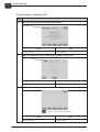
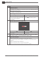
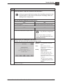
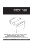
1
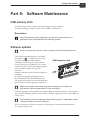
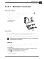
Software Manual
Control Panel
Service Guide
Software Manual
Control Panel Service Guide
Edition AG, December 2011
This manual has part No 51464
0-2
Part 0: General information
This manual
Products covered
This manual applies to the GNUC 2 control panel with finger touch display (GNUC =
Universal Processor Control System).
Intended use of this manual
The manual is meant for service personnel and contains service information regarding
trouble shooting, setup, calibration procedures, etc. The service technician should also
be familiar with the User's Guide for Control Panel as well as the Quick Intro guide.
#
This manual is for Service Technicians only.
The directions given must not be followed by unauthorized personnel.
Always read the Safety Instruction Manual part No 21741 before working
with the processor.
Whenever a reference in this manual is made to User's Guide it is meant as
"User's Guide - Control Panel".
This manual is published by:
GLUNZ & JENSEN A/S
Haslevvej 13, DK-4100 Ringsted
Denmark
Phone: +45 5768-8181
E-mail: [email protected]
Internet: www.glunz-jensen.com
Copyright © 2008 by GLUNZ & JENSEN A/S.
0918
Software Manual - Control Panel Service Guide
0-3
Reservations
• This manual was written and illustrated using the best possible information
available at the time of publication.
• Any differences between this manual and the equipment reflect improvements
introduced after the publication of the manual.
• Changes, technical inaccuracies and typographic errors will be corrected in
subsequent editions.
• As a part of our policy of continuous improvement, we reserve the right to alter
design and specifications without further notice.
Notes, Cautions, and Warnings !
Throughout the manual notes, cautions, and warnings are written in bold like the
examples below:
"
A graduate is required for pump calibration.
Symbol
"
$
#
Meaning
Note
Caution
Warning
Explanation
The operator should observe and/or act according to the
information in order to obtain the best possible function of the
equipment.
The operator must observe and/or act according to the
information in order to avoid any mechanical or electrical
damage to the equipment.
The operator must observe and/or act according to the
information in order to avoid any personnel injury.
Software Manual - Control Panel Service Guide
0918
0-4
Table of contents
Part 0:
General information . . . . . . . . . . . . . . . . . . . . . . . . . . . . 0-2
This manual. . . . . . . . . . . . . . . . . . . . . . . . . . . . . . . . . . . . . . . . . . . . . . . . . . . . . 0-2
Products covered . . . . . . . . . . . . . . . . . . . . . . . . . . . . . . . . . . . . . . . . . . . . . . . 0-2
Intended use of this manual . . . . . . . . . . . . . . . . . . . . . . . . . . . . . . . . . . . . . . . 0-2
Reservations . . . . . . . . . . . . . . . . . . . . . . . . . . . . . . . . . . . . . . . . . . . . . . . . . . 0-3
Notes, Cautions, and Warnings ! . . . . . . . . . . . . . . . . . . . . . . . . . . . . . . . . . . . . 0-3
Part 1:
Introduction . . . . . . . . . . . . . . . . . . . . . . . . . . . . . . . . . . 1-1
User Interface (UI) . . . . . . . . . . . . . . . . . . . . . . . . . . . . . . . . . . . . . . . . . . . . . . . . 1-1
Power on/off . . . . . . . . . . . . . . . . . . . . . . . . . . . . . . . . . . . . . . . . . . . . . . . . . . . . 1-1
Part 2:
Modes and access. . . . . . . . . . . . . . . . . . . . . . . . . . . . . . 2-1
Access levels . . . . . . . . . . . . . . . . . . . . . . . . . . . . . . . . . . . . . . . . . . . . . . . . . . . . 2-1
Change of access level . . . . . . . . . . . . . . . . . . . . . . . . . . . . . . . . . . . . . . . . . . . 2-1
Change of code . . . . . . . . . . . . . . . . . . . . . . . . . . . . . . . . . . . . . . . . . . . . . . . . 2-1
Modes. . . . . . . . . . . . . . . . . . . . . . . . . . . . . . . . . . . . . . . . . . . . . . . . . . . . . . . . . 2-2
Ready mode (On) (= Processor Overview). . . . . . . . . . . . . . . . . . . . . . . . . . . . . . 2-2
Sleep mode (Off) (= Power Save). . . . . . . . . . . . . . . . . . . . . . . . . . . . . . . . . . . . 2-2
Service mode / Remote service . . . . . . . . . . . . . . . . . . . . . . . . . . . . . . . . . . . . . 2-3
Part 3:
Setup . . . . . . . . . . . . . . . . . . . . . . . . . . . . . . . . . . . . . . 3-1
Introduction to setup. . . . . . . . . . . . . . . . . . . . . . . . . . . . . . . . . . . . . . . . . . . . . . . 3-1
Setup procedure . . . . . . . . . . . . . . . . . . . . . . . . . . . . . . . . . . . . . . . . . . . . . . . . . . 3-1
Configuration for extra features . . . . . . . . . . . . . . . . . . . . . . . . . . . . . . . . . . . . . 3-1
Programs . . . . . . . . . . . . . . . . . . . . . . . . . . . . . . . . . . . . . . . . . . . . . . . . . . . . 3-1
Plate sizes . . . . . . . . . . . . . . . . . . . . . . . . . . . . . . . . . . . . . . . . . . . . . . . . . . . . 3-2
Replenishment/buffer . . . . . . . . . . . . . . . . . . . . . . . . . . . . . . . . . . . . . . . . . . . . 3-2
Replace periods . . . . . . . . . . . . . . . . . . . . . . . . . . . . . . . . . . . . . . . . . . . . . . . . 3-2
Preferences . . . . . . . . . . . . . . . . . . . . . . . . . . . . . . . . . . . . . . . . . . . . . . . . . . . 3-2
Auto timer . . . . . . . . . . . . . . . . . . . . . . . . . . . . . . . . . . . . . . . . . . . . . . . . . . . . 3-2
Date/time . . . . . . . . . . . . . . . . . . . . . . . . . . . . . . . . . . . . . . . . . . . . . . . . . . . . 3-2
Language . . . . . . . . . . . . . . . . . . . . . . . . . . . . . . . . . . . . . . . . . . . . . . . . . . . . 3-3
Part 4:
Service Issues . . . . . . . . . . . . . . . . . . . . . . . . . . . . . . . . 4-1
Devices . . . . . . . . . . . . . . . . . . . . . . . . . . . . . . . . . . . . . . . . . . . . . . . . . . . . . . . . 4-1
Monitoring status of devices . . . . . . . . . . . . . . . . . . . . . . . . . . . . . . . . . . . . . . . 4-1
Test and calibration . . . . . . . . . . . . . . . . . . . . . . . . . . . . . . . . . . . . . . . . . . . . . 4-1
Repair . . . . . . . . . . . . . . . . . . . . . . . . . . . . . . . . . . . . . . . . . . . . . . . . . . . . . . . . . 4-1
Calibration. . . . . . . . . . . . . . . . . . . . . . . . . . . . . . . . . . . . . . . . . . . . . . . . . . . . . . 4-2
Pump calibration . . . . . . . . . . . . . . . . . . . . . . . . . . . . . . . . . . . . . . . . . . . . . . . 4-2
Water pump . . . . . . . . . . . . . . . . . . . . . . . . . . . . . . . . . . . . . . . . . . . . . . . . 4-3
0910
Software Manual - Control Panel Service Guide
0-5
Part 5:
Software Maintenance. . . . . . . . . . . . . . . . . . . . . . . . . . . 5-1
USB memory stick . . . . . . . . . . . . . . . . . . . . . . . . . . . . . . . . . . . . . . . . . . . . . . . . 5-1
Reservations . . . . . . . . . . . . . . . . . . . . . . . . . . . . . . . . . . . . . . . . . . . . . . . . . . 5-1
Software updates . . . . . . . . . . . . . . . . . . . . . . . . . . . . . . . . . . . . . . . . . . . . . . . . . 5-1
Back-up and Restore. . . . . . . . . . . . . . . . . . . . . . . . . . . . . . . . . . . . . . . . . . . . . . . 5-2
Screen saver . . . . . . . . . . . . . . . . . . . . . . . . . . . . . . . . . . . . . . . . . . . . . . . . . . . . 5-2
Screen dumps . . . . . . . . . . . . . . . . . . . . . . . . . . . . . . . . . . . . . . . . . . . . . . . . . . . 5-2
Part 6:
Network Connection . . . . . . . . . . . . . . . . . . . . . . . . . . . . 6-1
Network enabling . . . . . . . . . . . . . . . . . . . . . . . . . . . . . . . . . . . . . . . . . . . . . . . . . 6-1
Direct link . . . . . . . . . . . . . . . . . . . . . . . . . . . . . . . . . . . . . . . . . . . . . . . . . . . . . . 6-1
Procedure . . . . . . . . . . . . . . . . . . . . . . . . . . . . . . . . . . . . . . . . . . . . . . . . . . . . 6-1
Part 7:
Trouble Shooting . . . . . . . . . . . . . . . . . . . . . . . . . . . . . . 7-1
Initialization . . . . . . . . . . . . . . . . . . . . . . . . . . . . . . . . . . . . . . . . . . . . . . . . . . . . . 7-1
Initialization fail . . . . . . . . . . . . . . . . . . . . . . . . . . . . . . . . . . . . . . . . . . . . . . . . 7-1
Trouble Shooting - Initialization fail . . . . . . . . . . . . . . . . . . . . . . . . . . . . . . . . 7-2
Advanced trouble shooting. . . . . . . . . . . . . . . . . . . . . . . . . . . . . . . . . . . . . . . . . . . 7-8
Log files . . . . . . . . . . . . . . . . . . . . . . . . . . . . . . . . . . . . . . . . . . . . . . . . . . . . . 7-8
Procedure . . . . . . . . . . . . . . . . . . . . . . . . . . . . . . . . . . . . . . . . . . . . . . . . . . 7-8
Appendix: A . . . . . . . . . . . . . . . . . . . . . . . . . . . . . . . . . . . . . . . . . A-1
Menu structure. . . . . . . . . . . . . . . . . . . . . . . . . . . . . . . . . . . . . . . . . . . . . . . . . . . A-1
Software Manual - Control Panel Service Guide
0918
0-6
0918
Software Manual - Control Panel Service Guide
Introduction
User Interface (UI)
Part 1: Introduction
User Interface (UI)
The UI holds all processor functions, configuration, testing, and adjusting procedures.
The basic concept of the UI is described in the User's Guide. The User's Guide will give
the operator an introduction to the control panel as well as a few instructions for first
start-up procedures.
"
The descriptions given in this manual applies for "Admin" and "Service"
access levels.
"
Executing service procedures described in this manual requires change of
access level to "Service". See "Access levels" in Part 2.
Power on/off
The control panel will automatically turn on/off when power to the processor is
switched on/off.
When the processor is turned on it will start to initialize. It will then take a few
minutes until the processor overview is displayed on the screen. (The processor
overview is described in the User's Guide, Control Panel).
"
During power up the processor might give some beep advices related to
messages or alarms. These messages and alarms will be shown in the alarm
list when the processor overview is displayed. Press
to see the alarm list.
$
Power supply should only be turned off for holidays or for maintenance and
servicing purposes. Normally the processor should be switched into sleep
mode (power save) only. See the Quick Intro guide.
Software Manual - Control Panel Service Guide
0918
1-1
1-2
Introduction
Power on/off
0918
Software Manual - Control Panel Service Guide
Modes and access
Access levels
Part 2: Modes and access
Access levels
The menu system gives the operator access to menu items that are relevant according
to access level.
"
Executing service procedures described in this manual requires access level
"Service".
Service access level is required for configuration and some setup procedures and some
section menus/buttons are accessible with service access level only.
The access level can be changed between:
Access Level
The operator …
User
Can see various usage information.
Admin
Administrator has user level privileges plus access to modification of most
application relevant setup information.
Service
Full control.
$
Service Technicians only!
Change of access level
Default access level is either User or Admin (administrator). The "Change access level"
dialog can be activated from the
menu. Change of access level requires a numeric
code. Default Admin code is 2005. Default Service code is 389. Any other numbers will
change access level to User.
"
Entering an incorrect/unknown code will automatically change access level to
User.
Change of code
Administrator and Service codes can be changed from the "
Preferences -> Access setup" menu.
"
-> Settings ->
Make sure to make a note of new codes if changed and keep in a safe place
for future reference.
There will be no possibility of recovering a lost code.
Software Manual - Control Panel Service Guide
0918
2-1
2-2
Modes and access
Modes
Modes
Ready mode (On) (= Processor Overview)
The processor will normally be in either
Ready Mode or in Sleep Mode.
In ready mode the processor regulations
are all active, the Processor Overview
menu is on, and plates can be processed
if no alarms or other exceptions have
occurred (e.g. cover open). Ready mode
is indicated by the ready feed indicator
and the top lamp showing a green
light.
T2636
Regulations and functions in ready mode:
• Temperature controls are on.
• Level controls are on.
• Time replenishment function is active.
• Jog function is active. The jog function makes the transport rollers turn for a short
while at intervals to prevent crystallization of chemicals on the rollers.
Sleep mode (Off) (= Power Save)
In Sleep Mode the processor regulations
(e.g. temperatures) are all sleeping, the
Processor Overview is off. Plates cannot
be processed.
The sleep mode is indicated with a sleep
icon
in the upper left corner of the
control panel. How to switch to sleep
mode is described in the Control Panel
User's Guide.
(Example)
Functions in sleep mode:
• All processing functions are off.
• Auto timer may be active.
• Jog mode may be active.
• Possibility of entering the processors
and
menus in order to reset counters or
make changes to fill/replenishment/buffer strategy before starting up the processor.
0910
Software Manual - Control Panel Service Guide
Modes and access
Modes
Service mode / Remote service
Service mode is different from service access. Service mode enables test of devices,
calibration of pumps, etc., and gives access to remote1 control of the processor whereas
Service access gives permission to configuration parameters.
Service mode is automatically activated if service functions have been activated (when
access level is set to "Service"). Service mode can also be activated manually from the
"
-> Remote service" menu.
The service mode is indicated with a
service icon
in the upper left corner
of the control panel.
In order to leave service mode either
enter "
-> Remote service" and press
the "Exit service mode" button or press
the
button for 3 sec. Either will make
the processor restart automatically. New
settings, if any, will be stored and test
sequences will reset.
) Remote Enabling System allows remote connection to one or more GNUC based processors either via modem or
through the local network (LAN). The remote connection allows monitoring and control of the processor.
(GNUC: Universal Processor Control System)
1
Software Manual - Control Panel Service Guide
0837
2-3
2-4
Modes and access
Modes
0918
Software Manual - Control Panel Service Guide
Setup
Introduction to setup
Part 3: Setup
Introduction to setup
When mechanical and electrical installation has been completed or when new software
has been installed please follow the setup procedure below for configuration and setup
of the software.
If new software has been installed and a back-up of the processors data is available a
restore of data will make further setup unnecessary. See also "Software Maintenance"
in Part 5.
If new SOM PCB (System On Module PCB) has been installed the configuration has
been lost and the processor will start up with "Call Service Code 2". See also Part 7 in
this manual.
Setup procedure
$
Set control panel access level to "Service".
Configuration for extra features
The processor is configured from the factory. If however any extra features like level
sensors for replenish/buffer containers etc. have been installed, additional
configuration is needed in order to adapt the software to the extra features.
Check all menus/parameters listed for "
-> Settings" and "
-> Configuration" and
adjust settings where needed.
Also make sure to check all parameters in "
->Configuration -> Choices".
The list of menus in Appendix A might be helpful for this purpose.
Consult also the "Finishing installation" description in the processor's Installation
Manual.
Programs
Enter "
-> Settings -> Programs". Select "Program 1" and enter settings for speed,
dwell time, temperature, and parallel plates.
If more than one program is needed use the "Add program" menu and enter values for
"Program 2" as well etc.
The processor is preinstalled with one program, allowing the user to add up to 3
additional programs.
If more than one processing program is defined, each program will be represented by a
program button e.g.
in the title bar.
Software Manual - Control Panel Service Guide
0910
3-1
3-2
Setup
Setup procedure
Plate sizes
See description in the User's Guide, Control Panel.
Replenishment/buffer
In order to ensure good processing quality and chemistry efficiency some settings for
replenishment/buffer need to be made. Settings are made in "
-> Settings ->
Replenishment/Buffer settings", and should be made in accordance with
recommendations from the supplier of chemistry.
Replace periods
Replace periods are the max. plate area and the recommended max. process length to
be processed before alarms for change of e.g. developer solution, filter, and brush occur.
Preferences
The preferences menu holds a few additional parameters of general character e.g.
settings for display, access level, developer and water level setup. These settings do
not apply to specific processing programs.
"
Some of the parameters are available from sleep mode as well.
Auto timer
The processor can be programmed for automatic start-up and shut-down which is
switching from sleep mode to ready mode and opposite.
Settings are found in "
-> Settings".
"Start" switches the processor from sleep mode to ready mode. "Stop" switches the
processor from ready mode to sleep mode.
See also "Modes and Access" in Part 2 for detailed description of sleep mode and ready
mode.
$
Make sure that settings for date and time are correct otherwise the auto timer
function will not start the processor at the expected time.
Date/time
Date is specified as date-month-year e.g. 17-01-07. Time is specified either as 24 Hour
Clock e.g. 15:35 or as US time e.g. 3.35 pm depending on settings made for units (see "
-> Configuration -> Choices -> Units").
The date/time button can be activated from sleep mode. Press the date/time button in
the upper right corner and make settings. When settings have been made press
to
0910
Software Manual - Control Panel Service Guide
Setup
Setup procedure
confirm new date and time. In order to adjust the internal clock the processor will then
restart automatically.
$
Make sure settings for date and time are correct otherwise the auto timer
function will not start the processor at the expected time.
Language
Default language for control panel menus is English. Change of language is done from
the language dialog. Enter the "
-> Settings -> Preferences -> Display setup ->
Language".
Select new language and confirm with
. The processor will then automatically
restart.
Software Manual - Control Panel Service Guide
0918
3-3
3-4
Setup
Setup procedure
0918
Software Manual - Control Panel Service Guide
Service Issues
Devices
Part 4: Service Issues
Devices
Devices are electronically controlled components like pumps, motors, sensors, heaters,
etc. Devices entries are used for:
Monitoring status of devices
Access from Processor Overview (ready mode) either through the appropriate sub
section and then through the device sub menu or through "
-> Devices".
Test and calibration
Access to devices for test and calibration purposes is done from sleep mode. See also
"Calibration" described later in this chapter.
Repair
Spare part numbers for the control panel parts are listed in the processor service
manual.
#
All power to the processor must be
disconnected before performing
service on, or disassembling the
control panel.
Please note that where this label
appears on the processor, electrical
shock hazard still exists when main
switch is turned off.
DANGER
ELECTRICAL SHOCK HAZARD
DISCONNECT ALL EXTERNAL POWER
SUPPLY BEFORE SERVICING
TO BE SERVICED BY AUTHORIZED PERSONNEL ONLY
RISQUE DE CHOC ÉLECTRIQUE
AVANT TOUTE INTERVENTION,
DÉBRANCHER TOUTES LES SOURCES DE COURANT
MAINTENANCE PAR PERSONNEL
AUTORISÉ SEULEMENT
Software Manual - Control Panel Service Guide
0918
4-1
4-2
Service Issues
Calibration
Calibration
Pump calibration
Pumps installed on the processor may be
Section
Sub menu
Pump
Notes
Pre-wash section
Pre-wash devices
Water pump
Some models only
xxx1 section
xxx1 devices
xxx1 pump
Calibration of the pump type used
for replenish/buffer will normally not
be necessary.
Fill pump
Some models only
Water pump
Some models only
Water pump
Some models only
Wash section
Wash devices
) Section name listed here as "xxx" refers to control panel text which will vary depending on
processing technology (chemical free or traditional developer solution).
1
Make sure that pumps and hoses do not contain air bubbles.
An example of calibrating a water pump is given opposite.
0910
Software Manual - Control Panel Service Guide
Service Issues
Calibration
Water pump
$
Control panel access level must be set to "Service".
Calibration menus for pumps and valves are available through "xxx section -> xxx
devices -> xxx pump".
"
A graduated cylinder is required for pump calibration.
The example below is given for a developer water pump.
View/header
Action
Press
Processor overview
for 3 seconds to switch to sleep mode.
Some processors only: If the processor is configured for gum cleaning,
press "Stop" to skip the gum cleaning procedure.
Note the sleep mode icon
in upper left corner of the control panel.
• Remove the hose from the replenishment/buffer container for the xxx1
section and keep it elevated to avoid spill.
Sleep mode
• Place the hose in the graduated cylinder filled with xxx1 liquid.
$
Processor overview
Xxx1
Xxx1 devices
Replenish/Buffer
pump
Make a note of the amount of liquid.
• Press the
button to enter the xxx1 section menu.
• Press the "xxx1 devices" button to enter the sub menu.
• Press the "Replenish/Buffer pump" button to enter sub menu.
• Press the "Calibrate" button to enter the pump calibration dialog.
The "Repl pump capacity : xxx ml/min" (or "Buffer pump ...") button gives
access to a numeric display and the possibility of entering new pump
capacity value.
Calibrate buttons
The "Start" buttonactivates the xxx1 replenish/buffer pump. Press "Stop"
when sufficient fluid has been pumped (after 60 sec.). Make a note of the
amount of liquid pumped.
• Press "Adjust" to adjust the value if the displayed value is different from
the actual pumped volume, and add the correct value.
Press
Calibrate
. The new capacity will be calculated and stored.
• Press
in steps (or hold 1 sec. and release) to return to the Processor
Overview.
Select another section for calibration of pump, make other service
adjustments if needed, or press the
button to restart the processor.
Processor overview
" the processor return to the default access level.
Restarting will automatically switch service mode off and make
) Section name listed here as "xxx" refers to control panel text which will vary depending on
processing technology (chemical free or traditional developer solution).
1
Software Manual - Control Panel Service Guide
1114
4-3
4-4
Service Issues
Calibration
1114
Software Manual - Control Panel Service Guide
Software Maintenance
USB memory stick
Part 5: Software Maintenance
USB memory stick
A USB memory stick is required for performing software updates.
Software packages must be stored on the USB's root directory.
Reservations
"
Only USB memory sticks supplied by the processor manufacturer are
guaranteed to be compatible for the software updates.
Software updates
$
Access level must be "Service" when working with software maintenance.
The software update function is available
through the "
-> Software tools" menu
and will scan for available updates
(including a USB memory stick inserted
into the processor's USB port). The current
software version will be presented together
with available updates for optional
selection.
Restart is offered when a software update is
complete.
If a software upgrade package has been
downloaded from the manufactures web
site, please also make sure to download and
print out the software upgrade instruction.
$
USB memory stick
Make sure to make a data back-up before installing new software as
described in "Back-up and Restore" in the following.
Software upgrade is also possible through the Remote Enabling System. This requires
min. Remote Enabling System version 1.09.19 (listed in upper left corner of the Remote
Client view).
$
Downloading software using the remote client requires a USB memory stick
connected to the processor's USB port.
If for any reason a software downgrade is wanted please contact the manufacturer:
www.glunz-jensen.com
Software Manual - Control Panel Service Guide
0918
5-1
5-2
Software Maintenance
Back-up and Restore
Back-up and Restore
Creating a data back-up will ensure that all values from statistics, settings, and
configuration are stored for later restore.
$
Data back-ups are for emergency restore only.
Normally there will be no need for restoring the emergency back-up data as the
software upgrade procedure automatically covers back-up and restoring of customer
settings.
The back-up and restore functions are available through "
-> Software tools".
Back-up data can be stored either internally or on a USB memory stick.
$
Consider carefully when restoring data as this will overwrite existing data on
the processor.
• Only restore a back-up to the same processor from which it has been
made.
• Configuration file back-up will overwrite any new configuration
parameters if restored.
"
The processor restarts automatically when restore of back-up is complete.
Screen saver
Screen saver files are loaded like software update packages.
Screen dumps
Screen dumps may be useful for service
purposes. Connect a USB memory stick
to the processor's USB port as shown on
the previous page.
For storing a screen dump to the USB
memory stick press the title bar on the
control panel as shown. A weak beep
from the control panel will confirm the
dump.
0918
Software Manual - Control Panel Service Guide
Network Connection
Network enabling
Part 6: Network Connection
Network enabling
Network configuration needs to be set correctly and is available through "
->
Configuration -> Network TCP/IP". To change settings, service access level is
USB memory stick
required. See Part 2, Access levels.
The three LEDs on the SOM (System On
Module) indicate the network state:
• LINK (yellow)
• 10/100 MB (green)
• DATA (green)
P
1 1 P
2 1
Network
cable
T2644
SOM
Direct link
The direct computer link function is used to enable a direct connection from a
processor to a PC or laptop with the Remote Enabling System installed.
The Remote Enabling System allows remote monitoring and control of GNUC* based
processors.
$
Do not enable the direct link function while the processor is connected to the
house LAN (Local Area Network).
Procedure
• If not already installed, please download the Remote Enabling System from
www.glunz-jensen.com/support/download/software and install on the local PC
according to the description on the website.
• Turn off the PC.
• If a LAN cabled is connected to the processor, or the PC is connected to wireless
LAN, make sure to disconnect the cable/connection now.
• Enter "
-> Direct computer link -> Connect".
• Turn on the PC. Wait until the login dialog is displayed.
*)
Universal processor control system.
Software Manual - Control Panel Service Guide
1150
6-1
6-2
Network Connection
Direct link
• Connect a crossover network cable between the PC and the processor. Connection is
made according to illustrations below, either to the processor's electronics cabinet
(J14) or to the back of the control panel unit (the connection to the back of the control
panel unit is not possible on all models).
Network cable
T32181
Network cable
T32182
• Log on the PC.
• Start the Remote Client (shortcut icon on the desktop).
• Select 'Server Admin' (1) (see illustration below).
• Make sure the IP address 169.254.13.0 is present. If it's not, please enter the IP
address (2) and press 'Add'.
• Make sure that the server '169.254.13.0' is enabled.
• Press 'OK'.
• In the Remote Client's 'Status' field (3) the connection should appear with status
'OK'. If however, the status shows 'Disabled' (processor tab not added (4)) re-open
the 'Server Admin' and make sure that server 169.254.13.0 is enabled.
4
2
3
1
$
1150
T2658
The processor will automatically return to the original IP address if the
network cable is removed for more than 30 seconds.
Software Manual - Control Panel Service Guide
Trouble Shooting
Initialization
Part 7: Trouble Shooting
"
The electrical diagrams are located in Appendix A or B in the processor
service manual.
#
When performing any service,
maintenance, calibration, or trouble
shooting etc. it may be necessary to
override the function of the
processor’s interlock switches.
In these cases please be aware, that
the processor’s jog function may still
be active, making the drive system
run idle at intervals. There will be
no beep advise or display message.
Please note that where this label
appears on the processor, electrical
shock hazard still exists when the
main switch is turned off.
DANGER
ELECTRICAL SHOCK HAZARD
DISCONNECT ALL EXTERNAL POWER
SUPPLY BEFORE SERVICING
TO BE SERVICED BY AUTHORIZED PERSONNEL ONLY
RISQUE DE CHOC ÉLECTRIQUE
AVANT TOUTE INTERVENTION,
DÉBRANCHER TOUTES LES SOURCES DE COURANT
MAINTENANCE PAR PERSONNEL
AUTORISÉ SEULEMENT
Initialization
When the processor is turned on the main switch it starts to initialize. Bars on the
display show the initialization progress.
Initialization fail
If initialization fails or does not complete,
the displaying of the bars may freeze or keep
restarting. If this continues after power off and
on, service is needed.
Diagnosis of initialization fail is described on
the next pages.
Software Manual - Control Panel Service Guide
0918
7-1
7-2
Trouble Shooting
Initialization
Trouble Shooting - Initialization fail
Step
A
Does the processor start up showing Safe Mode ?
Example :
YES
NO
• Go to step B
• Go to step 10
B
Does the software start up displaying the software update view ?
Example :
YES
NO
• Go to step 11
1
• Go to step 1
Does the Control Panel start up with grey background and buttons ?
"
The look of the start-up view may vary.
YES
• Go to step 2
0918
NO
• Go to step 6
Software Manual - Control Panel Service Guide
Trouble Shooting
Initialization
Step
2
Does the Control Panel show the sleep icon in the upper left corner ?
YES
NO
Software is working correctly.
• Go to step 3
• Optionally check the alarm list.
3
Set Access Level to "User" :
• Press the "Data" button and enter "Change Access Level".
• Set to "0" and press "OK" to force the access level to "User".
The control panel should now show one of the service codes :
Call Service (code 1)
• Go to step 4
Call Service (code 2)
• Go to step 5
Call Service (code 3)
• Call the manufacturer's
support center: AVR
fuses not set correctly.
4
Call Service (code 1).
The processor has started in safe mode.
This happens if the processor has been shut down several times quickly in succession, or
if the processor itself shuts down quickly repeatedly, or maybe one or more PCB's cannot
be found.
•
•
•
•
•
Turn the processor main power off.
Check that all cables between circuit boards are properly connected.
Connect power plug and turn on the processor.
Check that the individual PCB's are getting power and whether any diodes are lighting.
If one or more new MFU boards have been mounted, check that the DIP switches are
set correctly according to the instruction delivered with the MFU board. If the software
supports enabling/disabling MFU boards, consider trying to disable this feature in the
configuration and see whether the software can start.
• If this does not help, call the manufacturer's support center.
Software Manual - Control Panel Service Guide
0918
7-3
7-4
Trouble Shooting
Initialization
Step
5
Call Service (code 2).
The software is not configured. This should be the case only if the SOM PCB (System On
Module PCB) has been replaced.
• Enter "Data" and change access level to Service (default is 389 but may have been
changed by a service technician).
Either configure software or restore configuration back-up:
Configure software :
Restore a back-up :
• Enter "Data -> Configuration ..." and
check "Processor variant" (some models
only) and other configuration
parameters.
6
• Enter "
-> Software tools-> Restore
data" and select a back-up version.
Does the control panel show a progress bar ?
YES
• Go to step 7
NO
• Go to step 8
7
Please note the numbers of blocks in the progress bar and note if the progress
bar restarts by itself ? Call the manufacturer's support center.
8
Check cables and power :
• Make sure the processor is configured for correct power connection.
For reference see the electrical diagram in the Appendix in the Processor's Service
Manual.
• Make sure the GFCI relay is switched on.
• Make sure the power cable is connected to the processor.
• Make sure that power supply is sufficient. Check with a voltmeter.
0918
Software Manual - Control Panel Service Guide
Trouble Shooting
Initialization
Step
9
Check electronics. Open the electronics box and check :
$
Always use grounded wrist straps when handling printed circuit
boards (PCB´s) as the effect of electrostatic discharge (ESD) can
damage these components.
Do red and green LEDs flash on HPU board ?
YES
NO
• Call the manufacturer's support center.
• Continue below.
Are the LEDs on the SOM board active?
YES
• Call the manufacturer's support center.
NO
$
Very delicate component!
• Make sure the SOM is connected
properly. Do not dismount unless it is
absolutely necessary.
10
The processor has started up in safe mode.
Display will show one of the system messages below :
Symptom: Lib component cannot be
found.
Cause:
Main power has been
turned off while updating lib
component.
Remedy:
Call the manufacturer's
support center.
Insert USB memory stick
containing qtlib.tar.gz and
lib-xxx.gjsw and restart.
System will start up as shown
in step 11.
The files are also available
on www.glunz-jensen.com/
support
Continues next page ...
Software Manual - Control Panel Service Guide
0918
7-5
7-6
Trouble Shooting
Initialization
Step
10
... continued.
Symptom: The platform parameter has
not been set.
Causes:
Possibly new SOM has been
installed.
Remedy:
Call the manufacturer's
support center.
Insert USB memory stick
containing platform.txt file
specifying the platform
code. System will start up
as shown in step 11.
Symptom: Application checksum is
correct but one or more
applications are missing.
Cause:
Software update package
not valid or damaged.
Remedy:
Call the manufacturer's
support center.
Insert USB memory stick with
correct platform.txt file and
corresponding software
installation files (*.gjsw).
Restart to force the processor
into software update. The
system will start up as shown
in step 11.
Symptom: Data flash partition could
not be found.
Cause:
Internal file error.
Remedy:
Call the manufacturer's
support center.
11
The display shows a software update views.
Platform Update view:
The display shows the platform update
view. The platform has been updated. One
or more software updates will have to be
installed. If a file is missing it will appear
with ??? (e.g. text - ???). Write down
displayed information.
Press "Continue" to get a full list of software
updates available on the USB.
(*** = Name of processor platform. Will
vary depending on processor type.)
0918
Software Manual - Control Panel Service Guide
Trouble Shooting
Initialization
Step
12
Software Update view:
The list shows the software version
available on the USB memory stick.
Select software version. The software
update will then start automatically.
Display will show update progress in
percent.
Restart the processor when software
update is complete. Ensure that any other
required updates are performed if needed.
If software is missing the processor will
start up in software update mode.
Software Checksum Error !
Software checksum error will occur if
software update has been interrupted by
e.g. power failure etc.
Press "Continue" and repeat update
procedure described in step 11.
Software Manual - Control Panel Service Guide
0918
7-7
7-8
Trouble Shooting
Advanced trouble shooting
Advanced trouble shooting
Log files
Gives access to generating and extracting log files for manufactures research.
Normal procedure is storing log files on a USB memory stick from "
tools -> Log files ...".
-> Software
If normal procedure is not accessible due to the control panel not starting the
procedure below will enable retrieving of log files.
$
This should be done only if required by manufacturers service technicians.
For use only if the control panel is not starting and retrieving logs the normal
way is therefore not possible.
Procedure
A log file retriever (two files) is needed for execution of the procedure described
below:
• Switch main power to the processor off (0).
• Copy the two files supplied by the manufacturer's support center to a USB memory
stick (the platform.txt may need to be modified to adapt to the actual processor
platform, e.g hdx).
"
Make sure that the platform.txt file matches the actual processor platform.
• Power up the processor with the USB memory stick mounted to the USB port.
• The control panel will display "Software Update" - "Platform Change".
• Press "Continue".
• Select sys-copy-log-to-usb. The platform.txt file will attempt to force the machine
into a software update mode. The sys-copy-log-to-usb is a fake update in that it
retrieves the processors log files to the USB without actually installing anything.
• Wait until the software update procedure terminates with either "ok" or "failure".
• A gnuc2log_xxxxx.tar.gz file should now be stored on the USB stick. Remove the
USB stick. Switch power off.
• Send the file to the manufacturer's support center for examination. Wait for service
assistance.
0918
Software Manual - Control Panel Service Guide
Menu structure
Appendix: A
Menu structure
Menus and parameters are grouped to where they logically belong and are often
available in more than one way. This will typically apply to menus dedicated to
processor sections. Developer counters will for instance be available both from the
menu and from the "
-> Statistics" menu. A menu available in more than one place
in the menu structure will appear with the same title no matter where it is found.
In this chapter are listed the top levels of the menu structure. Menu names followed by
"..." indicates that sub levels related to the menu in question are listed in the software.
Please refer to the control panel itself for view of these sub levels.
"
Menus/parameters in bold italics are not available/configurable for all
processor models.
Plate counters …
Displaying of processed plates, area and time
Time counters ...
Displaying various time elapsed
Settings …
Replace periods ...
Parallel plates
Speed
Transport devices …
Cover switch ...
Motor …
Conveyor busy ...
Input slot …
Output slot …
Rewash slot
Configuration …
See also
Input sensor offset
Distance from standard mounting postion.
Temperature …
Settings and readouts
Preheat devices …
See also
-> Devices
Configuration …
See also
-> Configuration
Preheat configuration
See also
-> Configuration
Software Manual - Control Panel Service Guide
-> Configuration
0910
A-1
A-2
Menu structure
Prewash counters …
See also
-> Statistics -> Counters
Brush counters ...
See also
-> Statistics -> Counters
Settings …
See also
-> Settings
Prewash devices …
See also
-> Devices
Configuration …
See also
-> Configuration
Conductivity …
See also
-> Statistics -> Conductivity
xxx counters …
See also
-> Statistics -> Counters
Brush counters …
See also
-> Statistics -> Counters
Settings …
See also
-> Settings
xxx devices …
See also
-> Devices
Configuration …
See also
-> Configuration
Wash counters …
See also
-> Statistics -> Counters
Brush counters …
See also
-> Statistics -> Counters
Settings …
See also
-> Settings
Wash devices …
See also
-> Devices
Configuration …
See also
-> Configuration
Gum counters …
See also
-> Statistics -> Counters
Settings …
See also
-> Settings
Gum devices …
See also
-> Devices
Configuration …
See also
-> Configuration
Dryer devices …
See also
-> Devices
Configuration ...
See also
-> Configuration
Help view
Press this button for information in any control panel view or
menu.
* Temperature …
Temperature …
*) Processing section with chemical free or traditional developer solution. Section name listed here
as "xxx" refers to control panel text which will vary depending on processing technology.
0910
Software Manual - Control Panel Service Guide
Menu structure
Statistics …
Counters …
Conductivity …
Event list
History …
Settings …
Programs …
Plate sizes …
Replenishment …
Buffer settings ...
Replace periods …
E.g. brush-, filter change, and
conductivity exhaustion point
Preferences …
Display setup …
Plate length tolerance …
Access setup …
Level setup …
Miscellaneous …
Auto timer …
Configuration …
Calibrate ...
Valves and pumps
Service code
Information …
Processor variant
Hardware …
Choices …
E.g. ready delay, setter
request, dwell type,
temperature alarm range,
units …
Conductivity …
Serial number …
Network - TCP/IP …
Change access level …
A numeric code is needed for change of access level.
Software Manual - Control Panel Service Guide
0910
A-3
A-4
Menu structure
Manual tasks …
Developer filter replaced
Prewash water replaced
Developer replaced
Wash water replaced
Gum replaced
Brush replaced
Prewash manual replenish …
Developer manual replenish ...
Wash manual replenish …
Major service performed
Inhouse service performed
Cleaning tasks …
Clean Gum ...
Clean Developer …
Cleaning cycle
Rewash plate
Eject plates …
Brush calibration …
Software tools …
Update software
Log files …
Back up data
Restore data
Roller motor load test
Developer brush motor load test
Remote service …
To switch the processor into service mode.
Turn rollers
Dialog for turning rollers for easy disassembling
Devices …
For checking of devices related to each processor section.
Direct computer link …
For direct connection of PC to the processor.
Settings for date and time. Accessible from sleep mode only.
0910
Software Manual - Control Panel Service Guide