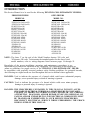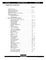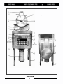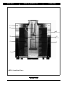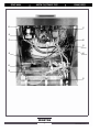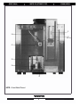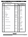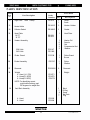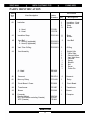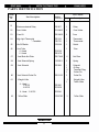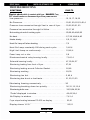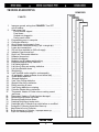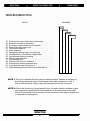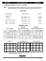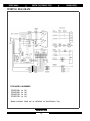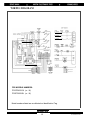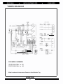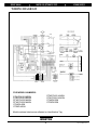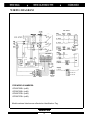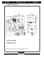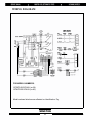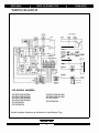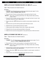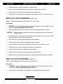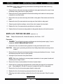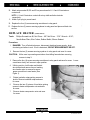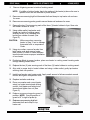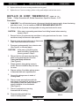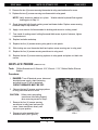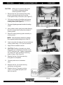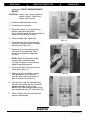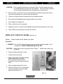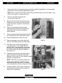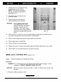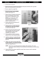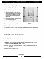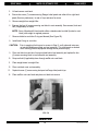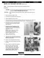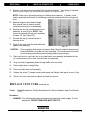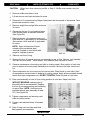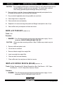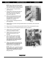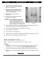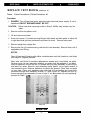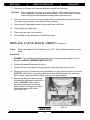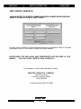
1
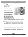
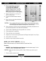
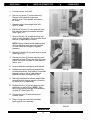
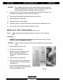
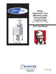
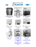
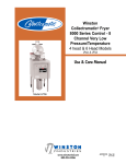
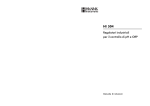
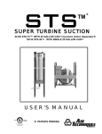
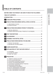
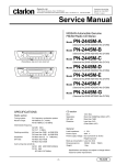
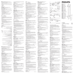
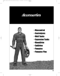
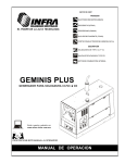
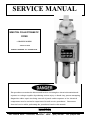
SERVICE MANUAL
WINSTON COLLECTRAMATIC
FRYER
8 CHANNEL MODELS
4 HEAD & 6 HEAD
MANUAL REORDER: LIT. 6710/REV.0/9-91
The procedures contained in this manual involve accessing bare electrical terminals and
exposure to voltages capable of producing serious injury or death. Any person attempting
diagnoisis and/or repair involving removal of panels and/or exposure to live electrical
components must be trained or experienced in such service procedures.
Disconnect
electrical service while performing the procedures listed in this manual.
WINSTON
PRODUCTS COMPANY
2345 CARTON DRIVE . LOUISVILLE, KENTUCKY . 40299 . (800) 234-5286 . FAX: (502)495-5458
INTRODUCTION
This Service Manual is to be used for the following WINSTON COLLECIRAMATIC FRYERS:
PRESSURE FRYERS
OPEN FRYERS
MODEL NO.
MODEL NO .
PFWPC4201 CASJ(or M)
PFWPC6201 CASJ(or M)
PF46P32 SJ(or M)
PF56P32 SJ(or M)
PF46P37 SJ(or M)
PF56P37 SJ(or M)
PFWPC4201 SJ(or M)
PFWPC6201 SJ(or M)
PFWPC4201 NZSN
PFWPC6201 NZSN
PFWPC4201 MASN
PFWPC6201 MASN
PF46P44 SN
PF56P44 SN
PFWPC4201 AUSN
PFWPC6201 AUSN
PF46P45SN
PF56P45SN
OFWPC4201 CASJ(or M)
OFWPC6201 CASJ(or M)
OF49P32SJ(or M)
OF59P32SJ(or M)
OF49P37SJ(or M)
OF59P37SJ(or M)
OFWPC4201 SJ(or M)
OFWPC6201 SJ(or M)
OFWPC4201 NZSN
OFWPC6201 NZSN
OFWPC4201 MASN
OFWPC6201 MASN
OF49P44 SN
OF59P44 SN
OFWPC4201
AUSN
OFWPC4201AUSN
OFWPC6201AUSN
OFWPC6201
AUSN
OF49P45
OF59 SN
OF59P45
SN
OF59P45SN
NOTE: The letter 'J' on the end of the Model Number denotes 208 volts and
'M' denotes 240 volts. To determine the intended market for the above listed
model numbers, refer to wiring diagrams listed between pages 18 through 25.
Knowledge of the proper installation, operation, and maintenence procedures is an
important step to insure safe operation of any equipment. The instructions in this manual are
meant as guidelines for proper service of the WINSTON COLLECTRAMATIC FRYER.
In accordance with generally accepted products safety labeling guidelines for potential hazards,
the following two signal words are used throughout this service manual where applicable:
DANGER: Used to indicate the presence of a hazard which could cause substantial property
damage, severe personal injury or death if warning is ignored.
CAUTION: Used to indicate the presence of a hazard which could cause minor property
damage or personal injury if warning is ignored.
DANGER: THE PROCEDURES CONTAINED IN THIS MANUAL INVOLVE ACCESSING BARE ELECTRICAL TERMINALS AND EXPOSURE TO VOLTAGES
CAPABLE OF PRODUCING SERIOUS INJURY OR DEATH. ANY PERSONS
ATTEMPTING DIAGNOSIS AND/OR REPAIR INVOLVING REMOVAL OF
PANELS AND/OR EXPOSURE TO LIVE ELECTRICAL COMPONENTS MUST
BE TRAINED OR EXPERIENCED IN SUCH SERVICE PROCEDURES.
DISCONNECT ELECTRICAL SERVICE WHILE PERFORMING THE PROCEDURES LISTED IN THIS MANUAL.
WINSTON
1
LIT.6710/REV.0/9-91
TABLE OF CONTENTS
PAGE No.
INTRODUCTION. . . . . . . . . . . . . . . . . . . . . . . . . . . . . . . . . . .1
TABLE OF CONTENTS . . . . . . . . . . . . . . . . . . . . . . . . . . . . . .2 - 3
PARTS IDENTIFICATION . . . . . . . . . . . . . . . . . . . . . . . . . . . 4 - 1 3
TROUBLESHOOTING . . . . . . . . . . . . . . . . . . . . . . . . . . . . . . 4 - 1 6
AMPERAGE / OHM VALUE CHARTS. . . . . . . . . . . . . . . . . . . 1 7
WlRlNG DIAGRAMS
PRESSURE FRYERS . . . . . . . . . . . . . . . . . . . . . . . . . . 1 8 - 2 1
OPEN FRYERS . . . . . . . . . . . . . . . . . . . . . . . . . . . . . . .2 2 - 2 5
REPLACEMENT PROCEDURES
ELECTROMECHANICAL RELAYS . . . . . . . . . . . . . . .2 6 - 2 5
MERCURY RELAY . . . . . . . . . . . . . . . . . . . . . . . . . . . 2 6 - 2 7
TRANSFORMER . . . . . . . . . . . . . . . . . . . . . . . . . . . . . 2 7
FUSE HOLDER . . . . . . . . . . . . . . . . . . . . . . . . . . . . . . .2 7 - 2 8
POWER BOARD . . . . . . . . . . . . . . . . . . . . . . . . . . . . . .2 8 - 2 9
HI LIMIT THERMOSTAT. . . . . . . . . . . . . . . . . . . . . . . 3 1 - 3 2
PROBE . . . . . . . . . . . . . . . . . . . . . . . . . . . . . . . . . . . . . 3 2 - 3 3
ON/OFF SWlTCH . . . . . . . . . . . . . . . . . . . . . . . . . . . . . 3 4
LID VALVE O-RING . . . . . . . . . . . . . . . . . . . . . . . . . . .3 4 , 3 5
LID LOCK ASSEMBLY . . . . . . . . . . . . . . . . . . . . . . . . 3 5
LID VALVE ASSEMBLY . . . . . . . . . . . . . . . . . . . . . . .3 6
HANDLEBAR . . . . . . . . . . . . . . . . . . . . . . . . . . . . . . . .3 6
HEATER HOLDER . . . . . . . . . . . . . . . . . . . . . . . . . . . .3 7
FUSE . . . . . . . . . . . . . . . . . . . . . . . . . . . . . . . . . . . . . . .3 7 - 3 8
DANGER LABEL . . . . . . . . . . . . . . . . . . . . . . . . . . . . .3 8
WHEEL . . . . . . . . . . . . . . . . . . . . . . . . . . . . . . . . . . . . .3 8
VENT ASSEMBLY . . . . . . . . . . . . . . . . . . . . . . . . . . . 3 8 - 4 0
TEFLON SLIDE . . . . . . . . . . . . . . . . . . . . . . . . . . . . . 4 0 - 4 2
COTTER PIN . . . . . . . . . . . . . . . . . . . . . . . . . . . . . . . .4 4 - 4 5
VENT TUBE O-RING . . . . . . . . . . . . . . . . . . . . . . . . . .4 4 - 4 5
WEIGHT LIFTER . . . . . . . . . . . . . . . . . . . . . . . . . . . . .4 6 - 4 7
VENT TUBE . . . . . . . . . . . . . . . . . . . . . . . . . . . . . . . . 4 7 - 4 9
WEIGHT . . . . . . . . . . . . . . . . . . . . . . . . . . . . . . . . . . . 4 9
HINGE BLOCK (REAR) . . . . . . . . . . . . . . . . . . . . . . . .4 9 - 5 1
VENT SPRING . . . . . . . . . . . . . . . . . . . . . . . . . . . . . . . 5 1 - 5 3
VENT SOLENOID . . . . . . . . . . . . . . . . . . . . . . . . . . . . 5 3 - 5 5
DRAIN VALVE . . . . . . . . . . . . . . . . . . . . . . . . . . . . . . 5 5 - 5 6
INDICATOR LAMP . . . . . . . . . . . . . . . . . . . . . . . . . . .5 6
VENT BLOCK . . . . . . . . . . . . . . . . . . . . . . . . . . . . . . . 5 7 - 5 8
LATCH BLOCK (FRONT) . . . . . . . . . . . . . . . . . . . . . . 5 7 - 5 9
MAIN CIRCUIT BOARD . . . . . . . . . . . . . . . . . . . . . . . 5 9
OBTAINING SERVICE. . . . . . . . . . . . . . . . . . . . . . . . .6 0
WINSTON
2
LIT.6710/REV.0/9-91
1
2
(Inside Lid Groove)
15
3,4,
5,6
16
7
8
17
9
18
10
11
12
19
Escutcheon
(Ref Only)
22
ID
Tag
(Ref Only)
23
13
20
24
14
21
25
WINSTON
4
LIT.6710/REV.0/9-91
26
27
28
29
31
32
30
(under)
33
High limit
Thermostat Bulb
(Refrence Only)
34
35
36
WINSTON
5
LIT.6710/REV.0/9-91
37
38
42
(If Applicable)
39
43
(Behind)
40
44
41
NOTE: 6-Head Model Picture
WINSTON
6
LIT.6710/REV.0/9-91
45
51
46
47
52
53
(Inside)
48
54
(Behind)
49
50
55
WINSTON
7
LIT.6710/REV.0/9-91
-
61
56
62
(Behind)
57
58
59
60
NOTE: 6-Head Model Pictured
WINSTON
8
LIT.6710/REV.0/9-91
PARTS IDENTIFICATION
Photo
Item
Kit Content
Part Description
Order
Number
No.
Qty. Description
1
Lid Lock
PS1449
1
Lid Lock
2
Handle Bar
PS1168
1
Handle
3
Lid Valve Assembly
PS1127
1
1
1
1
Valve Body
Spring
Retainer
O-Ring
4
Lid Valve Spring
PS1028/3
3
Spring
5
Lid Valve Retainer
PS1057
1
Retainer
6
Lid Valve O-Ring
PS1010/3
3
O-Ring
7
Danger Panel
PS1210
1
Panel
8
Latch Block (Front)
PS1399
1
3
3
3
Block
Washer
Lockwasher
Nut- Flex Lock
9
Eyebrow
PS1134
1
Eyebrow
10
'High Limit’ Indicator Lamp
PS1012/3
3
Lamp
11
‘Heat On’ Indicator Lamp
PS1012/3
3
Lamp
12
Membrane Panel
PS1748
1
Panel
13
Drain Valve
PS1066
1
1
2
2
Valve
Valve Plate
Screw
Nut
14
Collector
1
1
Collector
Heat Plate
PS1891/3
3
Gasket
PS1046
1
Lid- Pressure Lock
PS1206
PS1925
13”
11”
15
Lid Gasket
16
Lid
WINSTON
9
LIT.6710/REV.0/9-91
PARTS IDENTIFICATION
Photo
Item
Kit Content
Part Description
No.
Order
Number
Qty.
Description
17
Screw
PS1118/6
6
Screw
18
Switch Guard
PS1086
1
Guard
19
Power Indicator Lamp
PS1012/3
3
Lamp
20
Drain Valve Handle
PS1695
2
1
2
1
Screw
Handle
Nut
Bracket
21
Leg
PS1142/2
2
Leg
22
Screw
PS1241/6
6
Screw
23
Back Panel
4 - Head
6 - Head
2
Panels
PS1697
PS1698
24
Muffler
PS1152
1
Muffler
25
Wheel Assembly
PS1226/2
2
2
2
Wheel - 4"
Bolt
Nut
26
Vent Back Cap
PS1729
1
1
Cap
Nut
27
Vent Back Assembly
PS1156
1
2
2
1
1
Vent Back
Spring
Rod
Cap
Nut
28
Leg Clamp Assembly
PS1621
1
2
2
Clamp
Screw
Nut
29
Hinge Block (Rear)
PS1400
1
3
3
3
Hinge Block
Washer
Lockwasher
Nut
WINSTON
10
LIT.6710/REV.0/9-91
PARTS IDENTIFICATION
Photo
Item
Kit Content
Part Description
Order
Number
No.
Qty.
Description
30
‘High Limit’ T’Stat Clamp
PS1312
1
1
Clamp
Screw
31
Heater Holder
PS1430/3
3
Heater Holder
32
Collector Gasket
PS1892/3
3
Gasket
33
Heat Plate
14.75”
12.75”
1
Heat Plate
PS1034
PS1918
1
6
2
2
2
Heater Coil
Ferrule
Nut
Compression Nut
Washer
34
Heater Assembly
208 Volts
240 Volts
PS1147
PS1148
35
Probe Guard
PS1744
1
1
Probe Guard
Screw
36
Probe Assembly
PS1747
1
1
Probe
Washer
37
Grommet
PS1263/6
6
Grommet
38
Weight
4 - Head (14 PSI)
4 - Head(11.9PSI)
6 - Head(11.9PSI)
PS1071
PS1072
PS1073
1
Weight
1
1
4
1
1
Block
O-Ring
Screw
Nut Plate
Plug
NOTE: For identifying correct
weight when ordering, read
PSI engraved on weight lifter.
39
Vent Block Assembly
4 - Head
6 - Head
PS1026
PS1684
PS1684
WINSTON
11
LIT.6710/REV.0/9-91
PARTS IDENTIFICATION
Photo
Item
Kit Content
Part Description
Order
Number
No.
40
Insulation
4 - Head
6 - Head
Qty.
Description
1
1
2
2
Insulation - Front
Insulation - Back
Strap
Buckle
2
2
Strap
Buckle
3
Vent Ball
3
O-Ring
1
1
2
1
1
1
1
8
8
1
Weight Lifter
Teflon Slide
Solenoid Wires
Vent Weld Asm
Solenoid
Spring
Bracket
Nut
Screw
Cotter Pin
PS1031
PS1792
41
Insulation Strap
PS1219/2
42
Vent Ball
4 - Head (If applicable)
6 - Head (If applicable)
PS1003/3
PS1685/3
43
Vent Tube O-Ring
PS1005/3
44
Vent Assembly
4 - Head
6 - Head
PS1458
PS1686
45
Grommet
PS127l/6
6
Grommet
46
Mercury Relay
PS1448
1
Relay
47
Circuit Board - Power
PS1800
1
Circuit Board
48
Transformer
PS1687
1
Transformer
49
Buzzer
PS1586
1
Buzzer
1
Computer
50
Computer
General Market
KFC (All markets excluding Canada)
KFC (Canada)
PS1745
PS1927
PS1848
WINSTON
12
LIT.6710/REV.0/9-91
PARTS IDENTIFICATION
Photo
Item
Kit Content
Part Description
No.
Order
Number
Qty.
Description
51
Electromechanical Relay
PS1007
1
Relay
52
Fuse Holder
PS1096/2
2
Fuse Holder
53
Fuse Kit
PS1095/6
6
Fuse
54
High Limit Thermostat
"
"
" Canadian
PS1184
PS1731
1
1
Thermostat
Thermostat
55
On/Off Switch
PS1529
1
Switch
56
Vent Tube
4 - Head
6 - Head
1
Tube
PS1322
PS1678
57
Vent Block Nut Plate
PS1704/6
6
Nut Plate
58
Vent Solenoid Spring
PS1320/3
3
Spring
59
Vent Solenoid
PS1088
1
1
2
1
Solenoid
O-Ring
Terminal Ring
Cotter Pin
60
Vent Solenoid Cotter Pin
PS1121/3
3
Cotter Pin
61
Weight Lifter
1
1
Weight Lifter
Teflon Slide
3
Teflon Slide
62
4 - Head
11.9 PSI
14.0 PSI
PS1040
PS1039
6 - Head - 11.9 PSI
PS1041
PS1075/3
PS1075/3
Teflon Slide
WINSTON
13
LIT.6710/REV.0/9-91
TROUBLESHOOTING
SYMPTOMS
FAULTS
Electric shock while in contact with fryer. DANGER:. .Turn
............. 1
OFF circuit breaker or disconnect fryer from power source
Low pressure . . . . . . . . . . . . . . . . . . . . . . . .. . . . . . . . . .15,16,17,18,22
No Pressure . . . . . . . . . . . . . . . . . . . . . . . . . . . . . . . . .19,21,20,22,23,40,4
Pressure loss excessive through Vent in rear of fryer. . . . .19,22,20,21,23
Pressure loss excessive through Lid Valve. . . . . . . . . . . . . 16,17,43
Not venting at end of cooking cycle . . . . . . . . . . . . . . . . . . . . . . . 20,25,43,44,45,23
No heat . . . . . . . . . . . . . . . . . . . . . . . . . . . . . . . . . . . . . . . . . . . 2,7,39,14,46,4,40
Heats slowly. . . . . . . . . . . . . . . . . . . . . . . . . . .. . . . . . . . . . . . 2,5,11,14,6
Heat On Lamp off when heating. . . . . . . . . . . . . . . . . . . . . . . . . . 7,9
Heat On Lamp constantly ON during cook cycle. . . . . .
3,46,4
High Limit Lamp on continuously. . . . . . . . . . . . . . . . . . .
10,46,4
Power Lamp out or dim.. . . . . . . . . . . . . . . . . . . . . . . . . . . . . . . . . .
2,9
Electromechanical relay buzzing loudly. . . . . . . . . . . . .
7,24,14
Solenoid buzzing loudly. . . . . . . . . . . . . . .. . . . . . . . . . .
47,20,24,37
Shortening leaking from front of fryer. . . . . . . . . . . . . . . . . . 27,28
Shortening leaking around Collector Gasket. . . . . . . . . . . .
26,48
Shortening smoking . . . . . . . . . . . . . . . . . . . . . . . . . . . . . .29,30
Shortening too hot. . . . . . . . . . . . . . . . . . . . . . . . . . . . .3,42,4
Shortening has burnt or bad taste. . . . . . . . . . . . . . . . . . 31,30,13,33
Shortening foaming excessively. . . . . . . . . . . . . . . . . . 30
Shortening breaking down too quickly. . . . . . . . . . . . .
36,31,12,13,8
Shortening boils over. . . . . . . . . . . . . . . . . . . . . . . . . . . . . . . . .
32,33,34,35,38
“Probe”displayed in window. . . . . . . . . . . . . . . . . . . . . .
49,42,39,4
No Display in window. . . . . . . . . . . . . . . . . . . . . . . . . . 7,41,4
Fryer stops heating between170-230 on display . . . . . . . . . . .
50,51
Display shows ‘H 2 O .' . . . . . . . . . . . . . . . . . . . . . . . . . . . . . . . . . . . . . . . 50,51
WINSTON
14
LIT.6710/REV.0/9-91
TROUBLESHOOTING
REMEDIES
CLEAN
FAULTS
ADJUST
REPAIR
REPLACE
1
Improper ground, wiring short DANGER: Turn OFF
circuit breaker. . . . . . . . . . . . . . . . . . . . . . . . . . . . . . . . . . . .
2. Open power line
Circuit breaker tripped. . . . . . . . . . . . . . . . . . . . . . . . . . . .
Fuse blown . . . . . . . . . . . . . . . . . . . . . . . . . . . . . . . . . . . .
Cordset not plugged in . . . . . . . . . . . . . . . . . . . . . . . . . . .
Faulty power switch. . . . . . . . . . . . . . . . . . . . . . . . . . . . . .
3. Programming error in computer. . . . . . . . . . . . . . . . . . . . . . .
4. Computer defective. . . . . . . . . . . . . . . . . . . . . . . . . . . . . . . .
5. One of three circuits open in fryer. . . . . . . . . . . . . . . . . . . . .
6. Heater wires connected wrong (3 ph. vs single ph). . . . . . . .
7. Loose wire connections. . . . . . . . . . . . . . . . . . . . . . . . . . . . .
8. 208 volt fryer installed on 240 volt supply. . . . . . . . . . . . . . .
9. Indicator Lamp burned out. . . . . . . . . . . . . . . . . . . . . . . . . . .
10. High Limit Thermostat defective. . . . . . . . . . . . . . . . . . . . . .
11. Heater(s) burned out. . . . . . . . . . . . . . . . . . . . . . . . . . . . . . .
12. Heaters misaligned. . . . . . . . . . . . . . . . . . . . . . . . . . . . . . . .
13. Heater(s) out of holders and touching. . . . . . . . . . . . . . . . . .
14. Electromechanical Relay Defective. . . . . . . . . . . . . . . . . . . .
15. Lid Gasket defective. . . . . . . . . . . . . . . . . . . . . . . . . . . . . . .
16. Lid Valve O-Ring not seating, defective. . . . . . . . . . . . . . . . .
17. Lid Valve Retainer loose. . . . . . . . . . . . . . . . . . . . . . . . . . . .
18. Weight dirty. . . . . . . . . . . . . . . . . . . . . . . . . . . . . . . . . . . . . .
19. Lost Vent Ball under weight in vent assembly
(if applicable - newer systems do not utilize ball). . . . . . . . .
20. Power Board defective. . . . . . . . . . . . . . . . . . . . . . . . . . . . . .
21. Solenoid defective. . . . . . . . . . . . . . . . . . . . . . . . . . . . . . . . .
22. Vent Tube O-Ring defective.. . . . . . . . . . . . . . . . . . . . . . . . .
23. Weight Lifter dirty or defective. . . . . . . . . . . . . . . . . . . . . . . .
24. Relay mounting is loose. . . . . . . . . . . . . . . . . . . . . . . . . . . . .
25. Vent Spring defective or missing. . . . . . . . . . . . . . . . . . . . . .
26. Collector Gasket dirty or defective. . . . . . . . . . . . . . . . . . . . .
27. Thermostat, Heater or Probe nuts on cooking vessel
wall loose. . . . . . . . . . . . . . . . . . . .. . . . . . . . . . . . . . . . . . . .
28. Thermostat, Heater or Probe ferrules damaged. . . . . . . . . . .
29. Shortening level below top heater . . . . . . . . . . . . . . . . . . . . .
30. Shortening badly broken down. . . . . . . . . . . . . . . . . . . . . . . .
31. Crackling build-up on heater coils. . . . . . . . . . . . . . . . . . . . .
32. Cracklings left in Collector from night before or overfilled. . .
33. Contents of Collector stirred after warm-up. . . . . . . . . . . . . .
34. Heat Plate left out of Collector. . . . . . . . . . . . . . . . . . . . . . . .
35. Solid shortening in Collector - improper warm-up. . . . . . . . .
36. Fryer not cleaned properly. . . . . . . . . . . . . . . . . . . . . . . . . . .
WINSTON
15
LIT.6710/REV.0/9-91
TROUBLESHOOTING
FAULTS
REMEDIES
CLEAN
ADJUST
REPAIR
REPLACE
37.
38.
39.
40.
41.
42.
43.
44.
45.
46.
47.
48.
49.
50.
51.
Cotter pin too long or tight (must rotate freely). . . . . . . . . . .
Excessive moisture in shortening . . . . . . . . . . . . . . . . . . . .
Pin loose in molex connector on computer . . . . . . . . . . . . . .
Power board plug loose or off . . . . . . . . . . . . . . . . . . . . . . .
Transformer defective . . . . . . . . . . . . . . . . . . . . . . . . . . . . .
Probe defective. . . . . . . . . . . . . . . . . . . . . . . . . . . . . . . . . .
Shortening/crackling build up in vent tube. . . . . . . . . . . . . . .
Vent Ball stuck on Vent Block (if applicable). . . . . . . . . . . . .
Vent solenoid cotter pin missing. . . . . . . . . . . . . . . . . . . . . .
Mercury relay defective. . . . . . . . . . . . . .. . . . . . . . . . . . . .
Vent solenoid dirty. . . . . . . . . . . . . .. . . . . . . . . . . . . .. . . .
Collector Out of round - defective. . . . . . . . . . . . . .. . . . . . . .
Probe wire(s) disconnected from plug. . . . . . . . . . . . . . . . . .
Fryer filled with water (See Note 1). . . . . . . . . . . . . .. . . . . . .
Solid shortening being melted in fryer (See Note 2). . . . . . . .
*
*
*
*
*
*
*
*
*
*
*
*
*
*
NOTE 1: This fryer is equiped with an AquaLertTMsoftware system. Software is designed to
stop the heat-up process prior to boiling point when water is detected in fryer. If
fryer is filled with water, empty, clean, dry thoroughly and fill with cooking oil.
NOTE 2: When solid shortening is being heated in fryer, the water detection software system
may respond as though water is being heated due to the slower heat curve experienced. When heating solid shortening, remove any pieces which may be lodged next
to temperature sensing probe.
WINSTON
16
LIT.6710/REV.0/9-91
AMPERAGE/OHM VALUE CHARTS
NOTE:
Resistance measurements are taken across coil of relays and terminal ends on
heaters. Wires must be removed from component prior to resistance check.
OHM CHART
DESCRIPTION
OHMIC VALUE
PART NO
Mercury Relay
Watlow
Duracool
690.0 OHMS +/- 10%
500.0 OHMS +/- 10%
PS1448
PS1448
Electromechanical Relay
225.0 OHMS +/- 10%
PS1007
Heater - 208V, 3500W
12.3 OHMS +/- 10%
PS1147
Heater - 240V, 3500W
16.4 OHMS +/- 10%
PS1148
AMPERAGE CHART
USA & CANADA
ENGLAND/
MALAYSIA/SINGAPORE
ENGLAND/
MALAYSIA/SINGAPORE
LINE
HEATER
PHASE VOLTAGE CURRENT CURRENT
(AMPS)
(AMPS)
LINE
HEATER
PHASE VOLTAGE CURRENT CURRENT
(AMPS)
(AMPS)
LINE
HEATER
PHASE VOLTAGE CURRENT CURRENT
(AMPS)
(AMPS)
1
3
208
-
-
240
43.7
14.6
208
29.2
16.8
240
25.2
14.6
1
220
240
40.1
43.7
3
-
-
AUSTRALIA
-
13.4
14.6
-
-
-
1
3
NEW ZEALAND
LINE
HEATER
PHASE VOLTAGE CURRENT CURRENT
(AMPS)
(AMPS)
-
-
-
-
-
-
380
13.4
13.4
416
14.6
14.6
SOUTH AFRICA
LINE
HEATER
PHASE VOLTAGE CURRENT CURRENT
(AMPS)
(AMPS)
LINE
HEATER
PHASE VOLTAGE CURRENT CURRENT
(AMPS)
(AMPS)
1
-
-
-
1
-
-
-
1
-
3
416
14.6
14.6
3
400
13.9
13.9
3
380
CAUTION:
13.4
13.4
208 Volt Fryers are not to be used in single phase applications. Current produced
exceeds acceptable standards.
WINSTON
17
LIT.6710/REV.0/9-91
WIRING DIAGRAM
FOR MODELS NUMBERS:
PF46P32SJ
PF56P32SJ
PF46P37SJ
PF56P37SJ
(or
(or
(or
(or
M)
M)
M)
M)
Model numbers listed are as reflected on Identification Tag.
WINSTON
18
LIT.6710/REV.0/9-91
WIRING DIAGRAM
FOR MODELS NUMBERS:
PFWPC4201SJ (or M)
PFWPC6201SJ (or M)
Model numbers listed are as reflected on Identification Tag.
WINSTON
19
LIT.6710/REV.0/9-91
WIRING DIAGRAM
FOR MODELS NUMBERS:
PFWPC4201CASJ (or M)
PFWPC6201CASJ (or M)
Model numbers listed are as reflected on Identification Tag.
WINSTON
20
LIT.6710/REV.0/9-91
WIRING DIAGRAM
FOR MODELS NUMBERS:
PFWPC4201AUSN
PFWPC6201AUSN
PF46P45SN
PF56P45SN
PFWPC4201NZSN
PFWPC6201NZSN
PFWPC4201MASN
PFWPC6201MASN
PF46P44SN
PF56P44SN
Model numbers listed are as reflected on Identification Tag.
WINSTON
21
LIT.6710/REV.0/9-91
WIRING DIAGRAM
FOR MODELS NUMBERS:
OF49P32SJ
OF59P32SJ
OF49P37SJ
OF59P37SJ
(orM)
(orM)
(orM)
(orM)
Model numbers listed are as reflected on Identification Tag.
WINSTON
22
LIT.6710/REV.0/9-91
WIRING DIAGRAM
FOR MODELS NUMBERS:
OFWPC4201SJ (or M)
OFWPC6201SJ (or M)
Model numbers listed are as reflected on Identification Tag.
WINSTON
23
LIT.6710/REV.0/9-91
WIRING DIAGRAM
FOR MODELS NUMBERS:
OFWPC4201CASJ (or M)
OFWPC6201CASJ (or M)
Model numbers listed are as reflected on Identification Tag.
WINSTON
24
LIT.6710/REV.0/9-91
WIRING DIAGRAM
FOR MODELS NUMBERS:
OFWPC4201NZSN
OFWPC6201NZSN
OFWPC4201MASN
OFWPC6201MASN
OF49P44SN
OF59P44SN
OFWPC4201AUSN
OFWPC6201AUSN
OF49P45SN
OF59P45SN
Model numbers listed are as reflected on Identification Tag.
WINSTON
25
LIT.6710/REV.0/9-91
REPLACE ELECTROMECHANICAL RELAY (ITEM N0.51)
Tools: Phillips Screwdriver #2; Slotted Screwdriver.
Procedure:
1.
DANGER: Turn off electrical power and disconnect electrical power supply. If unit is
hardwired, CIRCUIT BREAKER MUST BE OFF.
2. Remove the two (2) screws securing eyebrow to relay panel and save for reuse.
CAUTION:
Utilize care in preventing escutcheon from falling forward when removing
screws in Step 3.
3. Remove the four (4) screws securing escutcheon to relay panel and save for reuse. Lower
escutcheon slowly until secure in open position.
4. Remove relay wires. NOTE: Mark each wire location to ensure proper connection to new
relay.
5. Remove the four (4) screws securing relay to panel and save for reuse.
6. Replace the four (4) screws securing new relay to panel.
7. Observing wire location markings, connect wires to proper relay terminals.
8. Replace the four (4) screws securing escutcheon to relay panel.
9. Replace the two (2) screws securing eyebrow to relay panel and place unit back into service.
REPLACE MERCURY RELAY (ITEM NO. 46)
Tools:
Phillips Screwdriver #2; Slotted Screwdriver.
Procedure:
1.
DANGER : Turn off electrical power and disconnect electrical power supply. If unit is
hardwired, CIRCUIT BREAKER MUST BE OFF.
2. Remove the two (2) screws securing eyebrow to relay panel and save for reuse.
CAUTION:
Utilize care in preventing escutcheon from falling forward when removing
Screws in Step 3.
3. Remove the four (4) screws securing escutcheon to relay panel and save for reuse. Lower
escutcheon slowly until secure in open position.
4. Remove relay wires. NOTE: Mark each wire location to ensure proper connection to
new relay.
5. Remove the four (4) screws securing relay to panel and save for reuse.
WINSTON
26
LIT.6710/REV.0/9-91
6.
Replace the four (4) screws securing new relay to panel.
7.
Observing wire location markings, connect wires to proper relay terminals.
8.
Replace the four (4) screws securing escutcheon to relay panel.
9.
Replace the two (2) screws securing eyebrow to relay panel and place unit back into service.
REPLACE TRANSFORMER (ITEM NO. 48)
Tools:
Phillips Screwdriver #2; Nut Driver -3/8”; Wire Cutters.
Procedures:
1.
DANGER: Turn off electrical power and disconnect electrical power supply. If unit is
hardwired, CIRCUIT BREAKER MUST BE OFF.
2.
Remove the two (2) screws securing eyebrow to relay panel and save for reuse.
CAUTION:
Utilize care in preventing escutcheon from falling forward when removing
screws in step 3.
3.
Remove the four (4) screws securing escutcheon to relay panel and save for reuse. Lower
escutcheon slowly until secure in open position.
4.
Remove wire tie securing transformer wires to main harness.
5.
Disconnect the two (2) transformer plugs from harness plugs.
6.
Remove the two (2) nuts securing transformer to escutcheon and save for reuse.
7.
Replace the two (2) nuts securing new transformer to escutcheon.
8.
Insert the two (2) transformer plugs into harness plugs.
9.
Replace the four (4) screws securing escutcheon to relay panel.
10.
Replace the two (2) screws securing eyebrow to relay panel and place unit back into service.
REPLACE FUSE HOLDER (ITEM NO. 52)
Tools: Phillips Screwdriver #2; Slotted Screwdriver; Wrench-5/16”
Procedure:
1.
DANGER: Turn off electrical power and disconnect electrical power supply. If unit is
hardwired, CIRCUIT BREAKER MUST BE OFF.
2.
Remove the two (2) screws securing eyebrow to relay panel and save for reuse.
WINSTON
27
LIT.6710/REV.0/9-91
CAUTION: Utilize care in preventing escutcheon from falling forward when removing
screws in Step 3.
3.
Remove the four (4) screws securing escutcheon to relay panel and save for reuse. Lower
escutcheon slowly until secure in open position.
4.
Remove the two (2) wires attached to fuse holder marking wire locations to ensure proper
connection to new fuse holder.
5.
Remove the two (2) screws securing fuse holder to relay panel. Save screws and nuts for
reuse.
6.
Replace the two (2) screws and nuts securing new fuse holder to relay panel.
7.
Observing wire location markings, connect fuse wire to proper fuse terminals.
8.
Replace the four (4) screws securing escutcheon to relay panel.
9.
Replace the two (2) screws securing eyebrow to relay panel and place unit back into service.
REPLACE POWER BOARD
Tools:
(ITEM N0. 47)
Phillips Screwdriver #2; Slotted Screwdriver; Nut Driver - 5/16”.
Procedure:
1.
DANGER: Turn off electrical power and disconnect electrical power supply. If unit is
hardwired, CIRCUIT BREAKER MUST BE OFF.
2.
Remove the two (2) screws securing eyebrow to relay panel and save for reuse.
CAUTION: Utilize care in preventing escutcheon from falling forward when removing screws
instep 3.
3.
Remove the four (4) screws securing escutcheon to relay panel and save for reuse. Lower
escutcheon slowly until secure in open position.
4.
Unplug the 3-pin connector from power board.
NOTE: Mark wire locations to ensure proper connection to new power board and
contactor prior to Steps 5 and 6.
5.
Remove the three (3) wires attached to bottom of power board.
6.
Follow the four (4) wires from right hand side of power board and remove from termination
point. Wires labeled El, E2 and E3 connect to contactor #l and E4 to relay panel.
7.
Remove the four (4) nuts securing power board to relay panel.
8.
Replace the four (4) nuts securing new power board to relay panel.
9.
Observing wire location markings, replace the three (3) wires removed in Step 5 to power
board.
WINSTON
28
20
LIT.6710/REV.0/9-91
10. Attach wires marked El, E2 and E3 on power board to Ll. L2 and L3 terminals on
contactor #l.
NOTE: Ll, L2 and L3 terminals on contactor #l are top, middle and bottom terminals
respectively.
11. Attach 3-pin plug to power board.
12. Replace the four (4) screws securing escutcheon to relay panel.
13 Replace the two (2) screws securing eyebrow to relay panel and place unit back into
service.
REPLACE HEATER
Tools:
(ITEM N0.34)
Phillips Screwdriver #2; Nut Driver - 3/8" Nut Driver - 7/16”. Wrench - 9/16";
Needle Nose Pliers; Wire Cutters; Rubber Mallet; Silicone Sealant.
Procedure:
1.
DANGER: Turn off electrical power, disconnect electrical power supply, drain
shortening and allow to cool. If unit is hardwired, CIRCUIT BREAKER MUST BE OFF.
2.
Remove the two (2) screws securing eyebrow to relay panel and save for reuse.
CAUTION: Utilize care in preventing escutcheon from falling forward when removing
screws in step 3.
3.
Remove the four (4) screws securing escutcheon to relay panel and save for reuse. Lower
escutcheon slowly until secure in open position.
4.
Utilizing caution, hold heater end behind
wire terminal and remove hex nut marking
wire location prior to removal to ensure
proper connection to new heater (See
Figure 1).
5.
Rotate insulation strap gaining access to
buckle. Remove insulation strap and save
for reuse.
6.
Remove the two (2) pieces of insulation gaining
access to heater compression nuts and save
for reuse.
7.
Remove heater compression nuts and save
for reuse.
FIG.1
WINSTON
29
LIT.6710/REV.0/9-91
8.
Remove lid gaining access to inside of cooking vessel.
NOTE: If middle or bottom heater has to be replaced, the heater(s) above the one in
question must also be removed to permit access.
9. Remove screw securing high limit thermostat bulb and clamp to top heater coil and save
for reuse.
10. Remove screw securing probe guard to second heater coil and save for reuse.
11. Remove the two (2) nuts securing each of the three (3) heater holders to fryer. Save nuts
and heater holders for reuse.
12. Using rubber mallet, tap heater ends
forward on inside of cooking vessel
allowing ferrule to be unseated from
bushing on outside of vessel (See
Figure 2).
CAUTION:
Utilize care when removing
heater in Step 13 not to damage
thermostat bulb or temperature
Probe.
13. Using wire cutters, remove ferrules from
both heater ends and remove heater.
Note position of offset in heater between
terminal ends to ensure proper installation
of new heater.
FIG. 2
14. Positioning offsets in proper location, place new heater in cooking vessel inserting ends
through existing heater holes.
15. Replace the two (2) nuts securing each of the three (3) heater holders to cooking vessel.
16. Align coils to proper slots in heater holders and using a rubber mallet, gently tap heaters
securing them into position.
17. Install new ferrules onto heater ends. Apply small amount of silicone sealant around
ferrules and tighten compression nuts.
18. Replace insulation and strap.
19. Place new washer and correct heater
wire(s) on heater terminal and utilizing
caution, hold heater end behind wire
terminal and tighten hex nut (See
Figure 3).
20. Replace screw securing probe guard in
position. NOTE: Correct position of
guard is l/4” to right of probe tip.
21. Replace screw securing high limit
thermostat bulb and clamp to top
heater coil.
WINSTON
30
FIG.3
LIT.6710/REV.0/9-91
22.
Replace the four (4) screws securing escutcheon to relay panel.
23.
Replace the two (2) screws securing eyebrow to relay panel and place unit back into service.
REPLACE Hi LIMIT THERMOSTAT
Tools:
(ITEM N0. 54)
Phillips Screwdriver #2; Slotted Screwdriver; Open End Wrench - 9/16”.
Procedure:
1.
DANGER: Turn off electrical power, disconnect electrical power supply, dram shortening
and allow to cool. If unit is hardwired, CIRCUIT BREAKER MUST BE OFF.
2.
Remove the two (2) screws securing eyebrow to relay panel and save for reuse.
CAUTION:
3.
Utilize care in preventing escutcheon from falling forward when removing
screws in Step 3.
Remove the four (4) screws securing escutcheon to relay panel and save for reuse. Lower
escutcheon slowly until secure in open position.
4. Remove screw securing locking arm to thermostat
shaft. Save screw and arm for reuse.
5. Disconnect probe assembly from extension wire
(See Figure 6 on following page).
CAUTION:
Utilize care in preventing relay
panel from falling forward when
removing screws in Step 5.
6. Remove the four (4) screws securing relay
panel to side panels and save for reuse.
Lower panel slowly until secure
(See Figure 4).
7.
Rotate insulation strap gaining access to
buckle. Remove insulation strap and save
for reuse.
8.
Remove section of insulation gaining access
to thermostat bulb and compression nut.
9.
Remove lid gaining access to inside of
FIG. 4
cooking vessel.
10.
Remove screw securing thermostat bulb
and clamp to top heater coil and save for reuse.
Note position of bulb and clamp to ensure
proper installation of new thermostat
(See Figure 5).
11.
Remove compression nut securing
thermostat bulb to bushing.
12.
Remove bushing and bulb
extract
from
inside of cooking vessel.
FIG. 5
WINSTON
31
LIT.6710/REV.0/9-91
13. Remove the two (2) screws securing thermostat to relay panel and save for reuse.
14. Replace the two (2) screws securing new thermostat to relay panel.
NOTE: Verify aluminum washer is in place.
bushing prior to Step 14.
Washer should be placed flush against
15.
Route thermostat bulb through cooking vessel and heater holder. Replace screw securing
bulb and clamp to top heater coil.
16.
Apply a small amount of silicone sealant to bushing and secure to cooking vessel.
17.
From inside of cooking vessel, holding thermostat bulb secure at point of entrance, tighten
compression nut.
18. Replace insulation and strap.
19.
Replace the four (4) screws securing relay panel to side panels.
20.
Slide locking arm over thermostat shaft and replace screw securing arm to relay panel.
21.
Replace the four (4) screws securing escutcheon to relay panel.
22.
Replace the two (2) screws securing eyebrow to relay panel and place unit back into
service.
REPLACE PROBE (ITEM NO. 36)
Tools:
Phillips Screwdriver #2; Wrench - 9/16”; Wrench - 11/16”; Rubber Mallet; Silicone
Sealant.
Procedures:
1. DANGER: Turn off electrical power, disconnect
electrical power supply, drain shortening
and allow to cool. If unit is hardwired
CIRCUIT BREAKER MUST BE OFF.
2.
Remove the two (2) screws securing eyebrow
to relay panel and save for reuse.
CAUTION:
Utilize care in preventing
escutcheon from falling forward
when removing screws in Step 3.
3. Remove the four (4) screws securing
escutcheon to relay panel and save for
reuse. Lower escutcheon slowly until
secure in open position.
4. Disconnect probe assembly from
extension wires (See Figure 6).
FIG. 6
WINSTON
32
LIT.6710/REV.0/9-91
CAUTION: Utilize care to prevent relay panel
from falling unsupported when
removing screws in Step 5.
5.
Remove the four (4) screws securing relay
panel to side panels and save for reuse.
Lower panel slowly until secure (See Figure 7).
6.
Pull down top edge of insulation and remove
compression nut securing probe assembly to
cooking vessel (See Figure 8).
7.
Remove lid gaining access to inside of cooking
vessel.
8.
Using rubber mallet, gently tap probe allowing
ferrule to unseat from bushing on outside of
cooking vessel.
9.
Remove bushing securing probe assembly to
cooking vessel.
FIG. 7
NOTE: Verify aluminum washer is seated
flush against probe bushing prior to Step 10.
10.
Insert new probe into hole and secure bushing to
cooking vessel using 11/16” open end wrench.
11.
Apply silicone sealant to ferrule.
12.
CAUTION: Position of probe tip is critical.
Align probe tip to where bend in probe occurs
at 3/8" from fryer wall. Tighten compression
nut using 9/16” open end wrench securing
probe in place. (See Figure 9).
13.
Replace the four (4) screws securing
relay panel to side panels.
14.
Connect probe wires to extension
wires.
15.
Replace the four (4) screws securing
escutcheon to relay panel.
16.
Replace the two (2) screws securing
_ _
eyebrow to relay panel and place unit
back into service.
WINSTON
33
FIG. 8
FIG. 9
LIT.6710/REV.0/9-91
REPLACE ON/OFF SWITCH (ITEM NO.55)
Tools:
Nut Driver-5/8”; Phillips Screwdriver #2.
Procedure:
1. DANGER : Turn off electrical power and disconnect electrical power supply. If unit is
hardwired, CIRCUIT BREAKER MUST BE OFF.
2.
Remove the two (2) screws securing eyebrow to relay panel and save for reuse.
3.
Remove the four (4) screws securing escutcheon to relay panel and save for reuse.
CAUTION:
4.
Utilize care to prevent escutcheon from falling forward when removing these
screws. Lower escutcheon slowly until secure in open position.
Remove hex nut securing power switch to escutcheon. Remove switch guard from switch.
Save switch guard for reuse.
5. Remove old power switch from escutcheon. DO NOT REMOVE WIRES FROM
SWITCH AT THIS TIME.
6.
Position new power switch in escutcheon and adjust knurled nut to allow proper extension
of switch stem beyond escutcheon.
7.
Position switch guard on switch stem, replace and tighten hex nut being certain to keep
switch guard straight.
8.
Hold old power switch beside new, and working left to right, transfer wires to new power
switch
9.
Replace the four (4) screws securing escutcheon to relay panel.
10.
Replace the two (2) screws securing eyebrow to relay panel and place unit back into
service.
REPLACE LID VALVE O-RING (ITEM NO. 6)
Tools:
Slotted Screwdriver - l/8”.
Procedure:
1.
DANGER: Turn off electrical power and disconnect electrical power supply. If unit is
hardwired,
CIRCUIT BREAKER MUST BE OFF.
WINSTON
34
LIT.6710/REV.0/9-91
2.
Move or rotate handle bar to open position. Lift lid above front block and remove from
fryer. Depress lid lock removing handle bar from lid and save for reuse.
3.
Remove lid lock from lid assembly and save for reuse.
4.
Lift lid and hold valve body with other hand. Grasp the lid valve retainer with the other
hand and twist counter-clockwise to loosen.
5.
Remove lid valve retainer. Note that lid valve spring has closed coil on one end and open
coil on the other. Open end goes toward lid. Save retainer and spring for reuse.
6.
Remove lid valve and lower lid.
7.
Using slotted screwdriver, carefully remove defective O-ring from groove in valve body.
8.
Install new O-ring carefully pressing into groove in valve body.
9.
Raise lid and insert lid valve into hole in lid. Make sure groove for lid lock is toward front.
Lean lid toward back of fryer.
10.
Holding valve body secure with one hand, install spring, (open coil toward lid). Using
other hand turning clockwise, carefully screw retainer into valve body. Utilizing only
hand pressure, completely tighten retainer to lid valve.
11.
Lower lid and insert lid lock into groove in lid valve.
12.
Depress lid lock, replace handle bar and place unit back into service.
REPLACE LID LOCK ASSEMBLY (ITEM NO. 1)
Tools:
N/A
Procedure:
1. DANGER: Turn off electrical power and disconnect electrial power supply. If unit is
hardwired, CIRCUIT BREAKER MUST BE OFF.
2.
Lift front block and remove from
Move or rotate handle bar to open position. Lift lid above
fryer. Depress lid lock and remove handle bar from lid. Save handle bar for reuse.
3.
Remove lid lock from lid assembly.
4.
Install new lid lock on lid.
5.
Depress lid lock, replace handle bar and place unit back into service.
WINSTON
35
LIT.6710/REV.0/9-91
REPLACE LID VALVE ASSEMBLY
(ITEM NO. 3)
Tools : Slotted Screwdriver 1/8".
Procedure:
1.
DANGER: Turn off electrical power and disconnect electrical power supply. If unit is
hardwired, CIRCUlT BREAKER MUST BE OFF.
2.
Move or rotate handle bar to open position. Lift lid above front block and remove from
fryer. Depress lid lock and remove handle bar from lid. Save handle bar for reuse
3.
Remove lid lock from lid assembly end save for reuse.
4.
Lift Lid and hold valve body with one hand. Grasp the lid valve retainer with the other
hand and twist counterclockwise to loosen.
5.
Remove lid valve retainer. Note that lid valve spring has closed coil on one end and open
coil on the other. The open end goes toward the lid. Save spring and retainer for reuse.
6.
Remove valve body and lower lid.
7.
Lift lid and install new valve body on lid. Make sure the groove for the lid lock is toward
the front. Lean the lid toward the back of the fryer.
8.
Holding top part of valve with one hand, install spring, (open coil toward the lid). Using
other hand turning clockwise, carefully screw retainer into valve body. Using only hand
pressure, completely tighten retainer to valve body.
9.
Lower lid and replace lid lock.
10.
Depress lid lock, replace handle bar and place unit back into service
REPLACE HANDLE BAR CAM LOCK AND PRESSURE LOCK (ITEM NO. 2)
Tools : N/A
Procedure:
1.
DANGER: Turn off electrical power and disconnect electrical power supply. If unit is
hardwired CIRCUlT BREAKER MUST BE OFF.
2.
Move or rotate handlebar to open position. Lift lid above front block and rcmovo from
fryer Depress Lid lock and remove handle bar from lid.
3.
Install new handle bar in lid assembly and place unit back into service.
WINSTON
36
LIT.6710/REV.0/9-91
REPLACE HEATER HOLDER
Tools:
(ITEM NO. 31)
Nut driver 7/16”; Rubber Mallet.
Procedure:
1. DANGER: Turn off electrical power and disconnect electrical power supply; drain
shortening and allow to cool. If unit is hardwired, CIRCUIT BREAKER MUST BE
OFF.
2. Remove lid from fryer.
3.
Remove the two (2) nuts securing heater holder to cooking vessel wall.
4.
Utilizing care not to damage heaters, remove heater holder.
5.
Replace the two (2) nuts securing new heater holder to cooking vessel wall.
6.
Utilizing care not to damage heaters, gently tap heaters with rubber mallet securing them
in slots in heater holder.
7.
Replace lid on fryer and place unit back into service.
REPLACE FUSE (ITEM NO. 53)
Tools:
Phillips Screwdriver #2.
Procedure:
1. DANGER: Turn off electrical power and disconnect electrical power supply. If unit is
hardwired, CIRCUIT BREAKER MUST BE OFF.
2. Remove the two screws securing eyebrow to relay panel and save for reuse.
CAUTION: Utilize care in preventing escutcheon from falling forward when removing
screws in Step 3.
3.
Remove the four (4) screws securing escutcheon to relay panel and save for reuse. Lower
escutcheon slowly until secure open
in position.
4.
Unscrew fuse cap from fuseholder.
5.
Remove defective fuse from fuseholder.
6.
Insert new fuse into fuseholder.
7.
Screw fuse cap back onto fuseholder.
WINSTON
37
LIT.6710/REV.0/9-91
8. Replace the four (4) screws securing escutcheon to relay panel.
9. Replace the two (2) screws securing eyebrow to relay panel and place unit back into
service.
REPLACE DANGER LABEL PANEL (ITEM NO. 7)
Tools:
Phillips Screwdriver #2.
Procedure:
1. DANGER: Turn off electrical power, disconnect electrical power supply. If unit
is hardwired, CIRCUIT BREAKER MUST BE OFF.
2. Place lid in down position.
3. Remove the four(4) screws securing danger label panel to rear of fryer and save for reuse.
4. Replace the four (4) screws securing new danger label panel to rear of fryer and place unit
back into service.
REPLACE WHEEL (ITEM NO. 25)
Tools:
Open End Wrench - 1/2" (Qty - 2)
Procedure:
1. DANGER: Turn off electrical power, disconnect electrical power supply, drain shortening
and allow to cool. If unit is hardwired, CIRCUIT BREAKER MUST BE OFF.
2. Remove lid from fryer.
3.
Pad floor with cardboard and lay fryer over on side.
4. Remove nut and bolt securing wheel to bracket and save for reuse.
5. Replace nut and bolt securing new
in wheel to bracket.
6. Return fryer to upright position, replace lid and place unit back into service.
REPLACE VENT ASSEMBLY (ITEM NO. 44)
Tools:
Slotted Screwdriver - 1/4”; Phillips Screwdriver #2; Needle Nose Pliers.
Procedure:
1. DANGER: Turn off electrical power, disconnect electrical power supply. If unit is
WINSTON
38
LIT.6710/REV.0/9-91
hardwired, CIRCUIT BREAKER MUST
BE OFF.
CAUTION: Utilize care when removing
muffler in Step 2. Muffler may
contain very hot water.
2. Remove muffler and place in sink.
3. Lift and remove vent back.
4. Remove the seven (7) screws securing
Danger Label panel and either
left or right back panel (Servicer preference)
to rear of fryer and save for reuse.
5. Remove weight from weight lifter.
FIG. 10
6. Disconnect the two (2) vent solenoid
wires from harness wires at insulated
terminals (See Figure 10).
7. Remove the four (4) screws securing
vent block to vent assembly. Save
screws, block and ball (if applicable)
for reuse.
NOTE: Some 4-Head and 6-Head
models utilize a stainless steel
vent ball (Located on vent block) with
weight to regulate pressure.
8. Remove vent tube O-ring and save for
reuse (See Figure 11).
9. Remove the four (4) screws securing
vent assembly to rear of fryer and
save for reuse. Leave vent block nut
plate of vent tube for further use.
FIG. 11
10.
Line up hole in new vent assembly with
vent tube and replace the four (4) screws
securing assembly to rear of fryer.
NOTE: Vent tube must protrude through
vent assembly at least 1/2"
l/2"
(See Figure 12).
11.
Place O-ring on vent tube and slide back
against vent assembly.
WINSTON
39
FIG. 12
LIT.6710/REV.0/9-91
CAUTION:
Prior to applying final torque to screws in Step 12, verify solenoid wires are
not pinched between nut plate and vent assembly. This could create a shorted
circuit causing potential equipment damage and /or personal injury.
12.
Place vent block on vent tube, line up nut plate behind vent assembly and replace the four
(4) screws securing block to vent tube and vent assembly.
13.
Connect vent solenoid wires to harness wires at insulated terminals.
14.
Drop vent ball (if applicable) down through waffle onto vent block.
15.
Insert weight into weight lifter.
16.
Place vent back onto vent assembly.
17.
Replace the seven (7) screws securing Danger Label panel and back panel to rear of fryer.
18.
Place muffler on fryer and place unit back into service.
REPLACE TEFLON SLIDE
Tools:
(ITEM NO. 62)
Phillips Screwdriver #2; Needle nose pliers.
Procedure:
1. DANGER: Turn off electrical power and disconnect electrical power supply. If unit
is hardwired, CIRCUIT BREAKER MUST BE OFF.
CAUTION:
Utilize caution when removing muffler in Step 2.
hot water.
Muffler may contain very
2. Remove muffler and place in sink.
3.
Lift and remove vent back.
4.
Remove the seven (7) screws securing
Danger Label panel and either
left or right back panel (Servicer
preference) to rear of fryer and save for
reuse.
5.
Remove weight and save for reuse.
6. Disconnect the two (2) vent solenoid
wires from harness wires at insulated
terminals (See Figure 13).
FIG. 13
WINSTON
40
LIT.6710/REV.0/9-91
7.
Remove the four (4) screws securing vent block and ball (if applicable) to vent assembly.
Save screws, block and ball (if applicable) for reuse .
NOTE: Some 4-Head and 6-Head models utilize a stainless steel vent ball (located on vent
block) with weight to regulate pressure.
8.
9.
Remove vent tube O-ring and save
for reuse (See Figure14).
Remove the four (4) screws securing vent
assembly to rear of fryer and save for reuse.
Leave vent block nut plate on vent tube for
further use.
10.
Remove vent spring and save for reuse.
Note how spring is mounted to bracket and
weight lifter to ensure proper installation
when replaced.
11.
Remove cotter pin releasing solenoid plunger
from weight lifter. Save cotter pinfor reuse.
12.
Remove weight lifter and save for reuse.
13.
Remove damaged or worn teflon slide from
lifter arm and replace with new teflon slide.
14.
With teflon slide in place and weight lifter
in upright position, insert weight lifter arm
through slot in vent assembly. Insert cotter
pin through solenoid plunger and weight lifter
arm. Secure cotter pin in place by bending
(See Figure 15).
15.
Replace vent spring securing weight lifter to
solenoid bracket. Vent spring is mounted
between notch in top of vent solenoid bracket
and hole in weight lifter arm.
FIG.14
NOTE: Utilize care in preventing spring from
twisting when replacing. If twisted, undue
tension produced could result in a chattering
noise and pressure reduction during cook cycle.
16.
Manually depress and release weight lifter
several times to ensure smooth unrestricted
travel prior to reassembly.
FIG.15
WINSTON
41
LIT.6710/REV.0/9-91
17.
Replace the four (4) screws securing
vent assembly to rear of fryer.
NOTE: Vent tube must protrude
through vent assembly at least l/2"
(See Figure 16).
18.
Connect the two (2) solenoid wires
to harness wires.
19.
Place O-ring over vent tube and
slide back against vent assembly.
CAUTION:
Prior to applying final torque
to screws in Step 20, verify
solenoid wires are not pinched
between nut plate and vent
assembly. This could create
a shorted circuit causing potential
equipment damage and/or personal
injury.
FIG. 16
20.
Place vent block on vent tube, line up nut plate behind vent assembly and replace the four
(4) screws securing block onto vent tube and vent assembly.
21.
Drop vent ball (if applicable) down through waffle onto vent block.
22.
Place weight down in weight lifter.
23.
Place vent back onto vent assembly.
24.
Replace the seven (7) screws securing back panel and Danger Label panel to rear of fryer.
25.
Place muffler onto vent back and place unit back into service.
REPLACE COTTER PIN
Tools:
(ITEM NO. 60)
Phillips Screwdriver #2; Needle Nose Pliers.
Procedure:
1. DANGER: Turn off electrical power and disconnect electrical power supply. If unit is
hardwired, CIRCUIT BREAKER MUST BE OFF.
CAUTION:
Utilize care when removing muffler in Stop 3. Muffler may contain very
hot water.
2. Remove muffler and place in sink.
WINSTON
42
LIT.6710/REV.0/9-91
3. Lift and remove vent back.
4. Remove the seven (7) screws securing Danger Label panel and either left or right back
panel (Servicer preference) to rear of fryer.
5. Remove weight from weight lifter.
6. Disconnect the two (2) vent solenoid
wires from harness wires at insulated
terminals (See Figure 17).
7. Remove the four (4) screws securing vent
block to vent assembly. Save screws,
block and ball (if applicable) for reuse.
NOTE: Some 4-Head and 6-Head
models utilize a stainless steel
vent ball (Iocated on vent block) with
weight to regulate pressure.
8. Remove vent tube O-ring and save for
reuse (See Figure 18).
FIG. 17
9. Remove the four (4) screws securing
vent assembly to rear of fryer and save
for reuse. Leave vent block nut plate
on vent tube for further use.
10.
Remove vent spring and save for reuse.
Note how spring is mounted to bracket
and weight lifter to ensure proper
installation when replacing.
11.
Remove defective cotter pin releasing
weight lifter arm from solenoid plunger.
12.
Install new cotter pin in solenoid plunger
capturing weight lifter. Spread cotter pin
to prevent disengagement of plunger and
lifter arm.
13.
Replace vent spring securing weight lifter
to solenoid bracket. Vent spring is mounted
between notch in top of vent solenoid bracket
and hole in weight lifter arm.
FIG. 18
NOTE: Utilize care in preventing spring from twisting when replacing. This could
create undue tension resulting in a loud chattering noise and pressure reduction during
cook cycle.
14.
Manually depress and release weight lifter several times to ensure smooth unrestricted
travel prior to reassembly.
WINSTON
43
43
LIT.6710/REV.0/9-91
15. Replace the four (4) screws securing vent
assembly to rear of fryer. NOTE: Vent
tube must protrude through vent assembly
at least 1/2” (See Figure 19).
16. Place O-ring over vent tube and slide back
against vent assembly.
17.
Replace vent block on vent tube and
replace four screws securing vent block to
vent assembly. Be careful to align the
vent block square with the bottom of the
weight lifter.
18.
Connect vent solenoid wires to harness
wires at insulated terminals.
19. Drop vent ball (if applicable) down through
waffle onto vent block.
FIG. 19
20. Place weight down in weight lifter.
21. Place vent back onto vent assembly.
22. Replace the seven (7) screws securing back panel and Danger Label panel to fryer.
23. Place muffler onto vent back and place unit back into service.
REPLACE VENT TUBE O-RING
Tools:
(ITEM NO. 43)
Phillips Screwdriver # 2;#2;
Needle Nose Pliers.
Procedure:
1. DANGER: Turn off electrical power and disconnect electrical power supply. If unit is
hardwired, CIRCUIT BREAKER MUST BE OFF.
CAUTION: Utilize care when removing muffler in Step 2. Muffler may contain very
hot water.
2. Remove muffler and place in sink.
WINSTON
44
LIT.6710/REV.0/9-91
3.
Lift and remove vent back.
4.
Rmove the seven (7) screws securing Danger Label panel and either left or right back
panel (Servicer preference) to rear of fryer and save for reuse.
5.
Remove weight from weight lifter.
6.
Remove the four (4) screws securing vent block to vent assembly. Save screws, block and
ball (if applicable) for reuse.
NOTE: Some 4-Head and 6-Head models utilize a stainless steel vent ball (located on vent
block) with weight to regulate pressure.
7.
Remove defective vent tube O-ring and discard (See Figure 20).
8.
Install new O-ring on vent tube.
CAUTION:
9.
Prior to applying final torque to screws in Step 9, verify solenoid wires are
not pinched between nut plate and vent assembly. This could create as shorted
circuit causing possible equipment damage and/or personal injury.
Place vent block on vent tube, line up nut plate behind vent assembly and replace the four
(4) screws securing block to vent tube and vent assembly.
10.
Drop vent ball (if applicable) down through waffle onto vent block.
11.
Place weight down in weight lifter.
12.
Place vent back onto vent assembly.
13.
Replace the seven (7) screws securing back panel and Danger Label panel to fryer.
14.
Place muffler onto vent back and place unit back into service.
FIG. 20
WINSTON
45
LIT.6710/REV.0/9-91
REPLACE WEIGHT LIFTER (ITEM NO. 61)
Tools:
Slotted Screwdriver; Phillips Screwdriver #2; Needle Nose Pliers.
Procedure:
1. DANGER: Turn off electrical power and disconnect electrical power supply. If unit is
hardwired, CIRCUIT BREAKER MUST BE OFF.
CAUTION:
Utilize care when removing muffler in Step 2. Muffler may contain very hot
water.
2.
Remove muffler and place in sink.
3.
Lift and remove vent back and save for reuse.
4.
Remove weight and save for reuse.
5.
Remove the seven (7) screws securing Danger Label panel and back panel on either left
or right hand side (servicer preference) and save for reuse. Remove back panel.
6.
Disconnect the two (2) vent solenoid wires
from harness wires at insulated terminals
(See Figure 21).
7.
Remove the four (4) screws securing
vent block and ball (if applicable) to vent
assembly. Save screws, block and ball (if
applicable) for reuse.
NOTE: Some 4-Head and 6-Head
models utilize a stainless steel
vent ball (located on vent block) with
weight to regulate pressure.
8.
Remove vent tube O-ring.
9.
Remove the four (4) screws securing vent
assembly to rear of fryer and save for reuse.
Remove vent assembly.
FIG. 21
10. Remove.vent spring and save for reuse
11. Remove vent solenoid cotter pin and save
for reuse.
12. Remove defective weight lifter assembly.
13. With teflon slide in place and weight
lifter in upright position, insert weight
lifter arm through slot in vent assembly.
Insert cotter pin through solenoid and
weight lifter arm. Secure cotter pin in
place by bending (See Figure 22).
FIG. 22
WINSTON
46
LIT.6710/REV.0/9-91
14. Replace vent spring securing weight lifter to solenoid bracket. Vent spring is mounted
between notch in top of vent solenoid bracket and hole in weight lifter arm.
NOTE: Utilize care in preventing spring from twisting when replacing. If twisted, undue
tension produced could result in a chattering noise and pressure reduction during cook
cycle.
15. Manually depress and release weight
lifter several times to ensure smooth
unrestricted travel prior to reassembly.
16. Replace the four (4) screws securing vent
assembly to rear of fryer. NOTE: Vent
tube must protrude through vent assembly
at lease 1/2" (See Figure 23).
17. Connect the two (2) solenoid wires to
harness wires.
18. Place O-ring over vent tube and slide back
against vent assembly.
CAUTION:
FIG. 23
Prior to applying final torque to screws in Step 19,verify solenoid wires are not
pinched between nut plate and vent assembly. This could create a shorted
circuit causing potential equipment damage and/or personal injury.
19.
Place vent block on vent tube, line up nut plate behind vent assembly and replace the four
(4) *crews securing block onto vent tube and vent assembly.
20.
Drop vent ball (if applicable) down through waffle onto vent block.
21.
Place weight down in weight lifter.
22.
Place vent back onto vent assembly.
23.
Replace the seven (7) screws securing back panel and Danger Label panel to rear of fryer.
24.
Place muffler onto vent back and place unit back into service.
REPLACE VENT TUBE
Tools:
(ITEM NO. 56)
Slotted Screwdriver; Phillips Screwdriver #2; Silicone Sealant; Open End Wrench
- 13/16"
Procedure:
1. DANGER: Turn off electrical power and disconnect electrical power supply. If unit is
hardwired, CIRCUIT BREAKER MUST BE OFF.
WINSTON
47
LIT.6710/REV.0/9-91
CAUTION:
Utilize care when removing muffler in Step 2. Muffler may contain very hot
water.
2. Remove muffler and place in sink
3. Lift and remove vent back and save for reuse.
4. Remove the 14 screws securing Danger Label panel and rear panels to side panels. Save
panels and screws for reuse.
5. Remove weight from weight lifter and save
for reuse.
6. Disconnect the two (2) vent solenoid wires
from harness wires at insulated terminals
(See Figure 24).
7. Remove the four (4) screws securing vent
block and ball (if applicable) to vent assembly.
Save screws, block and ball (if applicable)
for reuse.
NOTE: Some 4-Head and 6-Head
models utilize a stainless steel
vent ball (located on vent block) with
weight to regulate pressure.
FIG. 24
8. Remove vent tube O-ring.
9. Remove the four (4) screws securing vent assembly to rear of fryer. Remove vent assembly
and vent block nut plate. Save screws, vent assembly and nut plate for reuse.
10. Remove compression nut securing vent tube to cooking vessel. Note position of vent tube
prior to removal to ensure proper installation of new tube. Remove vent tube, ferrule and
nut.
11. Place compression nut over correct end of new vent tube. Place ferrule on vent tube in front
of compression nut and insert in bushing of cooking vessel. Apply silicone sealant around
ferrule then start compression nut. DO NOT TIGHTEN. Place nut plate on vent tube.
12. Place vent assembly on rear of fryer noting position of vent tube. Adjust vent tube
WITHOUT BENDING matching end of
tube with hole in vent assembly. Replace
the four (4) screws securing vent assembly
to rear of fryer. NOTE: Vent tube must
protrude through vent assembly at least
l/2” ( See Figure 25).
13. Tighten compression nut securing vent
tube to cooking vessel.
14. Connect vent solenoid wires to harness
wires.
15. Place O-ring over vent tube and slide
back against vent assembly.
FIG. 25
WINSTON
48
LIT.6710/REV.0/9-91
CAUTION:
Prior to applying final torque to screws in Step 16, verify solenoid wires are not
pinched between nut plate and vent assembly. This could create a shorted
circuit causing potential equipment damage and/or personal injury.
16.
Place vent block on vent tube. Line up nut plate behind vent assembly and replace the four
(4) screws securing block to vent tube and vent assembly.
17.
Drop vent ball (if applicable) down through waffle onto vent block.
18.
Place weight down in weight lifter.
19.
Place vent back onto vent assembly.
20.
Replace the 14 screws securing back panels and Danger Label panel to rear of fryer.
21.
Place muffler onto fryer and place unit back into service.
REPLACE WEIGHT (ITEM NO. 38)
Tools: N/A
Procedure:
1. DANGER : Turn off electrical power and disconnect electrical power supply. If unit is
hardwired, CIRCUIT BREAKER MUST BE OFF.
CAUTION:
Utilize care when removing muffler in Step 2. Muffler may contain very hot
water.
2.
Remove muffler and place in sink.
3.
Lift and remove vent back.
4.
Remove defective weight from weight lifter.
5.
Insert new weight into weight lifter.
6.
Place vent back onto vent assembly.
7.
Place muffler onto fryer and place unit back into service.
REPLACE HINGE BLOCK (REAR) (ITEM NO.
29)
Tools: Phillips Screwdriver #2; Slotted Screwdriver; Box End Wrench - 9/I6”; Open
End Wrench - 1-3/16”; Putty Knife; Hammer; Gloves.
Procedure
1. DANGER: Turn off electrical power and disconnect electrical power supply. If unit is
hardwired, CIRCUIT BREAKER MUST BE OFF.
WINSTON
49
LIT.6710/REV.0/9-91
CAUTION: Utilize care when removing muffler in Step 2. Muffler may contain very
hot water.
2.
Remove muffler and place in sink.
3.
Remove lid from fryer.
4.
Lift and remove vent back.
5.
Remove weight from weight lifter.
6.
Remove the 14 screws securing Danger
Label panel and back panels to fryer.
Save screws and panels for reuse.
7.
Disconnect the two (2) vent solenoid wires
from harness wires at insulated terminals
(See Figure 26).
8.
Remove the four (4) screws securing vent
block to vent assembly. Save screws,
block and ball (if applicable) for reuse.
NOTE: Some 4-Head and 6-Head models
utilize a stainless steel vent ball (located on
vent block) with weight to regulate pressure.
9.
10.
FIG. 26
Remove vent tube O-ring and save for reuse.
Remove the four (4) screws securing vent assembly to rear of fryer. Remove vent assembly
and vent block nut plate. Save screws, vent assembly and nut plate for reuse.
CAUTION:
Utilize care when performing Step 11. Do to location and amount of torque
required to remove nuts, wear gloves for protection in case of wrench slipping.
11.
Remove compression nut securing vent tube to cooking vessel. Note position of tube prior
to removal to ensure proper reinstallation. Remove vent tube and save for reuse.
12.
Remove the three (3) nuts securing rear block to top of fryer. Remove defective rear block.
13.
Remove any residue of old silicone sealant from top of fryer.
14.
Apply silicone sealant to entire base of new rear block and mount on fryer. Place lock
washers on bolts and tighten the three (3) nuts securing rear block to fryer.
15.
Place compression nut over correct end of vent tube. Place ferrule on vent tube in front
of compression nut and insert in bushing of cooking vessel. Apply silicone sealant around
ferrule then start compression nut. DO NOT TIGHTEN.
WINSTON
50
LIT.6710/REV.0/9-91
16. Place vent assembly on rear of fryer
noting position of vent tube. Adjust
vent tube WITHOUT BENDING
matching end of tube with hole in vent
assembly. Replace the four (4) screws
securing vent assembly to rear of fryer.
NOTE: Vent tube must protrude through
vent assembly at least 1/2" (See Figure 27).
17. Tighten compression nut securing vent
tube to cooking vessel.
18. Connect vent solenoid wires to harness
wires.
19. Place o-ring over vent tube and slide back
against vent assembly.
CAUTION:
FIG.27
Prior to applying final torque to screws in Step 20, verify solenoid wires are not
pinched between nut plate and vent assembly. This could create a shorted
circuit causing potential equipment damage and/or personal injury.
20.
Place vent block on vent tube. Line up nut plate behind vent assembly and replace the four
(4) screws securing block to vent tube and vent assembly.
21.
Drop vent ball (if applicable) down through waffle onto vent block.
22.
Place weight down in weight lifter.
23.
Place vent back onto vent assembly.
24.
Replace the 14 screws securing back panels and Danger Label panel to rear of fryer.
25.
Place muffler onto vent back.
26. Place lid on fryer and put unit back into service.
REPLACE VENT SPRING
(ITEM NO. 58)
Tools: Phillips Screwdriver #2; Slotted Screwdriver; Needle Nose Pliers.
Procedure:
1. DANGER: Turn off electrical power and disconnect electrical power supply. If unit is
hardwired, CIRCUIT BREAKER MUST BE OFF.
CAUTION: Utilize care when removing muffler in Step 2. Muffler may contain very hot
water.
2.
Remove muffler and place in sink.
WINSTON
51
51
LIT.6710/REV.0/9-91
3. Lift and remove vent back.
4. Remove the seven (7) screws securing
Danger Label panel and right rear
panel to fryer. Save panels and screws
for reuse.
5. Remove weight from weight lifter and
save for reuse.
6. Disconnect the two (2) vent solenoid wires
from harness wires at insulated terminals
(See Figure 23).
7. Remove the four (4) screws securing vent
block to vent assembly. Save screws, block
and ball (if applicable) for reuse.
FIG.28
NOTE: Some 4-Head and 6-Head models
utilize a stainless steel vent ball (located
on vent block) with weight to regulate
pressure
8. Remove vent tube O-ring and save for reuse
(See Figure 29).
9. Remove the four (4) screws securing vent
assembly to rear of fryer and save for reuse.
Leave vent block nut plate on vent tube for
further use.
10. Remove defective vent spring and discard.
11. Replace vent spring securing weight lifter
to solenoid bracket. Vent spring is mounted
between notch in top of vent solenoid
bracket and hole in weight lifter arm.
FIG.29
12. Manually depress and release weight lifter
several times to ensure smooth, unrestricted travel prior to reassembly.
13. Replace the four (4) screws securing vent
assembly to rear of fryer. NOTE: Vent
tube must protrude through vent assembly
at least l/2” (See Figure 30).
14. Connect the two (2) solenoid wires to
harness wires.
16. Place O-ring over vent tube and slide
back against vent assembly.
FIG.30
WINSTON
52
LIT.6710/REV.0/9-91
CAUTION:
Prior to applying final torque to screws, verify solenoid wires are not pinched
between nut plate and vent assembly. This could create a shorted circuit
causing potential equipment damage and/or personal injury.
16.
Place vent block on vent tube, line up nut plate behind vent assembly and replace the four
(4) screws securing block to vent tube and vent assembly.
17.
Drop vent ball (if applicable) down through waffle onto vent block.
18.
Place weight down in weight lifter.
19.
Place vent back onto vent assembly.
20.
Replace the seven (7) screws securing back panel and Danger Label panel to fryer.
21.
Place muffler onto vent back and place unit back into service.
REPLACE VENT SOLENOID (ITEM NO. 59)
Tools:
Phillips Screwdriver #2; Slotted Screwdriver; Nut Driver - 5/16”; Nut Driver
3/16”.
Procedures:
1. DANGER: Turn off electrical power and disconnect electrical power supply. If unit is
hardwired, CIRCUIT BREAKER MUST BE OFF.
CAUTION:
Utilize care when removing muffler in Step 2. Muffler may contain very hot
water.
2. Remove muffler and place in sink.
3. Lift and remove vent back.
4. Remove the seven (7) screws securing
Danger Label panel and right rear
panel to fryer. Save panels and screws
for reuse.
5. Remove weight from weight lifter.
6. Disconnect the two (2) vent solenoid wires
from harness wires at insulated terminals
(See Figure 31).
7. Remove the four (4) screws securing vent
block to vent assembly. Save screws, block
and ball (if applicable) for reuse.
FIG.31
WINSTON
53
LIT.6710/REV.0/9-91
NOTE: Some 4-Head and 6-Head models
utilize a stainless steel vent ball (located on
vent block) with weight to regulate pressure.
8.
Remove vent tube O-ring and discard
(See Figure 32).
9.
Remove the four (4) screws securing vent
assembly to rear of fryer and save for
reuse. Leave vent block nut plate on
vent tube for further use.
10.
Remove vent spring and save for reuse.
Note how spring is mounted to bracket
and weight lifter to ensure proper
installation when replaced.
11.
Remove cotter pin releasing solenoid arm
from weight lifter.
FIG. 32
12.
Remove the four (4) screws securing solenoid bracket to vent assembly. Save screws and
nuts for reuse.
13.
Remove the four (4) screws securing solenoid to bracket. Save screws and nuts for reuse.
14.
Transfer wires from coil of defective solenoid to coil of new solenoid.
15.
Replace the four (4) screws and nuts
securing new solenoid to bracket.
16.
Replace the four (4) screws and nuts
securing solenoid bracket to vent
assembly.
17. With teflon slide in place and weight
lifter in upright position, insert weight
lifter arm through slot in vent assembly.
Insert cotter pin through holes in solenoid
and weight lifter arm. Secure cotter pin
by bending (See Figure 33).
18.
Replace vent spring securing weight lifter
to solenoid bracket. Vent spring is mounted
between notch in top of vent solenoid
bracket and hole in weight lifter arm.
NOTE: Utilize care in preventing spring
from twisting when replacing. If twisted,
undue tension produced could result in a
chattering noise and pressure reduction
during cook cycle.
FUG.33
WINSTON
54
LIT.6710/REV.0/9-91
19.
Manually depress and release weight lifter
several times to ensure smooth unrestricted
travel prior to reassembly.
20.
Replace the four (4) screws securing vent
assembly to rear of fryer. NOTE: Vent
tube must protrude through vent assembly
at least 1/2" (See Figure 34).
21. Connect the two (2) solenoid wires to
harness wires.
22. Place new O-ring over vent tube and slide
back against vent assembly.
CAUTION: Prior to applying final torque to
screws in Step 23, verify solenoid
wires are not pinched between nut
plate and vent assembly. This could
create a shorted circuit causing potential
equipment damage and/or personal injury.
FIG. 34
23.
Place vent block on vent tube, line up nut plate behind vent assembly and replace the four
(4) screws securing block to vent tube and vent assembly.
24.
Drop vent ball (if applicable) down through waffle onto vent block.
25.
Place weight down in weight lifter.
26.
Place vent back onto vent assembly.
27.
Replace the seven (7) screws securing back panel and Danger Label panel to rear of fryer.
28.
Place muffler onto fryer and place unit back into service.
REPLACE DRAIN VALVE (ITEM NO. 13)
Tools:
Nut Driver - 5/16”; Open End Wrench - 7/l6”; Wrench - l-3/16”.
Procedure:
1. DANGER: Turn off electrical power, disconnect electrical power supply, drain shortening and allow to cool. If unit is hardwired, CIRCUIT BREAKER MUST BE OFF.
2.
Remove nut securing drain valve extension handle to drain valve and save for reuse
3. Remove the two (2) screws securing locking plate to drain valve bracket and save
for reuse.
WINSTON
55
LIT.6710/REV.0/9-91
4. Remove drain valve.
CAUTION:
Utilize care not to apply too much torque to drain valve in Step 4 causing bushing connected to fryer to crack or separate from cone.
5.
Place locking plate over new drain valve. Note location of holes in drain valve bracket.
Holes in locking plate when placed over drain valve must line up with holes in bracket.
6.
Apply pipe sealant to threads of new drain valve.
7.
Insert new drain valve through bracket and secure to cooking vessel.
8.
Replace screws and nuts securing locking plate to bracket.
9.
Replace nut securing drain valve extension handle to drain valve.
CAUTION:
Make sure drain valve is closed (handle in UP position) prior to filling with
shortening.
REPLACE INDICATOR LAMP (ITEM NO. 10, 11, 19)
Tools:
Phillips Screwdriver #2; Needle Nose Pliers.
Procedure:
1. DANGER: Turn off electrical power and disconnect electrical power supply. If unit is
hardwired, CIRCUIT BREAKER MUST BE OFF.
2.
Remove the two (2) screws securing eyebrow to relay panel and save for reuse.
CAUTION: Utilize care in preventing escutcheon from falling forward when removing
screws in step 3.
3.
Remove the four (4) screws securing escutcheon to relay panel and save for reuse. Lower
escutcheon slowly until secure in open position.
4.
Remove wires connected to indicator lamp.
5.
Using needle nose pliers, depress retaining ears while pushing indicator lamp through
escutcheon.
6.
Insert new indicator lamp through escutcheon until retaining ears open, securing lamp
to escutcheon.
7.
Connect wires to new indicator lamp.
8.
Replace the four (4) screws securing escutcheon to relay panel.
9.
Replace the two (2) screws securing eyebrow to relay panel and place unit back into service.
WINSTON
56
LIT.6710/REV.0/9-91
REPLACE VENT BLOCK (ITEM NO. 39)
Tools:
Slotted Screwdriver; Phillips Screwdriver #2.
Procedure:
1. DANGER: Turn off electrical power and disconnect electrical power supply. If unit is
hardwired CIRCUIT BREAKER MUST BE OFF.
CAUTION:
Utilize care when removing muffler in Step 2. Muffler may contain very hot
water.
2. Remove muffler and place in sink.
3. Lift and remove vent back.
4. Remove the seven (7) screws securing Danger Label panel and back panel on either left
or right hand side (servicer preference) and save for reuse. Remove back panel.
5. Remove weight from weight lifter.
6. Remove the four (4) screws securing vent block to vent assembly. Remove block, ball (if
applicable) and O-ring.
NOTES:
Some 4-Head and 6-Head models utilize a stainless steel vent ball (located on vent block)
with weight to regulate pressure.
Each new vent block kit contains replacement screws and a vent block nut plate.
Servicer must use own discretion whether nut plate must be replaced. If nut plate
must be replaced, remove the four (4) screws securing vent assembly to rear of fryer
and save for reuse. Remove vent assembly being careful not to apply tension to
vent solenoid wires. Remove defective nut plate and discard. Place new nut plate
on vent tube. Place vent assembly back onto rear of fryer making sure vent tube
protrudes through vent assembly at least 1/2" (See Figure 35). Replace the four (4)
screws securing vent assembly to rear of fryer. If nut plate does not need replacing,
proceed to Step 7.
FIG.
35
FIG.35
WINSTON
57
LIT.6710/REV.0/9-91
7.
Place new O-ring over vent tube and slide back against vent assembly.
CAUTION:
Prior to applying final torque to screws in Step 8, verify solenoid wires are not
pinched between nut plate and vent assembly. This could create a shorted
circuit causing potential equipment damage and/or personal injury.
8.
Place vent block on vent tube, line up nut plate behind vent assembly and replace the four
(4) screws securing block to vent tube and vent assembly.
9.
Drop vent ball (if applicable) down through waffle onto vent block.
10.
Insert weight into weight lifter.
11.
Place vent back onto vent assembly.
12.
Place muffler on fryer and place unit back into service.
REPLACE LATCH BLOCK (FRONT)
Tools:
(ITEM NO. 8)
Phillips Screwdriver #2; Box End Wrench - 9/16”; Silicone Sealant; Hammer; Putty
Knife.
Procedure:
1. DANGER: Turn off electrical power and disconnect electrical power supply. If unit is
hardwired CIRCUIT BREAKER MUST BE OFF.
2.
Remove lid assembly and save for reuse.
3.
Remove the two (2) screws securing eyebrow to relay panel and save for reuse.
4. Remove the four (4) screws securing escutcheon to relay panel and save for reuse.
CAUTION: Utilize care in preventing escutcheon from falling forward when removing
these screws. Lower escutcheon slowly until secure in open position.
5. Remove the four (4) screws securing
relay panel to side panels and save for
reuse. CAUTION: Utilize care in
preventing relay panel from falling
forward when removing these screws.
Lower panel slowly until secure
(See Figure 36).
WINSTON
58
FIG. 36
LIT.6710/REV.0/9-91
CAUTION:
Utilize care in performing Step 6. Due to location and amount of torque required
to remove nuts, wear gloves for protection in the case of wrench slipping.
6.
Remove the three (3) nuts securing front block to top of fryer. Remove defective front
block.
7.
Remove any residue of old silicone sealant from top of fryer.
3.
Apply silicone sealant to entire base of new front block and mount on fryer. Place lock
washers on bolts end tighten the three (3) nuts securing front block to fryer.
9.
Replace the four (4) screws securing relay panel to side panels.
10.
Replace the four (4) screws securing escutcheon to relay panel.
11.
Replace the two (2) screws securing eyebrow to relay panel and place unit back into service.
REPLACE MAIN CIRCUIT BOARD
Tools: Phillips Screwdriver #2; Nut Driver -11/32”
Procedure:
1. DANGER: Turn off electrical power, disconnect electrical power supply, drain shortening
and allow to cool. If unit is herdwired, CIRCUIT BREAKER MUST BE OFF.
2. Remove the two (2) screws securing eyebrow to relay panel and save for reuse.
3. Remove the four (4) screws securing escutcheon to relay panel and save for reuse. Lower
escutcheon slowly until secure in open position.
4. Unplug the 15 pin molex connector from circuit board.
5. Remove the four (4) nuts securing circuit board to esctcheon.
6. CAUTION:
Pull circuit board back from escutcheon slowly until membrane panel connector strip is visible. Unplug strip from circuit board.
7. Plug strip into new circuit board. NOTE: Verify pins in strip align properly with pins in
circuit board.
8. Replace the four (4) nuts securing new circuit board to escutcheon.
9. Plug molex connector into circuit board.
10. Replace the four (4) screws securing escutcheon to relay panel.
11. Replace the two (2) screws securing eyebrow to rolay panel.
NOTE: Progrmming of new circuit board may be required. Verify programming in each
channel prior to placing unit back into service.
WINSTON
59
LIT.6710/REV.0/9-91
OBTAINING SERVICE
ALWAYS REFER TO THE MODEL NUMBER AND SERIAL NUMBER WHEN REQUIRING
SERVICE OR WHEN PLACING A PARTS ORDER.
Use only genuine Winston Products replacement parts in your appliance. Refer to the parts
identification section of this manual to identify the part(s) needed.
PROCEDURES FOR REPLACING NEW COMPONENTS ARE INCLUDED IN THIS
MANUAL.
FOLLOW THOSE INSTRUCTIONS CAREFULLY.
To order parts or obtain other information, contact:
WINSTON PRODUCTS COMPANY
2345 Carton Drive
Louisville, Kentucky 40299
(502) 495-5400
Customer Service (800) 234-5286
WINSTON
60
LIT.6710/REV.0/9-91