1
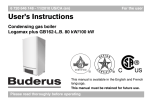
5645 469 8/97
Service Manual
Ecomatic HS 2102
Save These Instructions !
SYSTEM OVERVIEW
1
Mounting Instructions
4
2
Program Overview
6
3
Key Code
7
4
Installation Entries
5
Relay Test
19
6
Testing the Manual Reset High Limit (STB)
20
7
LCD Test
21
8
Heating Curve Display
22
9
Version Number
23
10
Troubleshooting Procedures
24
11
Reset
25
This manual is for reference only. The manual does NOT purport to address all design,
installation and safety considerations. It is the responsibility of the user of this manual to
determine the applicability and safety of each individual application and ensure its
compliance with local building codes.
12
Sensor Curves
26-27
It is expected that the user/installer is a licensed heating contractor with knowledge of
accepted industry practices for the installation and maintenance of the equipment and
various applications of the equipment involved.
13
Wiring Diagrams
28-29
The Ecomatic HS2102 is a weather responsive control that is designed for residential
heating systems with a single type of radiation, such as fin tube baseboard, panel radiators,
or cast iron radiators. It can also be used to control and prioritize an indirect fired domestic
hot water tank.
The control provides the following features:
•
•
•
•
•
•
•
•
•
•
•
Boiler water temperature modulation based on outdoor temperature.
Domestic hot water priority.
7-day programmable clock.
Daytime and nighttime temperatures.
Room temperature compensation with optional BFC room sensor.
Manual override switches for emergency operation.
Freeze protection for heating system; constant circulation in nighttime below freeze
temperature.
Freeze protection for indirect hot water tanks; maintenance tank at a minimum of
50°F (10°C) in night mode.
Malfunction display for system troubleshooting.
Standard non-adjustable 100°F/104°F pump logic for condensate protection of the boiler.
Pump kick during vacation and summer operation; the control will operate pumps for
1 minute at 12:00PM every Wednesday to prevent pump seizure.
The “Service Manual - Ecomatic HS 2102” will include all information necessary to mount, wire, and
place the Ecomatic control into operation. The settings described in this manual are intended for use by the
heating contractor.
To change settings such as the time, date and heating program, please refer to the “Operating Instructions Control panel HS 2102” . This manual will allow the homeowner to customize the control to their needs.
NOTE:
2
TABLE OF CONTENTS
8-18
3
1
Mounting Instructions
Mounting Instructions
1
Electrical connections must be made according to
the wiring diagram (See pages 28-31).
Remove the front panel of the boiler.
• Only necessary with G124X and G224
All the wires should be routed through the cable
raceway at the rear of the boiler. Rear panel jacket
may be modified per local code.
Remove the two screws and housing from the top of
the Ecomatic.
Insert the two front feet of the control
into the holes provided on the top of the
boiler. Then, firmly push down on the
rear of the control until it snaps into place.
Use the white strain reliefs provided to lock all cables
into place on the back of the control.
Fasten the control to the boiler jacket
using the two screws as shown.
The sensor bundle consists of one thermistor (FK), two
capillaries and a spacer. Mount the sensors per the following
boiler specific instructions.
Tilt the display to the desired position.
G115, G205, G305: Replace brass well with chrome
Ecomatic well. The sensor bundle should be inserted
into the Ecomatic well.
G124X: Unwrap the sensor bundle. Remove spacers from
the chrome well on the boiler. The high limit (STB) capillary
and temperature sensor (FK) should be inserted into the
chrome well with existing Honeywell Aquastat. The
remaining capillary should be mounted to the supply
manifold and thoroughly insulated.
G224: The tridicator assembly should be moved to the
supply piping and replaced with the chrome plated Ecomatic
well. The sensor bundle should be inserted into this well.
4
Replace the top housing of the control and fasten
the two screws. The control is ready to be placed
into operation.
5
1
Mounting Instructions
Mounting Instructions
1
Electrical connections must be made according to
the wiring diagram (See pages 28-31).
Remove the front panel of the boiler.
• Only necessary with G124X and G224
All the wires should be routed through the cable
raceway at the rear of the boiler. Rear panel jacket
may be modified per local code.
Remove the two screws and housing from the top of
the Ecomatic.
Insert the two front feet of the control
into the holes provided on the top of the
boiler. Then, firmly push down on the
rear of the control until it snaps into place.
Use the white strain reliefs provided to lock all cables
into place on the back of the control.
Fasten the control to the boiler jacket
using the two screws as shown.
The sensor bundle consists of one thermistor (FK), two
capillaries and a spacer. Mount the sensors per the following
boiler specific instructions.
Tilt the display to the desired position.
G115, G205, G305: Replace brass well with chrome
Ecomatic well. The sensor bundle should be inserted
into the Ecomatic well.
G124X: Unwrap the sensor bundle. Remove spacers from
the chrome well on the boiler. The high limit (STB) capillary
and temperature sensor (FK) should be inserted into the
chrome well with existing Honeywell Aquastat. The
remaining capillary should be mounted to the supply
manifold and thoroughly insulated.
G224: The tridicator assembly should be moved to the
supply piping and replaced with the chrome plated Ecomatic
well. The sensor bundle should be inserted into this well.
4
Replace the top housing of the control and fasten
the two screws. The control is ready to be placed
into operation.
5
2
Program Overview
Key Code
3
Possible settings for the installation level.
The following settings allow the heating contractor to
customize the Ecomatic HS 2102 control for the
particular application.
1.
Language:
Factory Setting: American
Other Languages: Deutsch, English,
Español, Italiano, etc.
2. Temperature Scale:
Factory Setting: Fahrenheit
Optional Selection: Celsius
3.
Heating curve-REF TEMP:
Factory Setting: 167°F (75˚ C)
Range: 122°F to 194°F (50°C to 90°C)
4.
Freeze protection temperature-FREEZTEMP:
Factory Setting: 34°F (1°C)
Range: 14°F to 50°F (-10°C to 10°C)
10. Flue Gas Sensor-FLUE GAS:
Factory Setting: Off
(Not available in the USA)
The access to the installation level is protected against
unauthorized use by a key code. This will enable you
to change settings described in this manual.
11. Clock recalibration-TIM ADJ:
Factory Setting: 0 Sec/Day
Range: -59 to 59 Sec/Day
This operating level should only be accessed by a
heating contractor or a trained operator.
12. Room temperature shift-OFFSET:
Factory Setting: 0
Range: -9°F to 9°F (-5°C to 5°C)
Accessing the installation level.
13. Diagnostic Test Features:
Relay Test
LCD Test
Heating curve display
Version number
Key Code
• Press and release the “AUT” button. Button
is located adjacent to cover flap.
5.
Room Sensor - BFC:
Factory Setting: Off
Option: On
• Press and hold down the “INS”
button.
6.
Compensation temperature-ROOM COMP:
(only with room sensor)
Factory Setting: 5°F (3°C)
Range: 0°F to 18°F (0°C to 10°C)
• Insert a pointed object into the hole
to the right of the “INS” button. Release
the “INS” button and remove the pointed
object from the hole.
Setback modes:
Factory Setting: Outside Air Setback
Options:
Setback
Room Setback
Boiler Off
• The control automatically
reverts back to previous operation if no
entries are made within 20 seconds.
7.
6
Key Code
8.
Minimum boiler water temperature-MIN TEMP:
Factory Setting: 50°F (10°C)
Range: 50°F to 104°F (10°C to 40°C)
9.
Maximum boiler water temperature-MAX TEMP:
Factory Setting: 185°F (85°C)
Range: 149°F to 194°F (65°C to 90°)
INS
O
• Different settings become accessible
by repeatedly pressing the “INS” button.
The display will indicate the current
setting. The value of each setting is
changed by turning the dial.
SETTING THE LANGUAGE TO AMERICAN
•
•
•
Enter the key code
Turn dial until “American” appears.
Automatic operation is resumed after
20 seconds.
AMERICAN
7
4
Installation Entries
Installation Entries
4
Reference Temperature - Heating Cur ve Selection
The heating curve establishes the relationship between
the outside air and boiler water temperatures. The boiler
water temperature is lowered at warmer outside air
temperatures and the boiler water temperature is raised at
colder outside air temperatures.
The correct heating curve is determined by the
characteristics of the house, (ie. type of radiation,
construction, degree of insulation, etc.). Baseboard
systems are generally operated at 194°F at the outside
design temperature. Several curves are shown for
different design temperatures. Follow the curve to the
14°F outside temperature. Read the corresponding
boiler water temperature on the vertical scale. This is
your REF TEMP setting.
The control automatically creates a curve for all outside
temperatures. The factory setting for REF TEMP is 167°F.
To adjust the heating curve, raise or lower the REF TEMP
value on the control.
This setting is an approximation based on design
conditions and may need adjustment after the system
has been operating for some time.
REF TEMP
Setting the REF TEMP.
˚F
167
The heating curve is adjusted when the reference
temperature is changed.
The factory setting is 167˚ F; range is 122°F to 194°F.
BOILER
WATER
TEMPERATURE (°F)
0
194
-10
-20
-30
-40
176
167
158
Procedure
1. Enter the key code.
140
2. Press the “INS” button repeatedly until “REF TEMP”
appears in the display.
122
104
3. Turn the knob until the desired “REF TEMP” appears.
86
68
68
59
50
41
32
23
14
5
-4
-13
-22 -31
OUTSIDE TEMPERATURE (°F)
-40
Automatic operation is resumed after 20 seconds.
REF TEMP
˚F
167
Heating cur ve adjustments:
The REF TEMP fine adjustment should be done based on cold
weather performance. Increase the REF TEMP value if the room
temperature is too low during the cold days. Decrease the REF
TEMP if overheating tends to occur at low outside temperatures.
Make only minor adjustments and allow ample time for system
to respond. For fine adjustment of the curve during mild
weather, please consult page 18.
Example:
REF TEMP Selection
Assume the maximum design water temperature for a
panel radiator system is 176°F. The curve shown is based
on a -20°F design temperature. To select this curve, set
the REF TEMP value to 140°F. The control then creates
this heating curve automatically.
194
176
158
140
122
104
86
68
68
52
36
20 14 4
-12 -20 -28
-44
OUTSIDE TEMPERATURE (°F)
8
9
4
Installation Entries
Installation Entries
4
Reference Temperature - Heating Cur ve Selection
The heating curve establishes the relationship between
the outside air and boiler water temperatures. The boiler
water temperature is lowered at warmer outside air
temperatures and the boiler water temperature is raised at
colder outside air temperatures.
The correct heating curve is determined by the
characteristics of the house, (ie. type of radiation,
construction, degree of insulation, etc.). Baseboard
systems are generally operated at 194°F at the outside
design temperature. Several curves are shown for
different design temperatures. Follow the curve to the
14°F outside temperature. Read the corresponding
boiler water temperature on the vertical scale. This is
your REF TEMP setting.
The control automatically creates a curve for all outside
temperatures. The factory setting for REF TEMP is 167°F.
To adjust the heating curve, raise or lower the REF TEMP
value on the control.
This setting is an approximation based on design
conditions and may need adjustment after the system
has been operating for some time.
REF TEMP
Setting the REF TEMP.
˚F
167
The heating curve is adjusted when the reference
temperature is changed.
The factory setting is 167˚ F; range is 122°F to 194°F.
BOILER
WATER
TEMPERATURE (°F)
0
194
-10
-20
-30
-40
176
167
158
Procedure
1. Enter the key code.
140
2. Press the “INS” button repeatedly until “REF TEMP”
appears in the display.
122
104
3. Turn the knob until the desired “REF TEMP” appears.
86
68
68
59
50
41
32
23
14
5
-4
-13
-22 -31
OUTSIDE TEMPERATURE (°F)
-40
Automatic operation is resumed after 20 seconds.
REF TEMP
˚F
167
Heating cur ve adjustments:
The REF TEMP fine adjustment should be done based on cold
weather performance. Increase the REF TEMP value if the room
temperature is too low during the cold days. Decrease the REF
TEMP if overheating tends to occur at low outside temperatures.
Make only minor adjustments and allow ample time for system
to respond. For fine adjustment of the curve during mild
weather, please consult page 18.
Example:
REF TEMP Selection
Assume the maximum design water temperature for a
panel radiator system is 176°F. The curve shown is based
on a -20°F design temperature. To select this curve, set
the REF TEMP value to 140°F. The control then creates
this heating curve automatically.
194
176
158
140
122
104
86
68
68
52
36
20 14 4
-12 -20 -28
-44
OUTSIDE TEMPERATURE (°F)
8
9
4 Installation Entries
Installation Entries
Setting the FREEZTEMP.
BFC Room Sensor:
To prevent the heating system from freezing in the setback
heating mode, the control will automatically run the heating
circulator when the outdoor temperature drops below the
set value.
To change the FREEZTEMP:
The BFC room sensor is an optional room thermostat
that allows you to set and adjust day and night time
temperatures at the BFC. The BFC allows the control to
fine tune the boiler water temperature based on the desired
room temperature and the current room temperature. For
each degree of room temperature deviation from the BFC
setting, the BFC and the control adjust the boiler water
temperature by 3°. The BFC allows you to manually override
your heating program. If a BFC is not used, the control
operates using only outside temperature as a reference.
1. Enter the key code.
The BFC room sensor selection must be activated if the
system is equipped with a BFC.
2. Press the “INS” button repeatedly
until “FREEZTEMP” appears in the display.
To activate the BFC
The factory setting is 34˚ F; range is 14°F to 50°F.
3. Turn the knob until the desired “FREEZTEMP” appears
in the display.
Automatic operation is resumed after 20 seconds.
FREEZTEMP
˚F
34
4
1. Enter the key code.
2. Press the “INS” button repeatedly until “BFC” appears
in the display.
3. Turn the knob until “ON” appears in the display.
BFC
ON
Automatic operation is resumed after 20 seconds.
Once the BFC room sensor has been activated, it is
no longer possible to adjust the day and night time
temperatures on the control panel; they can only be
adjusted at the BFC room sensor.
10
11
4
Installation Entries
Installation Entries
4
Setback Mode
Changing the ROOM COMP:
(Room temperature compensation)
The control allows you to choose a lower nighttime, setback temperature.
You can choose from one of the following four modes
for night setback.
The BFC room sensor compensates for swings in room temperature,
(ie: solar gain, open windows, etc.). The amount of compensation
can be adjusted according to individual preference.
1.
2.
3.
4.
The room temperature compensation range can only be changed if
a BFC room sensor has been activated.
Outside Air Setback - OASETBACK (Factory Setting)
Setback - SETBACK
Boiler Off - BLR OFF
Room Setback - RMSETBACK
OASETBACK
Selecting the setback mode
Example:
OASETBACK: If the outside temperature is below the FREEZTEMP,
(FREEZTEMP was set on page 10), boiler runs on a
setback curve.
With the ‘ROOM COMP” at OFF, the BFC room
sensor will have no effect on the boiler water
temperature.
The amount of room temperature change that the
control compensates for is adjustable. With the
“ROOM COMP” at 15˚ F, the BFC will be able to
adjust to a 15˚ F (+10/-5) swing in room
temperature by adjusting boiler water temperature
accordingly.
The factory setting is 5˚ F; range is 0°F to 18°F.
ROOM COMP
˚F
If the outside temperature is above the FREEZTEMP,
heating system is off.
SETBACK:
5
BLR OFF:
The boiler is set to the lower nighttime temperature. Set
directly with temperature button on control panel. This
mode is only to be used when no BFC is connected. The
pump runs continuously based on the nighttime room
temperature.
The heating circuit is completely switched off during
setback times, except when the outside temperature is
below the FREEZTEMP, then the system runs on a
setback curve.
To change the “ROOM COMP”:
RMSETBACK: The nighttime room temperature is set with the slide
switch on the BFC room sensor. This mode requires
the use of the BFC.
1. Enter the key code.
Recommended Settings:
2. Press the “INS” button repeatedly until “ROOM COMP”
appears in the display.
3. Turn the knob until “OFF”, or the desired temperature
appears in the display.
Automatic operation is resumed after 20 seconds.
SETBACK
BLR OFF
Heating system with BFC
room sensor:
RMSETBACK
Heating system without
BFC room sensor:
SETBACK
Commercial buildings without
BFC room sensor:
SETBACK
Non-occupied in night mode:
OASETBACK
Heating zone completely switched off,
except for freeze protection:
BLR OFF
RMSETBACK
To change the setback mode:
1. Enter the key code.
2. Press the “INS” button repeatedly until ‘OASETBACK’ appears in the
display.
3. Turn the knob until the desired setback mode appears.
12
Automatic operation is resumed after 20 seconds.
13
4
Installation Entries
Installation Entries
4
Setback Mode
Changing the ROOM COMP:
(Room temperature compensation)
The control allows you to choose a lower nighttime, setback temperature.
You can choose from one of the following four modes
for night setback.
The BFC room sensor compensates for swings in room temperature,
(ie: solar gain, open windows, etc.). The amount of compensation
can be adjusted according to individual preference.
1.
2.
3.
4.
The room temperature compensation range can only be changed if
a BFC room sensor has been activated.
Outside Air Setback - OASETBACK (Factory Setting)
Setback - SETBACK
Boiler Off - BLR OFF
Room Setback - RMSETBACK
OASETBACK
Selecting the setback mode
Example:
OASETBACK: If the outside temperature is below the FREEZTEMP,
(FREEZTEMP was set on page 10), boiler runs on a
setback curve.
With the ‘ROOM COMP” at OFF, the BFC room
sensor will have no effect on the boiler water
temperature.
The amount of room temperature change that the
control compensates for is adjustable. With the
“ROOM COMP” at 15˚ F, the BFC will be able to
adjust to a 15˚ F (+10/-5) swing in room
temperature by adjusting boiler water temperature
accordingly.
The factory setting is 5˚ F; range is 0°F to 18°F.
ROOM COMP
˚F
If the outside temperature is above the FREEZTEMP,
heating system is off.
SETBACK:
5
BLR OFF:
The boiler is set to the lower nighttime temperature. Set
directly with temperature button on control panel. This
mode is only to be used when no BFC is connected. The
pump runs continuously based on the nighttime room
temperature.
The heating circuit is completely switched off during
setback times, except when the outside temperature is
below the FREEZTEMP, then the system runs on a
setback curve.
To change the “ROOM COMP”:
RMSETBACK: The nighttime room temperature is set with the slide
switch on the BFC room sensor. This mode requires
the use of the BFC.
1. Enter the key code.
Recommended Settings:
2. Press the “INS” button repeatedly until “ROOM COMP”
appears in the display.
3. Turn the knob until “OFF”, or the desired temperature
appears in the display.
Automatic operation is resumed after 20 seconds.
SETBACK
BLR OFF
Heating system with BFC
room sensor:
RMSETBACK
Heating system without
BFC room sensor:
SETBACK
Commercial buildings without
BFC room sensor:
SETBACK
Non-occupied in night mode:
OASETBACK
Heating zone completely switched off,
except for freeze protection:
BLR OFF
RMSETBACK
To change the setback mode:
1. Enter the key code.
2. Press the “INS” button repeatedly until ‘OASETBACK’ appears in the
display.
3. Turn the knob until the desired setback mode appears.
12
Automatic operation is resumed after 20 seconds.
13
Installation Entries
4 Installation Entries
MIN TEMP:
4
MAX TEMP:
The control can be set to maintain a minimum boiler water
temperature during the heating mode. This is the ‘MIN TEMP”.
The control can be set not to exceed a maximum boiler
water temperature.
The boiler will not fall below the “MIN TEMP” during the
heating mode.
The boiler water will not exceed the “MAX TEMP”.
The factory setting is 50˚ F; range is 50°F to 104*F.
The factory setting is 185˚ F; range is 167°F to 194°F.
To change the “MIN TEMP”:
To change the ‘MAX TEMP’:
1. Enter the key code.
2. Press the “INS” button repeatedly until “MIN TEMP”
appears in the display.
3. Turn the knob until the desired minimum boiler
temperature appears.
Automatic operation is resumed after 20 seconds.
1. Enter the key code.
MIN TEMP
˚F
50
2. Press the “INS” button repeatedly until “MAX TEMP”
appears in the display.
MAX TEMP
˚F
185
3. Turn the knob until the desired maximum
temperature appears in the display. The control will
never exceed this maximum value except during
the burner relay test as described in the Manual
Reset High Limit Test.
Automatic operation is resumed after 20 seconds.
Every time the burner fires, the boiler water will reach
at least 113˚ F to ensure that the flue way passages remain
dry. This value cannot be changed.
14
15
4
Installation Entries
Installation Entries
4
Clock
Flue Gas
The time clock can be adjusted if the clock runs too fast
or too slow with the ‘TIM ADJ”.
The flue gas temperature can only be measured with an
additional module, not available in the United States.
The factory setting is “OFF”. This must remain in the off
position or an error message will appear.
For example: If the clock runs 10 seconds too fast per day,
set the TIME ADJ to -10.
Range is -59 to +59 sec/day.
FLUE GAS
OFF
To change the “TIM ADJ”:
1. Enter the key code.
2. Press the “INS” button repeatedly until ‘TIM ADJ”
appears in the display.
TIM ADJ
0
3. Turn the knob until the desired time
adjustment appears in the display.
Automatic operation is resumed after 20 seconds.
16
17
4
Installation Entries
Installation Entries
4
Clock
Flue Gas
The time clock can be adjusted if the clock runs too fast
or too slow with the ‘TIM ADJ”.
The flue gas temperature can only be measured with an
additional module, not available in the United States.
The factory setting is “OFF”. This must remain in the off
position or an error message will appear.
For example: If the clock runs 10 seconds too fast per day,
set the TIME ADJ to -10.
Range is -59 to +59 sec/day.
FLUE GAS
OFF
To change the “TIM ADJ”:
1. Enter the key code.
2. Press the “INS” button repeatedly until ‘TIM ADJ”
appears in the display.
TIM ADJ
0
3. Turn the knob until the desired time
adjustment appears in the display.
Automatic operation is resumed after 20 seconds.
16
17
4 Installation Entries
Relay Test
5
Relay Test
OFFSET
You can use the relay test to test the switch relays in
the control panel. The following relays can be tested.
The “OFFSET” can be used when the actual room
temperature differs from the room temperature setting.
The “OFFSET” will raise or lower the room temperature
the amount of degrees set. The “OFFSET” performs a
parallel vertical shift to the heating curve. A 1°adjustment
for the “OFFSET” will result in a 3° adjustment in boiler
water temperature.
• Burner
• Domestic hot water circulator
• Heating circulator
RELAY
To test the relays:
Heating cur ve adjustments:
If the room temperature is too low/high for all outside
temperatures, increase/decrease the “OFFSET”.
1. Enter the key code.
If the room temperature is too low only during moderate outside
temperatures, increase the “OFFSET” and decrease the “REF
TEMP” slightly. Make only small adjustments and allow ample
time for the system to respond.
2. Press the “INS” button repeatedly until “RELAY” appears in
the display. The actual system status is shown in the
display.
To change the “OFFSET”:
OFFSET
˚F
0.0
1. Enter the key code.
2. Press the “INS” button repeatedly until “OFFSET”
appears in the display.
3. Turn the knob until the desired offset appears in
the display.
RELAY
3. Turn the knob. The flame symbol for the burner appears
first. The burner will come on at this point.
4. Turn the knob further. The symbols for the domestic hot
water circulator and heating circulator will appear and
start up the respective circulators.
RELAY
The test has no time limit. To stop the test, press the
“INS” or “AUT” button.
Automatic operation is resumed after 20 seconds.
Example:
Desired room temperature: 65˚ F
Actual room temperature: 63˚ F
The “OFFSET” should be 2.0˚ F
18
19
6
Testing the Manual Reset High Limit (STB)
LCD Test
7
RELAY
Figure 1.
1.
Switch the control on
with the main power
switch (I Button).
2.
Enter the key code
(See page 7)
LCD Test:
You can use the LCD Test to check whether all digits
and symbols are shown properly in their display.
RELAY
3.
Press the INS repeatedly until “RELAY”
appears in the display (See Fig. 1).
4.
Turn the knob until the flame symbol
for the burner relay appears. The burner
will come on (See Fig. 2).
Heating pumps will not run during the
burner test. Allow the burner to run
until burner shuts off at the setpoint
on the aquastat dial.
5.
6.
7.
Remove the black aquastat dial.
(See Fig. 3)
Push the green button in with a
screwdriver or similar instrument to
bypass the adjustable boiler aquastat.
Hold the green button until the STB,
manual reset high limit trips. This
happens at approximately 230°F
(See Fig. 4).
1. Enter the key code.
Figure 2.
2. Press the “INS” button repeatedly until
“LCD TEST” appears in the display.
3. Turn the knob. All digits and symbols must
appear correctly in the display. The display
is defective if it is not complete, and should
be replaced.
Automatic operation is resumed after
20 seconds.
C
Figure 3.
180
Aquastat Dial
Green Button
Figure 4.
Run circulators to remove excess heat.
Then, to reset the STB, remove the
safety nut (See Fig. 5). Press in the reset
button underneath. This will return the
control back to normal operation.
C
To Resume Normal Operation:
Figure 5.
Press the INS button or AUT button.
Safety Nut
20
21
8
Version Number
Heating Curve Display
9
Version Number
Heating Cur ve Display
You can use the heating curve test to display
the heating water temperature at three different
outdoor temperatures; 50˚ F, 32˚ F, 14˚ F.
The version number is a manufacturer’s number
and represents the settings of the control.
It must be specified when goods are being
returned for possible defects.
ATTENTION:
To view the version number:
Values can not be changed in this screen, only displayed.
HTG CURVE
To view the “HTG CURVE”:
131
˚F
50
1. Enter the key code.
2. Press the “INS” button repeatedly until
“VERSION” appears in the display.
VERSION
1. Enter the key code.
2. Press the “INS” button repeatedly until the
“HTG CURVE” appears in the display.
3. Turn the knob. The first display shows the heating
water temperature for 50˚ F, the second for 32˚ F, the
the third for 14˚ F, mark these three water temperatures
in the figure on page 8 for future reference.
4. Automatic operation is resumed after 20 seconds.
22
HTG CURVE
150
HTG CURVE
167
˚F
32
Automatic operation is resumed after 20 seconds.
106
4
˚F
14
23
Reset
10 Troubleshooting Procedures
The Ecomatic HS 2102 reports the following service messages as part of its self-diagnostic capability.
Reset
Message (ERR)
Meaning
Action
1. Press and hold down the Time, Insert and
Cancel buttons simultaneously until “RESET”
appears in the display.
BURNER
Burner lock-out
Check burner and press burner reset.
BOIL SENS
Defective FK sensor
Check resistance of FK sensor and
verify with curve.
OA SENSOR
Defective outside air sensor
Check resistance of OA sensor and
verify with curve.
DHW SENS
Defective DHW sensor
Check resistance of BF sensor and
verify with curve.
HEATING
Heating system stays cold.
Continued pump logic operation.
Turn control OFF/ON.
Check boiler operation.
DHW
DHW stays cold for 2 hours.
Check tank pump operation.
BFC
BFC does not respond
Check wiring to BFC.
INTERNAL
Internal error
Turn control OFF/ON. Electronic
module may need to be replaced.
Contact Buderus Hydronic Systems.
These messages are very helpful in troubleshooting the Ecomatic HS 2102. Consult the sensor curves
to verify proper sensor operation. In case of sensor failure, the HS 2102 continues burner and circulator
operation to prevent possible freeze-up of the heating system.
24
11
2. Keep all three buttons depressed until all
characters have disappeared from the display.
This resets all key settings back to the factory
settings, language to “AMERICAN”, and unit
of temperature to Fahrenheit.
The heating program, time and day of the week
remain the same.
INS
O
RESET
88 88
88 8
25
Reset
10 Troubleshooting Procedures
The Ecomatic HS 2102 reports the following service messages as part of its self-diagnostic capability.
Reset
Message (ERR)
Meaning
Action
1. Press and hold down the Time, Insert and
Cancel buttons simultaneously until “RESET”
appears in the display.
BURNER
Burner lock-out
Check burner and press burner reset.
BOIL SENS
Defective FK sensor
Check resistance of FK sensor and
verify with curve.
OA SENSOR
Defective outside air sensor
Check resistance of OA sensor and
verify with curve.
DHW SENS
Defective DHW sensor
Check resistance of BF sensor and
verify with curve.
HEATING
Heating system stays cold.
Continued pump logic operation.
Turn control OFF/ON.
Check boiler operation.
DHW
DHW stays cold for 2 hours.
Check tank pump operation.
BFC
BFC does not respond
Check wiring to BFC.
INTERNAL
Internal error
Turn control OFF/ON. Electronic
module may need to be replaced.
Contact Buderus Hydronic Systems.
These messages are very helpful in troubleshooting the Ecomatic HS 2102. Consult the sensor curves
to verify proper sensor operation. In case of sensor failure, the HS 2102 continues burner and circulator
operation to prevent possible freeze-up of the heating system.
24
11
2. Keep all three buttons depressed until all
characters have disappeared from the display.
This resets all key settings back to the factory
settings, language to “AMERICAN”, and unit
of temperature to Fahrenheit.
The heating program, time and day of the week
remain the same.
INS
O
RESET
88 88
88 8
25
Sensor Curves
12 Sensor Curves (General)
Switch the power off before taking any measurements. Remove sensors from the back of the Ecomatic and measure
the resistance of the cable ends. The curves show mean values and are subject to deviations.
12
Room Temperature Sensor (BF)
Outdoor temperature sensor (FA)
41
5
32
23
14
59
50
41
50
59
68
77
86
Room Temperature (°F)
Outdoor Temperature (˚F)
Boiler, domestic hot water temperature sensors (FK, FB)
68
86
104
122
140
158
176
194
Boiler Water Temperature (˚F)
26
27
13 Wiring Diagrams
28
Wiring Diagrams
13
29
13 Wiring Diagrams
28
Wiring Diagrams
13
29
13 Wiring Diagrams
30
Boiler installed by:
(contractor’s address)
Boiler installed on:
(date of installation)
Buderus Hydronic Systems
50 Wentworth Avenue
Londonderry, NH 03053 USA
Tel: (603) 552-1100 • Fax: (603) 421-2719
www.buderus.net
Buderus Hydronic Systems, Inc. reserves the right to make changes without notice due to continuing
engineering and technological advances.