1
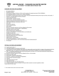
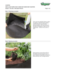
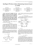
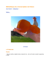
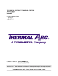
Solar Autoclave for Rural Areas
By:
Blake Lawrence, Eric Brettner, Yuchen Liu, Kyle Godwin,
and Adam Compton
Team 6
Final Report
Document
Submitted towards partial fulfillment of the requirements for
Mechanical Engineering Design – Spring 2013
Department of Mechanical Engineering
Northern Arizona University
Flagstaff, AZ 86011
Table of Contents
Abstract............................................................................................................................................3 Problem Statement.......................................................................................................................4 Objectives ....................................................................................................................................4 Constraints ...................................................................................................................................5 Thermal Capture ..........................................................................................................................6 Insulation .....................................................................................................................................7 Methods ...........................................................................................................................................8 Thermal Circuit..........................................................................................................................11 Final Design...................................................................................................................................13 Manufacturing ...............................................................................................................................14 Boiler .........................................................................................................................................14 Parabolic Trough .......................................................................................................................17 Pressure Vessel ..........................................................................................................................19 Homemade Pressure Vessel.......................................................................................................22 Cost Analysis.................................................................................................................................24 User Interface ................................................................................................................................25 Conclusion .....................................................................................................................................26 References .....................................................................................................................................28 Appendices ....................................................................................................................................29 Appendix A................................................................................................................................30 Appendix B................................................................................................................................34 Abstract
An autoclave is a device used to sterilize medical equipment. While there are many sterilization
techniques available, the preferred method for this project is steam sterilization. In this process,
water is pressurized to raise its boiling point. When this occurs, steam will be created at a
temperature higher than 100oC. In fact, in order to fully eliminate all prions and bacteria
associated with disease, saturated steam needs to be at least 121oC when in contact with the
equipment being sterilized. Currently, many advanced designs are being used in western
countries. These designs are usually powered with electricity and use computers to monitor the
internal temperatures and pressures. Unfortunately, many developing areas around the world do
not have the technology available to operate these types of autoclaves. As a result, nurses and
doctors at remote health clinics in these rural areas are continually challenged with the decision
to operate with unsanitary equipment, risking the spread of infection, or to not operate at all. A
solar autoclave provides an alternative solution to this problem. Using only solar radiation, a
solar autoclave can provide remote health clinics with an inexpensive, efficient way to sterilize
medical equipment.
Our design was fabricated to be strong, reliable, and cost efficient. The solar autoclave testing
was generally successful reaching just shy of our goal temperature. This was caused by heat loss.
The final numbers during testing were 1.2 bar (gauge) and a temperature of 118oC.
Solar Autoclave for Rural Areas Page 3 Figure 1 – Solar Autoclave for Rural Areas
Introduction
Problem Statement
Many developing areas around the world have limited availability to sterilized medical
equipment. Currently, several countries in rural areas cannot properly sterilize what limited
medical equipment is available. This results in medical treatment or surgery with unsafe
equipment, risking the chance of infection and possibly the life of the patient. Sometimes, no
treatment is done at all. This need is located across the globe, but for this project the location of
focus will be Central Africa. This region was chosen based off of the lack of resources and
abundant sunlight.
•
•
Overall Goal Statement – To create a solar autoclave that can be easily used at remote
clinics in rural areas.
Overall Scope of Goal – The project will be aimed for several regions across the globe in
need of sterile medical equipment, with ample amounts of sunlight to power the solar
autoclave.
Objectives
The three main objectives for this project include:
•
•
To provide remote clinics in rural areas with the means to sterilize medical equipment.
To create a flexible design from location to location.
Solar Autoclave for Rural Areas Page 4 •
o A solar autoclave can be implemented in any region with enough sunlight
available. This design will be able to me modified using the resources and
materials locally available.
The individual parts can be repaired or replaced from local, readily available materials.
Below is a table of the objectives listed along with the basis for measurement for each.
Table 1 – Table of Objectives
Constraints
There are not many constraints for this project. The most important one is to sterilize the
medical equipment. This constraint can be broken up into two categories: temperature and
pressure. These two sub constraints include:
•
•
Temperature of steam must reach and hold 121oC for at least 15 minutes.
Pressure must reach and hold 2.05 bar (absolute pressure) for at least 15 minutes.
Research
Different types of sterilization were considered. After learning about dry heat and steam
sterilization, the choice was clear. Both methods offer advantages and disadvantages, but steam
sterilization was determined to be the dominant method. The pros and cons for dry sterilization
are listed below:
Pros:
•
•
Does not require water
Produces a lower gauge pressure, meaning the process is safer
Cons:
•
Takes 2 hours at 160°C to clean equipment
Solar Autoclave for Rural Areas Page 5 •
Does not fully sterilize medical equipment
o Does not kill all prions and proteins associated with bacteria
Although dry heat sterilization is safer to operate, it takes much longer than steam sterilization
and does not fully sterilize the medical equipment. Further research showed that saturated steam
sterilization requires a temperature of 121°C for only 15 minutes and fully sterilizes the medical
equipment; steam sterilization is the better method because the contact for heat transfer is more
efficient.
Different types of medical equipment that are in need of sterilization at these remote clinics
range from syringes to scalpels. A majority of the equipment are small handheld devices. This
medical equipment is used by doctors and nurses at these remote clinics. So operation of the
solar autoclave will need to be operated by doctors and nurses, but optimally by anyone.
Concept Research
The initial phase of the solar autoclave project included researching ideas for each of the major
component of our design. The main components include:
•
•
Thermal Capture
Insulation
Thermal Capture
For solar thermal capture, there are three main designs that are used for efficiently harnessing the
power of the sun. A parabolic trough, dish, and Fresnel lens all focus the radiation of the sun to a
single focal point. Focal points are different depending on the size and shape of the mirror or
lens. Having a mirror or lens with a larger area than the pressure vessel and focusing the energy
to a smaller point allows the system to reach and maintain the required temperature to superheat
the steam at 121˚C.
Parabolic troughs, shown in Figure 2, focus heat onto a long cylinder of fluid which lies parallel
to the trough at the focal point. These require a large area to operate. Parabolic dishes, shown in
Figure 3, use a circular mirror to focus the heat onto a container held at the focal point. These
are effective if used correctly and also require a large area. Both parabolic dishes and troughs can
be made from a mosaic of smaller mirrors, allowing them to be made cheaper than a single
mirror. Finally, a Fresnel lens uses concentric rings over a plastic lens. These rings are all
manufactured to focus light to one location: the focal point. Since the amount of heat and
radiation is intensified at this point, the rate of heat transfer is dramatically higher. This process
takes a larger surface area of thermal collection than our pressure vessel, and focuses the heat
onto that vessel, heating the system. Fresnel lenses, shown in Figure 4 can be found in rear
projection televisions. Usually made from plastic, these lenses are lighter, cheaper, and more
durable than mirrors. A downfall of lenses is that they act as a filter and can absorb some of the
energy. For this application, this may or may not be a factor. A major problem with Fresnel
Solar Autoclave for Rural Areas Page 6 lenses is their availability in remote countries. Locating one of these lenses or the flat panel
televisions they are removed from may be difficult, if not impossible. For the solar autoclave a
parabolic trough is easier to manufacture and the clear choice for the final design.
Figure 2 – Parabolic Trough
Figure 3 – Parabolic Dish
Figure 4 – Fresnel Lens
Insulation
Reaching 121 ˚C is the goal for obtaining sterility, but this temperature must be maintained for a
certain time span in order to guarantee every piece of equipment is clean and safe to use. Using
insulation can help to retain heat and minimize heat loss. The thin walls of the pressure vessel
and the hose are two crucial places where heat will try to escape. The boiler will be covered with
transparent plastic to help stop forced convection. The table below lists a variety of materials
with low thermal conductivity. Materials with a low thermal conductivity will maximize the
thermal resistance preventing heat loss.
Solar Autoclave for Rural Areas Page 7 Table 2 – Thermal Conductivity [k] of Insulation Materials
Thermablok Aerogel is clearly the best choice, but unfortunately Thermablok Aerogel is very
expensive and hard to obtain. It was developed by NASA and is currently the most efficient
insulation material on the market. Unfortunately, it would be almost impossible to obtain in a
developing or rural area. The next best material for insulation was chosen as Styrofoam for the
hose and fiberglass for the pressure vessel, which has both a lower thermal conductivity than
other materials and is readily available. Both Styrofoam and fiberglass were considered to be
readily available because of its common use.
Methods
= ∙( 2− 1)
(1)
Where:
E = Energy, in kJ
m = Mass of water, in kg
u = Internal energy, in
For the solar autoclave to properly sterilize the medical equipment, the temperature of the steam
will need to be brought from room temperature (20 C) to 121 C. After using Shapiro’s
Fundamentals of Engineering Thermodynamics [1], the internal energy values at room
temperature and 121°C can be found as shown in the table below. Based on these values and
Equation 1 above, the energy, or heat transfer value can then be determined once the mass of
water is known. The boiler will use 2 liters of water to fill a larger pressure vessel with steam.
At room temperature, 2 liters of water equates to 2 kilograms. Therefore, the mass of water in
the system will be approximately 2 kilograms within the boiler.
Solar Autoclave for Rural Areas Page 8 Table 3 – Thermodynamic Properties for Saturated Liquid
Using Equation 1 above, the energy required to heat the water in the autoclave is found to be
847,604 Joules. Once the energy has been transferred to the water within the boiler the steam
then slowly fills up the hose and pressure vessel to evacuate the air. Once fully filled with steam,
the pressure vessel will be closed using the ball valve on the bottom of the vessel. At this point,
the pressure will begin to rise and eventually overcome the pressure regulator system located on
the pressure vessel. The pressure regulator system monitors and regulates pressure so the system
will never go over the projected pressure.
Thermal Capture
Thermal capture is determined from the radiation being emitted from the sun. Applying the
equations from above, the projected area needed to acquire the necessary power is found from
Equation 2 below:
= · · ·
(2)
Where:
= the incoming power of the sun, in W
= the absorptivity of the bottom of the pressure vessel
= the reflectivity of the material on parabolic trough
= the solar irradiance, in
2
= the projected area from the trough, in 2
This equation can then be manipulated to solve for the projected area, shown in Equation 3
below:
= · · · ·
(3)
Where:
E = the energy required to raise the water temperature, in J
t = the time allotted to reach goal temperature, in seconds
Solar Autoclave for Rural Areas Page 9 = the estimated efficiency of the trough
Emissivity is a significant factor in how efficient the solar autoclave can be. Emissivity, , is
equal to absorptivity, , and directly related to reflectivity, . Therefore, a lower emissivity
value results in a higher reflectivity value. For the parabolic trough to effectively collect solar
power, reflectivity is very important. Equation 4 below shows the correlation between the two:
=1−
(4)
Where:
= the emissivity constant
Table 4 below shows the different emissivity and resulting reflectivity values of various
materials being considered for the parabolic trough.
Table 4 – Material Emissivity and Reflectivity
The importance of reflectivity requires a reliable material which can be easily replaced. Mylar is
affordable, abundant, and lightweight. The absorptivity of black spray paint was found to be
0.95, which was then lowered to 0.9 in order to be conservative in calculations. The solar
irradiance constant is assumed to be 850 2, but may vary between regions. In addition, a half
hour of time was estimated to heat the required amount of water, which equates to 1,800
seconds. A 60% efficiency for the homemade trough was also estimated. Finally, Equation 3
from above is used to solve for the projected area of the parabolic trough.
= 847604 [ ]1800 .9.97(.6)(850 2)=1.06 2
Increasing the projected area will help to ensure the sterilization temperature is reached even if
the efficiency of the home made trough is less than 60% since the reflective surface will not be
perfect. This measurement is on a square meter basis, and can be used to solve for the required
dimensions for the trough. The trough will have a length 2 meters and width of 0.75 meters.
Solar Autoclave for Rural Areas Page 10 A parabolic trough functions by reflecting the solar irradiance to a point along the length of the
trough, or focal point. To optimize the power reflected by a parabolic trough, the boiler must be
placed at the proper location depending on shape and dimensions of the parabola. Using the
known length and width needed to obtain goal temperature as well as an arbitrary focal length of
0.15 meters, the depth of the trough can be found. Figure 5 below shows the variables of the
parabolic trough.
Figure 5 – The variables of the solar collector
Equation 5 can then be used to solve for the depth of the trough.
= 224
(5)
Where:
d = the depth of the trough, in m
D = the diameter, in m
f = the focal length, in m
Solving for the depth with the diameter and focal length stated above will be 0.234 meters.
Equation 6 below will then solve for the shape of the parabola of the trough.
= 24
(6)
Thermal Circuit
The thermal circuit in Figure 6 demonstrates the flow of heat through the system. Heat enters
the system at the letter Q, which stands for heat flow, and travels to the right. The heat flow then
comes to its first red circle, which stands for the temperature of the water inside of the boiler.
The heat continues to travel to the right through either of the remaining resistors to the last red
circle, the temperature of the atmosphere, the surrounding air around the autoclave.
Solar Autoclave for Rural Areas Page 11 Figure 6 – Temperature vs. Thermocouple Number for Aluminum
Solar Autoclave for Rural Areas Page 12 Final Design
The final design harnesses the power of the sun using a trough, shaped from sheet metal, to
collect the energy and focus that energy along a pipe or boiler. The reflectivity of the surface
facing the boiler is extremely important. To improve this, the surface will be lined with Mylar.
The boiler is exposed to the highest temperatures so corrosion is a large factor, especially when
water is a main component of this system. For these reasons, schedule 40 galvanized steel was
chosen for the material of the pipe because it is both strong and resists corrosion. A brass ball
valve, located at the top of the inclined boiler, allows safe pouring of the water and removing of
the excess water. Steam then passes through the hose to the secondary chamber containing the
medical equipment. The steam, being less dense than the air within the chamber, slowly pushes
the air out of the valve located at the bottom of the chamber. Evacuating the air creates a better
environment to sanitize the equipment. The valve should be closed once it begins discharging
steam. After the valve is closed, the pressure begins to rise and therefore the temperature. The
pressure and temperature will continue to raise in the boiler, and in turn the pressure vessel. This
process will continue for at least 15-30 minutes until the equipment is safe for medical purposes.
Figure 7 – Solar Autoclave Prototype Design in SolidWorks
As you can tell from Figure 7, the Solar Autoclave Prototype, nicknamed “Troughdor”, has
several parts that involve its working process. The water is placed in the boiler pipe, directly at
Solar Autoclave for Rural Areas Page 13 the focal point of the trough. The pipe is held in place by the ends of the trough, one at the
bottom and one at the top. The capped end of the pipe slides into place via a pocket at the end of
the trough design. Since this design is only a prototype, it was decided that a lowering and
raising mechanism was not necessary in this design. Therefore, the trough is positioned by
cinder blocks located at the bottom of the trough. However, mobility of the prototype is essential
at this stage. The prototype carries a ‘wheelbarrow’ design with two wheels hanging on the end
of the trough.
Manufacturing
Boiler
The boiler spans a long distance to absorb the heat so the best choice to achieve this is a piping
system. Piping also is safe, both for water corrosion and against the temperature and pressure.
The smallest factor of safety on the boiler system is 4. The boiler will be made from various
components. These are listed as follows from the bottom working the way to the top (picture
follows description).
Galvanized 1-1/4” NPT Female cap – this cap will seal the bottom end with a factor of safety of
20 and an upper temperature range of 176˚C.
Figure 8 – Female Galvanized Cap
Galvanized 1-1/2” X 10' NPT Male pipe – the pipe is the main body of the boiler that will be
collecting the energy and transferring the energy to the water to create the steam needed. This
component also has a factor of safety of 20 and an upper temperature range of 176˚C.
Figure 9 – Galvanized Pipe
Solar Autoclave for Rural Areas Page 14 Galvanized 1-1/2” X 1-1/2” X 3/4" Reducing Tee Fitting – with this fitting attached to the top of
the pipe it will allow two points of entry. The perpendicular, or top fitting will allow water to be
added to the system when beginning. The parallel fitting will allow the steam to travel down to
the pressure vessel. This component also has a factor of safety of 20 and an upper temperature
range of 176˚C.
Figure 10 – Female Galvanized Tee Fitting
Galvanized 1-1/2” Plug – this plug will allow the addition of water to the system with then safely
sealing the perpendicular section of the tee fitting. This component also has a factor of safety of
20 and an upper temperature range of 176˚C.
Figure 11 – Galvanized Plug
Brass NPT Ball Valve (Male to Female) 3/4" – attached to the parallel end of the tee fitting this
will allow (once the boiler is taken out of the sun) a shut off valve, so the sterilized medical
equipment can be safely removed. This attachment has a factor of safety of 16 and upper
temperature range of 185˚C.
Figure 12 – Brass NPT Ball Valve
Dixon Stainless Steel 316 3/4” NPT Male 3/4" Hose Barb – attached to the female end of the ball
valve this will allow a safe connection to the hose that travels to the pressure vessel. Attached
over the hose will be a hose clamp to ensure the hose does not come free during use.
Solar Autoclave for Rural Areas Page 15 Figure 13 – Hose Barb
Gates Durion Silicon Heater Hose inside Diameter 3/4” – the hose will travel from the boiler to
the pressure vessel providing steam. The hose has a working pressure of 3.5 bar and an upper
temperature range of 204˚C.
Figure 14 – Gates Durion Silicon Heater Hose
Instructions to build:
The galvanized piping was cut and tapped on site at Home Depot to the desired length. Next step
is to Teflon all threads to ensure water tight steal. Then attach the cap located at the bottom of
the shaft, secure tightly with a monkey wrench. Next, attach the reducing tee at the top and
secure tightly with a monkey wrench. Next is the ball valve and attached to that is the hose barb,
both attached to the 3/4” side of the reducing tee fitting. The square plug allows the water to be
poured into the system and must be tightened with a crescent wrench before starting the
application of the design. Finally the hose can be secured to the hose barb.
Solar Autoclave for Rural Areas Page 16 Parabolic Trough
The trough is the most crucial aspect of the solar autoclave. Without proper acquisition of
radiation from the sun, the autoclave will not harness enough energy to successfully heat up the
water inside the boiler to the appropriate temperature inside the pressure vessel. The trough is
built to precision with the following materials:
•
•
•
•
•
•
•
•
•
Sheet metal: Zinc 24 gauge (8ft x 4ft)
Particle board: 2 x 5/8” (8ft x 4ft)
Screws: 2.5” Zinc Plated (100 count)
Nails: 1.5” Galvanized roofing nails (100 count)
Spray adhesive: “3m super 77 16.75 f. oz. multi-purpose spray adhesive”
Mylar: “Viagrow 25ft Mylar 2mil reflective film”
Clear Plastic: 1/16” (8ft x 4ft)
Classic Dolly
Scrap Metal
Without the boiler and pressure vessel attached, the desired outcome for the parabolic trough is
modeled in Figure 15 using SolidWorks software.
Figure 15 – SolidWorks Model of Desired Parabolic Trough Shape
Using the assumed irradiance of the sun, the projected area of the trough is calculated earlier as
1.06 m2, we use the dimensions 2 meters long by 1 meter wide for the sheet metal. However, in
order to construct the trough to the desired shape, particle board was used and cut into shape so
that we could bolt down the sheet metal to the particle board by drilling holes through the sheet
metal. Four “ribs” were used in the making of the trough and at this point the trough appears as
Figure 16:
Solar Autoclave for Rural Areas Page 17 Figure 16 – Parabolic Trough during Construction
In order to hold the boiler in place, two rivets are placed into two pieces of particle board large
enough to sit at both ends of the trough. One end is left as it is, while the other end needs a
stopper for the boiler to sit at one end. The sides are then bolted onto the ribs and ends of the
trough using heavy duty screws, leaving the frame of the trough as it lies. At this point, all of the
particle board is sealed as to prevent any water damage to the frame.
Edges protectors were also used to prevent damage from occurring during transportation of the
trough, and weight was reduced significantly by cutting large rectangles out of the sides as not to
affect the structure of the trough. Finally, spray adhesive was applied to the sheet metal and
Mylar is carefully applied along the sheet metal in order to enhance the reflectivity of the solar
radiation reaching the boiler. All of these materials used are readily available, and the end result
is shown below in Figure 17.
Figure 17 – Completed Solar Autoclave
Solar Autoclave for Rural Areas Page 18 Pressure Vessel
Following the boiler, a high temperature and pressure silicone hose will transfer the steam into
the pressure vessel that holds the medical equipment. The pressure vessel that was used for
testing was a modified Mirro-Matic 394M 4 Qt. Pressure Cooker. This pressure cooker was
determined to act as the base of the pressure vessel unit when it was located at a local Goodwill.
This was convenient for testing, and even shows how common one of these devices is, meaning
it is possible to obtain in a developing country. The reason this pressure cooker was only used
for testing is because we want to prove that this entire design can be made with normal materials.
In other words, we want to show that a pressure vessel can be designed without using something
“pre-made”; with only using common pots and pans. The design for that homemade pressure
vessel will be more detailed in a later section.
Figure 18 – Mirro-Matic 394M 4 Quart Pressure Cooker
The materials required to complete this pressure vessel include:
•
•
•
•
•
•
•
•
Mirro 9898 Pressure Regulator
Honeywell TD-165 Tridicator
Dixon Stainless Steel 316 1/4” NPT Male 3/4” Hose Barb
3/4” x 1/2” Galvanized Hex Bushing
Apollo 1/2” Brass Ball Valve NPT Full-Port
1/2” Conduit Nipple
3/4” Locknut
2 Washers
Solar Autoclave for Rural Areas Page 19 Figure 19 – Honeywell TD165 Tridicator
Figure 20 – Modified Pressure Regulator
The steps for manufacturing the pressure vessel are listed below:
Lid Manufacturing
1.
2.
3.
Remove the burst disk from the lid of the pressure cooker and replace with Dixon
hose barb.
Drill 7/16 in. hole symmetric to the hose barb on opposite side of lid (mirror the hole
with hose barb, using the vent tube in the center as reference).
Tap drilled hole with 1/4” NPT tap and install tridicator.
Base Manufacturing
4.
5.
6.
7.
8.
Drill 29/32 in. hole in bottom center of pressure cooker.
Tap drilled hole with 3/4” NPT tap and install hex bushing.
Secure hex bushing with washers and 3/4” locknut.
Thread 1/2” conduit nipple into the hex bushing.
Thread ball valve onto the conduit nipple.
Figure 21 – Apollo 1/2” Brass Ball Valve
Solar Autoclave for Rural Areas Figure 22 – Dixon Stainless Steel Hose Barb
Page 20 Most pressure cookers use a pressure regulator that only reaches 15 psig. This is because most
recipes that are followed do not require higher pressures than 15 psig. However, in order to
reach and exceed the required temperature of 121°C, the pressure inside the pressure vessel
needs to reach at least 18 psig. Therefore, weight needed to be added to the pressure regulator.
Equation 7 was used to determine how much weight needed to be added:
=
(7)
Where:
P = Pressure, in [psi]
F = Force, in [lb]
A = Area, in [in2]
The first step was solving for the area of the pressure regulator that is in contact with the vent
tube. The pressure regulator was weighed using a scale, and was measured at 3.3 ounces. This
converted to 0.21 pounds, and was used for the force value. The value of pressure used was 15
psi, and the corresponding area that resulted from the equation was 0.014 square inches. Next,
this calculated area was used, along with 18 psi, to solve for the corresponding force. This force
resulted in 0.25 pounds. After subtracting the two force values, it was determined that
approximately 19 grams of additional weight needed to be added to the pressure regulator in
order to allow for 18 psig during operation. This weight was added using appropriate nuts and
bolts, creating the modified pressure regulator. These modifications can be seen in Figure 18
above. A picture of the pressure vessel after the modifications were made can be seen in Figure
23 below.
Figure 23 – Pressure Vessel after Modifications
Solar Autoclave for Rural Areas Page 21 Homemade Pressure Vessel
List of Materials:
1)
2)
3)
4)
5)
6)
7)
8)
9)
Stainless steel stockpot with lid
12 in. Bar Clamp
Sealant
Vent tube for regulator
Hose fitting
Tridicator
Valve
Nut
Washer
The homemade pressure vessel should be made by materials that are readily available in rural
areas. Thus, basic components will be considered in the design. The pressure vessel has a
designed working pressure of 15 psi and an inner temperature of 121°C.
The major three parts for the homemade pressure vessel are the pot, gasket, and clamp system.
The pot should be strong enough to hold the high pressure without deforming. So a stainless steel
pot is the first choice and it is widely available in the market. The thickness of the kind of pot is
presented below. As for gasket, it can be obtained by ordering from an industry manufacturing
company, but it requires a large amount of work and time, and may not be easily obtained in a
rural area. So another substituted solution is using sealant. There are several sealants available
that can be applied on the metal. They are nonflammable under steam and have high service
temperature. In order to seal the pot and lid tightly, the clamp system is important. Three 12 inch
bar clamps will clamp the pressure vessel from the bottom of the pot and top of the lid. A picture
of the homemade pressure vessel is shown in Figure 24, below:
Solar Autoclave for Rural Areas Page 22 Figure 24 – Homemade Pressure Vessel
Solar Autoclave for Rural Areas Page 23 Cost Analysis
A typical western autoclave today can cost as much as $15,000, while some other lower grade
autoclaves range as low as $1,500. Our project was budgeted at a cap of $500 to be allocated
towards readily-available materials that could be found in rural areas. Table 5 shows a
breakdown of the different parts used in our autoclave and the individual cost per material. Our
autoclave resulted in a total cost of $336.23, which is significantly less than our total allowed
budget.
Table 5 – Bill of Materials and Total Cost
Solar Autoclave for Rural Areas Page 24 User Interface
A very important part of our project incorporated a user interface. The reason this is so
important is because it shows the way the user and system interact. The team wanted to observe
this interaction before finalizing our product, so improvements and modifications could be made
wherever necessary. Ultimately, our goal is for the user to be able to independently operate the
system without any assistance. Also, since the system deals with high temperatures and
pressurized steam, our goal is also to keep the user safe.
That being said, we decided to use a smaller, scaled-down prototype for this process in order to
allow for a convenient, walk-through simulation. The prototype being used is actually a recycled
heat transfer project from one of our teammates during the Fall 2012 semester, but it accurately
represents our full-scale parabolic trough.
Volunteers were asked if they could operate the system with a given set of instructions, and the
process was observed. Notes were taken at specific points where the user became stuck or
confused. These notes helped to identify where the instructions needed revision and where
improvements could be made.
The volunteers that walked through this user interface included people with no prior knowledge
of the system or design, and were people without an engineering background. These qualities
were ideal because it helped give the most accurate representation of potential users in
developing areas.
In the end, we got decent feedback and results from the volunteers. Suggestions were made, and
include:
•
•
•
•
Changing the order of certain instructions to make the process flow more smoothly
Using simpler language in the instructions
o For example, instead of saying ‘Place the trough perpendicular to the sun’, instead
the directions were changed to ‘Point the trough towards the sun until you can no
longer see a shadow inside the trough’.
Added pictures to each step to help visualize the process
Made sure all parts being involved could be easily identified
Ultimately, these suggestions helped to refine and dramatically improve our list of instructions.
This made the system much safer and easier to operate. Figure 25 below shows the scaled-down
prototype used during the user interface.
Solar Autoclave for Rural Areas Page 25 Figure 25 – Simple Solar Connector
The user manual that was used during the user interface testing can be located in Appendix B.
Results
Overall, the concept of sterilizing medical equipment to temperatures greater than 121°C for at
least 15 minutes was proven successfully. The autoclave is able to produce continuous steam
after 15-20 minutes when the ball valve is shut, thus having evacuated all remaining air from
inside the pressure vessel and allowing the temperature and pressure to increase past the desired
values. Once this occurs, it takes on average 40 minutes to reach steady-state temperature and
pressure when the autoclave is effectively sterilizing the medical equipment contained inside the
pressure vessel.
Due to heat loss and weather conditions during testing, the autoclave managed to reach steadystate temperature and pressure at 118°C and 18 psig. The team is confident that in higher
temperatures and without winds of 25 – 35 mph, the solar autoclave would reach the desired
temperature of 121°C.
Conclusion
There are some recommendations that can improve the solar autoclave and makes the system
work more efficiently. First, the hose can be shorter to reduce heat loss when steam transports
from the boiler to the pressure vessel. Second, panes of glass covering above the trough or a
Solar Autoclave for Rural Areas Page 26 glass tube covering over the boiler is a better way to insulate and can reduce the heat loss from
boiler to the surrounding air.
In conclusion, we completed the design and building of solar autoclave and met our client’s
needs. The system was built using readily available materials and as a result can be easily
repaired or maintained. The design also allows for interchangeable parts depending on
availability in the rural or developing area it may be located in. Finally, the design is grid power
independent, and has a much lower cost compared to contemporary autoclaves. This design was
successful, and could potentially help save lives one day.
Solar Autoclave for Rural Areas Page 27 References
Books
1. N. Shapiro, Howard and Michael J. Moran. Fundamentals of Engineering
Thermodynamics. 6th. Print.
2. Richard Budynas and Keith Nisbett. Shigley’s Mechanical Engineering Design 9th.
2010. Print.
3. Twidell, John, and Anthony D. Weir. Renewable Energy Resources. London: Taylor
& Francis, 2006. Print.
4. Das, Sarit K. Fundamentals of Heat and Mass Transfer. Oxford, U.K.: Alpha Science
International, 2010. Print.
Journal Publications
5. "Global Challenge." MIT Ideas Global Challenge. N.p.. Web. 27 Oct 2012.
http://globalchallenge.mit.edu/teams/view/171
6. Web. 27 Oct. 2012. http://www.solare-bruecke.org/projekteDateien/Solarsterilisator/summary english.html
7. United States. U.S. Department of State. Web. http://www.travel.state.gov/
Websites and Images
8. Mosaic Glass Solar Panel. N.d. n.p. Web. 27 Oct 2012. http://inhabitat.com/19-yearold-teenager-makes-homemade-solar-death-ray/solarray2/.
9. http://article.wn.com/view/2008/01/16/Fresnel_lens_sheet_rear_projection_screen_a
nd_rear_projection/
10. Trough Panel. N.d. n.p. Web. 27 Oct 2012/
http://techbells.blogspot.com/2012/07/working-of-csp-parabolic-trough.html
11. Fresnel Lens. N.d. n.p. Web. 27 Oct 2012.
http://article.wn.com/view/2008/01/16/Fresnel_lens_sheet_rear_projection_screen_a
nd_rear_projectio/
12. Centers for Disease Control and Prevention. Web. 1 October 2012. URL:
http://www.cdc.gov/
13. World Health Organization. Web. 1 October 2012. URL: http://www.who.int/en/
Project Website
14. http://www.cefns.nau.edu/interdisciplinary/d4p/EGR486/ME/13/Projects/SolarAutoc
lave/
Sponsor
15. Dr. Brent Nelson. Email: [email protected]
Additional Resources
16. Program OrCAD Capture 9.1, Version 2.0, Build 28, Feb 18 2000, OrCAD, Inc.
Solar Autoclave for Rural Areas Page 28 Appendices
Figure 1 – Solar Autoclave for Rural Areas ....................................................................................4 Figure 2 – Parabolic Trough............................................................................................................7 Figure 3 – Parabolic Dish ................................................................................................................7 Figure 4 – Fresnel Lens ...................................................................................................................7 Figure 5 – The variables of the solar collector ..............................................................................11 Figure 6 – Temperature vs. Thermocouple Number for Aluminum .............................................12 Figure 7 – Solar Autoclave Prototype Design in SolidWorks.......................................................13 Figure 8 – Female Galvanized Cap ...............................................................................................14 Figure 9 – Galvanized Pipe ...........................................................................................................14 Figure 10 – Female Galvanized Tee Fitting ..................................................................................15 Figure 11 – Galvanized Plug .........................................................................................................15 Figure 12 – Brass NPT Ball Valve ................................................................................................15 Figure 13 – Hose Barb...................................................................................................................16 Figure 14 – Gates Durion Silicon Heater Hose .............................................................................16 Figure 15 – SolidWorks Model of Desired Parabolic Trough Shape............................................17 Figure 16 – Parabolic Trough during Construction.......................................................................18 Figure 17 – Completed Solar Autoclave .......................................................................................18 Figure 18 – Mirro Matic 394M 4 Quart Pressure Cooker .............................................................19 Figure 19 – Honeywell TD165 Tridicator.....................................................................................20 Figure 20 – Modified Pressure Regulator......................................................................................20 Figure 21 – Apollo 1/2” Brass Ball Valve.....................................................................................20 Figure 22 – Dixon Stainless Steel Hose Barb................................................................................20 Figure 23 – Pressure Vessel after Modifications...........................................................................21 Figure 24 – Homemade Pressure Vessel .......................................................................................23 Figure 25 – Simple Solar Connector .............................................................................................26 Solar Autoclave for Rural Areas Page 29 Appendix A: Conceptual and Actual Images of Design
Solar Autoclave for Rural Areas Page 30 Solar Autoclave for Rural Areas Page 31 Solar Autoclave for Rural Areas Page 32 Solar Autoclave for Rural Areas Page 33 Appendix B: User Manual
Solar Autoclave for Rural Areas Page 34 SOLAR AUTOCLAVE USER MANUAL
Once the solar autoclave has been constructed, one can begin to sterilize medical equipment. Please
read these instructions completely and carefully before operating:
WARNING: Temperatures will be VERY hot. Use caution and wear insulating gloves when
operating the autoclave. NEVER LEAVE SYSTEM UNATTENDED AT ANY TIME. NEVER LEAVE BALL
VALVE ON BOILER CLOSED. This will create catastrophic failure and possible injury.
PART 1 – PRE STERILIZATION
1. First, use the dolly to move the parabolic trough outdoors. Using cinderblocks and the sundial*
on the side of the trough, point the trough towards the sun until there is no longer a shadow in
the trough. This will allow the boiler to pre-heat while the other materials are being prepared.
* To use the sundial correctly, make sure the circle of sunlight is lining up with the
corresponding mark on the edge of the trough.
2. Evenly space the medical equipment needing sterilization on the rack inside the pressure vessel.
Seal the pressure vessel lid and place the pressure regulator on top of the vent tube. Use the
side labeled ‘15’ on the pressure regulator. Make sure the valve on the bottom of the pressure
vessel is OPEN. Place vessel on corresponding stand near the inclined trough.
3. Attach hose from the top end of the boiler to the top of the pressure vessel. Use the hose
clamps to secure hose down. Tighten the hose clamps with a flathead screwdriver turning
clockwise until screw no longer turns.
4. Make sure the valve on the top end of the boiler is OPEN before removing the square plug.
Using a wrench, remove the square plug and then briefly CLOSE the valve. Pour 2 liters of water
into the boiler. Replace the square plug, and immediately OPEN the valve on the top end of the
boiler.
5. Wait 15 – 20 minutes. Adjust the orientation of the trough as needed, using the sundial as a
reference. Monitor the temperature inside the pressure vessel using the tridicator
(temperature and pressure gauge) located on the lid. Once steam is continuously pouring out of
the valve on the bottom of the vessel, CLOSE the valve. This will close the system, and pressure
will begin to build inside the pressure vessel.
**It is important that steam is continuously flowing out of the valve because all the air inside
the pressure vessel needs to be evacuated.
6. When the pressure rises, so will the temperature inside the vessel. Monitor the tridicator during
this process. When the pressure is above 18 psig, the steam will be hotter than 121°C and the
pressure regulator on top of the vent tube will begin to release steam. Once the temperature
is above 121°C, the steam is hot enough to fully sterilize the medical equipment.
7. Wait an additional 15 minutes with the steam at or above 121°C inside the pressure vessel.
After 15 minutes, the equipment will be fully sterilized.
PART 2 – POST STERILIZATION
8. Once the equipment has been in contact with 121°C steam for at least 15 minutes, it is ready to
be removed. First, remove the pressure regulator on top of the vent tube. USE CAUTION:
Pressure regulator will be extremely hot. Keep face and body away from escaping steam and
allow steam to rapidly escape.
9. After an additional minute, carefully and slowly (wearing insulating gloves) OPEN the valve on
the bottom of the pressure vessel. This will release more steam and continue to lower the
pressure inside the system.
10. Once the steam is finished releasing from the vessel, remove the hose from both the lid of the
pressure vessel and the top end of the boiler. USE CAUTION: Hose and hose clamps will be
extremely hot.
11. Place vessel aside, and let cool for several minutes.
12. While pressure vessel is cooling, lower the trough, keeping the valve on the top end of the boiler
OPEN. Dump out the remaining water inside the boiler.
13. After pressure vessel is cooled down, take indoors and use sterile gloves to carefully open the
lid. Remove medical equipment, which is fully sterilized and ready for use.