1
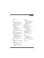
Index
S
Screw Kit, spare part numbers
3–27, 3–35, 3–37
screw listing A–1
security cable slot 1–8
serial number 3–1, 5–2
service considerations 4–2
Setup Utility 2–1
speaker assembly
removal 5–30
spare part number 3–3,
3–36, 5–30
speaker assembly cable,
disconnection 5–32
speakers 1–15
specifications
battery 6–6
computer 6–1
display 6–3, 6–4
DVD/CD-RW Combo
Drive 6–7
DVD±RW/R and CD-RW
Combo Drive 6–9
hard drive 6–5
I/O addresses 6–14
interrupts 6–12
optical drive 6–7
system DMA 6–11
static shielding materials 4–8
stop button 1–18
S-Video-out jack
location 1–8
pin assignments D–3
Maintenance and Service Guide
switch cover
removal 5–22
spare part number 3–3,
3–35, 5–22
system board
removal 5–74
spare part numbers 3–7,
3–32, 3–37, 3–38, 5–74
system DMA 6–11
T
thermal pad, locations 5–81,
5–83
thermal paste, locations 5–81,
5–83
tools required 4–1
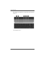
top components 1–14, 1–16,
1–19
top cover
removal 5–47
spare part number 3–5,
3–35, 5–47
top cover support trim
removal 5–65
spare part number 3–5,
3–35, 5–65
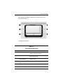
TouchPad 1–19
TouchPad buttons 1–19
TouchPad light 1–19
TouchPad on/off button 1–19
TouchPad vertical scroll zone
1–19
transporting precautions 4–5
troubleshooting
audio 2–25
docking device 2–18
Index–7