1
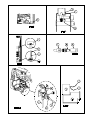
- Push “TEMP SET” again for five seconds.
- “E” “r” appears for one second and then pauses for
two seconds.
- The cycle continues to repeat as long as this display
screen is active.
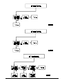
Diagnostic Screen #7: Inputs
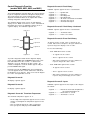
The screen number appears in the left display. The individual
segments appear in the right display for these inputs to the
refrigerator controls:
Segment 1 ............ Door of the fresh food compartment is
closed and interior light is off.
Segment 2 ............ Burner flame is sensed.
Segment 3 ............ Thermistor is sensed.
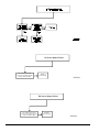
Diagnostic Screen #8: Outputs
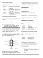
The screen number appears in the left display. The individual
segments appear in the right display for these outputs from
the refrigerator controls:
Segment 1 ............ The power board is supplying
the AC heater.
Segment 2 ............ The power board is supplying
the DC heater.
Segment 3 ............ The power board is supplying
the divider heater.
Segment 4 ............ The power board is supplying
the gas valve.
Segment 5 ............ The power board is supplying
the interior light.
Segment 6 ............ The power board is supplying
the spark electrode.
power to
power to
power to
power to
power to
Ice Maker
(models N620-IM, N621-IM, N820-IM,
and N821-IM)
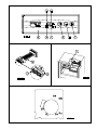
The ice maker is assembled to the refrigerators at the factory
as optional equipment. If the refrigerator does not have a
factory installed ice maker, one can not be added to the
refrigerator at a later time.
The ice maker is fully automatic and will operate in ambient
temperatures as low as 0° F. To allow operation at temperatures between 0° F. and 32° F., the ice maker has a heater on
the solenoid water valve and on the water line between the
solenoid water valve and the ice maker.
CAUTION: The water line heater does not protect the
water supply line from the vehicle shut off valve to the
solenoid water valve on the back of the refrigerator.
The ice maker heater operates on 12 VDC when the refrigerator controls are ON, unless the DC voltage is less than 10.5
VDC. A thermostat (in series with the heater) supplies
voltage to the heater when the ambient temperature is less
than 38° F +/- 4°. The thermostat does not supply voltage to
the heater when the ambient temperature is more than 48° F.
+/- 5°.
When the freezer temperature of the refrigerator is low
enough, the ice maker opens the solenoid water valve and
fills the mold. The ice maker ejects the frozen ice into a
storage bin. As the storage bin fills, the ice raises the ice
maker arm until it turns off the ice maker. As you use the ice
and lower the ice level in the storage bin, the ice maker arm
also lowers. This turns the ice maker on and begins the
process of making ice.
power to
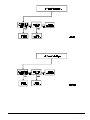
Diagnostic Screen #9: DC Voltage Status
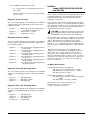
The screen number appears in the left display. The individual
segments of the right display appear for the status of the DC
voltage:
Segment 1 ............ DC voltage high.
Segment 4 ............ DC voltage normal.
Segment 7 ............ DC voltage low.
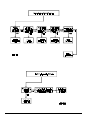
Diagnostic Screen #0: AC Voltage Status
Ice Maker Specifications
120 volts AC (108 VAC min. - 132 VAC max.)
Amp raw (cycle on, mold heater off) - .03 amps
Amp draw (cycle on, mold heater on) - 1.6 amps
Amp draw (cycle off) - 0 amps
12 volts DC (10.5 VDC min. - 15.4 VDC max.)
Amp draw (water line heater) - 1.67 amps (20 W @
12 VDC)
Amp draw (relay) - .083 amps (12 VDC)
Inlet water pressure - 15 min. to 125 max. PSI
Duration of one cycle - 3.5 to 7 minutes
Ice yield - 3 pounds per 24 hours.
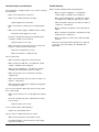
The screen number appears in the left display. The individual
segments of the right display appear for the status of the AC
voltage:
Segment 1 ............ AC voltage high.
Segment 4 ............ AC voltage normal.
Segment 7 ............ AC voltage low.
No Segments ........ No AC voltage.
Service Manual 21