1
CLYMER.
SUZUKI
VS700-800 INTRUDER • 1985-1997
SERVICE • REPAIR • MAINTENANCE
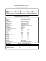
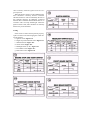
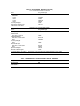
QUICK REFERENCE DATA
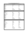
TIRE INFLATION PRESSURE (COLD)*
Psi
28
Load
"Solo riding
Dual riding
32
Tire Pressure Front
Rear kPa
200
225
» Tire inflation pressure for factory equipped tires. Aftermarket tires may
kPa
psi
32
36
225
250
require different inflation pressure.
RECOMMENDED LUBRICANTS AND FLUIDS
Fuel
U.S. and Canada
U.K. and all others
Engine oii
Capacity
Change
"• Change and filter
j> ""At overhaul
C$dlanf
* Capacity at change
^tt»al drive oil
«.
I ~ Capacity at change
'• f rake fluid
'ulch hydraulic fluid
-Hmtterf refilling
5hptnt fork oil capacity (each fork leg)
3 "i
Regular unleaded
87 [(R + M)/2 method] or 91 octane or higher
85-95 octane
SAE 10W-40 API grade SE or SF
2.4 L (2-5 U.S. qtJ2,1 Imp. qt.)
2.8 L (3.0 U.S. qt J2.5 Imp. qt.)
3.3 L(3.5 U.S. qt/2.9 Imp. qt.)
Ethylene glycol
1.7 L (1.8 U.S. qtJ1.5 imp. qt.)
SAi 90 hypoid gear oil with
GL-5 under API classification
2-2.2 m) (6.8-7.0 U.S. qt J7.4-7.7 Imp. qt.)
DOT 4
DOT 3 or DOT 4
Distilled water
SAE 10W
981
,^- Right-hand fork
; Left-hand forte
388 ml
370 ml
12.1 oz.
12.5 oz.
383 mi
394 ml
386 ml
412ml
13.4 oz.
13.8 oz.
13.5 oz.
14.502,
"'t 1985-1989
t990-1991
153 mm
6.02 in.
UJS. and U.K.
Canada
1992-1993
y U.S., Canada and U.K.
' 1994-on
J^»rk oH type
Cables and pivot points
175 mm
187mm
6.89 in.
7.36 in.
;,:if8<M981
;.: u,s.
r '"" U.K.
*, /It92-1993
'f: W§4-on
J*Brflr*l fork oil leyet dimension
•
178 mm
7.01 in.
177mm
6.97 in.
SAE 10W fork oil
Cabie lube or SAE 10W/30 motor oil
f;
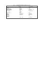
MAINTENANCE
Item
^•Oil drain plug
/ \telve adjuster locknut
Cylinder head side cover bolts
(side opposite spark plug)
AND TUNE UP TIGHTENING TORQUES
N.m
ft.-lb.
18-23
13-16
13-16.5
9.5-11.5
21-23
15-18
INTRODUCTION
This detailed, comprehensive manual covers the U.S
and U.K. models of the Suzuki Intruder 700-800 cc Vtwins from 1985-on.
The expert text gives complete information on maintenance, tune-up, repair and overhaul. Hundreds of photos
and drawings guide you through every step. The book
includes all you will need to know to keep your Suzuki
running right. Throughout this book where differences
occur among the models, they are clearly identified.
A shop manual is a reference. You want to be able to
find information fast. As in all Clymer books, this one is
designed with you in mind. All chapters are thumb tabbed.
Important items are extensively indexed at the rear of the
book. All procedures, tables, photos, etc., in this manual
are for the reader who may be working on the bike for the
first time or using this manual for the first time. All the
most frequently used specifications and capacities are
summarized in the Quick Reference Data pages at the
front of the book.
Keep the book handy in your tool box. It will help you
better understand how your bike runs, lower repair costs
and generally improve your satisfaction with the bike.
CHAPTER ONE
GENERAL INFORMATION
This detailed, comprehensive manual covers the
U.S. and the U.K. models of the Suzuki Intruder
700-800 cc V-twins from 1985-on. Table 1 lists the
chassis numbers (VIN) for models covered in this
manual.
Troubleshooting, tune-up, maintenance and repair
are not difficult, if you know what tools and equipment to use and what to do. Step-by-step instructions
guide you through jobs ranging from simple maintenance to complete engine and suspension overhaul.
This manual can be used by anyone from a first
time do-it-yourselfer to a professional mechanic.
Detailed drawings and clear photographs give you
all the information you need to do the work right.
Some procedures will require the use of special
tools. The resourceful mechanic can, in many cases,
think of acceptable substitutes for special tools, there
is always another way. This can be as simple as using
a few pieces of threaded rod, washers and nuts to
remove or install a bearing or fabricating a tool from
scrap material. However, using a substitute for a
special tool is not recommended as it can be dangerous to and may damage the part. If you find that a
tool can be designed and safely made, but will
require some type of machine work, you may want
to search out a local community college or high
school that has a machine shop curriculum. Some
shop teachers welcome outside work that can be
used as practical shop applications for advanced
students.
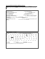
Table 1 lists model coverage with VIN and frame
serial numbers. Metric and U.S. standards are used
throughout this manual and U.S. to metric conversion is given in Table 2.
Tables 1-5 are located at the end of this chapter.
MANUAL ORGANIZATION
This chapter provides general information and
discusses equipment and tools useful both for preventive maintenance and troubleshooting.
Chapter Two provides methods and suggestions
for quick and accurate diagnosis and repair of problems. Troubleshooting procedures discuss typical
symptoms and logical methods to pinpoint the
trouble.
Chapter Three explains all periodic lubrication
and routine maintenance necessary to keep your
Suzuki operating well and competitive. Chapter
Three also includes recommended tune-up procedures, eliminating the need to constantly consult
other chapters on the various assemblies.
Subsequent chapters describe specific systems
such as the engine top end, engine bottom end,
clutch, transmission, fuel, exhaust, electrical, cooling, suspension, drive train, steering and brakes.
Each chapter provides disassembly, repair and assembly procedures in simple step-by-step form. If a
repair is impractical for a home mechanic, it is so
indicated. It is usually faster and less expensive to
take such repairs to a Suzuki dealer or competent
repair shop. Specifications concerning a particular
system are included at the end of the appropriate
chapter.
NOTES, CAUTIONS
AND WARNINGS
The terms NOTE, CAUTION and WARNING
have specific meanings in this manual. A NOTE
provides additional information to make a step or
procedure easier or clearer. Disregarding a NOTE
could cause inconvenience, but would not cause
damage or personal injury.
A CAUTION emphasizes an area where equipment damage could occur. Disregarding a CAUTION could cause permanent mechanical damage;
however, personal injury is unlikely.
A WARNING emphasizes an area where personal
injury or even death could result from negligence.
Mechanical damage may also occur. WARNINGS
are to be taken seriously. In some cases, serious
injury and death has resulted from disregarding
similar warnings.
SAFETY FIRST
Professional mechanics can work for years and
never sustain a serious injury. If you observe a few
rules of common sense and safety, you can enjoy
many safe hours servicing your own machine. If you
ignore these rules you can hurt yourself or damage
the equipment.
1. Never use gasoline as a cleaning solvent.
2. Never smoke or use a torch in the vicinity of
flammable liquids, such as cleaning solvent, in open
containers.
3. If welding or brazing is required on the machine,
remove the fuel tank and rear shock to a safe dis
tance, at least 50 feet away.
4. Use the proper sized wrenches to avoid damage
to fasteners and injury to yourself.
5. When loosening a tight or stuck nut, be guided
by what would happen if the wrench should slip. Be
careful; protect yourself accordingly.
6. When replacing a fastener, make sure to use one
with the same measurements and strength as the old
one. Incorrect or mismatched fasteners can result in
damage to the bike and possible personal injury.
Beware of fastener kits that are filled with cheap and
poorly made nuts, bolts, washers and cotter pins.
Refer to Fasteners in this chapter for additional
information.
7. Keep all hand and power tools in good condition.
Wipe greasy and oily tools after using them. They
are difficult to hold and can cause injury. Replace or
repair worn or damaged tools.
8. Keep your work area clean and uncluttered.
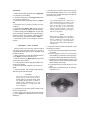
9. Wear safety goggles during all operations involv
ing drilling, grinding, the use of a cold chisel or
anytime you feel unsure about the safety of your
eyes. Safety goggles should also be worn anytime
solvent and compressed air is used to clean a part.
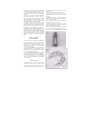
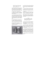
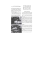
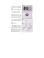
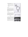
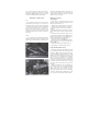
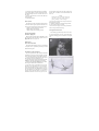
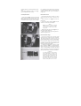
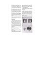
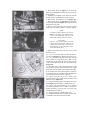
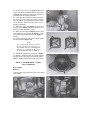
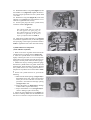
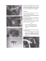
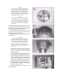
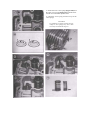
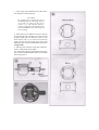
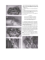
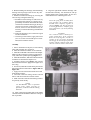
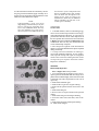
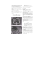
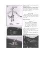
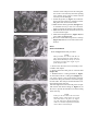
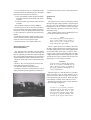
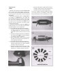
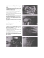
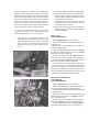
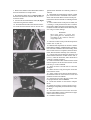
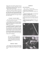
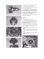
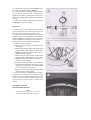
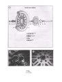
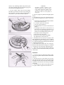
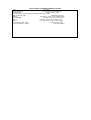
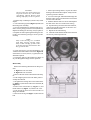
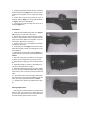
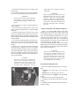
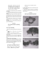
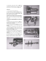
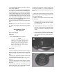
10. Keep an approved fire extinguisher nearby (Fig
ure 1). Be sure it is rated for gasoline (Class B) and
electrical (Class C) fires.
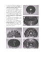
11. When drying bearings or other rotating pans
with compressed air, never allow the air jet to rotate
the bearing or part. The air jet is capable of rotating
them at speeds far in excess of those for which they
were designed. The bearing or rotating part is very
likely to disintegrate and cause serious injury and
damage. To prevent bearing damage when using
compressed air, hold the inner bearing race by hand
(Figure 2).
SERVICE HINTS
Most of the service procedures covered are
straightforward and can be performed by anyone
reasonably handy with tools. It is suggested, however, that you consider your own capabilities carefully before attempting any operation involving
major disassembly of the engine or transmission.
Take your time and do the job right. Do not forget
that a newly rebuilt engine must be broken-in the
same way as a new one. Keep the rpm within the
limits given in your owner's manual when you get
back on the road or out in the dirt.
1. "Front," as used in this manual, refers to the front
of the bike; the front of any component is the end
closest to the front of the bike. The "left-" and "righthand" sides refer to the position of the parts as viewed
by a rider sitting on the seat facing forward. For exam
ple, the throttle control is on the right-hand side. These
rules are simple, but confusion can cause a major
inconvenience during service.
2. Whenever servicing the engine or clutch, or when
removing a suspension component, the bike should
be secured in a safe manner.
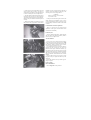
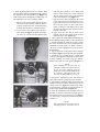
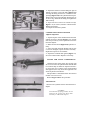
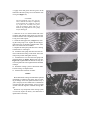
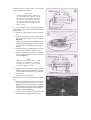
WARNING
Never disconnect the positive (+) battery cable unless the negative (-) cable
has first been disconnected. Disconnecting the positive cable while the
negative cable is still connected may
cause a spark. This could ignite hydrogen gas given off by the battery, causing
an explosion.
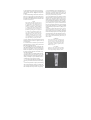
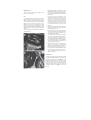
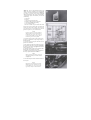
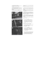
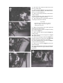
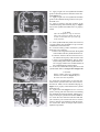
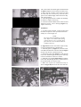
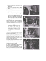
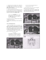
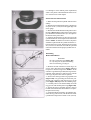
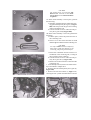
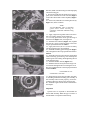
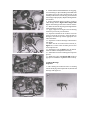
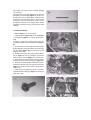
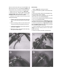
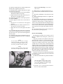
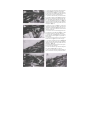
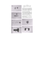
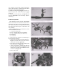
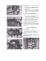
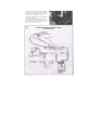
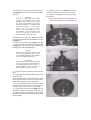
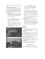
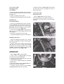
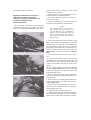
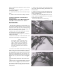
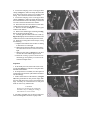
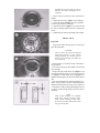
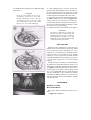
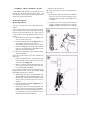
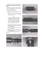
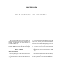
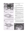
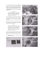
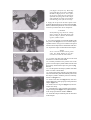
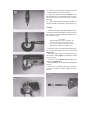
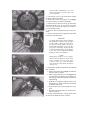
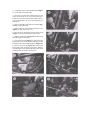
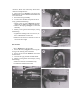
3. Disconnect the negative battery cable (Figure 3)
when working on or near the electrical, clutch, or
starter systems and before disconnecting any elec
trical wires. On most batteries, the negative terminal
will be marked with a minus (-) sign and the positive
terminal with a plus (+) sign.
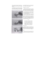
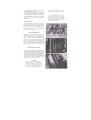
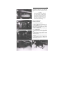
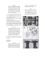
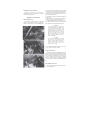
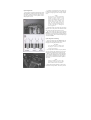
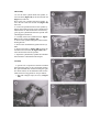
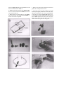
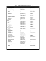
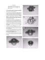
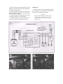
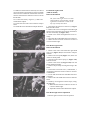
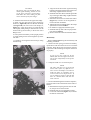
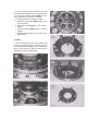
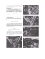
4. Tag all similar internal parts for location and
mark all mating parts for position (A, Figure 4).
Record number and thickness of any shims as they
are removed. Small parts such as bolts can be iden
tified by placing them in plastic sandwich bags (B,
Figure 4). Seal and label them with masking tape.
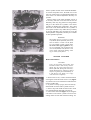
5. Place parts from a specific are of the engine (e.g.
cylinder head, cylinder, clutch, shift mechanism,
etc.) into plastic boxes (C, Figure 4) to keep them
separated.
6. When disassembling transmission shaft assem
blies, use an egg flat (the type that restaurants get
their eggs in) (D, Figure 4) and set the parts from
the shaft in one of the depressions in the same order
in which is was removed.
NOTE
Some of the procedures or service specifications listed in this manual may not
be applicable if your Suzuki has been
modified or if it has been equipped with
non-stock equipment. When modifying
or installing non-stock equipment, file
all printed instruction or technical information regarding the new equipment
in a folder or notebook for future reference. If your Suzuki was purchased second hand, the previous owner may have
installed non-stock parts. If necessary,
consult with your dealer or the accessory manufacturer on components that
may affect tuning or repair procedures.
1. Wiring should be tagged with masking tape and
marked as each wire is removed. Again, do not rely
on memory alone.
8. Finished surfaces should be protected from
physical damage or corrosion. Keep gasoline and
brake fluid off painted surfaces.
9. Use penetrating oil on frozen or tight bolts, then
strike the bolt head a few times with a hammer and
punch (use a screwdriver on screws). Avoid the use
of heat where possible, as it can warp, melt or affect
the temper of parts. Heat also ruins finishes, espe
cially paint and plastics.
10. No parts removed or installed (other than bush
ings and bearings) in the procedures given in this
manual should require unusual force during disas
sembly or assembly. If a part is difficult to remove
or install, find out why before proceeding.
11. Cover all openings after removing parts or com
ponents to prevent dirt, small tools, etc. from falling
in.
12. Read each procedure completely while looking
at the actual parts before starting a job. Make sure
you thoroughly understand what is to be done and
then carefully follow the procedure, step-by-step.
13. Recommendations are occasionally made to re
fer service or maintenance to a Suzuki dealer or a
specialist in a particular field. In these cases, the
work will be done more quickly and economically
than if you performed the job yourself.
14. In procedural steps, the term "replace" means to
discard a defective part and replace it with a new or
exchange unit. "Overhaul" means to remove, disas
semble, inspect, measure, repair or replace defective
parts, reassemble and install major systems or parts.
15. Some operations require the use of a hydraulic
press. Unless you have a press, it would be wiser to
have these operations performed by a shop equipped
for such work, rather than to try to do the job yourself
with makeshift equipment that may damage your
machine.
16. Repairs go much faster and easier if your ma
chine is clean before you begin work. There are
many special cleaners on the market, like Simple
Green or Bel-Ray Degreaser, for washing the engine
and related parts. Follow the manufacturer's direc
tions on the container for the best results. Clean all
oily or greasy parts with cleaning solvent as you
remove them.
WARNING
Never use gasoline as a cleaning agent.
It presents an extreme fire hazard. Be
sure to work in a well-ventilated area
when using cleaning solvent. Keep afire
extinguisher, rated for gasoline fires,
handy in any case.
CAUTION
If you use a car wash to clean your bike,
don't direct the high pressure water hose
at steering bearings, carburetor hoses,
suspension linkage components, wheel
bearings and electrical components.
The water will flush grease out of the
bearings or damage the seals.
17. Much of the labor charges for repairs made by
dealers are for the time involved during in the re
moval, disassembly, assembly, and reinstallation of
other parts in order to reach the defective part. It is
frequently possible to perform the preliminary op
erations yourself and then take the defective unit to
the dealer for repair at considerable savings.
18. If special tools are required, make arrangements
to get them before you start. It is frustrating and
time-consuming to get partly into a job and then be
unable to complete it.
19. Make diagrams (or take a Polaroid picture)
wherever similar-appearing parts are found. For in
stance, crankcase bolts are often not the same length.
You may think you can remember where everything
came from—but mistakes are costly. There is also
the possibility that you may be sidetracked and not
return to work for days or even weeks—in which the
time carefully laid out parts may have become dis
turbed.
20. When assembling parts, be sure all shims and
washers are replaced exactly as they came out.
21. Whenever a rotating part butts against a station
ary part, look for a shim or washer. Use new gaskets
if there is any doubt about the condition of the old
ones. A thin coat of oil on non-pressure type gaskets
may help them seal more effectively.
22. High spots may be sanded off a piston with
sandpaper, but fine emery cloth and oil will do a
much more professional job.
23. Carbon can be removed from the head, the
piston crowns and the exhaust ports with a dull
screwdriver. Do not scratch machined surfaces.
Wipe off the surface with a clean cloth when fin
ished.
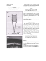
24. A baby bottle makes a good measuring device
for adding oil to the front forks. Get one that is
graduated in fluid ounces and cubic centimeters.
After it has been used for this purpose, do not let a
small child drink out of it as there will always be an
oil residue in it.
25. If it is necessary to make a clutch cover or
ignition cover gasket and you do not have a suitable
old gasket to use as a guide, you can use the outline
of the cover and gasket material to make a new
gasket. Apply engine oil to the cover gasket surface.
Then place the cover on the new gasket material and
apply pressure with your hands. The oil will leave a
very accurate outline on the gasket material that can
be cut around.
CAUTION
When purchasing gasket material to make
a gasket, measure the thickness of the old
gasket and purchase gasket material with
the same approximate thickness.
26. Heavy grease can be used to hold small parts in
place if they tend to fall out during assembly. How
ever, keep grease and oil away from electrical and
brake components.
27. The carburetor is best cleaned by disassembling
it and soaking the parts in a commercial cleaning
solvent. Never soak gaskets and rubber parts in these
cleaners. Never use wire to clean out jets and air
passages. They are easily damaged. Use compressed
air to blow out the carburetor only if the float has
been removed first.
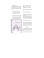
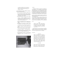
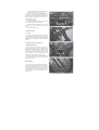
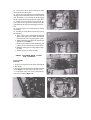
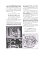
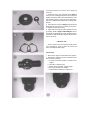
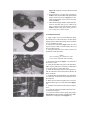
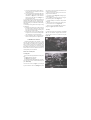
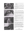
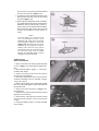
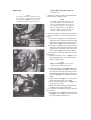
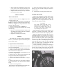
28. There are many items available that can be used
on your hands before and after working on your bike.
A little preparation prior to getting "all greased up"
will help when cleaning up later. Before starting out,
work Vaseline, soap or a product such as Invisible
Glove (Figure 5) onto your forearms, into your
hands and under your fingernails and cuticles. This
will make cleanup a lot easier. For cleanup, use a
waterless hand soap such as Sta-Lube and then finish
up with powdered Boraxo and a fingernail brush
(Figure 6).
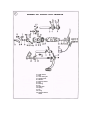
PARTS REPLACEMENT
When you order parts from the dealer or other
parts distributor, always order by frame and engine
serial numbers. Refer to Table 1. Compare new parts
to old before purchasing them. If they are not alike,
have the parts manager explain the difference to you.
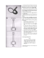
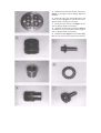
TORQUE SPECIFICATIONS
Torque specifications throughout this manual are
given in Newton-meters (N.m) and foot-pounds (ft.lb.).
Existing torque wrenches calibrated in meter kilograms can be used by performing a simple conversion. All you have to do is move the decimal point
one place to the right; for example, 3.5 mkg = 35
N.m. This conversion is accurate enough for mechanical work even though the exact mathematical
conversion is 3.5 mkg = 34.3 N-m.
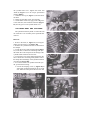
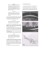
Refer to Table 3 for general torque specifications
for various size screws, bolts and nuts that may not
be listed in the respective chapters. To use the table,
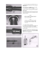
first determine the size of the bolt or nut. Use a
vernier caliper and measure the inside dimension of
the threads of the nut (Figure 7) and across the
threads for a bolt (Figure 8).
FASTENERS
The materials and designs of the various fasteners
used on your Suzuki are not arrived at by chance or
accident. Fastener design determines the type of tool
required to work the fastener. Fastener material is
carefully selected to decrease the possibility of
physical failure.
Nuts, bolts and screws are manufactured in a wide
range of thread patterns. To join a nut and bolt, the
diameter of the bolt and the diameter of the hole in
the nut must be the same. It is just as important that
the threads on both be properly matched.
The best way to tell if the threads on 2 fasteners
are matched is to turn the nut on the bolt (or the bolt
into the threaded hole in a piece of equipment) with
fingers only. Be sure both pieces are clean. If much
force is required, check the thread condition on each
fastener. If the thread condition is good but the
fasteners jam, the threads are not compatible. A
thread pitch gauge (Figure 9) can also be used to
determine pitch. Suzuki motorcycles are manufac-
tured with ISO (International Organization for
Standardization) metric fasteners. The threads are
cut differently than that of American fasteners (Figure 10).
ened. Left-hand threads are used in locations where
normal rotation of the equipment would tend to
loosen a right-hand threaded fastener.
Most threads are cut so that the fastener must be
turned clockwise to tighten it. These are called righthand threads. Some fasteners have left-hand threads;
they must be turned counterclockwise to be light-
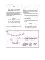
ISO Metric Screw Threads
ISO (International Organization for Standardization) metric threads come in 3 standard thread
sizes: coarse, fine and constant pitch. The ISO coarse
pitch is used for most all common fastener applications. The fine pitch thread is used on certain precision tools and instruments. The constant pitch thread
is used mainly on machine pans and not for fasteners. The constant pitch thread, however, is used on
all metric thread spark plugs.
ISO metric threads are specified by the capital
letter M followed by the diameter in millimeters and
the pitch (or the distance between each thread) in
millimeters separated by the sign x. For example a
M8 x 1.25 bolt is one that has a diameter of 8
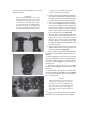
millimeters with a distance of 1.25 millimeters between each thread. The measurement across 2 flats
on the head of the bolt (Figure 11) indicates the
proper wrench size to be used. Figure 12 shows how
to determine bolt diameter.
NOTE
When purchasing a bolt from a dealer
or parts store, it is important to know
how to specify bolt length. The correct
way to measure bolt length is by measuring the length starting from underneath the bolt head to the end of the bolt
(Figure 13). Always measure bolt
length in this manner to avoid purchasing bolts that are too long or too short.
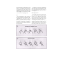
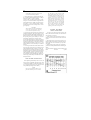
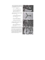
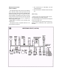
Machine Screws
There are many different types of machine screws.
Figure 14 shows a number of screw heads requiring
different types of turning tools. Heads are also designed to protrude above the metal (round) or to be
slightly recessed in the metal (flat). See Figure 15.
Bolts
Commonly called bolts, the technical name for
these fasteners is cap screws. Metric bolts are described by the diameter and pitch (or the distance
between each thread). For example a M8 x 1.25 bolt
is one that has a diameter of 8 millimeters and a
distance of 1.25 millimeters between each thread.
The measurement across 2 flats on the head of the
bolt (Figure 11) indicates the proper wrench size to
be used. Use a vernier caliper and measure across
the threads (Figure 12) to determine the bolt diameter and to measure the length (Figure 13).
To indicate the size of a metric nut, manufacturers
specify the diameter of the opening and the thread
pitch. This is similar to bolt specifications, but without the length dimension. The measurement across
2 flats on the nut indicates the proper wrench size to
be used (Figure 17).
Nuts
Several types of bolts, screws and nuts incorporate a system that develops an interference between
the bolt, screw, nut or tapped hole threads. Interference is achieved in various ways: by distorting
threads, coating threads with dry adhesive or nylon,
distorting the top of an all-metal nut, using a nylon
insert in the center or at the top of a nut, etc.
Self-locking fasteners offer greater holding
strength and better vibration resistance. Some prevailing torque fasteners can be reused if in good
condition. Others, like the nylon insert nut, form an
initial locking condition when the nut is first in-
Nuts are manufactured in a variety of types and
sizes. Most are hexagonal (6-sided) and fit on bolts,
screws and studs with the same diameter and pitch.
Figure 16 shows several types of nuts. The
common nut is generally used with a lockwasher.
Self-locking nuts have a nylon insert which prevents the nut from loosening; no lockwasher is
required. Wing nuts are designed for fast removal
by hand. Wing nuts are used for convenience in
non-critical locations.
Self-locking Fasteners
OPENINGS FOR TURNING TOOLS
MACHINE SCREWS
stalled; the nylon forms closely to the bolt thread 1
pattern, thus reducing any tendency for the nut to I
loosen. When the nut is removed, the locking efficiency is greatly reduced. For greatest safety, it is
recommended that you install new self-locking fasteners whenever they are removed.
Washers
There are 2 basic types of washers: flat washers
and lockwashers. Flat washers are simple discs with
a hole to fit a screw or bolt. Lockwashers are designed to prevent a fastener from working loose due
to vibration, expansion and contraction. Figure 18
shows several types of washers. Washers are also
used in the following functions:
a. As spacers.
b. To prevent galling or damage of the equipment
by the fastener.
c. To help distribute fastener load during torquing.
d. As seals.
Note that flat washers are often used between a
lockwasher and a fastener to provide a smooth bearing surface. This allows the fastener to be turned
easily with a tool.
Cotter Pins
Cotter pins (Figure 19) are used to secure fasteners in a special location. The threaded stud, bolt or
axle must have a hole in it. Its nut or nut lock piece
has castellations around its upper edge into which
the cotter pin fits to keep it from loosening. When
properly installed, a cotter pin is a positive locking
device.
The first step in properly installing a cotter pin is
to purchase one that will fit snugly when inserted
through the nut and the mating thread part. This
should not be a problem when purchasing cotter pins
through a Suzuki dealer; you can order them by their
respective part numbers. However, when you purchase them at a hardware or automotive store, keep
this in mind. The cotter pin should not be so tight
that you have to drive it in and out, but you do not
want it so loose that it can move or float after it is
installed.
Before installing a cotter pin, tighten the nut to the
recommended torque specification. If the castellations in the nut do not line up with the hole in the
bolt or axle, tighten the nut until alignment is
achieved. Do not loosen the nut to make alignmentInsert a new cotter pin through the nut and hole, then
tap the head lightly to seat it. Bend one arm over the
flat on the nut and the other against the top of the
axle or bolt. Cut the arms to a suitable length to
prevent them from snagging on clothing, or worse,
your hands, arms or legs; the exposed arms will cut
flesh easily. When the cotter pin is bent and its arms
cut to length, it should be tight. If you can wiggle the
cotter pin, it is improperly installed.
Cotter pins should not be reused as their ends may
break and allow the cotter pin to fall out and perhaps
the fastener to unscrew itself.
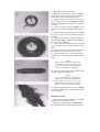
Circlips
Circlips can be internal or external design. They
are used to retain items on shafts (external type) or
within bores (internal type). In some applications,
circlips of varying thicknesses are used to control the
end play of parts assemblies. These are often called
selective circlips. Circlips should be replaced during
installation, as removal weakens and deforms them.
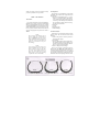
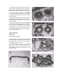
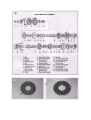
Two basic styles of circlips are available: machined and stamped circlips. Machined circlips (Figure 20) can be installed in either direction (shaft or
housing) because both faces are machined, thus creating two sharp edges. Stamped circlips (Figure 21)
are manufactured with one sharp edge and one
rounded edge. When installing stamped circlips in a
thrust situation (transmission shafts, fork tubes,
etc.), the sharp edge must face away from the part
producing the thrust. When installing circlips, observe the following:
a. Compress or expand circlips only enough to
install them.
b. After the circlip is installed, make sure it is
completely seated in its groove.
Transmission circlips become worn with use and
increase side play. For this reason, always use new
circlips when ever a transmission is to be reassembled.
LUBRICANTS
Periodic lubrication assures long life for any type
of equipment. The type of lubricant used is just as
important as the lubrication service itself, although
in an emergency the wrong type of lubricant is better
than none at all. The following paragraphs describe
the types of lubricants most often used on motorcycle equipment. Be sure to follow the manufacturer's
recommendations for lubricant types.
Generally, all liquid lubricants are called "oil."
They may be mineral-based (including petroleum
bases), natural-based (vegetable and animal bases),
synthetic-based or emulsions (mixtures). "Grease"
is an oil to which a thickening base has been added
so that the end product is semi-solid. Grease is often
classified by the type of thickener added; lithium
soap is commonly used.
Engine Oil
Four-cycle oil for motorcycle and automotive engines is graded by the American Petroleum Institute
(API) and the Society of Automotive Engineers
(SAE) in several categories. Oil containers display
these ratings on the top or label.
API oil grade is indicated by letters; oils for gasoline engines are identified by an "S". Suzuki models
described in this manual require SE or SF graded oil.
Viscosity is an indication of the oil's thickness.
The SAE uses numbers to indicate viscosity; thin
oils have low numbers while thick oils have high
numbers. A "W" after the number indicates that the
viscosity testing was done at low temperature to
simulate cold-weather operation. Engine oils fall
into the 5 to 50 range.
Multi-grade oils (for example 10W-40) are less
viscous (thinner) at low temperatures and more viscous (thicker) at high temperatures. This allows the
oil to perform efficiently across a wide range of |
engine operating conditions. The lower the number,
the better the engine will start in cold climates.
Higher numbers are usually recommended for engine running in hot weather conditions.
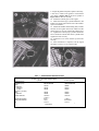
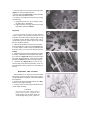
Grease
Greases are graded by the National Lubricating
Grease Institute (NLGI). Greases are graded by
number according to the consistency of the grease;
these range from No. 000 to No. 6, with No. 6 being
the most solid. A typical multipurpose grease is
NLGI No. 2. For specific applications, equipment
manufacturers may require grease with an additive
such as molybdenum disulfide (MOS2) (Figure 22).
RTV GASKET SEALANT
Room temperature vulcanizing (RTV) sealant is
used on some pre-formed gaskets and to seal some
components. RTV is a silicone gel supplied in tubes
and can be purchased in a number of different colors.
Moisture in the air causes RTV to cure. Always
place the cap on the tube as soon as possible when
using RTV sealants?RTV has a shelf life of one year
and will not cure properly when the shelf life has
expired. Check the expiration date on RTV tubes
before using and keep partially used tubes tightly
sealed.
Applying RTV Sealant
Clean all gasket residue from mating surfaces.
Surfaces should be clean and free of oil and dirt.
Remove all RTV gasket material from blind attaching holes, as it can cause a "hydraulic" effect and
affect bolt torque.
Apply RTV sealant in a continuous bead. Circle
all mounting holes unless otherwise specified.
Torque mating parts within 10 minutes after application.
THREADLOCK
A chemical such as "Loctite." A locking compound will lock fasteners against vibration loosening and seal against leaks. Loctite 242 (blue) and 271
(red) are recommended for many threadlock requirements described in this manual.
Loctite 242 (blue) is a medium strength threadlock and component disassembly can be performed
with normal hand tools. Loctite 271 (red) is a high
strength threadlock and heat or special tools, such as
a press or puller, may be required for component
disassembly.
Applying Threadlock
Surfaces should be clean and free of oil, grease,
dirt and other residue; clean threads with an aerosol
electrical contact cleaner before applying the Loctite. When applying Loctite, use a small amount. If
too much is used, it may work its way into parts not
meant to be stuck together.
GASKET REMOVER
Stubborn gaskets can present a problem during
engine service as they can take a long time to remove. Consequently, there is the added problem of
secondary damage occurring to the gasket mating
surfaces from the incorrect use of gasket scraping
tools. To quickly and safely remove stubborn gaskets, use a spray gasket remover. Spray gasket remover can be purchased through automotive parts
houses. Follow the manufacturer's directions for
use.
EXPENDABLE SUPPLIES
Certain expendable supplies are required during
maintenance and repair work. These include grease,
oil. gasket cement, wiping rags and cleaning solvent.
Ask your dealer for the special locking compounds,
silicone lubricants and other products (Figure 23)
which make bike maintenance simpler and easier.
Cleaning solvent or kerosene is available at some
service stations, paint or hardware stores.
WARNING
Having a stack of clean shop rags on
hand is important when performing engine and suspension service work. However, to prevent the possibility of fire
damage from spontaneous combustion
from a pile of solvent soaked rags, store
them in a lid sealed metal container
until they can be washed or discarded.
NOTE
To avoid absorbing solvent and other
chemicals into your skin while cleaning
parts, wear a pair of petroleum-resistant
rubber gloves. These can be purchased
through industrial supply houses or wellequipped hardware stores.
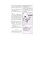
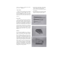
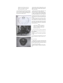
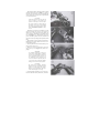
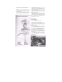
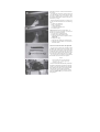
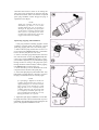
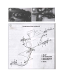
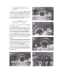
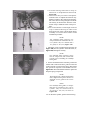
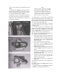
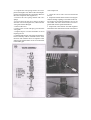
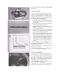
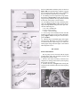
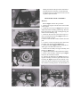
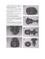
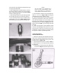
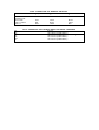
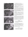
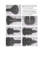
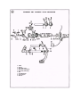
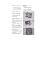
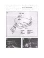
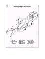
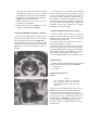
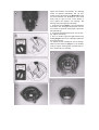
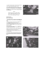
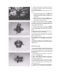
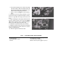
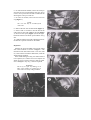
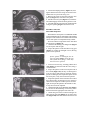
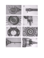
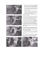
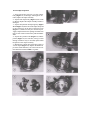
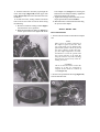
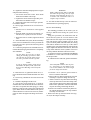
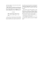
PARTS REPLACEMENT
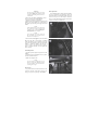
Suzuki makes frequent changes during a model
year, some minor, some relatively major. When you
order parts from the dealer or other parts distributor,
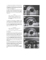
always order by frame and engine numbers. The
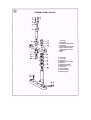
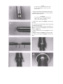
frame number serial number is stamped on the righthand side of the steering head (Figure 24). The
vehicle identification number (VIN) plate is attached to the left-hand side of the frame down tube
(Figure 25). The engine number is stamped on a
raised pad on the right-hand side of the crankcase
(Figure 26) behind the starter motor cover. The
carburetor number (Figure 27) is on the side of the
carburetor body below the top cover.
Write the numbers down and carry them with you.
Compare new parts to old before purchasing them. If
they are not alike, have the parts manager explain the
difference to you. Table 1 lists engine and frame serial
numbers for the models covered in this manual.
NOTE
If your Suzuki was purchased secondhand and you are not sure of its model
year, use the bike's VINandframe serial
numbers and the information listed in
Table 1. Read your bike's serial number.
Then compare the numbers listed in Table 1. If your bike's serial number is
listed in Table 1, cross-reference the
number with the adjacent model number and year.
BASIC HAND TOOLS
Many of the procedures in this manual can be
carried out with simple hand tools and test equipment familiar to the average home mechanic.
Keep your tools clean and in a tool box. Keep them
organized with the sockets and related drives together, the open-end combination wrenches together, etc. After using a tool, wipe off dirt and
grease with a clean cloth and return the tool to its
correct place.
Top quality tools are essential; they are also more
economical in the long run. If you are now starting
to build your tool collection, stay away from the
"advertised specials" featured at some parts houses,
discount stores and chain drug stores. These are
usually a poor grade tool that can be sold cheaply
and that is exactly what they are—cheap. They are
usually made of inferior material, and are thick,
heavy and clumsy. Their rough finish makes them
difficult to clean and they usually don't last very
long. If it is ever your misfortune to use such tools,
you will probably find out that the wrenches do not
fit the heads of bolts and nuts correctly and damage
the fastener.
Quality tools are made of alloy steel and are heat
treated for greater strength. They are lighter and
better balanced than cheap ones. Their surface is
smooth, making them a pleasure to work with and
easy to clean. The initial cost of good quality tools
may be more but they are cheaper in the long run.
Don't try to buy everything in all sizes in the beginning; do it a little at a time until you have the
necessary tools.
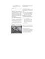
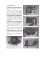
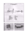
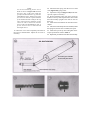
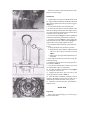
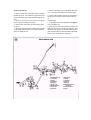
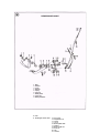
The following tools are required to perform virtually any repair job on a bike. Each tool is described
and the recommended size given for starting a tool
collection. Table 4 includes the tools that should be
on hand for simple home repairs and/or major over-
haul as shown in Figure 28. Additional tools and
some duplicates may be added as you become more
familiar with the bike. Almost all motorcycles and
vehicles (with the exception of the U.S. built Harley
Davidson and some English motorcycles) use metric
size bolts and nuts. If you are starting your collection
now, buy metric sizes.
Screwdrivers
The screwdriver is a very basic tool, but if used
improperly it will do more damage than good. The
slot on a screw has a definite dimension and shape.
A screwdriver must be selected to conform with that
shape. Use a small screwdriver for small screws and
a large one for large screws or the screw head will
be damaged.
Two basic types of screwdrivers are required:
common (flat-blade) screwdrivers (Figure 29) and
Phillips screwdrivers (Figure 30).
Note the following when selecting and using
screwdrivers:
a. The screwdriver must always fit the screw
head. If the screwdriver blade is too small for
the screw slot, damage may occur to the screw
slot and screwdriver. If the blade is too large, it
cannot engage the slot properly and will result
in damage to the screw head.
b. Standard screwdrivers are identified by the
length of their blade. A 6-inch screwdriver has
ablade six inches long. The width of the screw
driver blade will vary, so make sure that the
blade engages the screw slot the complete
width of the screw.
c. Phillips screwdrivers are sized according to
their point size. They are numbered one, two,
three and four. The degree of taper determines
the point size; the No. 1 Phillips screwdriver
will be the most pointed. The points become
more blunt as their number increases.
NOTE
You should also be aware of another
screwdriver similar to the Phillips, and
that is the Reed and Prince tip. Like the
Phillips, the Reed and Prince screwdriver tip forms an "X" but with one
major exception, the Reed and Prince
tip has a much more pointed tip. The
Reed and Prince screwdriver should
never be used on Phillips screws and
vise versa. Intermixing these screwdrivers will cause damage to the screw and
screwdriver. If you have both types in
your tool box and they are similar in
appearance, you may want to identify
them by painting the screwdriver shank
underneath the handle.
d. When selecting screwdrivers, note that you can
apply more power with less effort with a longer
screwdriver than with a short one. Of course,
there will be situations where only a short
handle screwdriver can be used. Keep this in
mind though, when having to remove tight
screws.
e. Because the working end of a screwdriver receives quite a bit of abuse, you should purchase
screwdrivers with hardened-tips. The extra
money will be well spent. Screwdrivers are
available in sets which often include an
assortment of common and Phillips blades. If
you buy them individually, buy at least the following:
a. Common screwdriver—5/16 x 6 in. blade.
b. Common screwdriver—3/8 x 12 in. blade.
c. Phillips screwdriver—size 2 tip, 6 in. blade.
d. Phillips screwdriver—size 3 tip, 6 and 8 in.
blade.
Use screwdrivers only for driving screws. Never
use a screwdriver for prying or chiseling metal. Do
not try to remove a Phillips, Torx or Allen head screw
with a standard screwdriver (unless the screw has a
combination head that will accept either type); you
can damage the head so that the proper tool will be
unable to remove it.
Keep screwdrivers in the proper condition and
they will last longer and perform better. Always keep
the tip of a standard screwdriver in good condition.
Figure 31 shows how to grind the tip to the proper
shape if it becomes damaged. Note the symmetrical
sides of the tip.
Pliers
Pliers come in a wide range of types and sizes.
Pliers are useful for cutting, bending and crimping.
They should never be used to cut hardened objects
or to turn bolts or nuts. Figure 32 shows several
pliers useful in repairing your Suzuki.
Each type of pliers has a specialized function.
Slip-joint pliers are general purpose pliers and are
used mainly for holding things and for bending.
Needlenose pliers are used to hold or bend small
objects. Water pump pliers can be adjusted to hold
various sizes of objects; the jaws remain parallel to
grip around objects such as pipe or tubing. There are
many more types of pliers.
CAUTION
Pliers should not be used for loosening
or tightening nuts or bolts. The pliers'
sharp teeth will grind off the nut or bolt
corners and damage it.
CAUTION
If slip-joint or water pump pliers are
going to be used to hold an object with
a finished surface, wrap the object with
tape or cardboard for protection.
Vise-grip Pliers
Vise-grip pliers (Figure 33) are used to hold objects very tightly while another task is performed on
the object. While vise-grip pliers work well, caution
should be followed with their use. Because vise-grip
pliers exert more force than regular pliers, their
sharp jaws can permanently scar the object. In addition, when vise-grip pliers are locked into position,
they can crush or deform thin wall material.
Vise-grip pliers are available in many types for
more specific tasks.
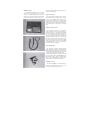
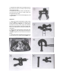
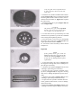
Circlip (Snap Ring) Pliers
Circlip pliers (Figure 34) are special in that they
are only used to remove circlips from shafts or
within engine or suspension housings. When purchasing circlip pliers, there are two kinds to distinguish from. External pliers (spreading) are used to
remove circlips that fit on the outside of a shaft.
Internal pliers (squeezing) are used to remove circlips which fit inside a gear or housing.
WARNING
Because circlips can sometimes slip and
"fly off" during removal and installation, always wear safety glasses.
Box-end, Open-end and Combination Wrenches
Box-end, open-end and combination wrenches
are available in sets or separately in a variety of sizes.
On open- and box-end wrenches, the number
stamped near the end refers to the distance between
2 parallel flats on the hex head bolt or nut. On
combination wrenches, the number is stamped near
the center.
Box-end wrenches require clear overhead access
to the fastener but can work well in situations where
the fastener head is close to another part. They grip
on all six edges of a fastener for a very secure grip.
They are available in either 6-point or 12-point. The
6-point gives superior holding power and durability
but requires a greater swinging radius. The 12-point
works better in situations with limited swinging
radius.
jaws make them unstable for situations where the
bolt or nut is sunken in a well or close to the edge of
a casting. These wrenches grip only two flats of a
fastener so if either the fastener head or the wrench
jaws are worn, the wrench may slip off.
Combination wrenches (Figure 35) have openend on one side and box-end on the other with both
ends being the same size. These wrenches are favored by professionals because of their versatility.
Open-end wrenches are speedy and work best in
areas with limited overhead access. Their wide flat
Adjustable (Crescent) Wrenches
An adjustable wrench (sometimes called crescent
wrench) can be adjusted to fit nearly any nut or bolt
head which has clear access around its entire perimeter. Adjustable wrenches (Figure 36) are best used
as a backup wrench to keep a large nut or bolt from
turning while the other end is being loosened or
tightened with a proper wrench.
Adjustable wrenches have only two gripping surfaces which make them more subject to slipping off
the fastener, damaging the part and possibly injuring your hand. The fact that one jaw is adjustable
only aggravates this shortcoming.
These wrenches are directional; the solid jaw must
be the one transmitting the force. If you use the
adjustable jaw to transmit the force, it will loosen
and possibly slip off.
Adjustable wrenches come in all sizes but something in the 6 to 8 in. range is recommended as an
all-purpose wrench.
Socket Wrenches
This type is undoubtedly the fastest, safest and
most convenient to use. Sockets which attach to a
ratchet handle (Figure 37) are available with 6-point
or 12-point openings and 1/4,3/8 and 3/4 in. drives.
The drive size indicates the size of the square hole
which mates with the ratchet handle (Figure 38).
Allen Wrenches
Allen wrenches (Figure 39) are available in sets
or separately in a variety of sizes. These sets come
in SAE and metric size, so be sure to buy a metric
set. Allen bolts are sometimes called socket bolts.
Sometimes the bolts are difficult to reach and it is
suggested that a variety of Allen wrenches be pur-
chases (e.g. socket driven, T-handle and extension
type) as shown in Figure 40.
b. Inspect hammers for damaged or broken parts.
Repair or replace the hammer as required. Do
not use a hammer with a taped handle.
Torque Wrench
c. Always wipe oil or grease off of the hammer
before using it.
A torque wrench is used with a socket to measure
how tightly a nut or bolt is installed. They come in
a wide price range and with either 3/8 or 1/2 in.
square drive (Figure 41). The drive size indicates
the size of the square drive which mates with the
socket. Purchase one that measures 0-280 N-m (0200 ft.-lb.).
d. The head of the hammer should always strike
the object squarely. Do not use the side of the
hammer or the handle to strike an object.
Impact Driver
This tool might have been designed with the bike
in mind. This tool makes removal of fasteners easy
and minimizes damage to bolts and screw slots.
Impact drivers and interchangeable bits (Figure 42)
are available at most large hardware, motorcycle and
auto parts stores. Don't purchase a cheap one as they
do not work as well and require more force (the "use
a larger hammer" syndrome) than a moderately
priced one. Sockets can also be used with a hand
impact driver. However, make sure that the socket is
designed for use with an impact driver or air tool.
Do not use regular hand sockets, as they may shatter
during use.
Hammers
The correct hammer (Figure 43) is necessary for
repairs. A hammer with a face (or head) of rubber or
plastic or the soft-faced type that is filled with buckshot is sometimes necessary in engine tear downs.
Never use a metal-faced hammer on engine or suspension parts, as severe damage will result in most
cases. Ball-peen or machinist's hammers will be
required when striking another tool, such as a punch
or impact driver. When striking a hammer against a
punch, cold chisel or similar tool, the face of the
hammer should be at least 1/2 in. larger than the head
of the tool. When it is necessary to strike hard against
a steel part without damaging it, a brass hammer
should be used. A brass hammer can be used because
brass will give when striking a harder object. When
using hammers, note the following: a. Always wear
safety glasses when using a hammer.
e. Always use the correct hammer for the job.
Tap and Die Set
Acomplete tap and die set is a relatively expensive
tool. But when you need a tap or die to clean up a
damaged thread, there is really no substitute. Be sure
to purchase one for metric threads when working on
your Suzuki.
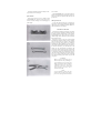
Tire Levers
When changing tires, use a good set of tire levers.
Never use a screwdriver in place of a tire lever; refer
to Chapter Ten for tire changing procedures using
these tools. Before using the tire levers, check the
working ends of the tool and remove any burrs.
Don't use a tire lever for prying anything but tires.
For better leverage when changing tires on your
Suzuki, you may want to invest in a set of 16 in. long
tire irons. These can be ordered through your dealer.
Drivers and Pullers
These tools are used to remove and install oil
seals, bushings, bearings and gears. These will be
called out during service procedures in later chapters
as required.
PRECISION MEASURING TOOLS
Measurement is an important part of motorcycle
service. When performing many of the service procedures in this manual, you will be required to make
a number of measurements. These include basic
checks such as valve clearance, engine compression
and spark plug gap. As you get deeper into engine
disassembly and service, measurements will be required to determine the size and condition of the
piston and cylinder bore, valve and guide wear,
camshaft wear, crankshaft runout and so on. When
making these measurements, the degree of accuracy
will dictate which tool is required. Precision measuring tools are expensive. If this is your first experience at engine or suspension service, it may be more
worthwhile to have the checks made at a Suzuki
dealer or machine shop. However, as your skills and
enthusiasm increase for doing your own service
work, you may want to begin purchasing some of
these specialized tools. The following is a description of the measuring tools required during engine
and suspension overhaul.
Feeler Gauge
Feeler gauges come in assorted sets and types
(Figure 44). The feeler gauge is made of either a
piece of a flat or round hardened steel of a specified
thickness. Wire gauges are frequently recommended
to measure spark plug gap. Flat gauges are used for
all other measurements. Feeler gauges are also designed for specialized uses, such as for measuring
valve clearances. On these gauges, the gauge end is
usually small enough and angled so as to make
checking valve clearances easier.
Vernier Caliper
This tool (Figure 45) is invaluable when reading
inside, outside and depth measurements to within
close precision. It can be used to measure clutch
spring length and the thickness of clutch plates,
shims and thrust washers.
Outside Micrometers
One of the most reliable tools used for precision
measurement is the outside micrometer (Figure 46).
Outside micrometers will be required to measure
valve shim thickness, piston diameter and valve
stem diameter. Outside micrometers are also used
with other tools to measure the cylinder bore and the
valve guide inside diameters. Micrometers can be
purchased individually or as a set.
Dial Indicator
Dial indicators (Figure 47) are precision tools
used to check dimension variations on machined
parts such as transmission shafts and axles and to
check crankshaft and axle shaft end play. Dial indicators are available with various dial types for different measuring requirements.
Cylinder Bore Gauge
The cylinder bore gauge is a very specialized
precision tool. The gauge set shown in Figure 48 is
comprised of a dial indicator, handle and a number
of length adapters to adapt the gauge to different
bore sizes. The bore gauge can be used to make
cylinder bore measurements such as bore size, taper
and out-of-round. Depending on the bore gauge, it
can sometimes be used to measure brake caliper and
master cylinder bore sizes. An outside micrometer
must be used together with the bore gauge to determine bore dimensions.
Small Hole Gauges
A set of small hole gauges allow you to measure
a hole, groove or slot ranging in size up to 13 mm
(0.500 in.). A small hole gauge will be required to
measure valve guide, brake caliper and brake master
cylinder bore diameters. An outside micrometer
must be used together with the small hole gauge to
determine bore dimensions.
Compression Gauge
An engine with low compression cannot be properly tuned and will not develop full power. A compression gauge (Figure 49) measures engine
compression. The one shown has a flexible stem
with an extension that can allow you to hold it while
kicking the engine over. Open the throttle all the way
when checking engine compression. See Chapter
Three.
Cylinder Leak Down Tester
By positioning a cylinder on its compression
stroke so that both valves are closed and then pressurizing the cylinder, you can isolate engine problem
areas (e.g. leaking valve, damaged head gasket, broken, worn or stuck piston rings) by listening for
escaping air through the carburetors, exhaust pipe,
cylinder head mating surface, etc. To perform this
procedure, a leak down tester and an air compressor
are required. This procedure is described in Chapter
Three. Cylinder leak down testers can be purchased
through Suzuki dealers, accessory tool manufacturers and automotive tool suppliers.
Strobe Timing Light
This instrument is useful for checking ignition
timing. By flashing a light at the precise instant the
spark plug fires, the position of the timing mark can
be seen. The flashing light makes a moving mark
appear to stand still opposite a stationary mark.
Suitable lights range from inexpensive neon bulb
types to powerful xenon strobe lights (Figure 50). A
light with an inductive pickup is recommended to
eliminate any possible damage to ignition wiring.
Use according to manufacturer's instructions.
Multimeter or VOM
This instrument (Figure 51) is invaluable for electrical system troubleshooting. See Electrical Troubleshooting in Chapter Eight for its use.
Screw Pitch Gauge
A screw pitch gauge (Figure 52) determines the
thread pitch of bolts, screws, studs, etc. The gauge
is made up of a number of thin plates. Each plate has
a thread shape cut on one edge to match one thread
pitch. When using a screw pitch gauge to determine
a thread pitch size, try to fit different blade sizes onto
the bolt thread until both threads match (Figure 53).
Magnetic Stand
A magnetic stand (Figure 54) is used to securely
hold a dial indicator when checking the runout of a
round object or when checking the end play of a
shaft.
V-Blocks
V-blocks (Figure 55) are precision ground blocks
used to hold a round object when checking its runout
or condition. In motorcycle repair. V-blocks can be
used when checking the runout of such items as
valve stems, camshaft, balancer shaft, crankshaft,
wheel axles and fork tubes.
Surface Plate
A surface plate can be used to check the flatness
of parts or to provide a perfectly flat surface for
minor resurfacing of cylinder head or other critical
gasket surfaces. While industrial quality surface
plates are quite expensive, the home mechanic can
improvise. A thick metal plate can be put to use as a
surface plate. The metal surface plate with a piece of
sandpaper or dry wall surface sanding sheets glued
to its surface can be used for cleaning and smoothing
cylinder head and crankcase mating surfaces.
NOTE
Check with a local machine shop on the
availability and cost of having a metal
plate resurfaced/or use as a surface plate.
SPECIAL TOOLS
A few special tools may be required for major
service. These are described in the appropriate chapters and are available either from a Suzuki dealer or
other manufacturers as indicated.
This section describes special tools unique to this
type of bike's service and repair.
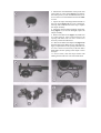
Spoke Wrench
This special wrench is used to tighten wheel
spokes (Figure 56). Always use the correct size
wrench to avoid rounding out and damaging the
spoke nipple.
The Grabbit
The Grabbit (Figure 57) is a special tool used to
hold the clutch boss when removing the clutch nut
and to secure the drive sprocket when removing the
sprocket nut.
Other Special Tools
A few other special tools may be required for
major service. These are described in the appropriate
chapters and are available from Suzuki dealers or
other manufacturers as indicated.
CLEANING SOLVENT
With the environmental concern that is prevalent
today concerning the disposal of hazardous solvents,
the home mechanic should select a water soluble,
biodegradable solvent. These solvents can be purchased through dealers, automotive parts houses and
large hardware stores.
Selecting a solvent is only one of the problems
facing the home mechanic when it comes to cleaning
parts. You need some type of tank to clean parts as
well as to store die solvent. There are a number of
manufacturers offering different types and sizes of
parts cleaning tanks. While a tank may seem a luxury
to the home mechanic, you will find that it will
quickly pay for itself through its efficiency and
convenience. When selecting a parts washer, look
for one that can recycle and store the solvent, as well
as separate the sludge and contamination from the
clean solvent. Most important, check the warranty,
if any, as it pertains to the tank's pump. Like most
tools, when purchasing a parts washer, you get what
you pay for.
WARNING
Having a stack of clean shop rags on
hand is important when performing engine work. However, to prevent the possibility of fire damage from spontaneous
combustion from a pile of solventsoaked rags, store them in a lid-sealed
metal container until they can be
washed or discarded.
NOTE
To avoid absorbing solvent and other
chemicals into your skin while cleaning
parts, wear a pair of petroleum-resistant
rubber gloves. These can be purchased
through industrial supply houses or
well-equipped hardware stores.
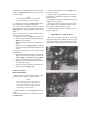
MECHANIC'S TIPS
Removing Frozen Nuts and Screws
When a fastener rusts and cannot be removed,
several methods may be used to loosen it. First,
apply penetrating oil such as Liquid Wrench or
WD-40 (available at hardware or auto supply
stores). Apply it liberally and let it penetrate for
10-15 minutes. Rap the fastener several times with
a small hammer; do not hit it hard enough to cause
damage. Reapply the penetrating oil if necessary.
For frozen screws, apply penetrating oil as described, then insert a screwdriver in the slot and rap
the top of the screwdriver with a hammer. This
loosens the rust so the screw can be removed in the
normal way. If the screw head is too chewed up to
use this method, grip the head with vise-grip pliers
and twist the screw out.
Avoid applying heat unless specifically instructed, as it may melt, warp or remove the temper
from parts.
Removing Broken Screws or Bolts
When the head breaks off a screw or bolt, several
methods are available for removing the remaining
portion.
If a large portion of the remainder projects out, try
gripping it with vise-grips. If the projecting portion
is too small, file it to fit a wrench or cut a slot in it
to fit a screwdriver. See Figure 58.
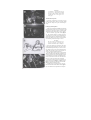
If the head breaks off flush, use a screw extractor.
To do this, center punch the exact center of the
remaining portion of the screw or bolt. Drill a small
hole in the screw and tap the extractor into the hole.
Back the screw out with a wrench on the extractor.
See Figure 59.
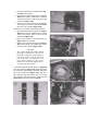
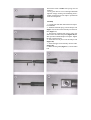
Remedying Stripped Threads
Occasionally, threads are stripped through carelessness or impact damage. Often the threads can be
cleaned up by running a tap (for internal threads on
nuts) or die (for external threads on bolts) through
the threads. See Figure 60. To clean or repair spark
plug threads, a spark plug tap can be used (Figure
61).
NOTE
Tap and dies can be purchased individually or in a set as shown in Figure 62.
If an internal thread is damaged, it may be necessary to install a Helicoil (Figure 63) or some other
type of thread insert. Follow the manufacturer's
instructions when installing their insert.
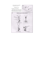
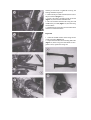
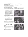
Removing Broken or Damaged Studs
If a stud is broken or the threads severely damaged, perform the following. A tube of red Loctite
(No. 271), 2 nuts, 2 wrenches and a new stud will be
required during this procedure. Studs that are
stripped or damaged will require the use of a stud
remover.
1. Thread two nuts onto the damaged stud. Then
tighten the 2 nuts against each other so that they are
locked.
NOTE
If the threads on the damaged stud do
not allow installation of the 2 nuts,
you will have to remove the stud with
a stud remover.
2. Turn the bottom nut counterclockwise and un
screw the stud.
3. Threaded holes with a bottom surface should be
blown out with compressed air as dirt buildup in the
bottom of the hole may prevent the stud from being
torqued properly. If necessary, use a bottoming tap
to true up the threads and to remove any deposits.
4. Install 2 nuts on the top half of the new stud as in
Step 1. Make sure they are locked securely.
5. Coat the bottom half of a new stud with red
Loctite (No. 271),
6. Turn the top nut clockwise and thread the new
stud securely.
7. Remove the nuts and repeat for each stud as
required.
8. Follow Loctite's directions on cure time before
assembling the component.
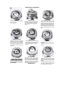
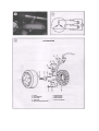
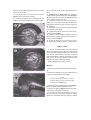
BALL BEARING REPLACEMENT
Ball bearings (Figure 64) are used throughout
your Suzuki's engine and chassis to reduce power
loss, heat and noise resulting from friction. Because
ball bearings are precision made parts, they must be
maintained by proper lubrication and maintenance.
When a bearing is found to be damaged, it should be
replaced immediately. However, when installing a
new bearing, care should be taken to prevent damage
to the new bearing. While bearing replacement is
described in the individual chapters where applicable, the following can be used as a guideline.
NOTE
Unless otherwise specified, install bearings with the manufacturer's mark or
number on the bearing facing outward.
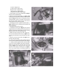
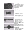
Bearing Removal
While bearings are normally removed only when
damaged, there may be times when it is necessary to
remove a bearing that is in good condition. Depending on the situation, you may be able to remove the
bearing without damaging it. However, bearing removal in some situations, no matter how careful you
are, will cause bearing damage. Care should always
be given to bearings during their removal to prevent
secondary damage to the shaft or housing. Note the
following when removing bearings.
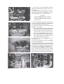
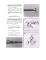
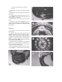
1. When using a puller to remove a bearing from a
shaft, care must be taken so that shaft damage does
not occur. Always place a piece of metal between the
end of the shaft and the puller screw. In addition,
place the puller arms next to the inner bearing race.
See Figure 65.
2. When using a hammer to remove a bearing from
a shaft, do not strike the hammer directly against the
shaft. Instead, use a brass or aluminum spacer be
tween the hammer and shaft (Figure 66). In addi
tion, make sure to support both bearing races with
wood blocks as shown in Figure 66.
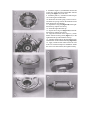
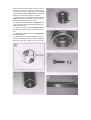
3. The most ideal method of bearing removal is with
a hydraulic press. However, certain procedures must
be followed or damage may occur to the bearing,
shaft or case half. Note the following when using a
press:
a. Always support the inner and outer bearing
races with a suitable size wood or aluminum
spacer ring (Figure 67). If only the outer race
is supported, the balls and/or the inner race will
be damaged.
b. Always make sure the press ram (Figure 67)
aligns with the center of the shaft. If the ram is
not centered, it may damage the bearing and/or
shaft.
c. The moment the shaft is free of the bearing, it
will drop to the floor. Secure or hold the shaft
to prevent it from falling.
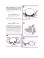
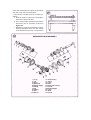
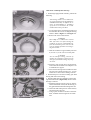
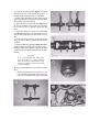
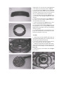
Bearing Installation
1. When installing a bearing in a housing, pressure
must be applied to the outer bearing race (Figure
68). When installing a bearing on a shaft, pressure
must be applied to the inner bearing race (Figure
69).
2. When installing a bearing as described in Step 1,
some type of driver will be required. Never strike the
bearing directly with a hammer or the bearing will
be damaged. When installing a bearing, a piece of
pipe or a socket with an outer diameter that matches
the bearing race will be required. Figure 70 shows
the correct way to use a socket and hammer when
installing a bearing over a shaft. 3. Step 1 describes
how to install a bearing in a case half and over a
shaft. However, when installing a bearing over a
shaft and into a housing at the same time, a snug fit
will be required for both outer and inner bearing
races. In this situation, a spacer must be installed
underneath the driver tool so that pressure is
applied evenly across both races. See Figure 71. If
the outer race is not supported as shown in Figure
71, the balls will push against the outer bearing
track and damage it.
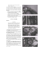
Shrink Fit
1. Installing a bearing over a shaft: When a tight fit
is required, the bearing inside diameter will be
smaller than the shaft. In this case, driving the bearing on the shaft using normal methods may cause
bearing damage. Instead, the bearing should be
heated before installation. Note the following:
a. Secure the shaft so that it can be ready for
bearing installation.
b. Clean the bearing surface on the shaft of all
residue. Remove burrs with a file or sandpaper.
c. Fill a suitable pot or beaker with clean mineral
oil. Place a thermometer (rated higher than
248° F [120° C]) in the oil. Support the ther
mometer so that it does not rest on the bottom
or side of the pot.
d. Remove the bearing from its wrapper and se
cure it with a piece of heavy wire bent to hold
it in the pot. Hang the bearing in the pot so that
it does not touch the bottom or sides of the pot.
e. Turn the heat on and monitor the thermometer.
When the oil temperature rises to approximately 248° F (120° C), remove the bearing
from the pot and quickly install it. If necessary,
place a socket on the inner bearing race and tap
the bearing into place. As the bearing chills, it
will tighten on the shaft so you must work
quickly when installing it. Make sure the bearing
is installed all the way.
2. Installing a bearing in a housing: Bearings are
generally installed in a housing with a slight interference fit. Driving the bearing into the housing
using normal methods may damage the housing or
cause bearing damage. Instead, the housing should
be heated before the bearing is installed. Note the
following:
CAUTION
Before heating the crankcases in this
procedure to remove the bearings, wash
the cases thoroughly with detergent and
water. Rinse and rewash the cases as
required to remove all traces of oil and
other chemical deposits.
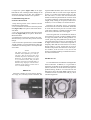
a. The housing must be heated to a temperature
of about 212° F (100° C) in an oven or on ahot
plate. An easy way to check to see that it is at
the proper temperature is to drop tiny drops of
water on the case as it heats up; if they sizzle
and evaporate immediately, the temperature is
correct. Heat only one housing at a time.
CAUTION
Do not heat the housing with a torch
(propane or acetylene). Never bring a
flame into contact with the bearing or
housing. The direct heat will destroy the
case hardening of the bearing and will
likely warp the housing.
b. Remove the housing from the oven or hot plate
and hold onto the housing with a kitchen pot
holder, heavy gloves or heavy shop cloths—it
is hot.
NOTE
A suitable size socket and extension
works well for removing and installing bearings.
c. Hold the housing with the bearing side down
and tap the bearing out. Repeat for all bearings
in the housing.
d. Before installing new bearings, heat the hous
ing halves and place the new bearings in a
freezer, if possible. Chilling the bearings will
slightly reduce their overall diameter while the
hot housing assembly is slightly larger due to
heat expansion. This will make installation
much easier.
NOTE
Always install bearings with the manufacturer's mark or number facing outward.
e. While the housing is still hot, install the new
bearing(s) into the housing. Install the bearings
by hand, if possible. If necessary, lightly tap the
bearing(s) into the housing with a socket
placed on the outer bearing race. Do not install
new bearings by driving on the inner bearing
race. Install the bearing(s) until it seats com
pletely.
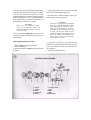
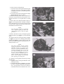
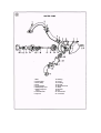
OIL SEALS
Oil seals (Figure 72) are used to prevent leakage
of oil, water, grease or combustion gasses from
between a housing and a shaft. Improper removal of
a seal can damage the housing or shaft. Improper
installation of the seal can damage the seal. Note the
following:
a. Prying is generally the easiest and most effective method of removing a seal from a housing.
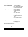
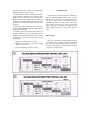
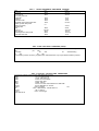
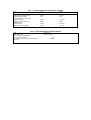
Table 2 DECIMAL AND METRIC EQUIVALENTS
Fractions
1/64
1/32
3/64
1/16
5/64
3/32
7/64
1/8
9/64
5/32
11/64
3/16
13/64
7/32
15/64
1/4
17/64
9/32
19/64
5/16
21/64
11/32
23/64
3/8
25/64
13/32
27/64
7/16
29/64
15/32
31/64
1/2
Decimal
in.
0.015625
0.03125
0.046875
0.0625
0.078125
0.09375
0.109375
0.125
0.140625
0.15625
0.171875
0.1875
0.203125
0.21875
0.234375
0.250
0.265625
0.28125
0.296875
0.3125
0.328125
0.34375
0.359375
0.375
0.390625
0.40625
0.421875
0.4375
0.453125
0.46875
0.484375
0.500
M etric mm
Fractions
0.39688
0.79375
1.19062
1.58750
1.98437
2.38125
2.77812
3.1750
3.57187
3.96875
4.36562
4.76250
5.15937
5.55625
5.95312
6.35000
6.74687
7.14375
7.54062
7.93750
8.33437
8.73125
9.12812
9.52500
9.92187
10.31875
10.71562
11.11250
11.50937
11.90625
12.30312
12.70000
33/64
17/32
35/64
9/16
37/64
19/32
39/64
5/8
41/64
21/32
43/64
11/16
45/64
23/32
47/64
3/4
49/64
25/32
51/64
13/16
53/64
27/32
55/64
7/8
57/64
29/32
59/64
15/16
61/64
31/32
63/64
1
Decimal
in.
0.515625
0.53125
0.546875
0.5625
0.578125
0.59375
0.609375
0.625
0.640625
0.65625
0.671875
0.6875
0.703125
0.71875
0.734375
0.750
0.765625
0.78125
0.796875
0.8125
0.828125
0.84375
0.859375
0.875
0.890625
0.90625
0.921875
0.9375
0.953125
0.96875
0.984375
1.00
Table 3 STANDARD TIGHTENING TORQUES
Conventional or "4" Marked bolt*
Bolt diameter (mm)
N.m
ft.-lb.
4
5
6
8
10
12
14
16
18
1-2
2-4
4-7
0.7-1.5
1.5-3.0
3-5
7-11.5
16-25.5
25.5-40
36-58
58-94
94-137.5
10-16
22-35
35-55
50-80
80-130
130-190
"7" Marked bolt*
Bolt diameter (mm)
N.m
ft.-lb.
4
5
6
8
10
12
14
1.5-3
1-2
2-4.5
6-8.5
13-20
29-43.5
50.5-72.5
79.5-115.5
3-6
8-12
18-28
40-60
70-100
110-160
(continued)
Metric
mm
13.09687
13.49375
13.89062
14.28750
14.68437
15.08125
15.47812
15.87500
16.27187
16.66875
17.06562
17.46250
17.85937
18.25625
18.65312
19.05000
19.44687
19.84375
20.24062
20.63750
21.03437
21.43125
22.82812
22.22500
22.62187
23.01875
23.41562
23.81250
24.20937
24.60625
25.00312
25.40000
Table 3 STANDARD TIGHTENING TORQUES (continued)
16
170-250
123-181 18
200-280
144-202
* Number is marked on top of Suzuki bolt head. These are Suzuki numbers and do not appear on aftermarket
bolts.
Table 4 WORKSHOP TOOLS Tool
Size or specification
Screwdriver Common
1/8 x 4 in. blade Common
5/16x8 in. blade Common
3/8 x 1 2 in. blade Phillips
Size 2 tip, 6 in. overall Pliers Slip joint
6 in. overall Vise Grips
1 0 in. overall Needlenose
6 in. overall Channel lock
12 in. overall Snap ring
Assorted Wrenches Box-end set
Assorted Open-end set
Assorted Crescent
6 in. and 1 2 in. overall Socket set
1/2 in. drive ratchet with assorted
metric sockets Socket drive extensions
1/2 in. drive, 2 in., 4 in. and 6 in. Socket
universal joint
1/2 in. drive Allen
Socket driven (long and short), T-handle driven and 90° Hammers Soft faced
— Plastic faced
— Metal faced
—
Other special tools Impact driver
1/2 in. drive with assorted bits Torque
wrench
1/2 in. driver (ft.-lb.) Flat feeler gauge
Metric set
Table 5 WINDCHILL FACTORS
Estimated
Actual thermometer reading (°F) wind speed
5Q
4Q
3Q
_1Q
_2Q
_3Q
_4Q
_5Q
_g0 in mph Equivalent temperature (°F)
2Q
1Q
Q
Calm
50
40
30
20
10
0
-10
-20
-30
-40
-50
-60 5
48
37
27
16
6
-5
-15
-26
-36
-47
-57
-68 10
40
28
16
4
-9
-21 ["-33
-46
-58
-70
-83
-95 15
36
22
9
-5
-18 [ -36
-45
-58
-72
-85
-99
-112 20
32
18
4
-10 I -25
-39
-53
-67 |~-82
-96
-110
-124 25
30
16
0
-15
-29
-44
-59
-74
-88
-104
-118 -133 30
28
13
-2
-18
-33
-48
-63
-79
-94
-109 -125 -140 35
27
11
-4
-20
-35
-49
-67
-82
-98
-113
-129 -145
40
26
10
-6
-21
-37
-53
-69
-85
-100
-116
-132 -148
*
Little danger
Increasing danger
Great danger
•3 ?^. P*°Per y
• Danger from freezing of exposed flesh • clothed person)
'Wind speeds greater than 40 mph have little additional effect.
CHAPTER TWO
TROUBLESHOOTING
Every motorcycle engine requires an uninterrupted supply of fuel and air, proper ignition and
adequate compression. If any of these are lacking,
the engine will not run.
Diagnosing mechanical problems is relatively
simple if you use orderly procedures and keep a few
basic principles in mind.
The troubleshooting procedures in this chapter
analyze typical symptoms and show logical methods
of isolating causes. These are not the only methods.
There may be several ways to solve a problem, but
only a systematic approach can guarantee success.
Never assume anything. Do not overlook the obvious. If you are riding along and the bike suddenly
quits, check the easiest, most accessible problem
spots first. Is there gasoline in the tank? Has a spark
plug wire fallen off?
If nothing obvious turns up in a quick check, look
a little further. Learning to recognize and describe
symptoms will make repairs easier for you or a
mechanic at the shop. Describe problems accurately
and fully. Saying that "it won't run" isn't the same
thing as saying "it quit at high speed and won't
start," or that "it sat in my garage for 3 months and
then wouldn't start."
Gather as many symptoms as possible to aid in
diagnosis. Note whether the engine lost power
gradually or all at once. Remember that the more
complicated a machine is, the easier it is to troubleshoot because symptoms point to specific problems.
After the symptoms are defined, areas which
could cause problems are tested and analyzed.
Guessing at the cause of a problem may provide the
solution, but it can easily lead to frustration, wasted
time and a series of expensive, unnecessary parts
replacements.
You do not need fancy equipment or complicated
test gear to determine whether repairs can be attempted at home. A few simple checks could save a
large repair bill and lost time while the bike sits in a
dealer's service department. On the other hand, be
realistic and don't attempt repairs beyond your abilities. Service departments tend to charge heavily for
putting together a disassembled engine that may
have been abused. Some won't even take on such a
job—so use common sense and don't get in over
your head.
OPERATING REQUIREMENTS
An engine needs 3 basics to run properly: correct
fuel/air mixture, compression and a spark at the
correct time. If one or more are missing, the engine
will not run. Four-stroke engine operating principles
are described under Engine Principles in Chapter
Four. The electrical system is the weakest link of the
3 basics. More problems result from electrical breakdowns than from any other source. Keep that in mind
before you begin tampering with carburetor adjustments and the like.
If the machine has been sitting for any length of
time and refuses to start, check and clean the spark
plugs and then look to the gasoline delivery system.
This includes the fuel tank, fuel pump, fuel filter,
fuel shutoff valve and fuel lines to the carburetors.
Gasoline deposits may have formed and gummed up
the carburetor jets and air passages. Gasoline tends
to lose its potency after standing for long periods.
Condensation may contaminate the fuel with water.
Drain the old fuel (fuel tank, fuel lines and carburetors) and try starting with a fresh tankful.
TROUBLESHOOTING INSTRUMENTS
Chapter One lists the instruments needed and
instruction on their use.
TROUBLESHOOTING ,
When the bike is difficult to start, or won't start at
all, it doesn't help to wear down the battery using
the electric starter. Check for obvious problems even
before getting out your tools. Go down the following
list step-by-step. Do each one; you may be embarrassed to find the engine stop switch off, but that is
better than wearing down the battery.
Engine Fails to Start
If the bike will not start, perform the following
checks in order:
a. Fuel system check.
b. Compression check.
c. Battery check.
d. Ignition system check.
Fuel system check
WARNING
Do not use an open flame to check in
the tank. A serious explosion is certain
to result.
1. Is there fuel in the tank? Remove or open the filler
cap (Figure 1) and rock the bike. Listen for fuel
sloshing around.
2. Is the fuel shutoff valve in the ON position (Fig
ure 2) and on models so equipped, is the vacuum
line to the valve from the engine still connected?
3. Make sure the engine stop switch (Figure 3) is
not in the OFF position.
4. Is the choke in the correct position? The choke
knob should be pulled out (Figure 4) for a cold
engine and pushed in (Figure 5) for a warm engine.
Compression check
A compression test shows how much pressure
builds in a cylinder during starting. If the compression falls below specified levels, the engine will
become difficult to start or will not start. Refer to
Compression Testing in Chapter Three. Interpret results as follows:
a. Normal: Perform the Ignition Check in this
chapter.
b. Abnormal: If the engine compression is low,
perform the procedures listed under Compres
sion Testing in Chapter Three.
Ignition check
Perform the following spark test to determine if
the ignition system is operating properly.
1. Remove one of the spark plugs as described in
Chapter Three.
2. Attach the spark plug wire connector to the spark
plug and touch the spark plug base to a good ground
like the engine cylinder head. Position the spark plug
so you can see the electrodes.
WARNING
During the next step, do not hold the
spark plug, wire or connector with fingers or a serious electrical shock may
result. If necessary, use a pair of insulated pliers to hold the spark plug or
wire. The high voltage generated by the
ignition system could produce serious
or fatal shocks.
3. Crank the engine over with the starter. A fat blue
spark should be evident across the spark plug elec
trodes.
NOTE
If the starter does not operate or if the
starter motor rotates but the engine
does not turn over, refer to Engine Will
Not Crank in this section.
4. If the spark is good, recheck the fuel and com
pression systems.
5. If the spark is not good, check for one or more of
the following:
a. Loose electrical connections.
b. Dirty electrical connections.
c. Loose or broken ignition coil ground wire.
d. Broken or shorted high tension lead to the
spark plug(s).
e. Ignition unit malfunction.
f. Clutch or sidestand switch malfunction.
g. Ignition or engine stop switch malfunction,
h. Blown fuse.
Battery check
If ignition system tests okay, but the starter turns
slowly, service the battery as described under Battery in Chapter Three.
Engine is Difficult to Start
Check for one or more of the following possible
malfunctions:
a. Fouled spark plug(s).
b. Improperly adjusted choke.
c. Intake tube(s) air leak.
d. Contaminated fuel system.
e. Improperly adjusted carburetor(s).
f. Weak ignitor unit.
g. Weak ignition coil(s).
h. Poor compression.
i. Engine and transmission oil too heavy.
Engine Will Not Crank
Check for one or more of the following possible
malfunctions:
a. Blown fuse.
b. Discharged battery.
c. Defective starter motor and/or starter clutch.
d. Seized piston(s).
e. Seized crankshaft bearings.
f. Broken connecting rod(s).
g. Sidestand, neutral or clutch safety switch(s)
malfunction.
h. Engine stop switch malfunction.
i. Defective starter motor button and contact.
ENGINE PERFORMANCE
In the following check list, it is assumed that the
engine runs, but is not operating at peak performance. This will serve as a starting point from which
to isolate a performance malfunction.
Engine Will Not Idle
a. Carburetor(s) incorrectly adjusted.
b.
c.
d.
e.
f.
Fouled or improperly gapped spark plug(s).
Leaking head gasket.
Obstructed fuel line or fuel shutoff valve.
Obstructed fuel filter.
Ignition timing incorrect due to defective igni
tion component(s).
g. Valve clearance incorrect.
Engine Misses at High Speed
a. Fouled or improperly gapped spark plugs.
b. Improper carburetor main jet selection.
c. Ignition timing incorrect due to defective igni
tion component(s).
d. Weak ignition coil(s).
e. Obstructed fuel line or fuel shutoff valve.
f. Obstructed fuel filter.
g. Clogged carburetor jets,
h. Dirty air filter element.
Engine Overheating
a. Incorrect carburetor adjustment or jet selec
tion.
b. Ignition timing retarded due to defective igni
tion component(s).
c. Improper spark plug heat range.
d. Cooling system malfunction.
e. Incorrect coolant level.
f. Oil level low.
g. Oil not circulating properly,
h. Valves leaking.
i. Heavy engine carbon deposits, j.
Dragging brake(s). k. Clutch
slipping.
Engine Overheating
a.
b.
c.
d.
e.
f.
Clogged radiator.
Damaged thermostat.
Worn or damaged radiator cap.
Water pump worn or damaged.
Thermostatic switch malfunction.
Damaged fan blades.
Smoky Exhaust and Engine Runs Roughly
a. Clogged air filter element.
b. Carburetor adjustment incorrect—mixture too
rich.
c. Choke not operating correctly.
d. Water or other contaminants in fuel.
e. Clogged fuel line.
f. Spark plug(s) fouled.
g. Ignition coil(s) defective.
h. Ignitor unit or pickup coil defective, i. Loose
or defective ignition circuit wire(s). j. Short
circuit from damaged wire insulation, k. Loose
battery cable connection. 1. Valve timing
incorrect, m. Intake tube(s) or air filter(s) air leak.
Engine Loses Power at Normal Riding Speed
a. Carburetor incorrectly adjusted.
b. Engine overheating.
c. Ignition timing incorrect due to defective igni
tion component(s).
d. Incorrectly gapped spark plugs.
e. Obstructed muffler.
f. Dragging brake(s).
Engine Lacks Acceleration
a. Carburetor mixture too lean.
b. Clogged fuel line.
c. Ignition timing incorrect due to defective igni
tion component(s).
d. Dragging brake(s).
e. Slipping clutch.
ENGINE NOISES
Often the first evidence of an internal engine
problem is a strange noise. That knocking, clicking
or tapping sound which you never heard before may
be warning you of impending trouble.
While engine noises can indicate problems, they
are difficult to interpret correctly; inexperienced mechanics can be seriously misled by them.
Professional mechanics often use a special stethoscope (which looks like a doctor's stethoscope) for
isolating engine noises. You can do nearly as well
with a "sounding stick" which can be an ordinary
piece of doweling, a length of broom handle or a
section of small hose. By placing one end in contact
with the area to which you want to listen and the
other end near your year, you can hear sounds emanating from that area. The first time you do this, you
may be horrified at the strange sounds coming from
even a normal engine. If you can, have an experienced friend or mechanic help you sort out the
noises.
Consider the following when troubleshooting engine noises:
1. Knocking or pinging during acceleration—
Caused by using a lower octane fuel than recom
mended. May also be caused by poor fuel. Pinging
can also be caused by a spark plug of the wrong heat
range or carbon build-up in the combustion chamber.
Refer to Correct Spark Plug Heat Range and Com
pression Test in Chapter Three.
2. Slapping or rattling noises at low speed or during
acceleration— May be caused by piston slap, i.e.,
excessive piston-cylinder wall clearance.
3. Knocking or rapping while decelerating—Usu
ally caused by excessive rod bearing clearance.
4. Persistent knocking and vibration— Usually
caused by worn main bearing(s).
5. Rapid on-off squeal— Compression leak around
cylinder head gasket or spark plug(s).
6. Valve train noise— Check for the following:
a. Valves adjusted incorrectly.
b. Valve sticking in guide.
c. Low oil pressure.
ENGINE LUBRICATION
An improperly operating engine lubrication system will quickly lead to engine seizure. The engine
oil level should be checked weekly and topped up,
as described in Chapter Three. Oil pump service is
described in Chapter Four.
Oil Consumption High or Engine Smokes
Excessively
a. Worn valve guides.
b. Worn or damaged piston rings.
Excessive Engine Oil Leaks
a. Clogged air filter breather hose(s).
b. Loose engine parts.
c. Damaged gasket sealing surfaces.
Black Smoke
a. Clogged air filter element.
b. Incorrect carburetor fuel level (too high).
c. Choke stuck open.
d. Incorrect main jet (too large).
Gray Smoke
a. Worn valve guide.
b. Worn valve oil seal.
c. Worn piston ring oil ring.
d. Excessive cylinder and/or piston wear.
CLUTCH
The four basic clutch troubles are:
a. Clutch noise.
b. Clutch slipping.
c. Improper clutch disengagement or dragging.
d. Low hydraulic level in master cylinder or air in
hydraulic fluid line.
All clutch troubles, except adjustments, require
partial clutch disassembly to identify and cure the
problem. The troubleshooting chart in Figure 6 lists
clutch troubles and checks to make. Refer to Chapter
Five for clutch service procedures.
TRANSMISSION
The basic transmission troubles are:
a. Excessive gear noise.
b. Difficult shifting.
c. Gears pop out of mesh.
d. Incorrect shift lever operation.
Transmission symptoms are sometimes hard to
distinguish from clutch symptoms. The troubleshooting chart in Figure 7 lists transmission troubles and checks to make. Refer to Chapter Six for
transmission service procedures. Be sure that the
clutch is not causing the trouble before working on
the transmission.
ELECTRICAL PROBLEMS
If bulbs burn out frequently, the cause may be
excessive vibration, loose connections that permit
TRANSMISSION TROUBLESHOOTING
Excessive gear noise
Check:
• Worn bearings
• Worn or damaged gears
• Excessive gear backlash
Difficult shitting
Check:
• Damaged gears
• Damaged shift forks
• Damaged shift drum
• Damaged shift lever assembly
• Incorrect main shaft and countershaft
engagement
• Incorrect clutch disengagement
Gears pop out of mesh
Check:
• Worn gear or transmission shaft splines
• Shift forks worn or bent
• Worn dog holes in gears
• Insufficient shift lever spring tension
• Damaged shift lever linkage
Incorrect shift lever operation
Check:
• Bent shift lever
• Bent or damaged shift lever shaft
• Damaged shift lever linkage or gears
Incorrect shifting after engine
reassembly
Check:
• Missing transmission shaft shims
• Incorrectly installed parts
• Shift forks bent during reassembly
• Incorrectly assembled crankcase
assembly
• Incorrect clutch adjustment
• Incorrectly assembled shift linkage
assembly
sudden current surges, or the installation of the
wrong type of bulb.
Most light and ignition problems are caused by
loose or corroded ground connections. Check these
prior to replacing a bulb or electrical component.
k. Excessive front end loading from non-standard
equipment.
1. Damaged fairing assembly, m.
Loose fairing mounts or brackets.
Stiff Steering
EXCESSIVE VIBRATION
Usually this is caused by loose engine mounting
hardware. If not, it can be difficult to find without
disassembling the engine. High speed vibration may
be due to a bent axle shaft or loose or faulty suspension components. Vibration can also be caused by
the following conditions:
a. Broken frame.
b. Worn drive chain.
c. Improperly balanced wheels.
d. Defective or damaged wheels.
e. Defective or damaged tires.
f. Internal engine wear or damage.
a. Low front tire air pressure.
b. Bent or damaged steering stem or frame (at
steering neck).
c. Loose or worn steering head bearings.
Stiff or Heavy Fork Operation
a.
b.
c.
d.
e.
Incorrect fork springs.
Incorrect fork oil viscosity.
Incorrect fork adjustment.
Excessive amount of fork oil.
Bent fork tubes.
Poor Fork Operation
CARBURETOR TROUBLESHOOTING
Basic carburetor troubleshooting procedures are
found in Figure 8.
FRONT SUSPENSION AND STEERING
Poor handling may be caused by improper tire
pressure, a damaged or bent frame or front steering
components, worn wheel bearings or dragging
brakes. Possible causes of suspension and steering
malfunctions are listed in the following.
Irregular or Wobbly Steering
a. Loose wheel axle nuts.
b. Loose or worn steering head bearings.
c. Excessive wheel hub bearing play.
d. Damaged wheel.
e. Unbalanced wheel assembly.
f. Worn hub bearings.
g. Incorrect wheel alignment,
h. Loose or bent spoke.
i. Bent or damaged steering stem or frame (at
steering neck), j. Tire
incorrectly seated on rim.
a.
b.
c.
d.
e.
f.
g.
Worn or damage fork tubes.
Fork oil level low due to leaking fork seals.
Incorrect fork adjustment(s).
Bent or damaged fork tubes.
Contaminated fork oil.
Worn fork springs.
Heavy front end loading from non-standard
equipment.
Poor Rear Shock Absorber Operation
a. Damper unit leaking.
b. Incorrect rear shock adjustment.
c. Heavy rear end loading from non-standard
equipment.
d. Incorrect loading.
BRAKE PROBLEMS
Sticking disc brakes may be caused by a stuck
piston(s) in a caliper assembly, warped pad shim(s)
or improper rear brake adjustment. See Figure 9 for
disc brake troubles and checks to make. Sticking
brake shoes may be caused by an out-of-round brake
drum.
CARBURETOR TROUBLESHOOTING
Hard starting
Check:
• Choke not operating correctly
• Idle mixture misadjusted
• Air leak at carburetor mount or hose
• Fuel overflow
Fuel overflow
Check:
• Worn float needle valve or dirty seat
• Incorrect float level
• Damaged float bowl O-ring
• Damaged float pin
• Damaged float
Poor idling
Check:
• Idle misadjusted
• Worn idle mixture screw
• Blocked jet or port in carburetor bore
• Air leak at carburetor mount
Poor acceleration
Check:
• Clogged pilot jet
• Float level too high
• Idle mixture misadjusted
Lower power at all speeds
Check:
• Dirty or plugged carburetor passages
• Clogged fuel line
• Clogged fuel tank strainer
• Air leak at carburetor mount
• Dirty air filter
• Loose carburetor jets
Poor power at high speeds
Check:
• Loose or clogged main jet
• Incorrect float level
• Dirty or plugged carburetor passages
Fuel starvation
Check:
• Clogged fuel line
• Carburetor dirty
• Fuel tank strainer clogged or dirty
• Fuel tank dirty
DISK BRAKE TROUBLESHOOTING
Disc brake fluid leakage
Check:
• Loose or damaged line fittings
• Worn caliper piston seals
• Scored caliper piston and/or bore
• Loose banjo bolts
• Damaged sealing washers
• Leaking master cylinder diaphragm
• Leaking master cylinder secondary seal
• Cracked master cylinder housing
• Too high brake fluid level
• Loose master cylinder cover
Brake overheating
Check:
• Warped brake disc
• Incorrect brake fluid
• Caliper piston and/or brake pads
hanging up
• Riding brakes during riding
Brake chatter
Check:
• Warped brake disc
• Loose brake disc
• Incorrect caliper alignment
• Loose front axle nut and/or clamps
• Worn wheel bearings
• Damaged front hub
• Restricted brake hydraulic line
• Contaminated brake pads
Brake locking
Insufficient brakes
Check:
• Air in brake lines
• Worn brake pads
• Low brake fluid level
• Incorrect brake fluid
• Worn brake disc
• Worn caliper piston seals
• Glazed brake pads
• Leaking primary cup seal in
master cylinder
• Contaminated brake pads and/or disc
Brake squeal
Check:
• Contaminated brake pads and/or disc
• Dust or dirt collected behind brake pads
• Loose parts
CHAPTER THREE
LUBRICATION, MAINTENANCE AND TUNE-UP
A motorcycle, even in normal use, is subjected to
tremendous heat, stress and vibration. When neglected, any bike becomes unreliable and actually
dangerous to ride.
To gain the utmost in safety, performance and
useful life from the Suzuki Intruder, it is necessary
to make periodic inspections and adjustments. Frequently minor problems are found during these inspections that are simple and inexpensive to correct
at the time. If they are not found and corrected at this
time they could lead to major and more expensive
problems later on.
Start out by doing simple tune-up, lubrication and
maintenance. Tackle more involved jobs as you become more acquainted with the bike.
Table 1 is a suggested factory maintenance schedule. Tables 1-6 are located at the end of this chapter.
NOTE
Where differences occur relating to the
United Kingdom (U.K.) models they are
identified. If there is no (U.K.) designation relating to a procedure, photo or
illustration it is identical to the United
States (U.S.) models.
ROUTINE CHECKS
The following simple checks should be performed
at each^top at a service station for gas.
Engine Oil Level
Refer to Engine Oil Level Check under Periodic
Lubrication in this chapter.
Fuel
All Intruder engines are designed to use gasoline
that has a pump octane number (R+M)/2 of 85 or
higher or a gasoline with a research octane number
of 89 or higher. The pump octane number is normally
displayed at service station gas pumps. Using a
gasoline with a lower octane number can cause
pinging or spark knock, both conditions of which
can lead to engine damage. Unleaded fuel is recommended because it reduces engine and spark plug
deposits.
When choosing gasoline and filling the fuel tank,
note the following:
a. When filling the tank, do not overfill it. Fuel
expands in the tank due to engine heat or head
ing by the sun. Stop adding fuel when the fuel
level reaches the bottom of the filler tube inside
the fuel tank.
b. To help meet clean air standards in some
areas of the United States and Canada, oxy- I
genated fuels are being used. Oxygenated
fuels are conventional gasolines that are
blended with an alcohol or ether compound
to increase the gasoline's octane. When using
an oxygenated fuel, make sure that it meets
the minimum octane rating as previously
specified.
c. Because oxygenated fuels can damage plastic
and paint, make sure not to spill fuel onto the
fuel tank during fuel stops.
d. An ethanol (ethyl or grain alcohol) gasoline
that contains more than 10 percent ethanol by
volume may cause engine starting and per
formance related problems.
e. Amethanol (methyl or wood alcohol) gasoline
that contains more than 5 percent methanol by
volume may cause engine starting and per
formance related problems. Gasoline that con
tains methanol must have corrosion inhibitors
to protect the metal, plastic and rubber parts in
the fuel system from damage.
f. Suzuki states that you can use a gasoline con
taining no more than 15 percent MTBE
(Methyl Tertiary Butyl Ether) by volume.
g. If your bike is experiencing fuel system dam
age or performance related problems from the
use of oxygenated fuels, consult with a me
chanic in an area where this type of fuel is
widely sold and used.
Coolant Level
Check the coolant level in the radiator only when
the engine is COOL. Preferable prior to the first ride
of the day. The coolant reserve tank (Figure 1) is not
transparent and therefore cannot be used to check
coolant level in the system. The only visual inspection possible is by removing the radiator cap and
looking into the filler neck. 1. Remove the screws
securing the radiator cover (Figure 2) and remove
the cover.
WARNING
Do not remove the radiator cap when
the engine is HOT. The coolant is under
pressure and scalding and severe burns
could result.
2. Slowly turn the radiator cap (Figure 3) counter
clockwise to release any residual pressure.
3. Remove the radiator cap completely.
4.. Hold the bike vertical and observe the level in the
radiator. The coolant should be up to the bottom of
the radiator cap inlet fitting on the upper tank of the
radiator.
NOTE
If the coolant level is very low, there may
be a leak in the cooling system. If this
condition exists, refer to Cooling System Inspection in this chapter.
NOTE
Never add just water to the system as
this will dilute the coolant-to-water
mixture to an unsafe level.
5. Insert a small funnel (Figure 4) into the radiator
filler neck and add a 50:50 mixture of distilled
water and antifreeze into the radiator to bring the
level to the cap inlet fitting on the upper tank of the
radiator, 6. Install the radiator cap and turn it
clockwise until it stops turning and is locked in
place. 7. Install the radiator cover and tighten the
screws securely.
General Inspection
1. Quickly inspect the engine for signs of oil or fuel
leakage.
2. Check the tires for embedded stones. Pry them
out with a suitable small tool.
3. Make sure all lights work.
NOTE
At least check the brake light. It can
burn out at any time. Motorists cannot
stop as quickly as you and need all the
warning you can give.
fire Pressure
Tire pressure must be checked with the tires cold.
Correct tire pressure varies with the load you are
arrying or if you have a passenger. See Table 2.
Brake Operation
Check that both brakes operate with full hydraulic
(front) or mechanical (rear) advantage. Check the
front brake fluid level as described under Disc Brake
Fluid Level Inspection in this chapter. Check that
there is no brake fluid leakage from the front master
cylinder, front caliper or brake lines.
Battery
Remove the inspection cover (Figure 5) on the
right-hand side of the battery case. The electrolyte
level must be between the upper and lower level
marks on the case.
NOTE
This inspection window area shows the
electrolyte level in the one cell next to
the window only. It is suggested that the
battery be removed so the level can be
checked in all 6 cells.
For complete details see Battery Removal, Installation and Electrolyte Level Check in this chapter.
Check the level more frequently in hot weather;
electrolyte will evaporate rapidly as ambient heat
increases.
Throttle
Sitting on the bike, with the brake ON, the transmission in NEUTRAL and with the engine idling,
move the handlebars from side to side, making sure
the idle does not increase or decrease by itself.
Check that the throttle opens and closes smoothly in
all steering positions. Shut off the engine.
Engine Stop Switch
The engine stop switch (Figure 6) is designed |
primarily as an emergency switch. It is part of the
right-hand switch assembly next to the throttle housing and it has 2 operating positions: OFF and RUN.
When the switch is in the OFF position, the engine
will not start or run. In the RUN position, the engine
should start and run with the ignition switch on, the
clutch lever pulled in, while pressing the starter
button. With the engine idling, move the switch to
OFF. The engine should turn off.
Sidestand Check Switch System
Inspection (1987-on Models)
1. Place wood block(s) under the engine to support
the bike securely with the rear wheel off the ground.
2. Check the sidestand spring (A, Figure 7). Make
sure the spring is in good condition and has not lost
tension.
3. Swing the sidestand (B, Figure 7) down and up
a few times. The sidestand should swing smoothly
and the spring should provide proper tension in the
raised position.
4. While sitting on the motorcycle, shift the trans
mission into NEUTRAL and move the sidestand up.
5. Start the engine and allow it to warm up. Then
pull in the clutch lever and shift the transmission into
gear.
6. Lower the sidestand with your foot. The engine
should stop as the sidestand is lowered.
7. If the sidestand check switch did not operate as
described, inspect the sidestand check switch as
described in Chapter Eight.
Crankcase Breather Hose
Inspect the hose for cracks and deterioration and
make sure that the hose clamps are tight.
Evaporative Emission Control System
(California Models)
Inspect the hoses to make sure they are not kinked
or bent and that they are securely connected to their
respective parts.
Lights and Horn
With the engine running, check the following.
1. Pull the front brake lever on and check that the
brake light comes on.
2. Push the rear brake pedal down and check that
the brake light comes on soon after you have begun
depressing the pedal.
3. With the engine running, check to see that the
headlight and taillight are on.
4. Move the dimmer switch up and down between
the HI and LO positions and check to see that the
headlight elements are working in the headlight(s).
5. On U.K. models, move turn the switch on and off
and check to see that the headlight elements are
working in the headlight.
6. Push the turn signal switch to the left and right
positions and check that all 4 turn signals are work
ing.
7. Push the horn button and make sure that the horn
blows loudly.
8. If during the test, the rear brake pedal traveled too
far before the brake light came on, adjust the rear
brake light switch as described in Chapter Eight.
9. If the horn or any of the lights failed to operate
properly, refer to Chapter Eight.
PRE-CHECKS
The following checks should be performed prior
to the first ride of the day.
1. Inspect all fuel lines and fittings for wetness,
2. Make sure the fuel tank is full of fresh gasoline.
3. Make sure the engine oil level is correct. Add oil
if necessary.
4. Make sure the final drive unit oil level is correct.
Add oil if necessary.
5. Check the operation of the front brake. Add hy
draulic fluid to the front brake master cylinder if
necessary.
6. Check the operation of the rear brake. Adjust the
rear brake pedal free play as described in this chap
ter.
7. Check the operation of the clutch. Add hydraulic
fluid to the clutch master cylinder if necessary.
8. Check the throttle and the rear brake pedal. Make
sure they operate properly with no binding.
9. Inspect the front and rear suspension; make sure
they have a good solid feel with no looseness.
10. Check tire pressure. Refer to Table 2.
11. Check the exhaust system for damage.
12. Check the tightness of all fasteners, especially
engine mounting hardware.
SERVICE INTERVALS
The services and intervals shown in Table 1 are
recommended by the factory. Strict adherence to
these recommendations will ensure long service
from the Suzuki. If the bike is run in an area of high
humidity, the lubrication services must be done more
frequently to prevent possible rust damage.
For convenience when maintaining your motorcycle, most of the services shown in these tables are
described in this chapter. However, some procedures
which require more than minor disassembly or adjustment are covered elsewhere in the appropriate
chapter. The Table of Contents and Index can help
you locate a particular service procedure.
TIRES AND WHEELS
Tire Pressure
Tire pressure should be checked and adjusted to
maintain the tire profile, good traction and handling
and to get the maximum life out of the tire. A simple,
accurate gauge (Figure 8) can be purchased for a few
dollars and should be carried in your motorcycle tool
kit. Tire pressure should be checked when the tires
are cold. The appropriate tire pressures are shown in
Table 2.
NOTE
After checking and adjusting the air
pressure, make sure to install the air
valve cap (Figure 9). The cap prevents
small pebbles and dirt from collecting
in the valve stem; this could allow air
leakage or result in incorrect lire pressure readings.
NOTE
A loss of air pressure may be due to a
loose or damaged valve core. Put a few
drops of water on the top of the valve
core. If the water bubbles, tighten the
valve core and recheck. If air is still
leaking from the valve after tightening
it, replace the valve stem assembly.
Tire Inspection
The tires take a lot of punishment so inspect them
periodically for excessive wear. Inspect the tires for
the following:
a. Deep cuts and imbedded objects (i.e., stones,
nails, etc.). If you find a nail or other object in
a tire, mark its location with a light crayon prior
to removing it. This will help to locate the hole
for repair. Refer to Chapter Ten for tire chang
ing and repair information.
b. Flat spots.
c. Cracks.
d. Separating plies.
e. Sidewall damage.
Tire Wear Analysis
Abnormal tire wear should be analyzed to determine its causes. The most common causes are the
following:
a. Incorrect tire pressure: Check tire pressure as
described in this chapter.
b. Overloading.
c. Incorrect wheel balance: The tire/wheel assem
bly should be balanced when installing a new
tire and or tube and then re-balanced each time
the tire is removed and reinstalled.
d. Worn or damaged wheel bearings.
Incorrect tire pressure is the biggest cause of
abnormal tire wear Figure 10. Under-inflated tires
will result in higher tire temperatures, hard or imprecise steering and abnormal tire wear. Overinflated
tires will result in a hard ride and abnormal tire wear.
Examine the tire tread, comparing wear in the center
of the contact patch with tire wear at the edge of the
contact patch. Note the following:
a. If a tire shows excessive wear at the edge of the
contact patch, but the wear at the center of the
contact patch is okay, the tire has been underinflated.
b. If a tire shows excessive wear in the center of
the contact patch, but the wear at the edge of
the contact patch is okay, the tire has been
overinflated.
Tread Depth
Check local traffic regulations concerning minimum tread depth, Measure the tread depth at the
center of tire and to the center of the tire tread
(Figure 11) using a tread depth gauge (Figure 12)
or a small ruler. Suzuki recommends that original
equipment tires be replaced when the front tire tread
depth is 1.5 mm (1/16 in.) or less, when the rear tread
depth is 2.0 mm (3/32 in.) or less or when tread wear
indicators appear at the designated area on the tire
indicating the minimum tread depth.
Rim Inspection
Frequently inspect the wheel rims (Figure 13). If
a rim has been damaged it might have been enough
to knock it out of alignment. Improper wheel alignment can cause severe vibration and result in an
unsafe riding condition. If the rim portion of a wire
wheel is damaged it can be replaced. If the rim
portion of an alloy wheel is damaged the wheel must
be replaced as it cannot be serviced or repaired.
BATTERY
The battery is an important component in the
electrical system. It is also the one most frequently
neglected. In addition to checking and correcting the
battery electrolyte level on a weekly basis, the battery should be cleaned and inspected at periodic
intervals listed in Table 1.
The battery should be checked periodically for
electrolyte level, state of charge and corrosion. During hot weather periods, frequent checks are recommended. If the electrolyte level is below the fill line,
add distilled water as required. To assure proper
mixing of the water and acid, operate the engine
51
immediately after adding water. Never add battery
acid instead of water; this will shorten the battery's
life.
CAUTION
If it becomes necessary to remove the
battery breather tube when performing
any of the following procedures, make
sure to route the tube correctly during
installation to prevent electrolyte or gas
from spewing onto the battery case or
any other component. Incorrect
breather tube routing can cause structural and/or cosmetic damage.
Removal, Installation and
Electrolyte Level Check
1. Place the bike on the sidestand.
2. Remove the bolt and disconnect the battery nega
tive (-) lead (Figure 14).
3. Remove the screw (A, Figure 15) securing the
battery positive (+) cable terminal protector, remove
the protector (B, Figure 15).
4. Remove the bolt and disconnect the battery posi
tive (+) lead (Figure 16).
5. Remove one of the front lower bolts (A, Figure
17) securing the battery case floor (B, Figure 17) in
place.
6. Either hold onto the battery case floor or place
wood block(s) under it to support the floor when the
other bolt is removed.
7. Remove the front lower bolt from the other side
of the case.
8. Lower the battery case floor (A, Figure 18) and
slide the battery (B, Figure 18) out of the case.
Remove the battery.
9. The electrolyte level should be maintained be
tween the 2 marks on the battery case (A, Figure 19).
WARNING
Protect your eyes, skin and clothing. If
electrolyte gets into your eyes, flush
your eyes thoroughly with clean water
and get prompt medical attention.
CAUTION
Be careful not to spill battery electrolyte
on plastic, painted or plated surfaces.
The liquid is highly corrosive and will
damage the finish. If it is spilled, wash
it off immediately with soapy water and
thoroughly rinse with clean water.
10. Rinse the battery off with clean water and wipe
dry.
11. Remove the caps from the battery cells (Figure
20) and add distilled water to correct the level. Never
add electrolyte (acid) to correct the level.
NOTE
If distilled water has been added, reinstall the battery caps and gently shake
the battery for several minutes to mix
the existing electrolyte with the new
water.
12. After the fluid level has been corrected and the
battery allowed to stand for a few minutes, remove
the battery caps and check the specific gravity of the
electrolyte with a hydrometer (Figure 21). See Battery Testing in this chapter.
CAUTION
If distilled water has been added to a
battery in freezing or near freezing
weather, add it to the battery, dress
warmly and then ride the bike for a
minimum of 30 minutes. This will help
mix the water thoroughly into the electrolyte in the battery. Distilled water is
lighter than electrolyte and will float on
top of the electrolyte if it is not mixed in
properly. If the water stays on the top, it
may freeze and fracture the battery case,
ruining the battery.
13. After the battery has been refilled, recharged or
replaced, install it as follows:
a. Clean the battery terminals (B, Figure 19) of
all corrosion and/or oxidation. After a thorough
cleaning, coat the terminals with a thin layer of
dielectric grease to retard corrosion and de
composition of the terminals.
b. Position the battery on the ground with the
negative (-) terminal (A, Figure 22) toward the
left-hand side of the bike. The positive (+)
terminal and the breather outlet are on the
right-hand side (B, Figure 22).
c. Make sure the breather tube (C, Figure 18) is
in place on the battery prior to installing the
battery.
d. Carefully move the battery (B, Figure 18) up
into the battery case and hinge the case floor
(A, Figure 18) up into position. Install one of
the bolts (A, Figure 17) only finger tight at this
time.
e. Install the bolt on the other side and tighten
securely. Then tighten the first bolt securely.
f. Attach the red positive (+) cable and bolt (Fig
ure 16) first then the black negative (-) cable
(Figure 14). Tighten the bolts securely.
g. Install the battery positive (+) cable terminal
protector, (B, Figure 15) and tighten the screw
securely.
Testing
Hydrometer testing is the best way to check battery condition. Use a hydrometer with numbered
graduations from 1.100 to 1.300 rather than one with
color-coded bands. To use the hydrometer, squeeze
the rubber ball, insert the tip into the cell and release
the pressure on the ball. Draw enough electrolyte to
float the weighted float inside the hydrometer. Note
the number in line with the surface of the electrolyte;
this is the specific gravity for this cell. Squeeze the
rubber ball again and return the electrolyte to the cell
from which it came.
The specific gravity of the electrolyte in each
battery cell is an excellent indication of that cell's
condition. A fully charged cell will read from 1.2651.280, while a cell in good condition reads from
1.225-1.265 and anything below 1.225 is practically
dead.
NOTE
Specific gravity varies with temperature. For each 10° the electrolyte temperature above 2 7° C (80° F), add 0.004
to readings indicated on the hydrometer. Subtract 0.004 for each 10° below
27° C (80° F).
If the cells test in the poor range, the battery
requires recharging. The hydrometer is useful for
checking the progress of the charging operation.
Table 3 shows approximate state of charge.
Charging
WARNING
During the charging process, highly explosive hydrogen gas is released from
the battery. The battery should be
charged only in a well-ventilated area
away from any open flames (including
pilot lights on home gas appliances).
Do not allow any smoking in the area.
Never check the charge by arcing (connecting pliers or other metal objects)
across the terminals; the resulting spark
can ignite the hydrogen gas.
CAUTION
Always remove the battery from the bike's
frame before connecting the battery
charger. Never recharge a battery in the
bike's frame; the corrosive mist that is
54
CHAPTER THREE
the old battery at that time The lead
plates and the plastic case can be recycled Most motorcycle dealers will accept your old battery in trade when you
purchase a new one but if they will not,
many automotive supply store certainly
will Never place an old battery in your
household trash since it is illegal, in
most states, to place any acid or lead
(heavy metal) contents in landfills
There is also the danger of the battery
being crushed in the trash truck and
spraying acid on the truck operator
emitted during the charging process will
corrode all surrounding surfaces
1 Connect the positive (+) charger lead to the posi
tive (+) battery terminal and the negative (-) charger
lead to the negative (-) battery terminal
2 Remove all vent caps from the battery, set the
charger to 12 volts and switch the charge ON If the
output of the charger is variable, it is best to select a
low setting—1 1/2 to 2 amps Normally, a battery
should be charged at a slow charge rate of 1/10 its
given capacity
CAUTION
The electrolyte level must be maintained
at the upper level during the charging
cycle, check and refill as necessary
3 The charging time depends on the discharged
condition of the battery The chart in Figure 23 can
be used to determine approximate charging times at
different specific gravity readings For example, if
the specific gravity of your battery is 1.180, the
approximate charging time would be 6 hours.
4 After the battery has been charged for about 6
hours, turn the charger OFF, disconnect the leads and
check the specific gravity of each cell It should be
within the limits specified in Table 3 If it is, and
remains stable for 1 hour, the battery is considered
charged
5 To ensure good electrical contact, cables must be
clean and tight on the battery's terminals If the
cables terminals are badly corroded, even after per
forming the above cleaning procedures, the cables
should be disconnected, removed from the bike and
cleaned separately with a wire brush and a baking
soda solution After cleaning, apply a very thin coat
ing of dielectric grease, petroleum jelly (Vaseline) or
sihcone spray to the battery terminals before reattaching the cables.
NEW BATTERY INSTALLATION
When replacing the old battery with a new one, be
sure to charge it completely (specific gravity 1.2601 280J before installing it in the bike. Failure to do
so or using the battery with a low electrolyte level
will permanently damage the new battery
NOTE
Recycle your old battery When you replace the old battery, be sure to turn in
BATTERY ELECTRICAL
CABLE CONNECTORS
To ensure good electrical contact between the
battery and the electrical cables, the cables must be
clean and free of corrosion.
1. If the electrical cable terminals are badly cor
roded, disconnect them from the bike's electrical
system.
2. Thoroughly clean each connector with a wire
brush and then with a baking soda solution Rinse
thoroughly with clean water and wipe dry with a
clean cloth.
3. After cleaning, apply a dim layer of dielectric
grease to the battery terminals before reattachmg the
cables.
4 If disconnected, attach the electrical cables to the
bike's
electrical
system.
1
5. After connecting the electrical cables, apply a
light coating of dielectric grease to the electrical
terminals (B, Figure 19) of the battery to retard
corrosion and decomposition of the terminals.
PERIODIC LUBRICATION
maintains its lubricating qualities better than oil on
long and strenuous rides. In a pinch, though, the
wrong lubricant is better than none at all. Correct the
situation as soon as possible.
Engine Oil Level Check
and Adding Oil
Oil
Oil is graded according to its viscosity, which is
an indication of how thick it is. The Society of
Automotive Engineers (SAE) system distinguishes
oil viscosity by numbers. Thick oils have higher
viscosity numbers than thin oils. For example, an
SAE 5 oil is a thin oil while an SAE 90 oil is
relatively thick. If the oil has been tested in cold
weather it is denoted with a "W" after the number as
"SAE 10W."
Grease
A good quality grease (preferably waterproof)
should be used. Water does not wash grease from
parts as easily as it washes off oil. In addition, grease
Engine oil level is checked with the oil level
inspection window, located at the right-hand side of
the engine on the clutch cover.
1. Place the bike on the sidestand on level ground.
2. Start the engine and let it idle for 1-2 minutes.
3. Shut off the engine and let the oil settle for 1-2
minutes.
4. Hold the bike in the true vertical position. A false
reading will be given if the bike is tipped to either
side,
5. Look at the oil level inspection window. The oil
level should be between the 2 lines (Figure 24). If
the level is below the lower "F" line, add the recom
mended weight engine oil to correct the level.
6. Remove the oil filler cap (Figure 25).
7. Insert a funnel into the oil fill hole and fill the
engine with the correct viscosity and quantity of oil.
Refer to Table 4.
8. Install the oil filler cap and tighten securely.
9. Repeat Steps 2-5 and recheck the oil level.
Engine Oil and Oil Filter Change
Change the engine oil and the oil filter at the same
time at the factory-recommended oil change interval
indicated in Table 1. This assumes that the motorcycle is operated in moderate climates. In extreme
climates, oil should be changed every 30 days. The
time interval is more important than the mileage
interval because acids formed by combustion
blowby will contaminate the oil even if the motorcycle is not run for several months. If the motorcycle
is operated under dusty conditions, the oil will get
dirty more quickly and should be changed more
frequently.
Suzuki recommends the use of Suzuki Performance 4 Motor Oil that is a very high performance
motor oil which has a special friction modifier
added. If this type of oil is not used, use only a
high-quality detergent motor oil with an API rating
of SE or SF. The API rating is stamped on top of the
can or printed on the label on the plastic bottle
(Figure 26). Try to use the same brand of oil at each
change. Use of any oil additive is not recommended
as it may cause clutch slippage. Refer to Figure 27
for correct oil viscosity to use under anticipated
ambient temperatures (not engine oil temperature).
To change the engine oil and filter you will need
the following:
a. Drain pan.
b. Funnel.
c. Open-end wrench (drain plug).
d. Suzuki oil filter wrench or equivalent.
e. Oil (refer to Table 4 for quantity).
f. New oil filter element.
There are a number of ways to discard the old oil
safely. Some service stations and oil retailers will
accept your used oil for recycling; some may even
give you money for it. Never drain the oil onto the
ground nor place it in your household trash.
NOTE
If you are going to recycle the oil, do not
add any other type of chemical (fork oil,
brake fluid, etc) to the oil as the oil
recycler will probably not accept the oil.
Final drive gear oil is acceptable.
1. Start the engine and let it reach operating tem
perature; 15-20 minutes of stop-and-go riding is
usually sufficient.
2. Turn the engine off and place the bike on level
ground on the sidestand.
3. Place a drain pan under the left-hand rear portion
of the crankcase and remove the drain plug (Figure
28). Remove the oil filler cap (Figure 25) this will
speed up the flow of oil.
4. Inspect the sealing washer on the crankcase drain
plug. Replace if its condition is in doubt.
5. Install the drain plug and washer and tighten to
the torque specification listed in Table 5.
NOTE
Before removing the oil filter, clean off
all road dirt and any oil residue around
it (Figure 29).
6. Move the drain pan under the oil filter at the front
of the engine.
NOTE
Because the front exhaust pipe and the
radiator lower hose outlet are so close
to the oilfiller there is very little working room for oil filter removal and in-
stallation. The easiestway to remove the
oil filter is to use a Suzuki "cap type"
oil filter wrench (Figure 30) (part No.
09915-47320) and a box wrench.
1. Use the special tool and socket wrench and unscrew the oil filter (Figure 31) from the engine.
Place the old filter in a reclosable plastic bag and
close it to prevent residual oil from draining out.
Discard the used oil filter properly.
8. Clean off the oil filter mating surface of the
crankcase with a shop rag and cleaning solvent.
Remove any sludge or road dirt. Wipe it dry with a
clean, lint-free cloth.
9. Apply a light coat of clean engine oil to the
O-ring seal on the new oil filter (Figure 32).
10. Screw on the new oil filter by hand until the
O-ring seal contacts the crankcase mating surface.
11. Make a mark on the face of the oil filter wrench
with a permanent marker pen so it can be easily seen.
Position this mark at the 12 o'clock position and
install the wrench on the oil filter. Tighten the oil
filter 2 full turns, then stop. The filter is now tight
enough.
12. During oil filter removal, some oil may get onto
the exhaust pipe. Prior to starting the engine, wipe
off any spilled oil with a shop cloth. If necessary,
spray some aerosol electrical contact cleaner on the
pipe to remove the oil residue. If the oil is not cleaned
off it will smoke once the engine is started and the
exhaust pipe gets hot.
NOTE
Approximately every 3rd or 4th time the
engine oil is changed it's a good idea to
remove the oil sump plate and clean and
inspect the inlet screen as described in
the following procedure.
13. Insert a funnel into the oil fill hole and fill the
engine with the correct viscosity and quantity of oil.
Refer to Table 5.
14. Install the oil filler cap (Figure 25) and tighten
securely.
15. Start the engine, let it run at idle speed and check
for leaks.
16. Turn the engine off and check for correct oil
level as described in this chapter; adjust as neces
sary.
Engine Oil Sump
Approximately every 3rd or 4th time the engine
oil is changed it's a good idea to remove the oil sump
plate and clean and inspect the sump inlet screen. If
the bike is ridden in dusty areas it's a good idea to
remove and clean it more often.
1. Drain the engine oil as described in this chapter.
2. Move the drain pan under the oil sump cover
plate.
CAUTION
If the rear camshaft has been removed,
pull up on the camshaft chain and keep
it taut, make certain that the camshaft
chain is properly meshed onto the
crankshaft timing sprocket then rotate
the crankshaft. If this step is not followed, the chain may become kinked
and cause damage to the crankcases,
the camshaft chain and the timing
sprocket on the crankshaft.
17. Use a 17 mm socket and wrench on the alterna
tor rotor bolt (Figure 20). Rotate the engine clock
wise, as viewed from the left-hand side, until the
other sprocket bolt is visible.
18. Straighten the tab on the other camshaft
sprocket bolt lockwasher and remove the exposed
bolt and the lockwasher.
19. Disengage the camshaft drive chain from the
camshaft sprocket and remove the camshaft.
20. Tie a piece of wire to the camshaft chain and tie
it to an external portion of the engine or insert a long
drift or long socket extension through the camshaft
drive chain (Figure 23) to prevent the camshaft
chain from falling down into the crankcase.
CAUTION
If the crankshaft must be rotated with
the camshaft removed, pull up on the
camshaft chain and keep it taut, make
certain that the camshaft chain is properly meshed onto the crankshaft timing
sprocket then rotate the crankshaft. If
this step is not followed, the chain may
become kinked and cause damage to the
crankcases, the camshaft chain and the
timing sprocket on the crankshaft.
21. Inspect the camshaft as described in this chapter.
22. Inspect the cylinder head cover as described in
this chapter.
Front Cylinder
Installation
CAUTION
If the engine has been completely disassembled, first install the rear cylinder
camshaft and cylinder head cover then
install the front. If only the front cylinder
camshaft was removed, the rear cylinder must be at TDC on the compression
stroke prior to installing the front camshaft. This is necessary for correct camshaft timing of both cylinders.
NOTE
During this procedure, reference is
made to the timing marks "RIF T" for
the rear cylinder. This is correct, since
proper camshaft timing is based on the
rear cylinder being at TDC on the compression stroke for camshaft installation on both the front and rear cylinders.
b. Funnel.
c. Approximately 200 ml (6.8 oz.) of hypoid gear
oil.
Discard old oil as outlined under Engine Oil and
Filter Change in this chapter.
1. Ride the bike until normal operating temperature
is obtained. Usually 15-20 minutes of stop-and-go :
riding is sufficient.
2. Place the bike on the centerstand.
3. Place a drain pan under the drain plug.
4. Remove the oil filler cap (Figure 38) and the
drain plug (Figure 39).
5. Let the oil drain for at least 15-20 minutes to
ensure that the majority of the oil has drained out.
6. Inspect the sealing washer on the drain plug;
replace the sealing washer if necessary.
7. Install the drain plug and tighten it securely.
8. Insert a funnel into the oil filler cap hole.
9. Add hypoid gear oil until the oil level is correct.
Refer to Table 4 for correct oil viscosity and type to
use under anticipated ambient temperatures.
NOTE
In order to measure the correct amount
of fluid, use a plastic baby bottle. These
have measurements in milliliters (ml)
and fluid ounces (oz.) on the side.
] 0. Install the oil filler cap (Figure 38). 11. Test
ride the bike and check for oil leaks. After the test
ride recheck the oil level as described in this chapter
and readjust if necessary.
Front Fork Oil Change
It is a good practice to change the fork oil at the
interval listed in Table 1 or once a year. If it becomes
contaminated with dirt or water, change it immediately.
The front forks are not equipped with a drain
screw. In order to change the fork oil, the forks must
be removed from the bike and partially disassembled.
1. Remove the fork assemblies as described under
Front Forks in Chapter Ten.
2. Remove the fork spring.
3. Turn the fork assembly upside down and drain
the fork oil into a suitable container. Pump the fork
several times by hand to expel most of the remaining
oil (Figure 40). Dispose of the fork oil properly.
NOTE
If you recycle your engine oil, do not
add the fork oil to the oil as the oil
recycler will probably not accept the oil.
NOTE
Suzuki recommends that the fork oil
level be measured, if possible, to ensure
a more accurate filling.
NOTE
To measure the correct amount of fluid,
use a plastic baby bottle. These bottles
have measurements in milliliters (ml) on
the side.
4. Hold the fork assembly in a vertical position and
compress the fork completely.
5. Add the recommended amount of SAE lOWfork
oil to the fork assembly listed in Table 4.
6. Hold the fork assembly as close to perfect vertical
as possible.
7. Use an accurate ruler or the Suzuki oil level gauge
(part No. 09943-74111), or equivalent (Figure 41),
to achieve the correct oil level listed in Table 4.
Refer to Figure 42.
OIL SUCTION GUN
Approximately
25 mm {1
in.)
Specified
fork oil level
Oil suction gun available
at most auto parts stores
Small diameter hose clamp
NOTE
An oil level measuring device can be
made as shown in Figure 43. Position
the lower edge of the hose clamp the
specified oil level distance up from the
small diameter hole. Fill the fork with a
few mi's more than the required amount
of oil. Position the hose clamp on the top
edge of the fork tube and draw out the
excess oil. Oil is sucked out until the
level reaches the small diameter hole. A
precise oil level can be achieved with
this simple device.
8. Allow the oil to settle completely and recheck the
oil level measurement. Adjust the oil level if neces
sary.
9. Install the fork spring with the closer wound coils
(Figure 44) going in last.
10. Hold the fork assembly in a vertical position
(the upper end is open) and install the fork assem
blies as described in Chapter Ten.
Throttle Cable
The throttle control cable should be lubricated at
the cable inspection intervals specified in Table 1 or
when it has become stiff or sluggish. At this time, it
should also be inspected for fraying, and the cable
sheath should be checked for chafing. The cables are
relatively inexpensive and should be replaced when
found to be faulty.
The cable should be lubricated with a cable lubricant and a cable lubricator (Figure 45).
CAUTION
If the stock cable has been replaced with
nylon-lined cables, do not oil them as
described in the following procedure.
Oil and most cable lubricants will cause
the liner to expand, pinching the liner
against the cable. Nylon lined cables
are normally used dry. When servicing
nylon-lined cables, follow the cable
manufacturer's instructions.
NOTE
The main cause of cable breakage or
cable stiffness is improper lubrication.
Maintaining the cables as described in
this section will assure long service life.
1. Remove the screws securing the right-hand
switch assembly (Figure 46) together to gain access
to the throttle cable end.
2. Disconnect the throttle cable from the grip as
sembly and the upper portion of the switch assembly
(Figure 47).
3. Remove the fuel tank as described under Fuel
Tank Removal/Installation in Chapter Seven.
4. Attach a lubricator following the manufacturer's
instructions (Figure 45).
5. Place a clean shop cloth at the other end of the
cable to catch the excess lubricant as it exits the cable
end.
6. Insert the nozzle of the lubricant can in the lubri
cator, press the button on the can and hold down until
the lubricant begins to flow out of the other end of
the cable.
7. Remove the lubricator, reconnect the cable and
adjust the cable.
8. Install the fuel tank.
properly. Place a shop cloth at the base of the speedometer cable to catch all excess lubricant that will
flow out.
Brake System
5. Remove the lubricator and wipe off all excess
lubricant from the cable.
6. Install the speedometer cable into the speedome
ter gear housing at the front wheel.
7. Reconnect the upper end of the speedometer
cable to the speedometer housing.
The following brake components should be lubricated with silicone grease (specified for brake use)
whenever the components are removed for service:
a. Master cylinder rubber boots (inside).
b. Brake caliper boots (inside).
c. Brake caliper pin bolt sliding surface.
Rear Brake Pedal Rod
(Models So Equipped)
Whenever the rear brake pedal is adjusted or when
the pedal feels stiff, lubricate the points shown in
Figure 48 with clean engine oil,
Brake Pedal
Pivot Shaft Lubrication
The brake pedal should be removed, as described
in Chapter Twelve, periodically and the pivot shaft
lubricated with grease.
Speedometer Cable Lubrication
The inner speedometer cable should be lubricated
periodically or whenever needle operation is erratic.
At the same time, check the outer cable for damage.
1. Unscrew the knurled speedometer cable ring at
the left-hand side of the speedometer case
2. At the front wheel, remove the speedometer cable
(Figure 49) from the speedometer gear housing.
3. Attach a cable lubricator (Figure 45) to the cable
following the manufacturer's instructions.
4. Insert the nozzle of the lubricant can into the
lubricator, press the button on the can and hold it
down until the lubricant begins to flow out of the
other end of the cable. If the lubricant flows out from
the cable lubricator, the lubricator is not installed
properly onto the end of the cable. You may have to
install the lubricator a few times to get it to seal
NOTE
If lubricant does not flow out the end of
the cable, check the entire cable for
fraying, bending or other damage.
Steering Stem Lubrication
The retainer-type ball bearings used in the steering system should be removed, cleaned and lubricated with bearing grease as described in Chapter
Ten.
Miscellaneous Lubrication Points
Lubricate the clutch lever, front brake lever,
sidestand pivot point and the footpeg pivot points.
Use SAE 10W-40 engine oil.
PERIODIC MAINTENANCE
Disc Brake Fluid Level
The fluid level should be up between the upper
and lower mark within the reservoir. If the brake
fluid level reaches the lower level mark (Figure 50)
on the side of the master cylinder reservoir, the fluid
level must be corrected by adding fresh brake fluid.
1. Place the bike on level ground and position the
handlebars so the front master cylinder reservoir is
in its normal riding position.
2. Clean the top of the master cylinder of all dirt and
foreign matter.
3. Remove the screws securing the cover (Figure
51). Remove the cover and the diaphragm.
4. Add brake fluid until the level is to the upper level
line within the master cylinder reservoir. Use fresh
brake fluid from a sealed brake fluid container.
WARNING
Use brake fluid from a sealed container
clearly marked DOT 3 or DOT 4 only
(specified for disc brakes). Others may
vaporize and cause brake failure. Do
not intermix different brands or types of
brake fluid as they may not be compatible. Do not intermix a silicone based
(DOT 5) brake fluid as it can cause
brake component damage leading to
brake system failure.
CAUTION
Be careful when handling brake fluid.
Do not spill it on painted or plated
surfaces or plastic parts as it will destroy the surface. Wash the area immediately with soapy water and
thoroughly rinse it off.
5. Reinstall the diaphragm and the top cover (Fig
ure 51). Tighten the screws securely.
Front Disc Brake Line
Check hydraulic brake line (Figure 52) between
the front master cylinder and the front brake caliper.
If there is any leakage, tighten the connections and
bleed the brakes as described under Bleeding the
System in Chapter Twelve. If this does not stop the
leak or if a brake line is obviously damaged, cracked
or chafed, replace the brake line and bleed the system.
Clutch Fluid Level Check
The clutch is hydraulically operated and requires
no routine adjustment.
The hydraulic fluid in the clutch master cylinder
should be checked as listed in Table 1 or whenever
the level drops, whichever comes first. Bleeding the
clutch system and servicing clutch components are
covered in Chapter Five.
CAUTION
If the clutch operates correctly when the
engine is cold or in cool weather, but
operates erratically (or not at all) after
the engine warms-up or when riding in
hot weather, there is air in the hydraulic
line and the clutch system must be bled.
Refer to Bleeding the System in Chapter Five.
The fluid level in the reservoir should be up to the
upper mark within the reservoir. This upper level
mark is only visible when the master cylinder top
cover is removed. If the fluid level reaches the lower
level mark (Figure 53), visible through the viewing
port in the master cylinder reservoir, the fluid level
must be corrected by adding fresh hydraulic (brake)
fluid.
1. Place the bike on level ground and position the
handlebars so the master cylinder reservoir is in its
normal riding position.
2. Clean any dirt from the area around the top cover
prior to removing the cover.
3. Remove the screws securing the top cover and
remove the top cover (Figure 54) and the dia
phragm.
WARNING
Use hydraulic fluid from a sealed container clearly marked DOT 3 or DOT 4
only. Do not intermix different brands or
types of hydraulic fluid as they may not
be compatible. Do not intermix a silicone based (DOT 5) hydraulic fluid as
it can cause clutch component damage
leading to clutch release system failure.
CAUTION
Be careful when handling hydraulic
fluid. Do not spill it on painted or plated
surfaces as it will destroy the surface.
Wash the area immediately with soapy
water and thoroughly rinse it off.
4. Add clutch fluid until the level is to the upper
level line within the master cylinder body. Use fresh
hydraulic fluid from a sealed hydraulic fluid container.
5. Reinstall the diaphragm and the top cover (Figure 54). Tighten the screws securely.
Five. If this does not stop the leak or if a clutch line
is obviously damaged, cracked or chafed, replace the
clutch line and bleed the system as described in
Chapter Five.
Clutch Hydraulic Line
Disc Brake Pad Wear
Check clutch line (Figure 55) between the master
cylinder and the clutch slave cylinder. If there is any
leakage, tighten the connections and bleed the clutch
as described under Bleeding the System in Chapter
Inspect the brake pads for excessive or uneven
wear, scoring and oil or grease on the friction surface.
1. Remove the dust cover {Figure 56) from the
brake caliper.
2. Look into the caliper assembly (Figure 57) and
check the wear lines on the brake pads.
NOTE
Figure 58 is shown with the brake pads
removed from the caliper for clarity.
The wear line is visible without removing the pads.
3. Replace both pads if the wear line (Figure 58) on
the pads reaches the brake disc.
4. If this condition exist, replace the pads as de
scribed in Chapter Twelve.
Disc Brake Fluid Change
Every time the reservoir cap is removed, a small
amount of dirt and moisture enters the brake fluid.
The same thing happens if a leak occurs or any part
of the hydraulic system is loosened or disconnected.
Dirt can clog the system and cause unnecessary
wear. Water in the brake fluid vaporizes at high
temperature, impairing the hydraulic action and reducing the brake's stopping ability.
To maintain peak performance, change the brake
fluid as indicated in Table 1. To change brake fluid,
follow the Bleeding the System procedure in Chapter
Twelve. Continue adding new fluid to the master
cylinder and bleeding out at the caliper until the fluid
leaving the caliper is clean and free of contaminants.
WARNING
Use brake fluid from a sealed container
clearly marked DOT 3 or DOT 4 only
(specified for disc brakes). Others may
vaporize and cause brake failure. Do
not intermix different brands or types of
brake fluid as they may not be compatible. Do not intermix a silicone based
(DOT 5) brake fluid as it can cause
brake component damage leading to
brake system failure.
Rear Drum Brake Lining Wear Indicator
The rear drum brake is equipped with a brake
lining wear indicator. This enables you to check the
brake lining condition without removing the rear
wheel and brake assembly for inspection purposes.
1. Apply the rear brake fully.
2. Observe where the line on the brake camshaft (A,
Figure 59) falls within the embossed wear range (B,
Figure 59) on the brake panel.
3. If the lines falls within this range the brake lining
thickness is within specification and do not require
any service.
4. If the lines falls outside of this range (Figure 60)
the brake linings are worn to the point that they
require replacement.
5. If necessary, replace the rear brake linings as
described under Rear Drum Brake in Chapter
Twelve.
Rear Brake Pedal
Height and Freeplay Adjustment
The rear brake pedal height should be adjusted at
the interval listed in Table 1. The pedal height will
change with brake lining wear from use. The top of
the brake pedal should be positioned above the top
surface of the footpeg (Figure 61) 40 mm (1.6 in.).
The pedal freeplay should be 20-30 mm (0.8-1.2 in.).
1. Make sure the brake pedal is in the at-rest posi
tion.
NOTE
Figure 62 is shown with the footpeg
assembly removed from the frame for
clarity. It is not necessary to remove the
footpeg assembly to adjust the brake
pedal.
2. To change height position, loosen the locknut (A,
Figure 62) and turn the adjust bolt (B, Figure 62)
until the correct height is achieved. Tighten the
locknut (A) securely.
3. To change the freeplay adjustment, turn the adjust
nut (Figure 63) at the end of the brake rod, or cable.
Turn the adjust nut in either direction until the cor
rect amount of freeplay is achieved.
Throttle Cable Adjustment
The throttle cable should have 0.5-1.0 mm (0.020.04 in.) of free play. If adjustment is necessary,
perform the following.
1. At the throttle assembly end of the throttle cable,
loosen the locknut (A, Figure 64) and turn the
adjuster (B, Figure 64) in either direction until the
correct amount of free play is achieved.
2. Tighten the locknut (A).
4. If the proper amount of adjustment cannot be
achieved using this procedure, the cable has
stretched to the point where it needs replacing. Refer
to Throttle Cable Replacement in Chapter Seven.
5. Check the throttle cable from the throttle grip to
the throttle cable joint above the front carburetor.
Also check from the cable joint to each carburetor.
Make sure they are not kinked or chafed. Replace as
necessary.
5. Make sure the throttle grip rotates freely from a
fully closed to fully open position. Check with the
handlebar at center, at full right and at full left. If
necessary, remove the throttle grip and apply a lithium base grease to the rotating surfaces.
WARNING
With the engine idling, move the handlebar from side to side.
If idle speed increases during this movement, the
throttle cable may need adjusting or may be incorrectly routed through the frame. Correct this problem immediately. Do not ride the bike in this unsafe
condition.
Camshaft Chain Tensioner Adjustment
There is no provision for cam chain tensioner
adjustment on this engine. Camshaft chain tension
is maintained automatically.
Exhaust System
Check for leakage at all fittings. Tighten all bolts
and nuts; replace any gaskets as necessary. Refer to
Exhaust System in Chapter Seven.
Air Filter Elements
The front and rear air filter elements should be
removed and cleaned at the interval listed in Table
1. Always replace both air filter elements at the same
time and they should be replaced sooner if soiled,
severely clogged or broken in any area.
The air filter element removes dust and abrasive
particles from the air before the air enters each
carburetor and the engine. Without the air filter, very
fine particles could enter into the engine and cause
rapid wear of the piston rings, cylinders and bearings
and might clog small passages in the carburetors.
Never run the bike without both air filter elements
installed.
Proper air filter servicing can do more to ensure
long service from your engine than almost any other
single item.
The air filter elements are a dry-element type; no
oiling is required.
Front Air Filter
Removal/Installation
Refer to Figure 65 for this procedure:
FRONT AIR FILTER HOUSING
1.
2.
3.
4.
5.
6.
7.
8.
9.
Bolt
Lockwasher
Washer
Air box
Filter element
Clamp band
Inlet pipe
Hose clamp
Drain hose
1. Remove the rider's seat as described under Seat
Removal/Installation in Chapter Thirteen.
2. Remove the fuel tank as described in Chapter
Seven.
3. Disconnect the battery negative (-) lead as de
scribed in this chapter.
4. Loosen the screws (A, Figure 66) on the clamp
ing bands on each end of front air filter inlet pipe.
Slide the clamping bands onto the inlet pipe.
REAR AIR FILTER HOUSING
5. Remove the cable bands from the inlet pipe and
move the cables out of the way.
6. Remove the inlet pipe (B, Figure 66) from the
front air filter element and the carburetor inlet. Re
move the front inlet pipe.
7. Remove the 3 bolts securing the air filter element
(Figure 67) to the air filter case and remove the
element from the air box.
8. Inspect the element as described in this chapter.
9. Install the air filter element and make sure it is
correctly seated into the air box so there is no air
leak, then install the bolts. Tighten the screws se
curely.
10. Install all items removed.
Rear Air Filter
Removal/Installation
Refer to Figure 68 for this procedure:
1. Remove the rider's seat as described under Seat
Removal/Installation in Chapter Thirteen.
2. Remove the fuel tank as described in Chapter
Seven.
3. Disconnect the battery negative (-) lead as de
scribed in this chapter.
4. Remove the tiewrap bands from the inlet pipe and
move the hose (A, Figure 69) out of the way.
5. Loosen the screws (B, Figure 69) on the clamp
ing bands on each end of rear air filter inlet pipe.
Slide the clamping bands onto the inlet pipe.
6. Remove the inlet pipe (C, Figure 69) from the
rear air filter case and the carburetor inlet. Remove
the rear inlet pipe.
7. Loosen the mounting bolts on the right-hand
ignition coil (A, Figure 70) and move the coil to
ward the outside.
1.
2.
3.
4.
5.
Clamp band
Screw
Washer
Inlet pipe
Filter element
6. Air box
7. Washer
8. Hose clamp
9. Breather hose
10. Drain hose
8. Remove the screws securing the air filter element
(B, Figure 70) to the air filter case and remove the
element from the case.
9. Inspect the element as described in this chapter.
10. Install the air filter element and make sure it is
correctly seated into the air box so there is no air
leak, then install the screws. Tighten the screws
securely.
11. Install all items removed.
Inspection (Front
and Rear)
1. Wipe out the interior of both air boxes with a shop
rag dampened with cleaning solvent. Remove any
foreign matter that may have passed through a bro
ken element.
2. Gently tap the air filter element to loosen the dust.
CAUTION
In the next step, do not direct compressed air toward the outside surface
of the element. If air pressure is directed
to the outside surface it will force the
dirt and dust into the pores of the element thus restricting airflow. Also use
low pressure, if high pressure is used a
good element may be damaged.
3. Gently apply low compressed air toward the in
side surface of the element (Figure 71) to remove
all loosened dirt and dust from the element.
4. Inspect the element (Figure 72); if it is torn or
damaged in any area it must be replaced. Do not run
the bike with a damaged element as it may allow dirt
to enter the engine. Also if the filter is severely
soiled, replace it with a new one.
5. Make sure the foam gasket (Figure 73) is in place
and is not broken or damaged. This gasket cannot be
replaced separately, if damaged; replace the air filter
element.
Fuel Line Inspection
Inspect the fuel line from the fuel shutoff valve to
the carburetors (Figure 74) and the fuel lines attached to the fuel pump (Figure 75). If any are
cracked or starting to deterioration they must be
replaced. Make sure the hose clamps are in place and
holding securely.
WARNING
A damaged or deteriorated fuel line
presents a very dangerous fire hazard
to both the rider and the vehicle if fuel
should spill onto a hot engine or exhaust pipe.
Vacuum Line Inspection
Inspect the condition of all vacuum lines for
cracks or deterioration; replace if necessary. Make
sure the hose clamps are in place and holding securely.
Cooling System Inspection
At the interval indicated in Table 1, the following
items should be checked. If you do not have the test
equipment, the tests can be done by a Suzuki dealer,
automobile dealer, radiator shop or service station.
1. Have the radiator cap pressure tested (Figure
76). The specified radiator cap relief pressure is
75-105 kPa (10.7-14.9 psi). The cap must be able to
sustain this pressure for a minimum of 10 seconds.
Replace the radiator cap if it does not hold pressure
or if the relief pressure is too high or too low.
CAUTION
Do not exceed the indicated test pressure. If test pressure exceeds the specifications the radiator may be damaged.
2. Leave the radiator cap off and have the entire
cooling system pressure tested. The entire cooling
system should be pressurized up to, but not exceed
ing, 100 kPa (14.2 psi). The system must be able to
sustain this pressure for 10 seconds. Replace or
repair any components that fail this test.
3. Test the specific gravity of the coolant with an
anti-freeze tester to ensure adequate temperature and
corrosion protection. The system must have at least
a 50:50 mixture of anti-freeze and distilled water.
Never let the mixture become less than 40% anti
freeze or corrosion protection will be impaired.
4. Check all cooling system hoses for damage or
deterioration. Refer to Figure 77, Figure 78 and
Figure 79. Replace any hose that is questionable.
Make sure all hose clamps are tight.
5. Carefully clean any road dirt, bugs, mud, etc.
from the front surface of the radiator core (A, Figure
80). Use a whisk broom, compressed air or low-pres-
sure water. If the radiator has been hit by a small rock
or other item, carefully straighten out the fins with a
screwdriver.
NOTE
If the radiator has been damaged
across approximately 20% or more of
the frontal area, the radiator should
be re-cored or replaced as described
under Radiator Removal/Installation
in Chapter Nine.
Coolant Change
The cooling system should be completely drained
and refilled at the interval indicated in Table 1.
It is sometimes necessary to remove the radiator
or drain the coolant from the system on order to
perform a service procedure on some parts of the
bike. If the coolant is still in good condition (not time
to replace the coolant), the coolant can be reused if
it is kept clean. Drain the coolant into a clean drain
pan and pour it into a clean scalable container like a
plastic milk or bleach bottle. This coolant can then
be reused if it is still clean.
CAUTION
Antifreeze is poisonous and may attract animals. Do not leave the
drained coolant where it is accessible
to children or animals.
CAUTION
Use only a high quality ethylene glycol
anti-freeze specifically labeled for use
with aluminum engines. Do not use an
alcohol-based anti-freeze.
In areas where freezing temperatures occur, add a
higher percentage of anti-freeze to protect the system to temperatures far below those likely to occur.
Table 4 lists the recommended amount of anti-freeze
for protection at various ambient temperatures.
The following procedure must be performed when
the engine is cool.
CAUTION
Be careful not to spill anti-freeze on
painted surfaces as it will destroy the
surface. Wash immediately with
soapy water and rinse thoroughly
with clean water.
1. Place the bike on the sidestand.
2. Remove the screws securing the radiator cover
(B, Figure 80) and remove the cover.
3. Remove the radiator cap (Figure 81). This will
speed up the draining process.
4. Place a drain pan under left-hand frame rail be
low the water pump cover. Remove the drain bolt
(Figure 82).
5. Remove the air bleeder bolt (Figure 83) on the
left-hand upper frame rail. This will allow additional
ah" into the system to aid in the complete draining of
the coolant.
6. Do not install the drain bolt or air bleeder bolts
yet.
7. Take the bike off the sidestand and tip the bike
from side to side to drain any residual coolant from
the cooling system. Place the bike back onto the
sidestand.
8. Install the air bleeder bolt and tighten securely.
Do not over tighten as this bolt will be loosened later
in the procedure.
9. If the drained coolant was contaminated or very
dirty; flush the cooling system with freshwater. Al
low the water to run through the cooling system for
approximately 5 minutes. Shut off the water and
allow the water to drain out.
10. Take the bike off the sidestand and tip the bike
from side to side to drain all residual water from the
cooling system. Place the bike back onto the
sidestand.
11. Install the drain bolt and washer to the frame rail
and tighten securely.
NOTE
An anti-leak solution is added at the
factory to the cooling system to help
prevent possible leakage. Suzuki recommends adding 2 packs of Bar's Leak
anti-leakage material, or equivalent, to
the coolant solution at every coolant
change.
12. Refill the cooling system as follows:
a. Loosen the air bleeder bolt (Figure 83) on the
left-hand upper frame rail
b. Insert a small funnel (Figure 84) into the radia
tor filler neck.
CAUTION
Do not use a higher percentage of coolant-to-water than recommended for the
ambient temperature. A higher concentration of coolant (60% or greater) will
actually decrease the performance of
the cooling system.
c. Add a 50:50 mixture of distilled water and
antifreeze into the radiator to bring the level to
the cap inlet fitting on the radiator upper tank.
d. Tighten the ah" bleeder bolt securely.
e. Do not install the radiator cap at this time.
f. Lean the bike from side to side to bleed out as
much air from the system as possible.
13. Start the engine and let it run at idle speed until
the engine reaches normal operating temperature.
Make sure there are no air bubbles in the coolant and
that the coolant level stabilizes at the correct level.
Add coolant as necessary.
14. Shut off the engine.
15. Install the radiator cap and turn it clockwise until
it is on securely and will turn no farther.
16. Test ride the bike and readjust the coolant level
if necessary after the cooling system has cooled
down.
17. Install the radiator cover.
Crankcase Breather
(U.S. Only)
Inspect the breather hose from the cylinder head
cover breather cover to the air filter air case. If it is
cracked or starting to deteriorate it must be replaced.
Make sure the hose clamps are in place and holding
securely.
Evaporative Emission Control System
(California Models Only)
Fuel vapor from the fuel tank is routed into a
charcoal canister when the engine is stopped. When
the engine is started these vapors are drawn, through
the vacuum controlled valves, into the carburetors
and into the engine to be burned. Make sure all
vacuum hoses are correctly routed and attached.
Inspect the hoses and replace any if necessary.
Refer to Chapter Seven for detailed information
on the Evaporative Emission Control System and for
vacuum hose routing.
Wheel Bearings
There is no factory-recommended mileage interval for cleaning and repacking the wheel bearings.
They should be inspected and serviced, if necessary,
every time the wheel is removed or whenever there
is a likelihood of water contamination. The correct
service procedure are covered in Chapter Ten and
Chapter Eleven.
Front Suspension Check
1. Apply the front brake and pump the forks up and
down as vigorously as possible. Check for smooth
operation and check for any fork oil leaks around the
oil seal area on each fork leg.
2. Make sure the fork cap bolt (Figure 85) and the
lower fork bridge bolt (Figure 86) are tight on both j
fork assemblies.
3. Remove the trim caps (Figure 87) and make sure
the bolts securing the handlebar holders to the upper
fork bridge are tight.
4. On 1992-on models, make sure the screws secur
ing the handlebar balancer weight end caps are tight
and secure.
5. On 1987-on models, remove the front axle trim
cap (Figure 88) from each fork leg.
6. On 1985 and 1986 models, remove the cotter pin
and check the tightness of the front axle nut on the
right-hand side.
7. Make sure the front axle pinch bolt (Figure 89)
and front axle (Figure 90) are tight.
CAUTION
If any of the previously mentioned bolts
and nuts are loose, refer to Chapter
Nine for correct procedures and torque
specifications.
8. On 1985 and 1986 models, install a new cotter
pin through the axle nut and bend the ends over
completely.
Rear Suspension Check
1. Place a wood block(s) under the engine to sup
port the bike securely with the rear wheel off the
ground.
2. Push hard on the rear wheel (sideways) to check
for side play in the rear swing arm bearings. Remove
the wood block(s).
3. Remove the trim cap from the upper bolt, then
check the tightness of the shock absorber's upper
and lower mounting bolts and nuts (Figure 91).
4. On the right-hand side, remove the trim cap (Fig
ure 92) covering the swing arm pivot bolt nut.
5. Make sure the nut (Figure 93) on the swing arm
pivot bolt is tight.
6. On the right-hand side, remove the trim cap (Fig
ure 94) covering the rear axle bolt nut.
7. Make sure the nut (Figure 95) on the rear axle
bolt is tight.
8. Make sure the 3 nuts (Figure 96) securing the
final drive unit to the swing arm are tight. Only 2 of
the nuts are visible, be sure to check all 3 nuts for
tightness.
9. Remove the rubber cap (Figure 97) from the rear
brake torque arm nut.
10. Remove the cotter pin and check the tightness
of the rear brake torque arm nut (Figure 98). Rein
stall the cotter pin.
CAUTION
If any of the previously mentioned bolts
and nuts are loose, refer to Chapter Ten
for correct procedures and torque
specifications.
11. Install all trim caps removed.
Nuts, Bolts and Other Fasteners
Constant vibration can loosen many of the fasteners on the motorcycle. Check the tightness of all
fasteners, especially those on:
a. Engine mounting hardware.
b. Engine crankcase covers.
c. Handlebar and front forks.
d. Gearshift lever.
e. Brake pedal and lever.
f. Final drive unit nuts.
g. Exhaust system.
h. Lighting equipment.
Steering Head Adjustment Check
Check the steering head bearings for looseness at
the interval listed in Table 1.
1. Place wood block(s) under the engine to support
the bike securely with the front wheel off the ground.
2. Hold onto the front fork tube and gently rock the
fork assembly back and forth. If you feel looseness,
refer to Chapter Ten.
TUNE-UP
Perform a complete tune-up at the interval listed
in Table 1 of normal riding. More frequent tune-ups
may be required if the bike is ridden in stop-and-go
traffic. The purpose of the tune-up is to restore the
performance lost due to normal wear and deterioration of parts.
The spark plugs should be routinely replaced at
every other tune-up or if the electrodes show signs
of erosion. In addition, this is a good time to clean
the air filter elements. Have all known new parts on
hand before you begin.
Because the different systems in an engine interact, the procedures should be done in the following
order:
a. Adjust valve clearances.
b. Run a compression test.
c. Change spark plugs.
c. Synchronize the carburetors.
d. Set the idle speed.
Table 6 summarizes tune-up specifications. To
perform a tune-up on your Suzuki, you will need
the following tools and equipment:
a. 18 mm (5/8 in.) spark plug wrench.
b. Socket wrench and assorted sockets.
c. Flat feeler gauge and valve adjuster wrenches
(Figure 99).
d. Compression gauge.
e. Spark plug wire feeler gauge and gapper tool.
f. Carburetor synchronization tool—to measure
manifold vacuum.
Valve Clearance Measurement and Adjustment
The correct valve clearance for all models is listed
in Table 6. The exhaust valves are located at opposite ends of the engine adjacent to the exhaust pipes
and the intake valves are located at the center V-portion of the engine adjacent to the carburetors. There
are 2 intake valves and 2 exhaust valves per cylinder.
The valves hi the rear cylinder are to be adjusted
first and then the valves in the front cylinder.
NOTE
This procedure must be performed with
the engine cool, at room temperature
(below 35° C [95° F]).
1. Remove the carburetor from the front cylinder head
as described in Chapter Seven. Perform only the steps
necessary to move the front carburetor away from the
front cylinder head in order to gain access to the intake
valve inspection cap on the front cylinder head.
2. Place a clean shop cloth into the front cylinder's
intake pipe (Figure 100) to prevent the entry of
foreign matter.
3. Remove both spark plugs as described in this
chapter. This will make it easier to rotate the engine.
4. Remove the bolts securing the cylinder head side
cover (Figure 101). Remove all 4 side covers and
the cushions from the spark plug side.
NOTE
Either use a wide flat-tipped screwdriver or a special tool made by Suzuki.
This special tool (Figure 202) is made
specifically for this purpose and if carefully used, will not mar nor damage the
surface on the rotor bolt cover.
5. On the alternator cover, remove the timing inspection hole cap (A, Figure 103) and the rotor bolt
cover (B, Figure 103).
NOTE
The following steps are shown with the
engine removed from the frame for clarity. It is not necessary to remove the
engine to adjust the valves.
NOTE
Prior to removing the valve adjuster covers, mark each with the cylinder letter
"F" (front) or "R" (rear) and front and
rear location on the cylinder head so they
will be reinstalled in the correct location.
6. Remove the bolts securing both valve adjuster
covers (Figure 104) on the cylinder head. Remove
both covers on each cylinder head.
NOTE
A cylinder at TDC will have free play in
both sets of intake and exhaust valve
rocker arms indicating that all of the
valves are closed.
1. Use a socket and wrench on the alternator rotor
bolt. Rotate the engine clockwise, as viewed from
the left-hand side, until the rear cylinder is at top
dead center (TDC) on the compression stroke. Align
the "R/F T" mark with the center of the inspection
hole in the alternator rotor (Figure 105). 8. With the
"R/F T" mark aligned with the center of the
inspection hole in the alternator rotor, jiggle both
rocker arms and make sure both have free play. If
one of rocker arms (either intake or exhaust) is still
under tension, rotate the engine an additional 360°
until both rocker arms have free play.
9. Again check that the "R/F T" mark is still aligned
with the center of the inspection hole in the alternator
rotor (Figure 105).
10. With the engine in this position, check the clear
ance of the intake and exhaust valves. The clearance
measurement for both the intake and exhaust valves
are the same.
11. Check the clearance by inserting a flat feeler !
gauge between the adjusting screw and each valve
stem (Figure 106). When the clearance is correct,
there will be a slight drag on the feeler gauge when
it is inserted and withdrawn.
12. To correct the clearance, perform the following:
a. Loosen the adjuster 10 mm locknut (A, Figure
107) on one of the intake valve adjusters.
b. Screw the adjuster (B, Figure 107) in or out so
there is a slight resistance felt on the feeler
gauge (C, Figure 107).
c. Hold the adjuster to prevent it from turning
further and tighten the locknut securely.
d. Recheck the clearance to make sure the ad
juster did not turn after the correct clearance
was achieved. Readjust if necessary.
CAUTION
Adjust both the right- and left-hand
valve clearance as close to each other
as possible.
e. Repeat this step for the adjuster of the other
intake valve.
13. Repeat Step 12 for the exhaust valves.
14. Use a socket and wrench on the alternator rotor
bolt. Rotate the engine clockwise, as viewed from
the left-hand side 450° (1 1/4 turns), until the front
cylinder is at top dead center (TDC) on the compres
sion stroke. Align the "F/F T" mark with the center
of the inspection hole in the alternator rotor (Figure
108).
15. With the "F/F T" mark aligned with the center
of the inspection hole in the alternator rotor, jiggle
both rocker arms and make sure all 4 have free play.
If one of the rocker arms (either intake or exhaust)
is still under tension, rotate the engine an additional
360° until both rocker arms have free play.
16. Again check that the "F/F T" mark is still
aligned with the center of the inspection hole in the
alternator rotor (Figure 108).
17. Repeat Steps 10-13 for the intake and exhaust
valves on the front cylinder.
18. Rotate the engine several complete revolutions
and recheck the valve clearances. Readjust if neces
sary.
19. Inspect the O-ring seal (Figure 109) on the
valve adjuster covers, replace if necessary. Install the
covers in the correct location and tighten the bolts
securely.
20. Inspect the seal on the timing inspection hole
cap (A, Figure 110) and the rotor bolt cover (B,
Figure 110) for wear or damage. Replace as nec
essary. Install the cap and cover and tighten se
curely.
21. On the spark plug side of the cylinder head,
install the cushion (Figure 111) on the cylinder head
prior to installing the cylinder head side cover.
22. Install the cylinder head side cover (Figure 101)
and bolts. Tighten the bolts, on the side opposite the
spark plug, to the torque specification listed in Table
5. Tighten the bolts on the other side securely.
23. Install the spark plug and reconnect the spark
plug lead.
24. Remove the clean shop cloth from the front
cylinder's intake pipe,
25. Install the front cylinder's carburetor as de
scribed in Chapter Seven.
Compression Test
Check the cylinder compression at the interval
indicated in Table 1. Record the results and compare them to the results at the next interval. A
running record will show trends in deterioration
so that corrective action can be taken before complete failure.
The results when properly interpreted, can indicate general cylinder, piston ring and valve condition.
1. Warm the engine to normal operating tempera
ture, then shut it off. Make sure the choke valves are
completely open.
2. Remove both spark plugs as described in this
chapter.
3. Connect the compression tester to one cylinder
following the manufacturer's instructions.
4. Crank the engine over until there is no further rise
in pressure.
5. Remove the tester and record the reading. Repeat
for the other cylinder.
6. When interpreting the results, actual readings are
not as important as the difference between the read-
ings. The recommended cylinder compression pressure and the maximum allowable difference between cylinders are listed in Table 6. Greater
differences than that listed in Table 6 indicate broken rings, leaky or sticking valves, a blown head
gasket or a combination of all.
If the compression readings between the cylinders
differ less than 10 psi, the rings and valves are in
good condition.
If a low reading (10% or more) is obtained it
indicates valve or ring trouble. To determine which,
pour about a teaspoon of engine oil through the spark
plug hole onto the top of the piston. Turn the engine
over once to clear the oil, then take another compression test and record the reading. If the compression
returns to normal, the valves are good but the rings
are defective. If the compression does not increase,
the valves require servicing. A valve(s) could be
hanging open but not burned or a piece of carbon
could be on a valve seat.
Spark Plug Selection
Select plugs in a heat range designed for the loads
and temperature conditions under which the engine
will operate. Using incorrect heat ranges, however,
can cause piston seizure, scored cylinder walls or
damaged piston crowns.
In general, use a hotter plug for low speeds, low
loads and low temperatures. Use a colder plug for
high speeds, high engine loads and high temperatures.
NOTE
In areas where seasonal temperature
variations are great, the factory recommended "two-plug system"—a cold
plug for hard summer riding and a hot
plug for slower winter operation—may
prevent spark plug and engine problems. The plug should operate hot
enough to burn off unwanted deposits,
but not so hot that it is damaged or
causes preignition.
A spark plug of the correct heat range will show a
light tan color on the portion of the insulator within
the cylinder after the plug has been in service.
The reach (length) of a plug is also important
(Figure 112). A longer than normal plug could interfere with the valves and pistons, causing permanent
and severe damage. The recommended spark plugs
are listed in Table 6.
Spark Plug Removal/Cleaning
1. Grasp each spark plug lead (Figure 113) and
carefully pull it off the plug. If the boot is stuck to
the plug, twist it slightly to break it loose.
CAUTION
If any dirt falls into the cylinder when
the plugs are removed, it could cause
serious engine damage.
2. Use compressed air and blow away any dirt that
may have passed by the rubber boot on the spark
plug lead and accumulated in the spark plug well.
3. Remove spark plugs with an 18 mm spark plug
wrench. Keep the spark plugs in the order that they
were removed. If anything turns up during the in
spection step, you will then know which cylinder it
came from.
NOTE
If plugs are difficult to remove, apply
penetrating oil around base of plugs
and let it soak in about 10-20 minutes.
4. Inspect the spark plug carefully. Look for a plug
with broken center porcelain, excessively eroded
electrodes and excessive carbon or oil fouling. Replace such a plug. If deposits are light, the plug may
be cleaned in solvent with a wire brush or in a special
spark plug sandblast cleaner. Regap the plug as
explained in this chapter.
NOTE
Spark plug cleaning with the use of a
sand-blast type device is not recommended. While this type of cleaning is
thorough, the plug must be perfectly free
of all abrasive cleaning material when
done. If not, it is possible for the cleaning material to fall into the engine during operation and cause damage.
Spark Plug Gapping and Installation
A new plug should be carefully gapped to ensure
a reliable, consistent spark. You must use a special
spark plug gapping tool with a wire feeler gauge.
1. Remove the new plug from the box. Do not screw
on the small piece (Figure 114) that is sometimes
loose in the box, they are not to be used.
2. Insert a wire feeler gauge between the center and
each side electrode of each plug (Figure 115). The
correct gap is listed in Table 6. If the gap is correct,
you will feel a slight drag as you pull the feeler gauge
through. If there is no drag or the gauge won't pass
through, bend the side electrode(s) with the gapping
tool (Figure 116) to set the proper gap.
3. Put a small drop of oil or aluminum anti-seize
compound on the threads of the spark plug.
4. Screw each spark plug in by hand until it seats. Very
little effort is required. If force is necessary, you have
the plug cross-threaded; unscrew it and try again.
NOTE
If a sparkplug is difficult to install, the
cylinder head threads may be dirty or
slightly damaged. To clean the threads,
apply grease to the threads of a spark
plug tap and screw it carefully into the
cylinder head. Turn the tap slowly until
it is completely installed. If the tap cannot be installed, the threads are severely
damaged and must be repaired.
5. Tighten the spark plugs an additional 1/2 turn after
the gasket has made contact with the head. If you are
reinstalling old, regapped plugs and are reusing the old
gasket, only tighten an additional 1/4 turn.
CAUTION
Do not over tighten. Besides making the
plug difficult to remove, the excessive
torque will squash the gasket and destroy its sealing ability,
6. Install the spark plug leads; make sure the leads
are on tight.
Reading Spark Plugs
Much information about engine and spark plug
performance can be determined by careful examination of the spark plugs. This information is only valid
after performing the following steps.
1. Ride the bike a short distance at full throttle in
any gear.
2. Move the engine stop switch (Figure 117) to the
OFF position before closing the throttle and simul
taneously pull in the clutch or shift to NEUTRAL;
coast and brake to a stop.
3. Remove one spark plug at a time and examine it.
Compare it to Figure 118. If the insulator is white
or burned, the plug is too hot and should be replaced
with a colder one.
A too-cold plug will have sooty or oily deposits
ranging in color from dark brown to black. Replace
with a hotter plug and check for too-rich carburetion
or evidence of oil blowby at the piston rings.
If the plug has a light tan or gray colored deposit
and no abnormal gap wear or electrode erosion is
evident, the plug and the engine are running properly.
If the plug exhibits a black insulator tip, a damp
and oily film over the firing end and a carbon layer
over the entire nose, it is oil fouled. An oil fouled
plug can be cleaned, but it is better to replace it. 4.
Repeat for the other park plug. Replace as a pair if
either spark plug is bad.
Carburetor Idle Speed Adjustment
Prior to making this adjustment, the air filter
elements must be clean and the engine must have
adequate compression. See Compression Test in this
chapter. Otherwise this procedure cannot be done
properly.
1. Start the engine and let reach normal operating
temperature. Make sure the choke knob is in the
open position, pushed in all the way (Figure 119).
2. Connect a portable tachometer following the
manufacturer's instructions.
3. On the rear carburetor, turn the idle adjust knob
(Figure 120) in or out to adjust idle speed.
4. The correct idle speed is listed in Table 6.
5. Open and close the throttle a couple of times;
check for variations in idle speed. Readj ust if neces
sary.
WARNING
With the engine running at idle speed,
move the handlebar from side to side. If
the idle speed increases during this
movement, the throttle cable may need
adjusting or it may be incorrectly routed
through the frame. Correct this problem
immediately. Do not ride the bike in this
unsafe condition.
Carburetor Idle Mixture
The idle mixture (pilot screw) is preset at the
factory and is not to be reset. Do not adjust the pilot
screw unless the carburetors have been overhauled.
If so, refer to Chapter Seven for service procedures.
Carburetor Cable Synchronization
Synchronizing the carburetor cables makes sure
that one cylinder doesn't try to run faster than the
other, cutting power and gas mileage. The only accurate way to synchronize the carburetors is to use
a set of vacuum gauges that measure the intake
vacuum of both cylinders at the same time.
Refer to Figure 121 for this procedure.
SPARK PLUG CONDITION
N O R M AL
• Identified by light tan or gray depos
its on the firing tip.
• Can be cleaned.
CARBON FOULED
Identified by black, dry fluffy carbon
deposits on insulator tips, exposed
shell surfaces and electrodes.
Caused by too cold a plug, weak
ignition, dirty air cleaner, too rich a
fuel mixture or excessive idling. Can
be cleaned.
GAP BRIDGED
OIL FOULED
Identified by deposit buildup closing
gap between electrodes. Caused by
oil or carbon fouling. If deposits
are not excessive, the plug can be
cleaned.
Identified by wet black deposits on the
insulator shell bore and electrodes.
Caused by excessive oil entering combustion chamber through worn rings
and pistons, excessive clearance between valve guides and stems or worn
or loose bearings. Can be cleaned. If
engine is not repaired, use a hotter
plug.
LEAD FOULED
Identified by dark gray, black, yellow
or tan deposits or a fused glazed coating on the insulator tip. Caused by
highly leaded gasoline. Can be
cleaned.
OVERHEATING
FUSED SPOT DEPOSIT
Identified by melted or spotty deposits resembling bubbles or blisters.
Caused by sudden acceleration.
Can be cleaned.
Identified by a white or light gray insulator with small black or gray brown
spots and with bluish-burnt appearance of electrodes. Caused by engine
overheating, wrong type of fuel, loose
spark plugs, too hot a plug or incorrect
ignition timing. Replace the plug.
OVERHEATING
WORN
Identified by severely eroded or worn
electrodes.
Caused by normal wear. Should be
replaced.
PREIGNITION
Identified by melted electrodes and
possibly blistered insulator. Metallic
deposits on insulator indicate engine
damage.
Caused by wrong type of fuel, incorrect ignition timing or advance, too
hot a plug, burned valves or engine
overheating. Replace the plug.
THROTTLE CABLE SYNCHRONIZATION
FRONT CARBURETOR
1. Screw
2. Throttle cable
(front carburetor)
3. Throttle cable adjuster
(front carburetor)
4. Synchronizing cable
adjuster
5. Synchronizing cable
5. Synchronizing cable
6. Throttle cable
(rear carburetor)
7. Throttle cable adjuster
(rear carburetor)
8. Fuel hose
9. Throttle stop screw
REAR CARBURETOF
These 2 separate procedures relate to the synchronization of the carburetors after the synchronizing
cable (5) has been removed or is incorrectly adjusted-adjusted or when the front throttle cable (2)
and/or rear throttle cable (6) have been replaced.
NOTE
Prior to synchronizing the carburetors,
the air filters must be clean and the
valve clearance properly adjusted.
Synchronizing cable balancing
1. Warm the engine to normal operating tempera
ture.
2. Check and if necessary, adjust the idle speed as
described in this chapter. Shut off the engine.
3. Remove the fuel tank as described under Fuel
Tank Removal!Installation in Chapter Seven.
4. Install an auxiliary fuel tank onto the motorcycle
and attach its fuel hose the hose leading to the fuel
pump.
NOTE
Carburetor synchronization cannot be
performed with the stock fuel tank in
place because of the lack of room required to install the gauges and make
adjustments. An auxiliary fuel tank is
required to supply fuel to the carburetors during this procedure.
NOTE
A fuel tank from small displacement motorcycle, ATV or a lawn mower makes
an excellent auxiliary fuel tank. Make
sure the tank is mounted securely and
positioned so that connecting fuel hose
is not kinked or obstructed.
WARNING
When supplying fuel by temporary
means, make sure the auxiliary fuel tank
is secure and that all fuel lines are
tight—no leaks.
5. Remove both vacuum port screws. Refer to Fig
ure 122 for the front carburetor and Figure 123 for
the rear carburetor.
NOTE
Figure 123 is shown with the carburetors removed from the engine for clarity.
Do not remove the carburetors to remove these screws.
6. Connect the vacuum lines from the carb-synch
tool to the carburetor vacuum ports, following the
manufacturer's instructions. Be sure to route the
vacuum lines to the correct cylinder. Balance the
carb-synch tool at 1,000 rpm prior to starting this test
following the manufacturer's instructions.
7. Start the engine and set the idle speed to 1,000
rpm.
8. Check the gauge readings. If the difference in
gauge readings is 10 mm Hg (0.4 in. Hg) or less
between the 2 cylinders, the carburetors are consid
ered synchronized.
9. If the carburetors are not synchronized, proceed
as follows:
a. With the engine at idle speed of 1,000 rpm,
loosen the locknut and turn the synchronizing
cable adjuster (4, Figure 121) and the throttle
stop screw (9, Figure 121) to synchronize the
front-to-rear carburetors.
NOTE
To gain the utmost in performance and
efficiency from the engine, adjust the
carburetors so that the gauge readings
are as close to each other as possible.
b. After the carburetors are balanced, tighten the
locknut on the synchronizing cable adjuster.
c. Reset the idle speed as listed in Table 6 and
shut off the engine.
10. Disconnect the carb-synch tool vacuum lines
from the carburetors.
NOTE
Make sure the vacuum port screws are
tight to prevent a vacuum leak.
11. Install the vacuum port screws. Refer to Figure
122 for the front carburetor and Figure 123 for the
rear carburetor.
12. Disconnect the auxiliary fuel tank and install the
standard fuel tank.
Throttle cable balancing
1. Perform Steps 1-5 of Synchronizing Cable Bal
ancing in the pervious procedure.
2. Remove the bolts securing the fuel tank mount
ing bracket (Figure 124) and remove the bracket.
3. Remove the screw (Figure 125) securing the
throttle cable joint to the air filter housing and re
move the joint from the clip on the air filter housing.
4. Separate the throttle cable joint (Figure 126).
5. At the carburetors, loosen locknut on the front
carburetor throttle cable (3, Figure 121) and the
locknut on the rear carburetor throttle cable (7, Fig
ure 121).
6. At the carburetors, turn the throttle cable adjuster
(3, Figure 121) on the front carburetor and the
throttle cable adjuster (7, Figure 121) on the rear
carburetor until the throttle cable ends protrude from
the throttle cable joint (Figure 127) the exact same
amount.
7. Tighten both throttle cable locknuts securely and
reconnect the throttle cable joint.
8. Install the throttle cable joint into the clip on the
air filter housing and install the screw. Tighten the
screw securely.
9. Install the fuel tank mounting bracket and bolts.
Tighten the bolts securely.
10. Connect the vacuum lines from the carb-synch
tool to the vacuum ports, following the manufac
turer's instructions. Be sure to route the vacuum
lines to the correct cylinder. Balance the carb-synch
tool at 2,000 rpm prior to starting this test following
the manufacturer's instructions.
11. Start the engine and increase the engine speed
to 2,000 rpm.
12. Check the gauge readings. If the difference in
gauge readings is 10 mm Hg (0.4 in. Hg) or less
between the 2 cylinders, the carburetors are consid
ered synchronized.
13. If the carburetors are not synchronized, proceed
as follows:
a. With the engine running at of 2,000 rpm,
loosen the locknut and turn the front carburetor
throttle cable adjuster (3, Figure 121) to synchronize the front-to-rear carburetors.
NOTE
To gain the utmost in performance and
efficiency from the engine, adjust the
carburetors so that the gauge readings
are as close to each other as possible.
b. After the carburetors are balanced, tighten the
locknut on the front carburetor throttle cable
adjuster.
c. Reset the idle speed as listed in Table 5 and
shut off the engine.
14. Disconnect the carb-synch tool vacuum lines
from the carburetors.
NOTE
Make sure the vacuum port screws are
tight to prevent a vacuum leak.
15. Install the vacuum port screws. Refer to Figure
122 for the front carburetor and Figure 123 for the
rear carburetor.
16. Disconnect the auxiliary fuel tank and install the
standard fuel tank.
Table 1 MAINTENANCE SCHEDULE*
Prior to oaeh ride
Inspect tires and rims and check inflation pressure
Check steering for smooth operation with no
excessive play or restrictions Check brake
operation and for fluid leakage Check fuel supply.
Make sure there is enough fuel
for the intended ride Check for fuel leakage
Check for coolant leakage Check all lights for
proper operation Check engine oil level Check
final drive oil level Check for smooth throttle
operation Check gearshift pedal operation
Check clutch operation and for fluid leakage
Replace engine oil and filter
Initial 600 miles (1,000 km)
Every 4,000 miles (6,4000 km)
Replace final drive oil
Inspect entire brake system
Check all hoses-fuel, vacuum, brake, coolant
Check tightness of all fasteners
Inspect steering head bearings
Clean and inspect spark plugs
Inspect valve clearance; adjust
if necessary
Check idle speed; adjust if necessary
Inspect and clean air filter elements
(continued)
89
LUBRICATION, MAINTENANCE AND TUNE-UP
Table 1 MAINTENANCE SCHEDULE* (continued)
Every 4,000 miles (8,4000 km) (continued)
Check electrolyte level in battery, check
specific gravity
Check fuel, vapor and vacuum hoses Check brake
fluid level in front brake master cylinder Check clutch
hydraulic hose assembly for leakage Check all brake
system components Inspect the brake pads and
shoes for wear Inspect the side stand operation
Replace both spark plugs Change engine
oil and filter Replace both air filter
elements Check idle speed; adjust if
necessary Inspect fuel lines for damage or
leakage Check throttle operation Check
choke operation Check coolant level in
radiator; top off
if necessary
Inspect cooling system for leaks Inspect
evaporation emission control system
(models so equipped)
Check brake pad wear in the front caliper assembly
Check brake shoe wear indicator on rear brake panel
Inspect brake hose for leakage Check brake light
switch operation (front and rear) Check headlight
aim Inspect entire clutch operating system Check
fluid level in clutch master cylinder Inspect the side
stand operation Check all suspension components
for wear
or damage
Check tightness of all fasteners Inspect wheels
and tires for wear or damage Inspect steering
head bearings
Every 7,500 miles (12,000 km)
Drain and replace hydraulic brake fluid
Drain and replace hydraulic clutch fluid
Drain and replace coolant
Every 2 years
Replace the brake hose Replace the
clutch hose assembly Replace all
coolant hoses Replace fuel lines
Replace evaporative emission lines
(models so equipped)
Every 4 years
* This Suzuki factory maintenance schedule should be considered as a guide to general maintenance and
lubrication intervals. Harder than normal use and exposure to mud, water, sand, high humidity, etc. will naturally
dictate more frequent attention to most maintenance items.
Table 2 TIRE INFLATION PRESSURE (COLD)*
Front
Load
Solo riding
Dual riding
psi
28
32
kPa
200
225
Tire pressure Rear psi
32
36
kPa
225
250
* Tire inflation pressure for factory equipped tires. Aftermarket tires may require different inflation pressure.
Table 3 BATTERY STATE OF CHARGE
Specific gravity
State of charge
1.110-1.130
1.140-1.160
1.170-1.190
1.200-1.220
1.230-1.250
1.260-1.280
Discharged Almost
discharged Onequarter charged Onehalf charged Threequarters charged Fully
charged
Table 4 RECOMMENDED LUBRICANTS AND FLUIDS
Fuel
Regular unleaded
U.S. and Canada
U.K. and all others
Engine oil
Capacity
Change
Change and filter
At overhaul
Coolant
Capacity at change
Final drive oil
87 [(R + M)/2 method] or 91 octane or higher
85-95 octane
SAE 10W-40 API grade SE or SF
2.4 L (2.5 U.S. qt/2.1 Imp. qt.)
2.8 L (3.0 U.S. qt./2.5 Imp. qt.)
3.3 L (3.5 U.S. qt./2.9 Imp. qt.)
Ethylene glycol
1. 7 L (1.8 U.S. qt./1.5lmp. qt.)
SAE 90 hypoid gear oil with
GL-5 under API classification
2-2.2 ml (6.8-7.0 U.S. qt./7.4-7.7 Imp. qt.)
DOT 4
DOT 3 or DOT 4
Distilled water
SAE10W
Capacity at change
Brake fluid
Clutch hydraulic fluid
Battery refilling
Front fork oil capacity (each fork leg)
1985-1989
Right-hand fork
Left-hand fork
1990-1991
U.S.
U.K.
1992-1993
1994-on
Front fork oil level dimension
1985-1989
1990-1991
U.S. and U.K.
Canada
1992-1993
U.S., Canada and U.K.
1994-on
Fork oil type
Cables and pivot points
358 ml
370ml
12.1 oz.
12.5oz.
383ml
394ml
386ml
412 ml
13.4oz.
13.8oz.
13.5oz.
14.5 oz.
153 mm
6.02 in.
175mm
187mm
6.89 in.
7.36 in.
178 mm
7.01 in.
177mm
6.97 in.
SAE 10W fork oil
Cable lube or SAE 10W/30 motor oil
Table 5 MAINTENANCE AND TUNE UP TIGHTENING TORQUES
Item
N.m
Oil drain plug
Valve adjuster locknut
Cylinder head side cover bolts
(side opposite spark plug)
18-23
13-16
Table
Valve clearance
Intake and exhaust
Spark plug type
1985-1988
1989-on
Spark plug gap
Idle speed
ft.-lb.
21-25
6 TUNE-UP SPECIFICATIONS
13-16.5
9.5-11.5
15-18
0.08-0.13 mm (0.003-0.005 in.)
NGK DP8EA-9, NO X24EP-U9
NGK DPR8EA-9, ND X24EPR-U9
0.8-0.9 mm (0.03-0.04 in.)
1,000+1 00 rpm
CHAPTER FOUR
ENGINE
The engine is a V-twin liquid-cooled, 4-stroke
design. The cylinders are offset and set at a 45°
angle; the cylinders fire on alternate crankshaft rotations. Each cylinder is equipped with a single
camshaft and 4 valves. The crankshaft is supported
by 2 main bearings in a vertically split crankcase.
Before beginning work, re-read Chapter One in
the front section of this book. You will do a better
job with this information fresh in your mind.
Both engine and transmission share a common
case and the same wet sump oil supply. The clutch
is a wet-type located inside the right crankcase cover.
Refer to Chapter Five for clutch and Chapter Six for
transmission service procedures.
Figure 1 explains how the engine works. This will
be helpful when troubleshooting or repairing the
engine.
This chapter provides complete procedures and
information for removal, inspection, service and
reassembly of the engine.
Table 1 provides complete specifications for the
engine and Table 2 lists all of the engine torque
specifications. Tables 1-5 are located at the end of
this chapter.
ENGINE PRINCIPLES
SERVICING ENGINE IN FRAME
The following components can be serviced while
the engine is mounted in the frame (the bike's frame
is a great holding fixture for breaking loose stubborn
bolts and nuts):
a. External gearshift mechanism.
b. Clutch.
4-STROKE PRINCIPLES
As the piston travels downward, the exhaust
valve is closed and the intake valve opens,
allowing the new air-fuel mixture from the
carburetor to be drawn into the cylinder.
When the piston reaches the bottom of its
travel (BDC), the intake valve closes and remains closed for the next 11/2 revolutions of
the crankshaft.
As the piston almost reaches the top of its
travel, the spark plug fires, igniting the compressed air-fuel mixture. The piston continues to top dead center (TDC) and is pushed
downward by the expanding gases.
While the crankshaft continues to rotate, the
piston moves upward, compressing the airfuel mixture.
When the piston almost reaches BDC, the
exhaust valve opens and remains open until
the piston is near TDC. The upward travel of
the piston forces the exhaust gases out of the
cylinder. After the piston has reached TDC,
the exhaust valve closes and the cycle starts
all over again.
c.
d.
e.
f.
Carburetors.
Starter motor and gears.
Alternator and electrical systems.
Oil pump.
ENGINE
Removal/Installation
1. Drain the engine oil and cooling system as de
scribed in Chapter Three.
2. Remove both seats, the frame side covers and frame
head side covers as described in Chapter Thirteen.
3. Remove the fuel tank as described in Chapter
Seven.
4. Remove the carburetor assembly as described in
Chapter Seven.
5. Remove the radiator and radiator fan shroud as
described in Chapter Nine.
6. Remove the exhaust system as described in
Chapter Seven.
7. Remove the battery and battery case as described
in Chapter Eight.
8. Remove the bolts securing the secondary drive
gear cover (Figure 2) and remove the cover.
9. Loosen the clamping band (A, Figure 3) securing
the rubber boot to the engine and move the rubber
boot away from the engine and onto the swing arm.
10. Remove the screw securing the swing arm trim
panel (B, Figure 3) and remove the panel.
11. Remove the bolts (A, Figure 4) and acorn nut
(B, Figure 4) securing the water pump trim cover
and remove the cover.
12. Loosen the clamping screw on the water pump
inlet hose clamps. Move the clamps back onto the
hose and off of the neck of the fitting on the frame
rail and water pump connector. Remove the hose
(Figure 5) from both fittings.
13. Remove the clutch slave cylinder as described
in Chapter Five.
14. Disconnect the spark plug lead (Figure 6) from
each spark plug. Move the lead out of the way.
15. Disconnect the following electrical wires from
the engine:
a. Starter motor.
b. Alternator stator and the pulse generator.
c. Neutral switch.
d. Starter relay.
e. Sidestand check switch.
f. Ground.
ENGINE MOUNTING HARDWARE
1.
2.
3.
4.
5.
6.
7.
8.
9.
Allen bolt
Cap nut
Rear mounting bracket
Rear mounting bracket
Upper rear through bolt
Front mounting bracket
Rubber cushion
Cap nut
Sub-frame
16. Disconnect the crankcase breather hose from
the rear cylinder head.
17. Remove the bolt (Figure 7) securing the gear
shift lever and remove the lever. Reinstall the bolt in
the lever to avoid misplacing it.
18. Remove the footpeg assembly as described in
Chapter Thirteen.
19. Place wood block(s) and a small hydraulic jack
under the engine to support it securely.
20. Take a final look all over the engine to make sure
everything has been disconnected.
CAUTION
The following steps require the aid of a
helper to safely remove the engine assembly from the frame.
21. Make sure the hydraulic jack is still in place and
supporting the engine securely.
22. Loosen, but do not remove, all engine mounting
bolts and nuts (Figure 8).
23. Remove the rear upper through bolt (Figure 9),
washer and nut.
24. Remove the rear lower through bolt (A, Figure
10), washer and nut.
25. Remove the front upper Allen bolts (Figure 11)
and nuts and the lower Allen bolts (B, Figure 10)
and nuts securing the sub-frame to the frame.
26. On the right-hand side, remove the nut (Figure
12) from the front through bolt.
27. Remove the sub-frame (Figure 13) from the
engine and frame.
28. On the left-hand side, remove the front through
bolt (Figure 14) from the engine and frame mount
ing bracket.
29. Once again, check that everything has been
disconnected from the engine.
30. Slowly move the engine forward to disengage
the engine output shaft from the drive shaft universal
joint. If necessary, use a screwdriver and disengage
the drive shaft's universal joint from the output shaft.
31. Slightly lower the engine on the jack and con
tinue to move the engine forward and toward the
right-hand side to clear the remaining frame mem
bers.
32. Take the engine to a workbench for further
disassembly.
33. Install by reversing these removal steps, noting
the following:
a. Apply a light coat of molybdenum disulfide
grease to the splines of the output shaft and the
universal joint prior to engaging these 2 parts.
b. Tighten the engine mounting bolts to the torque
specifications in Table 2.
c. Fill the engine with the recommended type and
quantity of oil as described in Chapter Three.
d. Refill the cooling system as described in Chap
ter Three.
e. Start the engine and check for leaks.
FRONT CYLINDER HEAD COVER
AND CAMSHAFT
Front Cylinder
Removal
1. Remove the engine from the frame as described
in this chapter.
2. Remove the bolts securing the cylinder head side
covers (Figure 15) and remove both side covers.
3. On the spark plug side of the cylinder head,
remove the insulator (Figure 16).
4. Remove the bolts (A, Figure 17) securing the
intake pipe (B, Figure 17) and remove it from the
front cylinder.
5. Mark the valve adjuster covers with an "F" and "R"
so they will be reinstalled on the correct location.
6. Remove the valve adjuster covers (Figure 18).
7. Remove the bolts (A, Figure 19) securing the
coolant inlet fitting (B, Figure 19) and remove the
fitting and O-ring seal.
8. Remove the spark plugs from both cylinder
heads. This will make it easier to rotate the engine.
NOTE
A cylinder at TDC will have free play in
both sets of intake and exhaust valve
rocker arms indicating that both the
intake and exhaust valves are closed.
CAUTION
The next steps will position the front
cylinder at top dead center (TDC) on the
compression stroke. This is necessary to
avoid damage to the camshaft, rocker
arms and related parts.
9. Remove the alternator bolt hole cover on the
alternator cover.
10. Use a 17 mm socket and wrench on the alterna
tor rotor bolt (Figure 20). Rotate the engine clock
wise, as viewed from the left-hand side, until the
front cylinder is at top dead center (TDC) on the
compression stroke. Align the "F/F T" mark with the
center of the inspection hole in the alternator rotor
(Figure 21).
11. With the "F/F T" mark aligned with the center
of the inspection hole in the alternator rotor, jiggle
both rocker arms and make sure both have free play.
If one of the rocker arms (either intake or exhaust)
is still under tension, rotate the engine an additional
360° until both rocker arms have free play.
12. Again check that the "F/F T" mark is still
aligned with the center of the inspection hole in the
alternator rotor (Figure 21).
13. Using a crisscross pattern, loosen then remove the
bolts (Figure 22) securing the cylinder head cover.
14. Loosen the cylinder head cover by tapping
around the perimeter with a rubber or soft faced
mallet. If necessary, gently pry the cover loose with
a broad-tipped screwdriver.
15. Remove the front cylinder head cover.
16. Straighten the tab on the camshaft sprocket bolt
lockwasher and remove the exposed bolt.
1. Check the timing mark for the rear cylinder. Make
sure the "R/F T" mark is still aligned with the center of
the inspection hole in the alternator rotor (Figure 24).
If the timing mark is still aligned, proceed to Step 2, if
the alignment is not correct, proceed as follows:
a. Pull up on the front camshaft chain and keep it
taut, make certain that the camshaft chain is
properly meshed onto the crankshaft timing
sprocket then rotate the crankshaft in Step b.
b. Use a 17 mm socket and wrench on the alter
nator rotor bolt (Figure 20). Rotate the engine
clockwise, as viewed from the left-hand side,
until the rear cylinder is at top dead center
(TDC) on the compression stroke. Align the
"R/F T" mark with the center of the inspection
hole in the alternator rotor (Figure 24).
c. With the "R/F T" mark aligned with the center
of the inspection hole in the alternator rotor,
jiggle both rocker arms and make sure both
have free play. If one of rocker arms (either
intake or exhaust) is still under tension, rotate
the engine an additional 360° until both rocker
arms have free play.
d. Again check that the "R/F T" mark is still
aligned with the center of the inspection hole
in the alternator rotor (Figure 24).
2. Apply a light coat of molybdenum disulfide grease
to the camshaft bearing surfaces in the cylinder head.
3. If both camshafts are removed, be sure to install
the correct camshaft in the correct cylinder head. The
camshafts are marked with a "F" (front cylinder) or
"R" (rear cylinder) (Figure 25) on the sprocket
mounting boss.
4. Apply a light coat of cold grease to the locating pin
and install it (Figure 26) into the end of the camshaft.
5. Install the front camshaft into the cylinder head
and loop it through the camshaft drive chain. Posi
tion the camshaft with the locating pin midway
between the 9 and 10 o'clock position (Figure 27).
NOTE
When installing the sprocket onto the
camshaft be careful not to knock the locating pin out of the camshaft. If the pin
works loose it will probably fall down into
the crankcase. If this happens the crankcase must be disassembled to retrieve it.
6. Engage the camshaft sprocket with the drive
chain and install the sprocket onto the camshaft.
7. Check that the camshaft is still positioned correctly
with the locating pin midway between the 9 and 10
o'clock position (A, Figure 28) and the timing marks
on the end of the camshaft are aligned with the top
surface of the cylinder head (B, Figure 28).
8. After the sprocket has been installed, make sure
the "R/F T" mark is still aligned with the center of
the inspection hole in the alternator rotor (Figure
24). If necessary, realign the camshaft and sprocket
in Steps 5-7.
NOTE
When installing the lockwasher onto the
camshaft sprocket, positioned it so it
will cover the locating pin in the end of
the camshaft after both sprocket bolts
are installed.
9. Install a new lockwasher (A, Figure 29) and
camshaft sprocket bolt (B, Figure 29) in the exposed
hole. Tighten the bolt only finger tight at this time.
10. Use a 17 mm socket and wrench on the alterna
tor rotor bolt (Figure 20). Rotate the engine clock
wise, as viewed from the left-hand side, until the
other sprocket bolt hole is exposed.
CAUTION
Apply redLoctite (No. 271) to the sprocket bolt threads prior to installation.
11. Install the other camshaft sprocket bolt (Figure
30) in the exposed hole.
12. Hold down the end of camshaft opposite the cam
shaft sprocket and tighten the sprocket bolt to the
torque specification listed in Table 2. Bend up the tab
of the lockwasher against the bolt head (Figure 31).
13. Use a 17 mm socket and wrench on the alterna
tor rotor bolt (Figure 20). Rotate the engine clock
wise, as viewed from the left-hand side, until the bolt
installed in Step 9 is exposed. Remove this bolt and
apply red Loctite (No. 271) to the threads prior to
installation.
14. Reinstall the camshaft sprocket bolt. Hold down
the end of camshaft opposite the camshaft sprocket
and tighten the sprocket bolt to the torque specifica
tion listed in Table 2. Bend up the tab of the lockwasher against the bolt head (Figure 32).
15. Make sure the camshaft shoulder is properly in
dexed into the groove in the cylinder head (Figure 33).
16. Apply a light coat of molybdenum disulfide
grease to the bearing surfaces and lobes of the cam
shaft (Figure 34).
17. Apply a light coat of molybdenum disulfide
grease to the camshaft bearing surfaces in the cylin
der head cover.
18. Apply a sealant to the edge surfaces of the cam
shaft end plug and install the plug (Figure 35) into the
cylinder head. Make sure it is properly seated.
CAUTION
After the modified tie wrap is removed,
inspect the end of it to make sure all of
it came out and that none of it broke off
in the tensioner.
19. If the cylinder head and cylinder were removed,
carefully pull the long modified tie wrap (Figure 36)
out of the camshaft drive chain tensioner.
20. Clean the sealing surface of both the cylinder
head and cover as follows:
a. Remove the old gaskets and clean off all gasket
sealer residue from the cylinder head and cover.
b. Clean the surface with aerosol electrical con
tact cleaner and wipe dry with a lint-free cloth.
c. Apply a coat of ThreeBond No. 1207, or equiva
lent, to sealing surface of the cylinder head cover.
Do not apply sealant to the rounded surfaces of
the camshaft bearing journal surfaces.
21. Install a new O-ring seal (Figure 37) in the
cylinder head cover.
22. If removed, install both locating dowels (Figure
38) into the cylinder head.
23. Install the cylinder head cover onto the camshaft
and the cylinder head. Push it down until it bottoms
out. Make sure the camshaft end plug is properly seated
between the cylinder head and cover (Figure 39).
24. Tighten the bolts (Figure 22) in a crisscross
pattern, starting with the center bolts (surrounding
the camshaft) and working outward. Tighten in 2-3
stages to the torque specification listed in Table 2.
25. Install a new O-ring seal (Figure 40) in the
coolant inlet fitting. Install the fitting and the bolts
(A, Figure 19). Tighten the bolts to the same torque
specification as the cylinder head bolts.
26. Check the valve clearance at this time and read
just if necessary. Do it at this time since it is much
easier to perform valve adjustment with the engine
out of the frame. Refer to Chapter Three for the
adjustment procedure.
27. Install new O-ring seals (Figure 41) in the valve
adjuster covers (Figure 18) and install the covers
and bolts. Tighten the bolts securely.
28. Make sure the O-ring seal (Figure 42) is in place
in the intake pipe and install it (B, Figure 17) onto
the cylinder head. Tighten the bolts (A, Figure 17)
securely.
29. On the spark plug side of the cylinder head,
install the insulator (Figure 16).
NOTE
The cylinder head side cover bolts on
the side opposite the spark plug, are
also cylinder head cover mounting bolts
and must be tightened to the correct
torque specification listed in Table 2.
30. Install both cylinder head side covers (Figure
15) and bolts. Tighten the bolts, on the side opposite
the spark plug, to the torque specification listed in
Table 2. Tighten the bolts on the other side securely.
REAR CYLINDER HEAD COVER
AND CAMSHAFT
Rear Cylinder
Removal
1. Remove the engine from the frame as described
in this chapter.
2. Remove the bolts securing the cylinder head side
covers (Figure 43) and remove both side covers.
3. On the spark plug side of the cylinder head,
remove the insulator (Figure 44).
4. Mark the valve adjuster covers with an "F" and
"R" so they will be reinstalled on the correct loca
tion.
5. Remove the valve adjuster covers (Figure 45).
6. Remove the bolts securing the crankcase breather
cover (Figure 46) and remove the cover and gasket
(A, Figure 47).
7. If not already removed, remove the spark plug
from both cylinders. This will make it easier to rotate
the engine.
NOTE
A cylinder at TDC will have free play in
both the both sets of intake and exhaust
valve rocker arms indicating that both
the intake and exhaust valves are
closed.
CAUTION
The next steps will position the front
cylinder at top dead center (TDC) on the
compression stroke. This is necessary to
avoid damage to the camshaft and related parts.
8. Remove the alternator bolt hole cover on the
alternator cover.
9. Use a 17 mm socket and wrench on the alternator
rotor bolt (Figure 48). Rotate the engine clockwise, as
viewed from the left-hand side, until the rear cylinder
is at top dead center (TDC) on the compression stroke.
Align the "R/F T" mark with the center of the inspection hole in the alternator rotor (Figure 49).
10. With the "R/F T" mark aligned with the center
of the inspection hole in the alternator rotor, jiggle
both rocker arms and make sure both have free play.
If one of the rocker arms (either intake or exhaust)
is still under tension, rotate the engine an additional
360° until both rocker arms have free play.
11. Again check that the "R/F T" mark is still
aligned with the center of the inspection hole in the
alternator rotor (Figure 49).
12. Using a crisscross pattern, loosen then remove
the bolts (Figure 50) securing the cylinder head
cover.
13. Loosen the cylinder head cover by tapping
around the perimeter with a rubber or soft faced
mallet. If necessary, gently pry the cover loose with
a broad-tipped screwdriver.
14. Remove the rear cylinder head cover.
15. Straighten the tab on the camshaft sprocket bolt
lockwasher and remove the exposed bolt.
CAUTION
If the front camshaft has been removed,
pull up on the camshaft chain and keep
it taut, make certain that the camshaft
chain is properly meshed onto the
crankshaft timing sprocket then rotate
the crankshaft. If this step is not followed, the chain may become kinked
and cause damage to the crankcases,
the camshaft chain and the timing
sprocket on the crankshaft.
16. Use a 17 mm socket and wrench on the alterna
tor rotor bolt (Figure 48). Rotate the engine clock
wise, as viewed from the left-hand side, until the
other sprocket bolt is visible.
17. Straighten the tab on the other camshaft
sprocket bolt lockwasher and remove the exposed
bolt and the lockwasher.
18. Disengage the camshaft drive chain from the
camshaft sprocket and remove the camshaft.
19. Tie a piece of wire to the camshaft chain and tie
it to an external portion of the engine or insert a long
drift or long socket extension through the camshaft
drive chain (Figure 23) to prevent the camshaft
chain from falling down into the crankcase.
CAUTION
If the crankshaft must be rotated with
the camshaft removed, pull up on the
camshaft chain and keep it taut, make
certain that the camshaft chain is properly meshed onto the crankshaft timing
sprocket then rotate the crankshaft. If
this step is not followed, the chain may
become kinked and cause damage to the
crankcases, the camshaft chain and the
timing sprocket on the crankshaft.
20. Inspect the camshaft as described in this chap
ter.
21. Inspect the cylinder head cover as described in
this chapter.
Rear Cylinder
Installation
1. Check the timing mark for the rear cylinder.
Make sure the "R/F T" mark is still aligned with the
center of the inspection hole in the alternator rotor
(Figure 49). If the timing mark is still aligned,
proceed to Step 2, if the alignment is not correct,
proceed as follows:
CAUTION
If the front camshaft has been removed,
have an assistant pull up on the front
camshaft chain and keep it taut, make
certain that the camshaft chain is properly meshed onto the crankshaft timing
sprocket then rotate the crankshaft. If
this step is not followed, the chain may
become kinked and cause damage to the
crankcases, the camshaft chain and the
timing sprocket on the crankshaft.
a. Pull up on the front camshaft chain and keep it
taut, make certain that the camshaft chain is
properly meshed onto the crankshaft timing
sprocket then rotate the crankshaft in Step b.
b. Use a 17 mm socket and wrench on the alter
nator rotor bolt (Figure 48). Rotate the engine
clockwise, as viewed from the left-hand side,
until the rear cylinder is at top dead center
(TDC) on the compression stroke. Align the
"R/F T" mark with the center of the inspection
hole in the alternator rotor (Figure 49).
c. With the "R/F T" mark aligned with the center
of the inspection hole in the alternator rotor,
jiggle both rocker arms and make sure both
have free play. If one of rocker arms (either
intake or exhaust) is still under tension, rotate
the engine an additional 360° until both rocker
arms have free play.
d. Again check that the "R/F T" mark is still
aligned with the center of the inspection hole
in the alternator rotor (Figure 49).
2. Apply a light coat of molybdenum disulfide
grease to the camshaft bearing surfaces in the cylin
der head.
3. If both camshafts are removed, be sure to install
the correct camshaft in the correct cylinder head. The
camshafts are marked with a "F" (front cylinder) or
"R" (rear cylinder) (Figure 51) on the sprocket
mounting boss.
4. Apply a light coat of cold grease to the locating
pin and install it (Figure 52) into the end of the
camshaft.
5. Install the rear camshaft into the cylinder head
and loop it through the camshaft drive chain (Figure
53). Position the camshaft with the locating pin at
the 1 o'clock position.
NOTE
When installing the sprocket onto the
camshaft be careful not to knock the
locating pin out of the camshaft. If the
pin works loose it will probably fall
down into the crankcase. If this happens
the crankcase must be disassembled to
retrieve it.
6. Engage the camshaft sprocket with the drive
chain and install the sprocket onto the camshaft.
7. Check that the camshaft is still positioned cor
rectly with the locating pin at the 1 o'clock position
(A, Figure 54) and the timing marks on the end of
the camshaft are aligned with the top surface of the
cylinder head (B, Figure 54).
8. After the sprocket has been installed, make sure
the "R/F T" mark is still aligned with the center of
the inspection hole in the alternator rotor (Figure
49). Realign if necessary, the camshaft and sprocket
in Steps 5-7.
NOTE
When installing the lockwasher onto the
camshaft sprocket, positioned it so it
will cover the locating pin in the end of
the camshaft after both sprocket bolts
are installed.
9. Install a new lockwasher (A, Figure 55) and
camshaft sprocket bolt (B, Figure 55) in the exposed
hole. Tighten the bolt only finger tight at this time.
10. Use a 17 mm socket and wrench on the alterna
tor rotor bolt (Figure 48). Rotate the engine clock
wise, as viewed from the left-hand side, until the
other sprocket bolt hole is exposed.
CAUTION
Apply redLoctite (No. 271) to the sprocket bolt threads prior to installation.
11. Install the other camshaft sprocket bolt in the
exposed hole,
12. Hold down the end of camshaft opposite the
camshaft sprocket and tighten the sprocket bolt to
the torque specification listed in Table 2. Bend up
the tab of the lockwasher against the bolt head.
13. Use a 17 mm socket and wrench on the alterna
tor rotor bolt (Figure 48). Rotate the engine clock
wise, as viewed from the left-hand side, until the bolt
installed in Step 9 is exposed. Remove this bolt and
apply red Loctite (No. 271) to the threads prior to
installation.
14. Reinstall the camshaft sprocket bolt. Hold down
the end of camshaft opposite the camshaft sprocket
and tighten the sprocket bolt to the torque specifica
tion listed in Table 2. Bend up the tab of the lockwasher against the bolt head (Figure 56).
15. Make sure the camshaft shoulder is properly
indexed into the groove in the cylinder head (Figure
57).
16. Apply a light coat of molybdenum disulfide
grease to the bearing surfaces and lobes of the cam
shaft (Figure 58).
17. Apply a light coat of molybdenum disulfide
grease to the camshaft bearing surfaces in the cylin
der head cover.
18. Apply a sealant to the edge surfaces of the
camshaft end plug and install the plug (A, Figure
59) into the cylinder head. Make sure it is properly
seated.
CAUTION
After the modified tie wrap is removed,
inspect the end of it to make sure all of
it came out and that none of it broke off
in the tensioner.
19. If the cylinder head and cylinder were removed,
carefully pull the long modified tie wrap out of the
camshaft drive chain tensioner.
20. Clean the sealing surface of both the cylinder
head and cover as follows:
a. Remove the old gaskets and clean off all gasket
sealer residue from the cylinder head and cover.
b. Clean the surface with aerosol electrical con
tact cleaner and wipe dry with a lint-free cloth.
c. Apply a coat of ThreeBond No. 1207, or equiva
lent, to sealing surface of the cylinder head cover.
Do not apply sealant to the rounded surfaces of
the camshaft bearing journal surfaces.
21. If removed, install both locating dowels into the
cylinder head. Refer to B, Figure 59 and Figure 60.
CAUTION
During cylinder head cover installation,
make sure the small bar (Figure 61) over
the rocker arm does not fall out.
I
22. Install the cylinder head cover onto the cam
shaft and the cylinder head. Push it down until it
bottoms out. Make sure the camshaft end plug (A,
Figure 59) is properly seated between the cylinder
head and cover.
23. Tighten the bolts (Figure 50) in a crisscross
pattern, starting with the center bolts (surrounding
the camshaft) and working outward. Tighten in 2-3
stages to the torque specification listed in Table 2.
24. Check the valve clearance at this time and read
just if necessary. Do it at this time since it is much
easier to perform valve adjustment with the engine
out of the frame. Refer to Chapter Three for the
adjustment procedure.
25. Install the breather cover gasket (Figure 47) and
the breather cover (Figure 46). Tighten the bolts to
the same torque specification as the cylinder head
cover bolts.
26. Install new O-ring seals (Figure 41) in the valve
adjuster covers (Figure 45) and install the covers
and bolts. Tighten the bolts securely.
27. On the spark plug side of the cylinder head,
install the insulator (Figure 44).
NOTE
The cylinder head side cover bolts on
the side opposite the spark plug, are
also cylinder head cover mounting bolts
and must be tightened to the correct
torque specification listed in Table 2.
28. Install both cylinder head side covers (Figure
43) and bolts. Tighten the bolts, on the side opposite
the spark plug, to the torque specification listed in
Table 2. Tighten the bolts on the other side securely.
Cylinder Head Cover Inspection
(Front and Rear Cylinders)
1. Remove all traces of gasket material from the
cylinder head cover gasket surfaces (Figure 62).
2. After the cylinder head cover has been thor
oughly cleaned, place the cover on an inspection
surface like a piece of plate glass and check for any
warpage at several points with a flat feeler gauge.
3. Measure the warp by inserting a flat feeler gauge
between the cylinder head cover gasket surface and
the plate glass. There should be no warpage. Replace
the cylinder head cover if the gasket surface is
warped to or beyond the service limit listed in Table
1.
4. On the rear cylinder head cover, perform the
following:
a. Make sure the small opening (A, Figure 63) in
the breather area is clear. Clean out if necessary
with a piece of wire and blow out with com
pressed air. Also make sure the large opening
(B, Figure 63) is clear.
b. Inspect the gasket (A, Figure 64) for damage
or deterioration; replace if necessary.
c. Inspect the breather cover (B, Figure 64) for
cracks or damage; replace if necessary.
5. Inspect the valve adjustment covers (Figure 65)
for cracks or damage. Make sure the small bolt hole
tabs are not cracked or warped. If these tabs are
damaged it may result in an oil leak. Replace the
cover(s) if necessary.
6. Disassemble and inspect the rocker arms as described in this chapter.
CAMSHAFT
Camshaft Inspection
1. Inspect the camshaft bearing journals (A, Figure
66) for wear.
2. Measure both camshaft bearing journals with a
micrometer. Refer to Figure 67 for the center journal
and to Figure 68 for the end journal. Compare to the
dimensions given in Table 3. If worn to the service
limit or less the camshaft must be replaced.
3. Check the camshaft lobes (B, Figure 66) for
wear. The lobes should show no signs of scoring and
the edges should be square. Slight damage may be
removed with a silicone carbide oilstone. Use No.
100-120 grit stone initially, then polish with a No.
280-320 grit stone.
4. Even though the camshaft lobe surface appears
to be satisfactory, with no visible signs of wear, the
camshaft lobes must be measured with a micrometer
(Figure 69). Compare to the dimensions given in
Table 1. If worn to the service limit or less the
camshaft must be replaced.
5. Place the camshaft on a set of V-blocks and check
its runout with a dial indicator. Compare to the
dimension given in Table 1. If the runout is to the
service limit or more the camshaft must be replaced.
6. Make sure the locating pin (Figure 52) is in
stalled in the end of the camshaft is a tight fit. If
loose, replace the pin.
7. Inspect the camshaft bearing surfaces in the cyl
inder head (Figure 70) and cylinder head cover
(Figure 71). They should not be scored or excessively worn. Replace the cylinder head and cylinder
head cover as a set, if the bearing surfaces are worn
or scored.
8. Inspect the camshaft sprocket teeth (A, Figure
72) for wear; replace if necessary.
9. Make sure the camshaft sprocket bolt holes (B,
Figure 72) and locating pin hole (C, Figure 72) are
not elongated or damaged. If damaged, replace the
camshaft sprocket.
Camshaft Bearing
Clearance Measurement
This procedure requires the use a Plastigage set.
The camshaft must be installed into the cylinder
head. Before installing the camshaft, wipe all oil
residue from the camshaft bearing journals and bearing surfaces in the cylinder head and cylinder head
cover.
1. Install the camshaft into the cylinder head with
the lobes facing down. Do not attach the drive
sprocket to the camshaft.
2. Make sure the locating dowels (Figure 73) are in
place in the cylinder head.
3. Place a strip of Plastigage material on top of each
camshaft center and end bearing journals, parallel to
the camshaft.
4. Install the cylinder head cover.
5. Install the bolts securing the cylinder head cover.
6. Tighten the bolts in a crisscross pattern, starting
with the center bolts (surrounding the camshaft) and
working outward, tighten in 2-3 stages to the torque
specification listed in Table 2.
CAUTION
Do not rotate the camshafts with the
Plastigage material in place.
7. Loosen the cylinder head bolts in 2-3 stages in a
crisscross pattern, then remove the bolts.
8. Carefully remove the cylinder head cover.
9. Measure the width of the flattened Plastigage
material at the widest point, according to the manu
facturer's instructions.
CAUTION
Be sure to remove all traces of Plastigage material from the bearing journals
in the cylinder head cover. If any material is left in the engine it can plug up an
oil control orifice and cause severe engine damage.
10. Remove all Plastigage material from the cam
shafts and the bearing caps.
11. If the oil clearance is greater than specified in
Table 1, and the camshaft bearing journal dimen
sions were within specification in Camshaft Inspec
tion, replace the cylinder head and cylinder head
cover as a set.
12. Remove the camshaft from the cylinder head.
ROCKER ARM ASSEMBLIES
3. Loosen both rocker arm shafts (B, Figure 75
Refer to Figure 74 for this procedure.
Removal
1. Remove the cylinder head cover as described in
this chapter.
2. Remove the trim cap (A, Figure 75) from the end
of each rocker arm shaft.
NOTE
Note that the rocker arms and shafts are
different and must be kept separate to
avoid the intermixing of parts. Remove
one set at a time and place it in a small
box and label the rocker arm and shaft
either intake or exhaust.
4. Withdraw the intake rocker arm shaft and remove
the rocker arm and wave washer. Don't lose the
gasket from the shaft.
5. Withdraw the exhaust rocker arm shaft and re
move the rocker arm and wave washer. Don't lose
the gasket from the shaft.
6. Wash all parts in solvent and thoroughly dry with
compressed air.
Inspection
1. Inspect the rocker arm pad where it rides on the
cam lobe (Figure 76) and where the adjusters ride
on the valve stems (Figure 77). If the pad is
scratched or unevenly worn, inspect the camshaft
lobe for scoring, chipping or flat spots. Replace the
rocker arm if defective as well as the camshaft if it
is damaged.
2. Measure the inside diameter of the rocker arm
bore (Figure 78) and check against the dimensions
in Table 1. Replace if worn to the service limit or
greater.
3. Inspect the rocker arm shaft for signs of wear or
scoring. Measure the outside diameter (Figure 79)
with a micrometer and check against the dimensions
in Table 1. Replace if worn to the service limit or less.
4. Make sure the oil holes in the rocker arm shaft
are clean and clear. If necessary, clean out with a
piece of wire and thoroughly clean with solvent. Dry
with compressed air.
5. Check the gasket and wave washers for breakage
or distortion; replace if necessary.
6. Check the overall condition of the rocker arm and
shaft for fractures, wear or damage (Figure 80);
replace if necessary.
Installation
1. Coat the rocker arm shaft, rocker arm bore and
the shaft receptacles in the cylinder head with as
sembly oil or clean engine oil.
NOTE
The rocker arms and shafts are not identical. Refer to the marks made during
removal and be sure to install these
parts into the correct location within the
cylinder head cover.
2. Figure 81 shows the correct order of parts as they
are to be installed into the cylinder head.
3. Install the gasket (A, Figure 82) onto the rocker
arm shaft and install the rocker arm shaft (B, Figure
82) part way into the cylinder head cover.
4. Position the rocker arm (Figure 83) and push the
rocker arm shaft through but not past it, allowing
room for installation of the wave washer.
5. Install the wave washer (Figure 84) then push the
rocker arm shaft through the wave washer and into
the cylinder head cover until it stops.
6. Make sure all parts are installed correctly as
shown in Figure 85, then screw the rocker arm into
the cylinder head cover. Tighten the rocker arm
shafts (B, Figure 75) to the torque specification
listed in Table 2.
7. Install the trim cap (A, Figure 75) into the end of
the shaft.
8. Repeat for the other rocker arm assembly.
9. On the intake rocker arm, apply some cold grease
to the small bar, then install the small bar (Figure
61) into the groove in the cylinder head cover.
CYLINDER HEAD AND CYLINDER
The cylinder head and cylinder are removed from
the crankcase as an assembly then separated after
removal.
Removal
1. Remove the bolts (A, Figure 86) securing the
intake pipe and remove it (B, Figure 86).
2. Remove the cylinder head covers as described in
this chapter.
3. Loosen the screws of the clamping bands (Figure
87) on the short coolant hose connecting both cylin
der heads. Move the clamps from the fittings of the
cylinder heads and back onto the hose.
4. Loosen the screws of the clamping bands on the
short coolant hose connecting both cylinders. Move
the clamps from the fittings of the cylinders and back
onto the hose (Figure 88).
5. For removal of the rear cylinder head and cylin
der, perform the following:
a. Loosen the clamping screw (A, Figure 89) of
water pump on that hose fitting at rear of crankcase. Move the clamp back onto the hose and
off of the neck of the fitting, then remove the
hose (B, Figure 89) from the crankcase fitting.
b. Remove the bolts (Figure 90) securing the
metal coolant inlet pipe to the rear cylinder.
c. Separate the metal coolant pipe from the cylin
der.
d. Remove the metal coolant pipe and rubber hose
assembly (Figure 91) from the engine and
frame.
e. Remove the bolts securing the coolant fitting
(Figure 92) to the base of the cylinder and
remove it. Don't lose the O-ring seal on each
side of the fitting.
6. Using a crisscross pattern, loosen then remove
the bolts (Figure 93) securing the cylinder head and
cylinder to the crankcase.
CAUTION
Remember the small cooling fins are
fragile and may be damaged if tapped
or pried too hard. Never use a metal
hammer.
7. Loosen the cylinder head and cylinder by tapping
around the perimeter base of the cylinder with a
rubber or soft faced mallet. If necessary, gently pry
the cylinder from the crankcase with a broad-tipped
screwdriver.
8. Untie the wire, or remove the drift or long socket
extension securing the camshaft chain.
9. Carefully lift the cylinder head and cylinder as
sembly (Figure 94), then remove from the piston
and the crankcase. Carefully disengage the short
coolant hoses from the fittings of the other cylinder
and cylinder head. Guide the camshaft chain through
the opening in the cylinder head and cylinder and
secure it to the exterior of the engine. This will
prevent the camshaft chain from falling down into
the crankcase.
10. Remove the cylinder base gasket and discard it.
Don't lose the locating dowels.
11. If only one cylinder head and cylinder assembly
is going to be removed, place a clean shop cloth into
the opening in the crankcase opening (Figure 95) to
prevent the entry of foreign matter.
12. Repeat the procedure for the other cylinder head
and cylinder assembly if necessary.
Disassembly
1A. For the front cylinder head and cylinder, remove the bolts (Figure 96) at the front and the nut
(Figure 97) at the rear.
IB. For the rear cylinder head and cylinder, remove the nut at the front and the nut (Figure 98)
at the rear.
2. Loosen the cylinder head from the cylinder by
tapping around the perimeter of the cylinder head
with a rubber or soft faced mallet. If necessary,
gently pry the cylinder head from the cylinder with
a broad-tipped screwdriver.
3. Carefully remove the cylinder head (A, Figure
99) from the cylinder (B, Figure 99).
4. Remove the cylinder head gasket. Don't lose the
locating dowels.
5. Remove the camshaft chain guide from the cyl
inder.
6. Remove the bolts (A, Figure 100) securing the
camshaft chain tensioner (B, Figure 100) and re
move the tensioner from the cylinder.
7. Inspect the cylinder head, cylinder and camshaft
chain tensioner as described in this chapter.
Assembly
A special tool is required to hold the camshaft
chain tensioner spring in the compressed position.
The special Suzuki tool, tensioner locking tool (part
No. 09918-53810) can be substituted with a homemade tool from a long plastic tie wrap as follows:
a. Start with a long tie wrap (10-12 in.) (A, Figure
101).
b. Trim the locking end of the tie wrap to
achieve an "L" shaped end as shown in B,
Figure 101.
c. Do not trim away too much of the plastic
material as the "L" shaped end must not only
hold the ratchet in the compressed position,
but it must also be strong enough to not break
off and stay in the tensioner when the modi
fied tie wrap is withdrawn later in the proce
dure.
d. Do not shorten the overall length of the tie
wrap. It must be this long in order to exit
through the top of the cylinder head during
assembly so it can be removed later in the
installation procedure.
NOTE
The camshaft chain tensioners are
unique and must be installed in the correct cylinder. They are marked with a
"F" (front) or "R" (rear) Figure 102.
1. Install the correct camshaft chain tensioner (B,
Figure 100) into the cylinder. Install the bolts (A,
Figure 100) and tighten securely.
NOTE
The camshaft chain tensioner spring
must be compressed, and remain compressed, prior to installing the camshaft
chain guide.
2. On the camshaft tensioner assembly, release the
ratchet with a small screwdriver, push in on the end
of the tensioner to compress the spring, then install
the "special tie wrap tool" in the ratchet as shown
Figure 103. This will hold the tensioner in place and
keep the spring compressed.
NOTE
The front and rear cylinder head gaskets
have a different hole pattern. Be sure to
install the correct gasket on the correct
cylinder.
NOTE
The camshaft chain guides are unique
and must be installed in the correct
cylinder. They are marked with an
"F" (front) or "R" (rear) as shown in
Figure 104.
3A. On the front cylinder, perform the following:
a. If removed, install the 2 locating dowels (Fig
ure 105) in the cylinder.
b. Install the camshaft chain guide (A, Figure
106) into the cylinder. Make sure it is correctly
seated in the locator notch at the top of the
cylinder (B, Figure 106).
c. Install a new cylinder head gasket (Figure
107). Make sure all of the gasket holes match
the holes in the cylinder (Figure 108).
3B. On the rear cylinder, perform the following:
a. Install the camshaft chain guide (A, Figure
109) into the cylinder. Make sure it is correctly
seated in the locator notch at the top of the
cylinder (B, Figure 109).
b. If removed, install the 2 locating dowels (A,
Figure 110) in the cylinder.
c. Install a new cylinder head gasket (B, Figure
110). Make sure all of the gasket holes match
the holes in the cylinder (Figure 108).
CAUTION
The cylinder head and cylinder should
fit together without force. If they do not
fit together completely, do not attempt to
pull them together with the bolts and
nuts in the next step. Separate the 2
parts and investigate the cause of the
interference. Do not risk damage by trying to force the part together.
4. Carefully install the cylinder head (A, Figure 99)
onto the cylinder (B, Figure 99). Guide the plastic
"tie wrap tool" up through the camshaft chain opening in the cylinder head (Figure 111). Push the 2
parts together until they bottom out. 5A. On the
front cylinder head and cylinder, install the bolts
(Figure 96) at the front and the nut (Figure
97) at the rear. Tighten the bolts and nut to the torque
specification listed in Table 2. 5B. On the rear
cylinder head and cylinder, install the nut at the
front and the nut (Figure 98) at the rear. Tighten the
nuts to the torque specification listed in Table 2.
Installation
1. If used, remove the clean shop cloth from the
opening in the crankcase opening.
2. Apply a liberal coat of clean engine oil to the
cylinder wall especially at the lower end where the
piston will be entering.
3. Also apply clean engine oil to the piston and
piston rings. This will make it easier to guide the
piston into the cylinder bore.
4. Check that both top surfaces of the crankcase and
the bottom surface of the both cylinders are clean
prior to installing a new base gasket.
NOTE
The front and rear cylinder base gaskets have a slightly different hole pattern. Be sure to install the correct
gasket on the correct location on the
crankcase.
5 A. On the front cylinder location on the crankcase,
perform the following:
a. If the oil control orifice was removed, make
sure the oil hole (A, Figure 112) is open and
that the O-ring (B, Figure 112) is installed.
Install the oil control orifice (Figure 113) into
the crankcase, pushing it down until it bottoms
(Figure 114).
b. If removed, install the locating dowels (A,
Figure 115).
c. Install a new cylinder base gasket (B, Figure
115).
5B. On the rear cylinder location on the crankcase,
perform the following:
a. If removed, install the locating dowels (A,
Figure 116).
b. Install a new cylinder base gasket (B, Figure
116).
c. If the oil control orifice was removed, make
sure the oil hole (A, Figure 112) is open and
that O-ring (B, Figure 112) is installed. Install
the oil control orifice into the crankcase (Fig
ure 117), pushing it down until it bottoms
(Figure 118).
6. Make sure the end gaps of the piston rings are not
lined up with each other—they must be staggered.
Lubricate the piston rings and the inside of the
cylinder bore with assembly oil or fresh engine oil.
NOTE
The following step requires the aid of an
assistant. The cylinder head and cylinder assembly are long and also quite
heavy. Trying to hold onto the cylinder
head and cylinder assembly by yourself,
while guiding it onto the piston could
cause damage to the piston and/or piston rings.
I. Move the cylinder head and cylinder assembly
into position on the crankcase.
8. Install the cylinder head and cylinder assembly.
Guide the camshaft chain and camshaft tensioner
assembly guide into the camshaft chain slot in the
cylinder head and cylinder assembly. Make sure the
camshaft tensioner guide indexes correctly into the
tensioner assembly in the cylinder.
9. Carefully feed the camshaft chain and wire up
through the opening in the cylinder head and cylin
der and tie it to the exterior of the assembly.
10. Have the assistant start the cylinder down over
the piston while you compress each piston ring with
your fingers as it enters the cylinder.
II. Slide the cylinder head and cylinder assembly
down until it bottoms out on the crankcase.
12. Look down into the camshaft chain cavity and
make sure the camshaft chain, camshaft tensioner
assembly guide and the chain guide are all posi-
tioned correctly and that the camshaft chain is not
binding.
13. Install the bolts (Figure 93) securing the cylin
der head and cylinder to the crankcase. Using a
crisscross pattern, tighten the bolts in 2-3 stages to
the torque specification listed in Table 2.
14. Both short sections of coolant hose should be
replaced at this time, because they are difficult to
replace after both cylinder heads and cylinders are
installed on the crankcase.
NOTE
Make sure hose clamps are installed
onto the short sections of the coolant
hoses prior to installing the other cylinder head and cylinder assembly. It
would be very difficult to install the
clamps onto the hoses once both assemblies are in place on the crankcase.
15. Repeat Steps 6-13 for the other cylinder head
and cylinder head assembly. The procedure is the
same except the short sections of the coolant hoses
must be attached to the fittings on both the cylinder
head and cylinder during installation.
16. Apply a light coat of rubber lube, or equivalent,
to the inner surface of the coolant hoses, to make
installation easier.
17. Once the coolant hoses are installed onto both
fittings, move the hose clamps into position and
tighten securely. Refer to Figure 87 for the cylinder
heads and Figure 88 for the cylinders. Do not overtighten as the clamp may cut into the hose.
18. After the rear cylinder head and cylinder have
been installed, perform the following:
a. Inspect the O-ring seals in the coolant fitting
for damage, hardness or deterioration. If nec
essary, install a new O-ring seal into the back
(Figure 119) and into the front (Figure 120) of
the coolant fitting.
b. Apply a light coat of oil to the O-rings.
c. Install the coolant fitting (Figure 92) to the
base of the cylinder and install the bolts.
Tighten the bolts securely.
d. Install the metal coolant pipe and rubber hose
assembly (Figure 91) onto the engine and
frame.
e. Install the hose (B, Figure 89) onto the neck of
the fitting on the crankcase. Don't tighten the
hose clamp at this time.
f. Install the coolant fitting on the back of the
cylinder and install the bolts (Figure 90).
Tighten the bolts securely.
g. Tighten the hose clamp screw (A, Figure 89)
on the hose.
19. Install the cylinder head covers as described in
this chapter.
20. Make sure the O-ring (Figure 121) is in place
in the intake pipe.
21. Install the intake pipe (B, Figure 86) and bolts
(A, Figure 86). Tighten the bolts securely.
Cylinder Head Inspection
1. Remove all traces of gasket material from the
cylinder head upper (Figure 122) and lower (Figure
123) mating surfaces. Do not scratch the gasket
surface.
2. Without removing the valves, remove all carbon
deposits from the combustion chamber (A, Figure
124) and valve ports with a wire brush. A blunt
screwdriver or chisel may be used if care is taken not
to damage the head, valves and spark plug threads.
3. Examine the spark plug threads (B, Figure 124)
in the cylinder head for damage. If damage is minor
or if the threads are dirty or clogged with carbon, use
a spark plug thread tap to clean the threads following
the manufacturer's instructions. If thread damage is
severe, refer further service to a dealer or competent
machine shop.
4. After the carbon is removed from the combustion
chamber and the valve ports and the spark plug
thread hole is repaired, clean the entire head in
cleaning solvent. Blow dry with compressed air.
5. Clean away all carbon from the piston crown. Do
not remove the carbon ridge at the top of the cylinder
bore.
6. Check for cracks in the combustion chamber and
exhaust port (A, Figure 125). A cracked head must
be replaced.
7. Inspect the camshaft bearing area (Figure 126)
in the cylinder head for damage, wear or burrs. Clean
up if damage is minimal; replace cylinder head if
necessary.
8. Inspect the cooling fins (B, Figure 125) for
cracks or damage.
9. Inspect the short hose coolant fitting for signs of
leakage. If present, remove the bolts (A, Figure 127)
securing the fitting and remove it. Install a new
0-ring seal and apply fresh engine oil to the O-ring.
Reinstall the fitting and tighten the bolts securely.
10. Inspect the short section of coolant hose (B,
Figure 127) for cracks, hardness or deterioration.
Replace if necessary.
11. Inspect the threads of the stud (C, Figure 127)
for damage. Clean up with an appropriate size metric
die if necessary. Make sure the stud it tightly secured
into the cylinder head.
12. After the head has been thoroughly cleaned,
place a straightedge across the cylinder head/cylin
der gasket surface (Figure 128) at several points.
Measure the warp by inserting a flat feeler gauge
between the straightedge and the cylinder head at
each location. Maximum allowable warpage is
0.010 in. (0.25 mm). If warpage exceeds this limit,
the cylinder head must be replaced.
13. Inspect the valve and valve guides as described
in this chapter.
14. Repeat for the other cylinder head.
Cylinder
Inspection
1. Soak old cylinder head gasket material stuck to
the cylinder (Figure 129) with solvent. Use a broadtipped dull chisel to gently scrape off all gasket
residue. Do not gouge the sealing surface as oil,
coolant and air leaks will result.
2. Measure the cylinder bore with a cylinder gauge
or inside micrometer at the points shown in Figure
130.
3. Measure in 2 axes—in line with the piston-pin
and at 90° to the pin. If the taper or out-of-round is
0.004 in. (0.10 mm) or greater, the cylinder must be
rebored to the next oversize and a new piston and
rings installed. Rebore both cylinders even if only
one is worn.
NOTE
The new pistons should be obtained before the cylinders are reboredso that the
pistons can be measured. Slight manufacturing tolerances must be taken into
account to determine the actual size and
working clearance. Piston-to-cylinder
wear limit is listed in Table 1.
NOTE
The maximum wear limit on the cylinder
is listed in Table 1. If the cylinder is
worn to this limit, it must be replaced.
Never rebore a cylinder if the finished
rebore diameter will be this dimension
or greater.
4. If the cylinders are not worn past the service limit,
thoroughly check the bore surface (Figure 131) for
scratches or gouges. If damaged in any way, the bore
will require boring and reconditioning.
5. If the cylinders require reboring, remove all
dowel pins from the cylinders, then take them to a
dealer or machine shop for service.
6. After the cylinders have been serviced, perform
the following:
CAUTION
A combination of soap and hot water is
the only solution that will completely
clean cylinder walls. Solvent and kerosene cannot wash fine grit out of cylinder crevices. Any grit left in the
cylinders will act as a grinding compound and cause premature wear to the
new rings.
a. Wash each cylinder bore in hot soapy water.
This is the only way to clean the cylinders of
the fine grit material left from the bore and
honing procedure.
b. Also wash out any fine grit material from the
cooling cores surrounding each cylinder.
c. After washing the cylinder walls, run a clean
white cloth through each cylinder wall. It
should not show any traces of grit or debris. If
the rag is the slightest bit dirty, the wall is not
thoroughly cleaned and must be rewashed.
d. After the cylinder is cleaned, lubricate the cyl
inder walls with clean engine oil to prevent the
cylinder liners from rusting.
7. Inspect the cooling fins (A, Figure 132) for
cracks or damage.
8. Inspect the short hose coolant fitting for signs of
leakage. If present, remove the bolts (Figure 133)
securing the fitting and remove it. Make sure the
openings (Figure 134) in the cylinder head are open.
Install a new O-ring seal and apply fresh engine oil
to the O-ring. Reinstall the fitting and tighten the
bolts securely.
9. Inspect the short section of coolant hose (B,
Figure 132) for cracks, hardness or deterioration.
Replace if necessary.
10. Repeat for the other cylinder.
Camshaft Chain Tensioner and Guide
Adjuster Inspection
1. Inspect all parts of the camshaft chain tensioner
adjuster for wear or damage (Figure 135). Suzuki
does not provide any service specifications for the
tensioner adjuster.
2. Make sure the ratchet (Figure 136) operates cor
rectly.
3. If any part of the tensioner adjuster body or rack
is worn or damaged, replace the entire assembly.
Replacement parts are not available.
4. Inspect the camshaft chain guides (Figure 137)
for wear or deterioration. Replace if necessary.
VALVES AND VALVE COMPONENTS
General practice among those who do their own
service is to remove the cylinder heads and take them
to a machine shop or dealer for inspection and service. Since the cost is relative to the required effort
and equipment, this may be the best approach even
for the experienced mechanics.
This procedure is included for those who chose to
do their own valve service.
Refer to Figure 138 for this procedure.
Valve Removal
1. Remove the cylinder head as described in this
chapter.
CAUTION
To avoid loss of spring tension, do not
compress the springs any more than
necessary to remove the keepers.
2. Compress the valve springs with a valve com
pressor tool (Figure 139). Remove the valve keepers
(Figure 140) and release the compression. Remove
the valve compressor tool (Figure 141).
3. Remove the valve spring retainer and valve
springs.
4. Prior to removing the valve, remove any burrs
from the valve stem (Figure 142). Otherwise the
valve guide will be damaged.
5. Remove the valve.
6. Remove the oil seal and spring seat from the
valve guide.
7. Repeat Steps 2-6 for the remainder of valves
requiring service.
8. Mark all parts (Figure 143) as they are disassem
bled so that they will be installed in their same
locations. The exhaust valves are adjacent to the
exhaust port and the intake valves are located next
to the intake pipe.
Valve Inspection
1. Clean the valves with a soft wire brush and
solvent.
2. Inspect the contact surface of each valve (Figure
144) for burning or pitting. Unevenness of the con
tact surface is an indication that the valve is not
serviceable. The valve contact surface can not be
ground and must be replaced if defective.
3. Inspect each valve stem for wear and roughness
and measure the vertical runout of the valve stem as
shown in Figure 145. The runout should not exceed
the service limit listed in Table 1.
6. Remove all carbon and varnish from each valve
guide with a stiff spiral wire brush.
4. Measure each valve stem for wear (Figure 146).
If worn to the wear limit listed in Table 1, or less the
valve must be replaced.
7. Insert each valve in its guide. Hold the valve with
the head just slightly off the valve seat and rock it
sideways in 2 directions, "X" and "Y," perpendicular
to each other as shown in Figure 148. If the valveto-valve guide clearance measured exceeds the limit
listed in Table 1, measure the valve stem. If the valve
stem is worn, replace the valve. If the valve stem is
within tolerances, replace the valve guide.
5. Measure each valve seating face for wear (Figure
147). If worn to the wear limit listed in Table 1, or
less the valve must be replaced.
8. Measure each valve spring free length with a
vernier caliper (Figure 149). All should be within
the length specified in Table 1 with no signs of bends
or distortion (Figure 150). Replace defective
springs in pairs (inner and outer).
9. Check the valve spring retainer and valve keep
ers. If they are in good condition they may be reused;
replace as necessary.
10. Inspect the valve seats (Figure 151) in the cyl
inder head. If worn or burned, they must be recon
ditioned as described in this chapter.
11. Inspect the valve stem end for pitting and wear.
If pitted or worn, the end may be resurfaced provid
ing the finished length (Figure 152) is not less than
length listed in Table 1. Replace the valve(s) if the
finished length is less than specified.
Valve Installation
1. Install the valve seat (Figure 153). Do not con
fuse the valve spring retainer (A, Figure 154) seat
with the spring seat (B, Figure 154). The inner
diameter is different.
2. Install a new seal on each valve guide (Figure 155)
and push it down until it bottoms out (Figure 156).
3. Coat the valve stems with molybdenum disulfide
grease. To avoid damage to the valve stem seal, turn
the valve slowly while inserting the valve into the
cylinder head (Figure 157). Push the valve all the
way in (Figure 158) until it bottoms.
4. Determine which end of valve springs has closer
wound coils (Figure 159).
5. Install the inner valve spring (Figure 160) and
the outer valve spring (Figure 161) with the closer
wound coils toward the cylinder head.
6. Install the valve spring retainer on top of the
valve springs.
CAUTION
To avoid loss of spring tension, do not
compress the springs any more than
necessary to install the keepers.
7. Compress the valve springs with a compressor
tool (Figure 141) and install the valve keepers.
Make sure the keepers fit snug into the rounded
groove in the valve stem.
8. Remove the compression tool.
9. After all springs have been installed, gently tap
the end of the valve stem with a soft aluminum or
brass drift and hammer. This will ensure that the
keepers are properly seated (Figure 162).
CAUTION
If the valve stem end has been resurfaced, make sure that the valve stem face
(A, Figure 163) is above the valve retainers (B, Figure 163).
10. Repeat for all valve assemblies and for the other
cylinder head if necessary.
11. Install the cylinder head(s) as described in this
chapter.
Valve Guide Replacement
When valve guides are worn so that there is excessive valve stem-to-guide clearance or valve tipping, the guides must be replaced. This job should
only be done by a dealer as special tools are required
as well as considerable expertise. If the valve guide
is replaced; also replace the respective valve.
The following procedure is provided in you
choose to perform this task yourself.
CAUTION
There may be a residual oil or solvent
odor left in the oven after heating the
cylinder head. If you use a household
oven; first check with the person who
uses the oven for food preparation to
avoid getting into trouble.
1. If still installed, remove the screws securing the
intake pipe onto the cylinder head.
2. If still installed, remove the bolts (Figure 164)
securing the coolant fitting to the cylinder head and
remove the fitting and O-ring seal.
3. The valve guides (Figure 165) are installed with
a slight interference fit. Place the cylinder head in a
heated oven (or on a hot plate). Heat the cylinder
head to a temperature between 100-150° C (212300° F). An easy way to check the proper tempera
ture is to drop tiny drops of water on the cylinder
head; if they sizzle and evaporate immediately, the
temperature is correct.
CAUTION
Do not heat the cylinder head with a
torch (propane or acetylene); never
bring aflame into contact with the cylinder head or valve guide. The direct
heat will destroy the case hardening of
the valve guide and will likely cause
warpage of the cylinder head.
4. Remove the cylinder head from the oven and hold
onto it with kitchen pot holders, heavy gloves or
heavy shop cloths—it is very hot.
5. While heating up the cylinder head, place the new
valve guides in a freezer (or refrigerator) if possible.
Chilling the new guides will slightly reduce their
overall diameter while the bores in the hot cylinder
head will be slightly larger due to heat expansion.
This size difference will make valve guide installation much easier.
6. Turn the cylinder head upside down on wood
blocks. Make sure the cylinder is properly supported
on the wood blocks.
7. From the combustion chamber side of the cylin
der head, drive out the old valve guide with a ham
mer and valve guide remover. Use Suzuki special
tool, Valve Guide Remover (part No. 09916-44910).
Remove the special tool.
8. Remove and discard the valve guide. Never rein
stall a valve guide that has been removed as it is no
longer true nor within tolerances.
9. Insert the valve guide reamer into the valve guide
hole in the cylinder head. Use Suzuki special tools,
Valve Guide Hole 10.8 mm reamer (A, Figure 166),
(part No. 09916-34580) and Reamer Handle (B,
Figure 166), (part No. 09916-34541). Rotate the
reamer clockwise. Continue to rotate the reamer and
work it down through the entire length of the valve
guide hole in the cylinder head.
10. While rotating the reamer clockwise, withdraw
the reamer from the valve guide hole in the cylinder
head. Remove the reamer and handle.
CAUTION
Failure to apply fresh engine oil to both
the valve guide and the valve guide hole
in the cylinder head will result in damage to the cylinder head and/or the new
valve guide.
11. Apply fresh engine oil to the new valve guide
and the valve guide hole in the cylinder head.
NOTE
The same tool is used for removal and
installation of the valve guide. The same
valve guide (same part No.) is used for
both intake and exhaust valves.
12. From the top side (spring side) of the cylinder
head, drive in the new valve guide. Use Suzuki
special tools, Valve Guide Attachment (A, Figure
167), (part No. 09916-44920) and Valve Guide Re
mover (B, Figure 167), (part No. 09916-44910).
13. After installation, ream the new valve guide as
follows:
a. Use Suzuki special tools, Valve Guide 7mm
Reamer (A, Figure 168), part No. 0991634520 and Reamer Handle (B, Figure 168),
part No. 09916-34541.
b. Apply cutting oil to both the new valve guide
and the valve guide reamer.
CAUTION
Always rotate the valve guide reamer
clockwise. If the reamer is rotated counterclockwise, damage to a good valve
guide will occur.
c. Rotate the reamer clockwise. Continue to rotate
the reamer and work it down through the entire
length of the new valve guide. Apply additional
cutting oil during this procedure.
d. Rotate the reamer clockwise until the reamer
has traveled all the way through the new valve
guide.
e. While rotating the reamer clockwise, withdraw
the reamer from the valve guide. Remove the
reamer.
14. If necessary, repeat Steps 1-13 for any other
valve guides.
15. Thoroughly clean the cylinder head and valve
guides with solvent to wash out all metal particles.
Dry with compressed air.
16. Reface the valve seats as described in this chap
ter.
17. Install the intake pipe. To prevent a vacuum
leak, install a new O-ring seal (Figure 169) into the
groove in the intake pipe. Install the intake pipes and
tighten the screws securely.
18. Install a new O-ring seal (Figure 170) into the
backside of the coolant fitting and install the fitting
onto the cylinder head. Tighten the bolts (Figure
164) securely.
Valve Seat Inspection
1. Remove the valves as described in this chapter.
2. The most accurate method for checking the valve
seal is to use Prussian Blue or machinist's dye,
available from auto parts stores or machine shops.
To check the valve seal with Prussian Blue or ma
chines's dye, perform the following:
a. Thoroughly clean off all carbon deposits from
the valve face with solvent or detergent, then
thoroughly dry.
b. Spread a thin layer of Prussian Blue or machin
ist's dye evenly on the valve face.
c. Moisten the end of a suction cup valve tool
(Figure 171) and attach it to the valve. Insert
the valve into the guide.
d. Using the suction cup tool, tap the valve up and
down in the cylinder head. Do not rotate the
valve or a false indication will result.
e. Remove the valve and examine the impression
left by the Prussian Blue or machinist's dye. If
the impression left in the dye (on the valve or
in the cylinder head) is not even and continuous
and the valve seat width (Figure 172) is not
within specified tolerance listed in Table 1, the
cylinder head valve seat must be recondi
tioned.
3. Closely examine the valve seat (Figure 173) in
the cylinder head. It should be smooth and even with
a polished seating surface.
4. If the valve seat is okay, install the valves as
described in this chapter.
5. If the valve seat is not correct, recondition the
valve seat as described in this chapter.
Valve Seat Reconditioning
Special valve cutter tools and considerable expertise are required to properly recondition the valve
seats in the cylinder heads. You can save considerable money by removing the cylinder heads and
taking just the cylinder heads to a dealer or machine
shop and have the valve seats ground.
The following procedure is provided in you
choose to perform this task yourself.
The Suzuki valve seat cutter and T-handle are
available from a Suzuki dealer or from machine shop
supply outlets. Follow the manufacturer's instruction in regard to the operating the cutter. You will
need the Suzuki Valve Seat Cutter (N-116), a T-handle (N-503), adapter (N-503-1) and the Solid Pilot
(N-140-5.5) or equivalent.
The valve seat for both the intake valves and
exhaust valves are machined to the same angles. The
valve contact surface is cut to 45° angle and the area
above the contact surface (closest to the combustion
chamber) is cut to a 15° angle (Figure 174).
1. Carefully rotate and insert the solid pilot into the
valve guide. Make sure the pilot is correctly seated.
2. Use the 45° angle side of the cutter, install the
cutter and the T-handle onto the solid pilot.
3. Using the 45° cutter, descale and clean the valve
seat with one or two turns.
8. If the contact area is too low on the valve, or too
narrow, use the 45° cutter and remove a portion of
the lower area of the valve seat material to raise and
widen the contact area (Figure 176).
9. After the desired valve seat position and width is
CAUTION
Measure the valve seat contact area in
the cylinder head after each cut to make
sure the contact area is correct and to
prevent removing too much material. If
too much material is removed, the cylinder head must be replaced.
4. If the seat is still pitted or burned, turn the 45°
cutter additional turns until the surface is clean.
Refer to the previous CAUTION to avoid removing
too much material from the cylinder head.
5. Remove the valve cutter, T-handle and solid pilot
from the cylinder head.
6. Inspect the valve seat-to-valve face impression as
follows:
a. Spread a thin layer of Prussian Blue or machin
ist's dye evenly on the valve face.
b. Moisten the end of a suction cup valve tool
(Figure 171) and attach it to the valve. Insert
the valve into the guide.
c. Using the suction cup tool, tap the valve up and
down in the cylinder head. Do not rotate the
valve or a false indication will result.
d. Remove the valve and examine the impression
left by the Prussian Blue or machinist's dye.
e. Measure the valve seat width as shown in Fig
ure 172. Refer to Table 1 for the seat width.
7. If the contact area is too high on the valve, or if
it is too wide, use the 15° side of the cutter and
remove a portion of the top area of the valve seat
material to lower and narrow the contact area (Fig
ure 175).
obtained, use the 45° side of the cutter and T-handle
and very lightly clean of any burrs that may have
been caused by the previous cuts.
CAUTION
Do not use any valve lapping compound
after the final cut has been made.
10. Check that the finish has a smooth and velvety
surface, it should not be shiny or highly polished.
The final seating will take place when the engine is
first run.
11. Repeat Steps 1-10 for all remaining valve seats.
12. Thoroughly clean the cylinder head and all
valve components in solvent or detergent and hot
water.
13. Install the valve assemblies as described in this
chapter and fill the ports with solvent to check for
leaks. If any leaks are present, the valve seats must
be inspected for foreign matter or burrs that may be
preventing a proper seal.
14. If the cylinder head and valve components were
cleaned in detergent and hot water, apply a light coat
of engine oil to all bare metal steel surfaces to
prevent any rust formations.
PISTONS AND PISTON RINGS
Piston
Removal/Installation
1. Remove the cylinder head and cylinder assem
blies as described in this chapter.
2. Stuff clean shop cloths into the cylinder bore
crankcase opening to prevent objects from falling
into the crankcase.
3. Lightly mark the top of the pistons with an "F"
(front) or "R" (rear) so they will be installed into the
correct cylinder. Also mark an arrow (Figure 177)
indicating the direction of the piston which is toward
the front of the engine.
4. If necessary, remove the piston rings as described
in this chapter.
5. Before removing the piston, hold the rod tightly
and rock the piston as shown in Figure 178. Any
rocking motion (do not confuse with the normal
sliding motion) indicates wear on the piston pin,
piston pin bore or connecting rod small-end bore
(more likely a combination of these). Mark the pis
ton and pin so that they will be reassembled into the
same set.
6. Remove the clips from each side of the piston pin
bore with a small screwdriver, scribe or needlenose
pliers (Figure 179). Hold your thumb over one edge
of the clip when removing it to prevent the clip from
springing out.
7. Use a proper size wooden dowel or socket exten
sion and push out the piston pin.
CAUTION
Be careful when removing the pin to
avoid damaging the connecting rod. If it
is necessary to gently tap the pin to
remove it, be sure that the piston is
properly supported so that lateral shock
is not transmitted to the connecting rod
lower bearing.
8. If the piston pin is difficult to remove, heat the
piston and pin with a butane torch. The pin will
probably push right out. Heat the piston to only
about 140° F (60° C), i.e., until it is too warm to
touch, but not excessively hot. If the pin is still
difficult to push out, use a homemade tool as shown
in Figure 180.
9. Lift the piston from the connecting rod and in
spect it as described in this chapter.
10. If the piston is going to be left off for some time,
place a piece of foam insulation tube over the end of
the rod to protect it.
11. Apply molybdenum disulfide grease to the in
side surface of the connecting rod piston pin bore.
12. Oil the piston pin with assembly oil or fresh
engine oil and install it in the piston until its end
extends slightly beyond the inside of the boss (Fig
ure 181).
NOTE
The piston crown design was changed
when the engine was increasedfrom 700
and 750 cc to the larger 800 cc as shown
in Figure 182. If new pistons are going
to be installed, be sure to install the
correct type to avoid any interference.
13. Correctly position the piston-to-connecting rod
as follows:
a. Refer to arrow mark (Figure 177) made during
disassembly and install the piston with the
arrow toward the front of the engine.
b. If the pistons were not marked, or new pistons
are being installed, position the piston with the
"triangle" mark on the crown pointing toward
the exhaust valve side of the cylinder.
14. Place the piston over the connecting rod.
15. Line up the piston pin with the hole in the
connecting rod. Push the piston pin through the
connecting rod and into the other side of the piston
until it is even with the piston pin clip grooves.
CAUTION
If it is necessary to tap the piston pin
into the connecting rod, do so gently
with a block of wood or a soft-faced
hammer. Make sure you support the piston to prevent the lateral shock from
being transmitted to the connecting rod
lower bearing.
NOTE
In the next step, install the clips with the
gap away from the cutout in the piston
(Figure 183).
16. Install new piston pin clips (Figure 184) in both
ends of the pin boss. Make sure they are seated in
the grooves in the piston.
17. Check the installation by rocking the piston
back and forth around the pin axis and from side to
side along the axis. It should rotate freely back and
forth but not from side to side.
18. Install the piston rings as described in this chap
ter.
19. Repeat Steps 1-18 for the other piston.
Piston Inspection
1. Carefully clean the carbon from the piston crown
(Figure 185) with a chemical remover or with a soft
scraper. Do not remove or damage the carbon ridge
around the circumference of the piston above the top
ring. If the piston, rings and cylinder are found to be
dimensionaly correct and can be reused, removal of
the carbon ring from the top of the piston or the
carbon ridge from the top of the cylinder will promote excessive oil consumption.
CAUTION Do not wire
brush the piston skirts.
2. Examine each ring groove for burrs, dented edges
and wide wear. Pay particular attention to the top
compression ring groove as it usually wears more
than the other grooves.
3. If damage or wear indicates piston replacement,
select a new piston as described under Piston Clear
ance Measurement in this chapter.
4. Oil the piston pin and install it in the connecting
rod. Slowly rotate the piston pin and check for radial
and axial play (Figure 186). If any play exists, the
piston pin should be replaced, providing the rod bore
is in good condition.
5. Measure the inside diameter of the piston pin
bore (Figure 187) with a snap gauge (Figure 188)
and measure the outside diameter of the piston pin
with a micrometer (Figure 189). Compare with di
mensions given in Table 1. Replace the piston and
piston pin as a set if either or both are worn.
6. Check the oil control holes (Figure 190) in the
piston for carbon or oil sludge buildup. Clean the
holes with a small diameter drill bit and blow out
with compressed air.
7. Check the piston skirt for galling and abrasion
which may have been caused by piston seizure. If
light galling is present, smooth the affected area with
No. 400 emery paper and oil or a fine oilstone.
However, if galling is severe or if the piston is deeply
scored, replace it.
8. If damage or wear indicate piston replacement,
select a new piston as described under Piston Clearance Measurement in this chapter.
Piston Clearance Measurement
1. Make sure the piston and cylinder walls are clean
and dry.
2. Measure the inside diameter of the cylinder bore
at a point 1/2 in. (13 mm) from the upper edge with
a bore gauge.
3. Measure the outside diameter of the piston across
the skirt (Figure 191) at right angles to the piston
pin. Measure at a distance 0.60 in. (15 mm) up from
the bottom of the piston skirt.
4. Subtract the dimension of the piston from the
cylinder dimension and compare to the dimension
listed in Table 1. If clearance is excessive, the piston
should be replaced and the cylinder should be rebored to the next oversize. Purchase the new piston
first; measure its diameter and add the specified
clearance to determine the proper cylinder bore di
ameter.
Piston Ring
Removal/Installation
WARNING
The edges of all piston rings (Figure 192)
are very sharp. Be careful when handling
them to avoid cutting your fingers.
1. Measure the side clearance of each ring in its
groove with a flat feeler gauge (Figure 193) and
compare to dimensions given in Table 1. If the
clearance is greater than specified, the rings must be
replaced. If the clearance is still excessive with the
new rings, the piston must also be replaced.
2. Remove the old rings with a ring expander tool
(Figure 194) or by spreading the ends with your
thumbs just enough to slide the ring up over the
piston (Figure 195). Repeat for the remaining rings.
3. Carefully remove all carbon buildup from the
ring grooves with a broken piston ring (Figure 196).
4. Inspect the grooves carefully for burrs, nicks or
broken and cracked lands. Recondition or replace
the piston if necessary.
5. Check the end gap of each ring. To check the ring,
insert the ring, one at a time, into the bottom of the
cylinder bore and push it in about 3/4 in. (20 mm)
with the crown of the piston to ensure that the ring
is square in the cylinder bore. Measure the gap with
a flat feeler gauge (Figure 197) and compare to
dimensions in Table 1. If the gap is greater than
specified, the rings should be replaced. When installing new rings, measure their end gap in the same
manner as for old ones. If the gap is less than
specified, carefully file the ends with a fine-cut file
until the gap is correct.
NOTE
It is not necessary to measure the oil
control ring expander spacer. If the oil
control ring rails show wear, all 3 parts
of the oil control ring should be replaced as a set.
6. Roll each ring around its piston groove as shown
in Figure 198 to check for binding. Minor binding
is probably caused by groove still dirty or nicked.
Small nicks may be cleaned up with a fine-cut file.
NOTE
Install the compression rings with their
markings facing up.
1. Install the piston rings—first, the bottom, then
the middle, then the top ring—by carefully spreading the ends with your thumbs and slipping the rings
over the top of the piston. Remember that the piston
rings must be installed with the manufacturer's
marks on them toward the top of the piston or there
is the possibility of oil pumping past the rings. Install
the rings in the order shown in Figure 199. 8.
Make sure the rings are seated completely in their
grooves all the way around the piston and that the
Top
2nd
Exhaust
2nd ring
Lower
side
rail
Upper side
rail
120°
120°
Top ring
spacer
120°
ends are distributed around the piston as shown in
Figure 200. The important thing is that the ring gaps
are not aligned with each other when installed to
prevent compression pressure from escaping.
9. If installing oversize compression rings, check
the number (A, Figure 201) to make sure the correct
rings are being installed. The ring numbers should
be the same as the piston oversize number.
10. If installing oversize oil rings, check the paint
color spot (B, Figure 201) to make sure the correct
rings are being installed. The paint color spots indi
cates the following size:
a. No color, standard size.
b. Red: 0.5 mm oversize.
c. Yellow: 1.0 mm oversize.
11. If new rings were installed, measure the side
clearance of each ring in its groove with a flat feeler
gauge (Figure 193) and compare to dimensions
given in Table 1.
12. After the rings are installed, apply clean engine
oil to the rings. Rotate the rings several complete
revolutions in their respective grooves. This will
assure proper oiling when the engine is first started
after and piston service.
OIL PUMP
Removal/Installation
Intake
0.5 mm oversize
1.0 mm oversize
Oil ring spacer
Paint
The oil pump can be removed with the engine
mounted in the frame; this procedure is shown with
the engine removed for clarity.
1. Remove the clutch assembly as described in
Chapter Five. During clutch removal, the oil pump
driven gear was removed.
2. Remove the bolts (A, Figure 202) securing the
oil pump to the crankcase and remove the oil pump
assembly.
3. Using needlenose pliers, reach into the crankcase
and turn the water pump shaft so the raised tab is
vertical (Figure 203).
4. Rotate the oil pump drive shaft so the groove
(Figure 204) will also be vertical when the oil pump
is installed into the crankcase.
5. Install the oil pump into the crankcase and align
the oil pump drive shaft with the water pump shaft.
If necessary, slightly rotate the oil pump shaft (B,
Figure 202) back and forth to assure correct align
ment.
6. Push the oil pump in until it bottoms out.
7. Temporarily install the driven gear. Hold the oil
pump in place on the crankcase and rotate the oil
pump shaft to make sure it rotates freely with no
binding. Remove the driven gear.
8. Install the bolts (A, Figure 202) and tighten to
the torque specification listed in Table 2.
Inspection
There are no replacement parts for the oil pump
except for the driven gear and drive chain. Do not
try to disassemble the oil pump.
1. Make sure the screw (Figure 205) securing the
oil pump together is tight.
2. Inspect the oil pump body and cover for cracks
(A, Figure 206). If worn or damaged, replace the oil
pump assembly.
3. Inspect the drive shaft (B, Figure 206) for wear
or damage. If worn or damaged, replace the oil pump
assembly.
4. Inspect the oil pump mounting bosses (Figure
207) for fractures or damage. If damaged, replace
the oil pump assembly.
5. Inspect the teeth on the driven gear (A, Figure
208). Replace the driven gear if the teeth are dam
aged or any are missing. If the gear is damaged,
inspect the drive chain (B, Figure 208) as it may also
be damaged. Replace the chain if necessary.
PRIMARY DRIVE GEAR
Removal
1. Remove the engine from the frame as described
in this chapter.
CAUTION
The primary drive gear bolt has lefthand threads. Turn the wrench clockwise to loosen it and counterclockwise
to tighten it.
2A. If the clutch assembly is still in place, perform
the following:
a. Stuff shop cloth between the clutch outer hous
ing gear and the primary drive gear (A, Figure
209). This will prevent the gear from rotating
while loosening the bolt.
b. Turn the wrench clockwise and loosen the pri
mary drive gear bolt (B, Figure 209).
2B. If the clutch assembly is removed, perform the
following:
a. If still in place, remove the piston from one of
the connecting rods.
b. Insert a 1/2 in. drive socket extension or round
drift through the small end of the connecting rod.
CAUTION
Use only a round extension or drift. Any
other shape could cause damage to the
connecting rod piston pin hole surface.
c. Rotate the crankshaft until the extension or
round drift, in the connecting rod, is resting on
the top surface of the crankcase.
d. Turn the wrench clockwise and loosen the pri
mary drive gear bolt (A, Figure 210).
e. Remove the socket extension or drift from the
connecting rod.
3. If not already removed, remove the clutch assem
bly as described in Chapter Five.
4. Remove the bolt and the primary drive gear (B,
Figure 210).
5. Remove the bolt and washer (A, Figure 211)
securing the rear cylinder camshaft chain tensioner
guide (B, Figure 211). Remove the guide and the
washer behind it. There is a washer on each side of
the tensioner guide. Don't lose the collar in the
mounting hole in the tensioner guide.
6. Disengage the rear cylinder camshaft chain (C,
Figure 211) from the camshaft chain sprocket and
remove the chain.
7. Remove the rear cylinder camshaft chain
sprocket (Figure 212) from the crankshaft.
8. Remove the outer thrust washer (Figure 213).
9. Inspect all components as described in this chap
ter.
Installation
1. Position the outer thrust washer with the beveled
side (Figure 214) going on first toward the crank
shaft surface and install the outer thrust washer.
2. Position the front cylinder camshaft chain
sprocket with the alignment mark facing out. This
will locate the chain sprocket teeth (Figure 215) in
toward the crankcase surface.
3. Align the mark (A, Figure 216) on the rear cyl
inder camshaft chain sprocket with the mark (B,
Figure 216) on the end of the crankshaft and install
the sprocket onto the crankshaft (Figure 212).
4. Install the rear cylinder camshaft chain (C, Fig
ure 211) onto the camshaft chain sprocket and make
sure it is properly meshed.
5. Make sure the collar is in place in the tensioner
guide mounting hole.
CAUTION
The collar must be in place and a washer must be installed on each side of
the camshaft chain tensioner guide to
allow it to pivot freely on the mounting
bolt. If these parts are not installed cor-
rectly, the guide will be stiff and will not
be able to take the slack out of the camshaft chain.
6. Install the rear cylinder camshaft chain tensioner
guide (B, Figure 211). Place a washer between the
tensioner guide and the crankcase surface, then in
stall the bolt and washer (A, Figure 211). Tighten
the bolt securely.
7. Install the primary drive gear (B, Figure 210) and
bolt (A, Figure 210).
CAUTION
The primary drive gear bolt has left-hand
threads. Turn the wrench counterclockwise to tighten it in the following step.
8. Use the same tool set-up used in Step 2A or 2B
of the Removal procedure to prevent the crankshaft
from rotating while tightening the bolt.
9. Turn the wrench counterclockwise and tighten
the primary drive gear bolt (A, Figure 210) to the
torque specification listed in Table 2.
10. Install the clutch assembly as described in
Chapter Five.
Inspection
NOTE
If the primary drive gear teeth are
damaged, inspect the gear teeth on the
clutch outer housing (Figure 217) as
it may also be damaged and require
replacement.
1. Inspect the primary drive gear (A, Figure 218)
for chipped or missing teeth, wear or damage. Re
place the gear if necessary.
2. Check the inner splines (B, Figure 218) for wear
or damage, replace the gear if necessary.
3. Inspect the front cylinder camshaft chain
sprocket (A, Figure 219) for chipped or missing
teeth, wear or damage. Replace the sprocket if nec
essary.
4. Check the inner splines (B, Figure 219) for wear
or damage, replace the sprocket if necessary.
5. Inspect the front cylinder camshaft chain ten
sioner guide for deterioration, cracks or damage,
replace if necessary.
6. Inspect the camshaft chain (Figure 220) for wear
or damage to the links and pins. Replace if necessary.
If the chain is damaged, also inspect the sprocket at
each end as they may also be damaged.
7. Measure the camshaft chain for stretching as
follows:
a. Place the chain on a flat surface and pull the
chain taut to remove all slack.
b. Use a vernier caliper and measure the distance
between 21 pins (or 20 pitches) as shown in
Figure 221.
c. Repeat Steps 7a and 7b several times at various
locations around the chain. The chain usually
wears and stretches unevenly. It is important to
SECONDARY GEAR ASSEMBLY
1. Circlip
2. Cam
3. Spring
4. Spring seat
5. Bearing stopper
6. Bearing
7. Bolt
8. Housing
9. Shim
10. Gear set
12. Needle bearing
13. Spacer
14. O-ring
15. Shim
16. Driven gear housing
17. Oil seal
18. Bearing stopper
19. O-ring
20. Shaft
21. Oil seal
identify and measure the part of the chain that is
stretched and worn the most, d. If the chain has
stretched to the service limit of 128.9 mm (5.07 in.)
or greater, replace the chain.
SECONDARY GEAR ASSEMBLY
Removal
Refer to Figure 222 for this procedure.
1. Remove the engine from the frame as described
in this chapter.
2. Install the universal joint (Figure 223) onto the
output shaft of the secondary gear housing. This will
keep the internal gears from rotating during nut
removal in the following step.
3. Hold onto the universal joint with a large Cres
cent wrench and loosen the nut (Figure 224) secur
ing the secondary gear nut.
4. Remove the nut and washer and the universal
joint.
5. Loosen in a crisscross pattern, then remove the
secondary gear housing bolts (Figure 225).
6. Remove the bolts (Figure 226) securing the sec
ondary gear case and remove the case.
7. Remove the secondary bevel gear assembly and
bearing (A, Figure 227).
8. Separate the crankcase as described in this chapter.
9. Remove the secondary reduction gear (Figure
228) from the transmission shaft.
10. Remove the Allen bolts (A, Figure 229) secur
ing the secondary bevel drive gear and remove the
assembly (B, Figure 229) from the crankcase. Also
remove the shims located between the assembly and
the crankcase mounting surface. Note the number of
shims as the same number must be reinstalled to
maintain the correct gear lash between the two bevel
gears in the assembly.
11. Inspect the components as described in this
chapter.
Installation
1. Apply a light coat of engine oil to the secondary
bevel drive gear receptacle in the crankcase.
2. Be sure to install the same number of shims
(Figure 230) between the assembly and the crankcase mounting surface as noted during removal.
3. Install the secondary bevel drive gear assembly
(A, Figure 231), then install the secondary reduction
gear (B, Figure 231) onto the gear assembly to assist
in installation.
4. Slowly push the secondary bevel drive gear as
sembly into the receptacle in the crankcase. Align
the mounting bolt holes in the shims and assembly
with the holes in the crankcase. After bolt hole
alignment is achieved, remove the secondary reduc
tion gear (B, Figure 231).
5. Install the Allen bolts (A, Figure 229) and tighten
to the torque specification listed in Table 2.
6. Assemble the crankcase as described in this chap
ter.
7. Make sure the shaft bearing locating pin (Figure
232) is in place in the crankcase.
8. Position the secondary bevel gear assembly bear
ing (A, Figure 233) so it will index properly with
the locating pin (B, Figure 233) and install the
secondary bevel gear assembly and bearing (A, Fig-
ure 227). Make sure the bearing has seated properly
onto the locating pin.
9. If removed, make sure the small O-ring seal is in
place, then install the oil control orifice (Figure
234). Push it down until it seats completely (Figure
235).
10. If removed, install the case locating dowels (B,
Figure 227) in the crankcase.
NOTE
Use ThreeBondNo. 1207, or equivalent
gasket sealer. When selecting an
equivalent, avoid thick and hard-setting
materials.
11. Apply a light coat of gasket sealer to the secon
dary case sealing surfaces on the crankcase.
12. Correctly position the driven gear housing so
the drain hole (Figure 236) is facing down.
13. Install the case and bolts (Figure 226). Tighten
the bolts in 2 stages, initial and final, to the final
torque specification listed in Table 2.
14. Apply red Loctite (No. 271) to the secondary
gear housing bolts prior to installation.
15. Install the secondary gear housing bolts (Figure
225) and tighten to the torque specification listed in
Table 2.
16. Install the universal joint onto the output shaft
of the secondary gear housing. This will keep the
internal gears from rotating while tightening the nut
in the following step.
17. Install the washer and nut (Figure 224).
18. Hold onto the universal joint with a large Cres
cent wrench and tighten the nut securing the secon
dary gear. Tighten the nut to the torque specification
listed in Table 2.
NOTE Make sure the
transmission is in neutral.
19. Rotate the universal joint and make sure there
is no binding within the secondary gear assembly. If
the assembly will not rotate properly, correct the
problem at this time. Remove the universal joint.
20. Install the engine into the frame as described in
this chapter.
Inspection
Special tools are required to disassemble the
driven shaft assembly. Refer this type of work to a
Suzuki dealer or competent machine shop.
1. Inspect for chipped or missing teeth on the drive
gear (Figure 237) and the driven gear (Figure 238).
If either gear is damaged both the drive and driven
gears must be replaced as a set.
2. Inspect the driven gear assembly splines (Figure
239) for wear or damage. If damaged, both the drive
and driven gears must be replaced as a set. Also
check the inner splines of the universal joint as they
may also be damaged.
3. Inspect driven gear shaft small roller bearing
(Figure 240). Make sure it rotates freely with no
binding. Replace the bearing if necessary.
4. Inspect the spring (A, Figure 241) for wear,
cracks or damage and replace if necessary.
5. Install the secondary reduction gear (B, Figure
241) onto the drive gear shaft and check for proper
engagement. Check the cams (A, Figure 242) and
ramps (B, Figure 242) for wear, cracks or burrs.
Replace if necessary.
6. Inspect the secondary reduction gear for chipped
or missing teeth (A, Figure 243). Inspect the inner
and outer bearing surfaces of the bushing (B, Figure
243) for wear. Insert the bushing into the gear and
check for looseness or excessive wear. Replace if
necessary.
7. Inspect the drive gear assembly shims (Figure
244) for wear or damage. Replace if necessary and
replace with shims of the exact same thickness. Take
the old shims along to ensure an exact matchup as
there are 5 different shim thicknesses available from
Suzuki.
8. Move the universal joint (Figure 245) back and
forth and pull in and out on it. Check for looseness
or stiffness, replace if necessary.
9. Inspect the universal joint inner splines for wear
or damage. Refer to Figure 246 and Figure 247. If
the splines are damaged, also check the outer splines
on the drive shaft for damage. Replace the universal
joint if necessary.
CRANKCASE
Service to the lower end requires that the crankcase assembly be removed from the motorcycle
frame and disassembled (split).
Disassembly
1. Remove the engine as described in this chapter.
2. Remove the following exterior assemblies from
the crankcase assembly:
a. Cylinder head and cylinder assemblies: this
chapter.
b. Alternator: Chapter Eight.
c. Starter clutch assembly: Chapter Eight.
d. Oil sump and filter: this chapter.
e. External shift mechanism: Chapter Six.
f. Clutch: Chapter Five
g. Water pump: Chapter Nine.
h. Starter motor: Chapter Eight,
i. Neutral switch: Chapter Eight.
j. Oil pressure switch: Chapter Eight.
3. If still in place, remove the Woodruff key (Figure
248) from the crankshaft taper.
4. Remove the bolt and washer (A, Figure 249)
securing the front cylinder camshaft chain tensioner
guide (B, Figure 249). Remove the guide and the
washer behind it. There is a washer on each side of
the tensioner guide. Don't lose the collar in the
mounting hole in the tensioner guide.
5. Disengage the front cylinder camshaft chain (C,
Figure 249) from the camshaft chain sprocket and
remove the chain.
6. Shift the transmission into gear.
7. Install the universal joint (Figure 250) onto the
output shaft of the secondary gear housing. This will
keep the transmission shaft and gears from rotating
during bolt removal in the following step.
8. Hold onto the universal joint with a large Cres
cent wrench and loosen the bolt (A, Figure 251)
securing the transmission main shaft to the crankcase.
9. Remove the bolt and washer (B, Figure 251)
from the end of the shaft.
10. Remove the secondary gear assembly from the
exterior of the crankcase as described in this chapter.
11. Starting with the right-hand side, loosen all bolts
1/2 turn in a crisscross pattern, then remove the bolts.
Make sure all bolts are removed. Don't lose the
washer (Figure 252) under the lower front bolt
adjacent to the oil pump mounting area (A, Figure
253). This washer must be reinstalled under the
correct bolt during assembly to prevent an oil leak.
There is also a washer (Figure 254) under the bolt
at the top of the crankcase where the 2 cylinders meet
(B, Figure 253).
12. Turn the crankcase over with the left-hand side
facing up.
13. On the left-hand side, loosen all bolts 1/2 turn
in a crisscross pattern (Figure 255). Remove all
bolts. Make sure all bolts are removed.
14. Turn the crankcase back over so the right-hand
side is facing up.
CAUTION
If it is necessary to pry the crankcase
apart, do it very carefully so that you do
not mar the gasket surfaces. If you do,
the cases will leak and must be replaced
as a set. They cannot be repaired.
15. Carefully tap around the perimeter of the crankcase with a plastic mallet (do not use a metal ham
mer) to help separate the case halves. Separate the
case halves by pulling the right-hand crankcase up
and off the left-hand case half.
16. After removing the right-hand crankcase half,
the transmission and crankshaft assemblies should
stay with the left-hand crankcase. Check the righthand crankcase to make sure no transmission shims
are stuck to the bearings. If found, reinstall them
immediately in their original positions.
17. Remove the 2 small dowel pins from the lefthand crankcase half. Refer to Figure 256 and Figure
257.
18. Remove the small O-ring (Figure 258) from the
left-hand crankcase half.
19. Remove the transmission, shift forks and shift
drum assemblies from the left-hand crankcase half
as described in Chapter Five in this section of the
manual.
20. Remove the crankshaft assembly as described
in this chapter.
Inspection
The following procedure may include the use of
highly specialized and expensive measuring instruments. If such instruments are not readily available,
have the measurements performed by a dealer or
qualified machine shop.
1. Remove all old gasket residue material from both
crankcase mating surfaces.
2. Soak any old gasket material stuck to the surface
with solvent. Use a broad-tipped dull chisel and
gently scrape off all gasket residue. Do not gouge
the sealing surfaces as oil and air leaks will result.
3. Remove all oil gallery plugs and sealing washers.
Refer to Figure 259, Figure 260 and Figure 261.
4. Remove the bolts (A, Figure 262) and remove
the oil pipe (B, Figure 262) and O-rings from the
right-hand case half.
5. Remove the oil pressure relief valve (Figure 263)
from the right-hand crankcase half.
6. Remove the clutch pushrod oil seal (Figure 264)
from the left-hand crankcase half.
7. Thoroughly clean the inside and outside of both
crankcase halves with cleaning solvent. Dry with
compressed air. Make sure there is no solvent resi
due left in either part as it will contaminate the new
engine oil.
8. Check all bolts and threaded holes for stripping,
cross-threading or deposit buildup. Threaded holes
should be blown out with compressed air as dirt
buildup in the bottom of a hole may prevent the bolt
from being torqued properly. Replace damaged bolts
and washers.
9. Inspect machined surfaces for burrs, cracks or
other damage. Refer to Figure 265 and Figure 266.
Repair minor damage with a fine-cut file or oilstone.
10. Make sure that all oil passages throughout both
crankcase halves are clean.
11. Apply a light coat of engine oil to the bearing
surfaces to prevent any rust formation.
12. Inspect the threads for the oil filter. Clean off
with a wire brush if necessary. If the threads are
damaged, clean them up with an appropriate size
metric thread die.
13. Inspect the crankcase bearings as described in
this chapter.
14. Make sure the oil control orifice oil hole (A,
Figure 267) is clear. Clean out with a piece of wire
and compressed air.
15. Inspect the O-ring (B, Figure 267) for deterio
ration or hardness and replace if necessary.
16. Install all items removed during this inspection
process.
17. Install new O-ring seals (Figure 268) on the oil
pipe prior to installation. Tighten the bolts securely.
Crankcase Bearings
Inspection
1. After cleaning the crankcase halves in cleaning
solvent and drying with compressed air, lubricate the
bearings with engine oil.
2. With your fingers, rotate the transmission bear
ing inner races and check for play or roughness.
Refer to Figure 269 and Figure 270. Replace the
bearing(s) if it is noisy or if it does not spin smoothly.
3. Rotate the shift drum bearing inner race (Figure
271) with your finger and check for play or rough
ness. Replace the bearing if it is noisy or if it does
not spin smoothly.
4. Rotate the secondary gear shaft bearing inner
race (Figure 272) slowly and check for play or
roughness. Replace the bearing if it is noisy or does
not spin smoothly.
5. Inspect the crankshaft main bearings (Figure
273) for wear (bluish tint) or damage. Make sure
they are locked in place (Figure 274). The bearing
inside dimension is measured as described under
Crankshaft Bearing and Oil Clearance Measure
ment in this chapter. If the bearings are damaged or
worn, have them replaced.
Crankcase Bearings
Replacement
Crankshaft main bearings
The crankshaft main bearings are removed and
installed from the crankcase halves with a hydraulic
press and special tools. After the new bearings are
installed, they must be honed.
To avoid damage to a costly set of crankcase
halves, this procedure should be entrusted to a
Suzuki dealer or machine shop. Improper removal
and installation of the bearings could result in costly
crankcase damage.
Other than crankshaft main bearings
1. On bearings equipped with retainers, perform the
following:
NOTE
The bearing retainer screws had a locking agent applied to the threads during
installation and may be difficult to remove. To avoid damage or "rounding"
off of the screw head, use the recommended tool in this procedure.
a. Use an impact driver with the appropriate size
bit and loosen the screws securing the bearing
retainers. Refer to Figure 275 and Figure 276.
b. Remove the screws and retainers.
WARNING
There may be a residual oil or solvent
odor left in the oven after heating the
crankcase. If you use a household oven,
first check with the person who uses the
oven for food preparation to avoid getting into trouble.
c. Heat the crankcase to approximately 205-257°
F (95-125° C) in an oven or on a hot plate.
CAUTION
Do not attempt bearing removal by
heating the crankcases with a torch as
this type of localized heating may warp
the cases.
d. Wearing a pair of work gloves for protection,
remove the case from the oven and place it on
wood blocks for support.
e. Drive out the bearing with a suitable size drift
placed on the outside bearing race. A large
socket also works well for bearing removal.
2. Perform Steps Ic-le for the secondary gear shaft
bearing and remove the bearing.
3. Special Suzuki tools are required to remove bear
ings from blind holes (Figure 269). Remove these
bearings as follows:
a. Install the bearing removers (part No. 0991479610 and 099923-73210) into the bearing so
they grab the backside of the bearing inner race.
b. Attach the slide shaft (part No. 09930-30102)
onto the bearing removers.
c. Using a quick in-and-out strokes of the slide
shaft, withdraw the bearing from the crankcase.
4. Before installing new bearings, clean the bearing
housing and oil passages with solvent. Dry thor
oughly with compressed air.
5. Install new crankcase bearings by reversing the
removal steps, noting the following:
a. Installation of the bearings is made easier by
first placing the bearings in a freezer for ap
proximately 30 minutes. Then reheat the crankcase half and install the bearing by driving it
squarely into position. If the bearing cocks in
its bore, remove it and reinstall. It may be
necessary to refreeze the bearing and reheat the
case half.
b. Lubricate the bearing races with clean engine
oil after installation.
c. On bearings with retainers, apply red Loctite
(No. 271) to the screw threads prior to instal
lation, then install the retainer.
Assembly
1. Prior to installation of all parts, coat all rotating
parts with assembly oil or engine oil.
2. Place the left-hand crankcase on wood blocks.
3. Install the crankshaft as described in this chapter.
Make sure the connecting rods are positioned cor
rectly within the cylinder openings (Figure 277).
4. Install the shift drum, shift forks and transmission
assemblies as described in Chapter Five.
5. Install the small O-ring (Figure 258) into the
left-hand crankcase half. Apply clean engine oil to
the O-ring.
6. If removed, install the 2 small dowel pins into the
left-hand crankcase half. Refer to Figure 256 and
Figure 257.
7. Apply oil to the transmission shafts and crank
shaft bearing surfaces.
8. Clean the crankcase mating surfaces of both
halves with aerosol electrical contact cleaner.
9. Make sure both crankcase half sealing surfaces
are perfectly clean and dry.
NOTE
Use ThreeBondNo. 1207, or equivalent
gasket sealer. When selecting an
equivalent, avoid thick and hard-setting
materials.
10. Apply a light coat of gasket sealer to the sealing
surfaces of the left-hand half. Make the coating as
thin as possible.
11. Align the right-hand crankcase bearings with
the left-hand assembly. Join both halves and tap
together lightly with a plastic mallet—do not use a
metal hammer as it will damage the cases.
NOTE
Due to the spring in the secondary drive
gear assembly, the crankcase halves
will not come completely together as
shown in Figure 278. The gap shown is
a normal gap distance, but if the gap is
larger than shown, refer to the following
CAUTION.
CAUTION
The crankcase halves should fit together without force. If the crankcase
halves do not fit together, with the exception of the previously mentioned
normal gap, do not attempt to pull them
together with the crankcase bolts. Separate the crankcase halves and investi-
gate the cause of the interference. If the
transmission shafts were disassembled,
recheck to make sure that a gear is not
installed backwards. Do not risk damage by trying to force the cases together.
NOTE
Install all bolts in the crankcase half so
that all bolt heads protrude up from the
surface of the crankcase the same
amount as shown in Figure 279. If they
do not, the bolt is installed in the wrong
location. Remove the bolt and insert it
in the correct hole.
12. Install the bolts in the right-hand crankcase.
Tighten in a crisscross pattern in two stages to a final
torque listed in Table 2.
NOTE
On the right-hand side, don't forget to
install the washer (Figure 252) under
the lower front bolt adjacent to the oil
pump mounting area (A, Figure 253).
This washer must be reinstalled under
the correct bolt during assembly to prevent an oil leak. Also install the washer
(Figure 254) under the bolt at the top of
the crankcase where the 2 cylinders
meet (B, Figure 253).
13. Turn the crankcase assembly over and install the
bolts in the left-hand crankcase. Tighten in a
crisscross pattern in two stages to a final torque
listed in Table 2.
14. Install the secondary gear assembly onto the
exterior of the crankcase as described in this chapter.
15. Shift the transmission into gear.
16. Install the universal joint onto the output shaft
of the secondary gear housing. This will keep the
transmission shaft and gears from rotating during
bolt installation in the following step.
17. Install the washer (A, Figure 280) and bolt (B,
Figure 280) into the end of the transmission mainshaft.
18. Hold onto the universal joint with a large Cres
cent wrench and tighten the transmission bolt (B,
Figure 280) to the torque specification listed in
Table 2.
19. Remove the universal joint.
20. Install, then engage the front cylinder camshaft
chain (C, Figure 249) onto the camshaft chain
sprocket on the crankshaft. Make sure it is properly
meshed with the sprocket teeth.
21. Install the front cylinder camshaft chain tensioner guide (B, Figure 249). Make sure the collar
is in place in the tensioner guide mounting hole.
Install a washer on each side of the guide, then install
the bolt (A, Figure 251) and tighten to the torque
specification listed in Table 2.
22. If removed, install Woodruff key (Figure 248)
into the crankshaft taper. Make sure it is centered in
the groove.
23. Install the following exterior assemblies onto
the crankcase assembly:
a. Oil pressure switch: Chapter Eight.
b. Neutral switch: Chapter Eight.
c. Starter motor: Chapter Eight.
d. Water pump: Chapter Nine.
e. Clutch: Chapter Five
f. External shift mechanism: Chapter Six.
g. Oil sump and filter: this chapter.
h. Starter clutch assembly: Chapter Eight.
CRANKSHAFT ASSEMBLY
1.
2.
3.
4.
5.
6.
Piston ring set
Circlip
Piston
Connecting rod
Piston pin
Connecting rod
bearing inserts
7. Connecting rod
cap nut
8. Piston
9. Crankshaft bearing
insert
10. Crankshaft
11. Inner thrust washer
12. Outer thrust washer
13. Front cylinder camshaft
chain drive sprocket
14. Primary drive gear
15. Bolt
i. Alternator: Chapter Eight.
j. Cylinder head and cylinder assemblies: this
chapter. 24. Install the engine as described in
this chapter.
CRANKSHAFT AND CONNECTING
RODS
Removal/Installation Refer to Figure
281 for this procedure.
1. Split the crankcase as described in this chapter.
2. Remove the crankshaft assembly (Figure 282)
from the left-hand crankcase half.
3. Remove the inner thrust washer (Figure 283)
from the right-hand end of the crankshaft.
4. Remove the connecting rod cap bolt nuts (Figure
284) and separate the rods from the crankshaft.
NOTE
The rear cylinder connecting rod is located nearest the tapered end (alternator rotor location) of the crankshaft.
5. Mark each rod and cap as a set. Also mark them
with a "F" (front) and "R" (rear) to indicate from
what cylinder they were removed.
6. Mark each bearing insert so that it can be rein
stalled in its original position, if it is reused.
7. Install the bearing inserts into each connecting
rod and cap. Make sure they are locked in place
correctly (Figure 285).
CAUTION
If the old bearings are reused, be sure
they are installed in their exact original
positions.
8. Lubricate the bearings and crankpins with mo
lybdenum disulfide grease.
9. Position the connecting rod and cap with the I.D.
code number (Figure 286) facing toward the rear of
the engine.
10. Install the caps and tighten the caps nuts evenly,
in 2 stages, to the torque specification listed in Table
2.
11. Position the inner thrust washer with the oil
control grooves facing in toward the crankshaft.
12. Install the inner thrust washer (Figure 283) onto
the right-hand end of the crankshaft.
NOTE
When installing the crankshaft, align
the front and rear connecting rods with
their respective cylinder position (Figure 277). Continue to check this alignment until the crankshaft is completely
installed.
13. Position the crankshaft with the tapered end
going into the left-hand crankcase and install the
crankshaft in the left-hand crankcase (Figure 282).
14. Inspect the crankshaft side thrust clearance as
described in the following procedure.
15. Assemble the crankcase as described in this
chapter.
Crankshaft Side Thrust Clearance
Whenever the crankshaft is removed from the
crankcase, the side thrust clearance must be checked.
Side thrust clearance is adjusted by replacing the
inner thrust washer with one of a different thickness.
1. Position the inner thrust washer with the oil con
trol grooves facing in toward the crankshaft.
2. Install the inner thrust washer (Figure 283) onto
the right-hand end of the crankshaft.
NOTE
When installing the crankshaft, align
the front and rear connecting rods with
their respective cylinder position in the
crankcase (Figure 277). Continue to
check this alignment until the crankshaft is completely installed.
3. Position the right-hand crankcase half over the
splined (right) end of the crankshaft.
4. Position the outer thrust washer on the outer side
of the right-hand crankcase, with the beveled side
(Figure 287) toward the center of the crankshaft,
then install the outer thrust washer (Figure 288).
5. Align the mark on the rear cylinder camshaft
chain sprocket with the alignment mark on the end
of the crankshaft and install the sprocket onto the
crankshaft (Figure 289). Push it down until it stops
against the outer thrust washer.
6. Install the primary drive gear (Figure 290) and
bolt (Figure 291).
7. Have an assistant hold onto the crankshaft and
tighten the bolt to the torque specification listed in
Table 2.
8. Insert a flat feeler gauge (Figure 292) between
the outer thrust washer and the right-hand crankcase
surface. The specified thrust clearance is listed in
Table 1. If the thrust clearance is incorrect, perform
the following:
a. Reverse Steps 1-7 and remove the crankshaft
from the right-hand crankcase half.
b. Remove and measure the inner thrust washer
with a Vernier caliper or micrometer (Figure
293).
c. The inner thrust washers are available from a
Suzuki dealer in increments of 0.025 mm
(0.0010 in.). The thrust washer thickness and
part numbers are listed in Table 3. Select a new
inner thrust washer that will accomplish the
specified thrust clearance listed in Table 1.
d. Install the new inner thrust washer and repeat
this procedure to make sure the thrust clearance
is now within specification.
e. Remove all components from the right-hand
crankcase half, then assemble as described in
this chapter.
Connecting Rod Inspection
NOTE
The connecting rod design was changed
when the engine was increased/win 700
and 750 cc to the larger 800 cc as shown
in Figure 294. If new connecting rods
are going to be installed, be sure to
install the correct type to avoid any
interference.
1. Check each rod and cap for obvious damage such
as cracks and burrs.
2. Check the connecting rod small end for wear or
scoring.
3. Insert the piston pin into the connecting rod (Fig
ure 295) and rotate it. Check for looseness or rough
ness. Replace the defective part.
4. Measure the inside diameter of the connecting
rod small end (Figure 296) with an inside microme
ter. Compare to the dimension listed in Table 1. If
the dimension is greater than specified, replace the
connecting rod assembly.
5. Take the rods to a machine shop and have them
checked for twisting and bending.
6. Examine the bearing inserts (A, Figure 297) for
wear, scoring or burning. They may be reused if they
are in good condition. Before discarding any bearing
insert, check the back and note if it is stamped with a
number indicating that it is undersize. A previous
owner may have fitted the engine with undersize
bearings.
7. Inspect the connecting rod threaded studs (B,
Figure 297) for wear or damaged threads. If dam
aged, replace the connecting rod and stud.
8. Check bearing clearance as described in this
chapter.
Connecting Rod Bearing
and Oil Clearance Measurement
CAUTION
If the old bearings are to be reused, be
sure that they are installed in their exact
original locations.
1. Wipe bearing inserts and crankpins clean. Install
bearing inserts in rod and cap (A, Figure 297).
2. Place a piece of Plastigage on one crankpin par
allel to the crankshaft.
3. Install rod, cap and nuts, then tighten the nuts to
the torque specification listed in Table 2.
CAUTION
Do not rotate crankshaft while Plastigage is in place.
4. Remove nuts and the rod cap.
5. Measure width of flattened Plastigage according
to the manufacturer's instructions. Measure at both
ends of the strip. A difference of 0.001 in. (0.025
mm) or more indicates a tapered crankpin; the crank
shaft must be reground or replaced. Use a microme-
ter and measure the crankpin OD (Figure 298) to get
an exact journal dimension.
6. If the crankpin taper is within tolerance, measure
the bearing clearance with the same strip of Plastigage. Correct bearing clearance is specified in Table
1. Remove Plastigage strips.
7. If the bearing clearance is greater than specified,
use the following steps for new bearing selection.
8. The connecting rods and caps are marked with a
code number "1," "2" or "3" (Figure 299) indicating
the inside diameter of the bore in connecting rod.
NOTE
On some models, the crankshaft has a
mark on each counterbalance while
others, both numbers are stamped on 1
counterbalance and look like "LI 1R."
9. The crankshaft is marked on the counterbalancer
with a "1," "2" or "3" (Figure 300) incicating the
outside diameter fo the crankpin journal.
10. Select new bearings by cross-referencing the
connecting rod journal I.D. code in the vertical col
umn with the crankpin O.D. code number in the
horizontal column. Where the columns intersect, the
new bearing color is indicated. Table 4 gives the
bearing color and Table 5 gives bearing color and
thickness.
11. After new bearings have been installed, recheck
clearance with Plastigage. If the clearance is out of
specifications, either the connecting rod or the
crankshaft is worn beyond the service limit. Refer
the engine to a dealer or qualified specialist.
Connecting Rod Side
Clearance Measurement
1. With both connecting rods attached to the crank
shaft, insert a flat feeler gauge between the counter
weight and the connecting rod big end at the
locations shown in Figure 301.
2. The specified side clearance is listed in Table 1.
3. If the clearance is out of specification, perform
the following:
a. Measure the connecting big end width with a
micrometer (Figure 302) and compare to the
dimension listed in Table 1. If the width is less
than specified, replace the connecting rod assembly.
b. Measure the crankpin width with a dial caliper
(Figure 303) and compare to the dimension
listed in Table 1.
If the width is greater than specified, replace the
crankshaft.
Crankshaft Inspection
1. Clean crankshaft thoroughly with solvent. Clean
oil holes with rifle cleaning brushes; flush thor
oughly and dry with compressed air. Lightly oil all
surfaces immediately to prevent rust.
2. Inspect the connecting rod journals (Figure 304)
and the main bearing journals (Figure 305) for
scratches, ridges, scoring, nicks, etc.
3. If the surfaces of all bearing journals are satisfac
tory, measure the main bearing journals with a mi
crometer (Figure 306) and check for out-of-roundness
and taper.
4. Inspect the camshaft chain sprocket (A, Figure
307) on the left-hand end. If it is worn or damaged,
the crankshaft will have to be replaced.
5. Inspect the taper (B, Figure 307) where the alter
nator rotor is installed on the left-hand end. If it is
worn or damaged, the crankshaft will have to be
replaced.
6. Inspect the splines (Figure 308) on the righthand end for wear or damage. Minor damage can be
cleaned up with a fine-cut file, but if damage is
severe the crankshaft will have to be replaced.
Crankshaft Bearing and Oil
Clearance Measurement
1. Wipe bearing inserts in the crankcase and the
main bearing journals clean.
2. Use a micrometer and measure the main journal
OD (Figure 306) at two places. Write these dimen
sions down.
3. Use a bore gauge and measure the main journal
insert ID (Figure 309) at two places. Write these
dimensions down.
4. To determine oil clearance, subtract the crank
shaft OD (Step 2) from the main journal insert ID
(Step 3).
5. The oil clearance specification is listed in Table
1. If the clearance is out of specifications, either the
crankshaft or the bearing insert is worn beyond the
service limit.
NOTE
The main bearings are removed and
installed with a hydraulic press and special tools. After the bearings have been
installed, they must be honed to a specific
dimension. To avoid damage to a costly
set of crankcase halves, this procedure
should be entrusted to a Suzuki dealer or
machine shop. Improper removal and installation of the bearings could result in
severe crankcase damage.
BREAK-IN
Following cylinder servicing (boring, honing,
new rings, etc.) and major lower end work, the
engine should be broken-in just as if it were new. The
performance and service life of the engine depends
greatly on a careful and sensible break-in. For the
first 500 miles, no more than one-third throttle
should be used and speed should be varied as much
as possible within the one-third throttle limit. Prolonged, steady running at one speed, no matter how
moderate, is to be avoided, as is hard acceleration.
Following the 500-mile service, increasingly
more throttle can be used but full throttle should not
be used until the motorcycle has covered at least
1,000 miles and then it should be limited to short
bursts until 1,500 miles have been logged.
The mono-grade oils recommended for break-in
and normal use provide a superior bedding pattern
for rings and cylinders than do multi-grade oils. As
a result, piston ring and cylinder bore life are greatly
increased. During this period, oil consumption will
be higher than normal. It is therefore important to
frequently check and correct the oil level. At no time,
during break-in or later, should the oil level be
allowed to drop below the bottom line on the inspection window; if the oil level is low, the oil will
become overheated resulting in insufficient lubrication and increased wear.
500-Mile Service
It is essential that the oil and filter be changed after
the first 500 miles. In addition, it is a good idea to
change the oil and filter at the completion of break-in
(about 1,500 miles) to ensure that all of the particles
produced during break-in are removed from the
lubrication system. The small added expense may be
considered a smart investment that will pay off in
increased engine life.
Table 1 ENGINE SPECIFICATIONS
Specification
Wear limit
General Type and number of cylinders
V-2 cylinder, SOHC, liquid cooled Bore x stroke
700 cc
80.0 x 69.6 mm (3.1 5 x 2.74 in.) 750 cc
.
80.0 x 74.4 mm (3.1 5 x 2.93 in.) 800 cc
83.0 x 74.4 mm (3.27 x
2.93 in.) Displacement 700 cc
699 cc (43 cu. in.) 750 cc
747 cc (45.6 cu. in.) 800 cc
805 cc (49.1 cu. in.) Compression
pressure
1 ,300-1 ,600 kPa (1 85-228 psi) Camshaft (1985-1 987) Cam lobe height
1986-1987 (U.S.), 1985 (U.K.) Intake
35.925-35.965 mm
35.62 mm (1 .41 44-1 .41 59 in.)
(1 .402 in.) Exhaust
36.91
9-36.959 mm
36.61mm (1.4535-1.4551 in.)
(1.441 in.) 1988-on (U.S.),
1986-on (U.K.) Intake
35.954-35.994 mm
35.60 mm
(1.4155-1.4171 in.)
(1.401 in.) Exhaust
36.919-36.959
mm
36.61 mm (1.4535-1.4551 in.)
(1.441 in.) Journal O.D. Center journal
24.959-24.980 mm
— (0.9826-0.9835 in.)
— End journal
19.959-1 9.980 mm
— (0.7858-0.7866 in.)
— Journal oil clearance Intake
and exhaust Center and end
0.032-0.066 mm
0.150mm
(0.001 3-0.0026 in.)
(0.0059 in.) Runout
—
0.10mm (0.004 in.) Rocker arm I.D. Intake and exhaust
12.000-1 2.01 8 mm
— (0.4724-0.4731 in.) Rocker arm shaft O.D. Intake and exhaust
1 1 .966-1 1
.984 mm
— (0.4711-0.4718 in.) Cylinder head distortion
—
0.05 mm (0.002 in.) Cylinder head cover distortion
—
0.05 mm (0.002 in.) Camshaft chain 20-pitch length
—
128.9 mm (5.07 in.) Valves and valve springs Valve stem O.D. Intake
5.465-5.480 mm
— (0.21 26-0.21 57 in.) Exhaust
5.450-5.465 mm
— (0.2146-0.21 52 in.) Valve guide I.D. Intake and exhaust
5.500-5.512 mm
— (0.2165-0.2170 in.) Valve stem-to-guide clearance Intake
0.020-0.047 mm
0.35 mm (0.014 in.) (0.0008-0.0019 in.) Exhaust
0.035-0.062 mm
0.35 mm (0.014 in.) (0.001 4-0.0024 in.) Valve head tip
—
0.35 mm (0.01 4 in.) Valve head thickness
—
0.05 mm (0.002 in.)
(continued)
Table 1 ENGINE SPECIFICATIONS (continued)
Wear limit
Specification
Valves and valve springs (continued)
Valve stem end length
Valve seat width
—
0.9-1.1 mm
4.0 mm (0.1 6 in.)
—
(0.035-0.043 in.)
Valve spring free length
Inner
Outer
Cylinders
Bore
700 & 750 cc
800 cc
Cylinder/piston clearance
700 cc
750 & 800 cc
Out-of-round
Pistons
700 & 750 CC
800 cc
Piston pin bore
Piston pin outer
diameter
Piston-to-piston pin
clearance
Piston rings
Number per piston
Compression
Oil control
Ring end gap
Top and second
Connecting rods
Piston pin hole I.D.
Big end side clearance
Big end width
Big end oil clearance
Crankshaft
Crankpin O.D.
Crankpin width
Main bearing oil clearance
Runout
—
—
38.3 mm (1.51 in.)
40.1 mm (1.58 in.)
80.000-80.01 5 mm
(3.1496-3.1502 in.)
83.000-83.015 mm
(3.2677-3.2683 in.)
80.080 mm
(3.1 527 in.)
83.085 mm
(3.2711 in.)
0.050-0.060 mm
(0.0020-0.0024 in.
0.045-0.055 mm
(0.0018-0.0022 in.
—
0.120 mm
(0.0047 in.)
0.120mm
(0.0047 in.)
0.05 mm (0.002 in.)
79.945-79.960 mm
(3.1474-3.1480 in.)
82.950-82.965 mm
(3.2657-3.2663 in.)
20.003-20.008 mm
(0.7875-0.7877 in.)
79.880 mm
(3.1 449 in.)
82.880 mm
(3.2630 in.)
19.996-20.000 mm
(0.7872-0.7874 In.)
19.988mm
(0.7869 in.)
0.002-0.01 4 mm
(0.0001 -0.0005 in.)
0.04 mm (0.002 in.)
2
1
—
—
0.20-0.35 mm
(0.008-0.01 6 in.)
0.70 mm (0.028 In.)
20.010-20.018 mm
(0.7878-0.7881 In.)
0.1 0-0.20 mm
(0.004-0.008 in.)
21 .95-22.00 mm
(0.864-0.866 in.)
0.024-0.042 mm
(0.0009-0.0017 in.)
20.040 mm
(0.7890 in.)
0.30 mm (0.01 2 in.)
20.03 mm
(0.7886 in.)
—
0.080 mm (0.003 in.)
40.982-41 .000 mm
(1.61 35-1 .61 42 in.)
22.10-22.15 mm
(0.870-0.872 in.)
0.020-0.050 mm
(0.0008-0.0020 in.)
—
*^~
0.05 mm (0.002 in.)
(continued)
—
0.080 mm (0.031 in.)
Table 1 ENGINE SPECIFICATIONS (continued)
Specification
Wear limit
Crankshaft thrust clearance at primary drive gear .
700&750CC
0.040-0.120 mm
— (0.001 6-0.0047 in.) 800 cc
0.050-0.1 Omm
— (0.002-0.004 in.)
Table 2 ENGINE TIGHTENING TORQUES
Item
N.m
ft.lb.
Engine mounting bolts and nuts Engine mounting bracket
18-28
13-20 Sub-frame Allen bolts and nuts
40-60
2943.5 Through bolts and nuts
70-80
50.563.5 Camshaft sprocket bolts
14-16
1011.5 Cylinder head cover bolts Bolt length 140 mm & 243 mm
21-25
15-18 All other lengths
9-11
6.5-8
Rocker arm shafts
25-30
18-21.5
Cylinder head-to-cylinder nuts
8-12
6-8.5
Cylinder head-to-cylinder bolts
9-11
6.5-8
Cylinder head and cylinder bolts
35-40
25.5-29.0 Oil
pump mounting bolts
7-9
5.6.5 Primary
drive gear bolt
80-110
58-79.5 Secondary
gear bevel gear assembly Allen bolts
18-28
13-20 Case bolts Initial
12-18
8.5-13 Final
20-24
14.517.5 Secondary gear housing bolts
18-28
13-20
Secondary drive gear nut
80-110
58-79.5
Transmission main shaft bolt
60-70
43.5-50.5
Crankcase bolts Initial 6 mm
—
— 8mm
12-18
8.8-13.0
Final 6mm
9-13
6.5-9.5
8mm
20-24
14.5-17.5
Camshaft chain tensioner guide bolt
8-12
6-8.5
Connecting rod cap nuts Initial
22-28
16-20 Final
51-55
37-40
Table 3 CRANKSHAFT SIDE CLEARANCE THRUST WASHER
Part No.
09060-48001
09060-48002
09060-48003
09060-48004
09060-48005
09060-48006
09060-48007
09060-48008
09060-48009
09060-4801 0
Thrust washer thickness
1 .925-1 .950 mm (0.0758-0.0768 in.)
1 .950-1 .975 mm (0.0768-0.0778 in.)
1 .975-2.000 mm (0.0778-0.0787 in.)
2.000-2.025 mm (0.0787-0.0797 in.)
2.025-2.050 mm (0.0797-0.0807 in.)
2.050-2.075 mm (0.0807-0.081 7 in.)
2.075-2.1 00 mm (0.081 7-0.0827 in.)
2.1 00-2.1 25 mm (0.0827-0.0837 in.)
2.1 25-2.1 50 mm (0.0837-0.0847 in.)
2.1 50-2.1 75 mm (0.0847-0.0857 in.)
Table 4 CONNECTING ROD BEARING SELECTION
Connecting rod ID
code number
Number 1 Number 2
Number 3
Crankpln Journal OD size code
1
2
3
Green
Black
Brown
Brown
Yellow
Blue
Black
Brown
Yellow
Table 5 CONNECTING ROD BEARING INSERT COLOR AND THICKNESS
Color
Thickness
Green
Black
Brown
Yellow
Blue
1.485-1.488 mm (0.0585-0.0586 in.)
1.488-1.491 mm (0.0586-0.0587 in.)
1.491-1.494 mm (0.0587-0.0588 in.)
1.494-1.497 mm (0.0588-0.0589 in.)
1.497-1.500 mm (0.0589-0.0590 in.)
f-
CHAPTER FIVE
CLUTCH
This chapter provides complete service procedures for the clutch and clutch release mechanism.
The clutch is a wet multi-plate type which operates immersed in the engine oil. It is mounted on the
right-hand end of the transmission main shaft. The
inner clutch hub is splined to the main shaft and the
outer housing can rotate freely on the main shaft. The
outer housing is geared to the crankshaft. The clutch
pushrod rides within the channel in the transmission
main shaft.
The clutch release mechanism is hydraulic and
requires no adjustment. The mechanism consists of
a clutch master cylinder on the left-hand handlebar,
a slave cylinder on the left-hand side of the engine
and a pushrod that rides within the channel in the
transmission mainshaft.
Specifications for the clutch are listed in Table 1.
Tables 1-2 are located at the end of this chapter.
CLUTCH
Removal/Disassembly
The clutch assembly can be removed with the
engine in the frame. This procedure is shown with
the engine removed and partially disassembled for
clarity.
Refer to Figure 1 for this procedure.
1. Drain the engine oil as described under Engine
Oil and Filter Change in Chapter Three.
2. Shift the transmission into gear.
CLUTCH ASSEMBLY
1.
2.
3.
4.
5.
6.
7.
8.
9.
Bolt
Spring
Pressure plate
Washer
Bearing
Lifter guide
Lifter rod (right-hand)
Friction discs No. 1
Clutch plates
10. Litter rod (left-hand)
11. Clutch nut
12. Washer
13. Friction disc No. 2
14. Judder spring
(wave washer)
15. Judder spring seat
16. Clutch center
17. Washer
18. Outer housing
19. Collar
20. Needle bearing
21. Spacer
3. Remove the footpeg and rear brake pedal assem
bly as described under Footpeg Assembly Re
moval/Installation in Chapter Thirteen.
NOTE
There is a sealing washer under 3 bolts
securing the clutch cover (A, Figure 2).
During assembly these sealing washers
must be reinstalled under all 3 bolts to
prevent an oil leak.
4. Remove the bolts securing the clutch cover (B,
Figure 2). Remove the clutch cover and gasket.
Don't lose the locating dowels.
5. Place a shop rag between the primary drive gear
and the clutch outer housing (Figure 3) to keep the
clutch assembly from rotating.
6. Using a crisscross pattern loosen the clutch bolts
(Figure 4). Remove the shop rag.
7. Remove the bolts and washers.
8. Remove the clutch springs (Figure 5) and the
pressure plate (Figure 6).
9. Remove the friction discs, clutch plates, wave
washer and wave washer seat.
10. Remove the thrust washer, bearing and clutch
push piece (Figure 7).
11. If necessary, remove the clutch pushrod (Figure
8) from the transmission shaft.
CAUTION
Do not clamp the "Grabbit" on too tight
as it may damage the grooves in the
clutch hub.
12. To keep the clutch hub from turning in the next
step, attach a special tool such as the "Grabbit"
(Figure 9) to it.
13. Loosen, then remove the clutch locknut (Figure
10) and wave washer (Figure 11).
14. Remove the special tool from the clutch center.
15. Remove the clutch hub (Figure 12).
16. Remove the thrust washer (Figure 13).
17. Remove the circlip (Figure 14) securing the oil
pump driven gear.
NOTE
If the oil pump is not going to be serviced, place a piece of duct tape over the
oil pump shaft locating pin and washer
to avoid misplacing them.
18. Remove the clutch outer housing, oil pump
drive chain and oil pump driven gear as an assembly
(Figure 15).
19. Remove the needle bearing (Figure 16), bush
ing (Figure 17), washer (Figure 18) and spacer
(Figure 19) from the transmission shaft.
20. Inspect all components as described in this
chapter.
Inspection
Refer to Table 1 for clutch specifications.
1. Clean all clutch parts in petroleum-based solvent
such as kerosene and thoroughly dry with com
pressed air.
2. Measure the free length of each clutch spring as
shown in Figure 20. Compare to the specifications
listed in Table 1. Replace any springs that have
sagged to the service limit or less.
NOTE
The thickness of the No. 2 inner narrow
friction disc (13, Figure 1) is different
from all other No. 1 friction discs. Be
sure to measure and record its thickness
separately.
3. Measure the thickness of each friction disc at
several places around the disc as shown in Figure
21. Compare to the specifications listed in Table 1.
Replace any friction disc that is worn to the service
limit or less.
4. Measure the claw width of all claws on each
friction disc as shown in Figure 22. Compare to the
specifications listed in Table 1. Replace any friction
disc that is worn to the service limit or less.
5. Check the clutch plates (Figure 23) for surface
damage from heat or lack of oil. Replace any plate
that is damaged in any way.
6. Check the clutch plates for warpage with a flat
feeler gauge on a surface plate such as a piece of
plate glass (Figure 24). Compare to the specifica
tions listed in Table 1. Replace any plate that is
warped to the service limit or more.
NOTE
If any of the friction discs, clutch plates
or clutch springs require replacement,
you should consider replacing all of
them as a set to retain maximum clutch
performance.
1. Inspect the slots (Figure 25) in the clutch outer
housing for cracks, nicks or galling where they come
in contact with the friction disc tabs. If any severe
damage is evident, the housing must be replaced.
8. Inspect the driven gear teeth (A, Figure 26) and
oil pump drive chain sprocket teeth (B, Figure 26)
on the clutch outer housing for damage. Remove any
small nicks with an oilstone. If damage is severe, the
clutch outer housing must be replaced.
9. Inspect the damper springs (Figure 27). If they
are sagged or broken the housing must be replaced.
10. Inspect the outer grooves (Figure 28) and studs
(Figure 29) in the clutch hub. If either show signs
of wear or galling the clutch hub should be replaced.
11. Inspect the inner splines (Figure 30) in the
clutch hub for damage. Remove any small nicks with
an oilstone. If damage is severe, the clutch hub must
be replaced.
12. Inspect the spring receptacles (Figure 31) in the
clutch pressure plate for wear or damage. Replace
the clutch pressure plate if necessary.
13. Check the inner surface (C, Figure 26) of the
clutch outer housing, where the needle bearing rides,
for signs of wear or damage. Replace the clutch outer
housing if necessary.
14. Check the needle bearing (Figure 32). Make
sure it rotates smoothly with no signs of wear or
damage. Replace if necessary.
15. Check the inner and outer surfaces of the spacer
(Figure 33) for signs of wear or damage. Replace if
necessary.
16. Install the spacer into the needle bearing and
rotate the spacer (Figure 34) and check for wear.
Replace either/or both parts if necessary.
17. Check the clutch release rack (Figure 35) for
wear or damage. Replace if necessary.
18. Check the clutch release rack bearing (Figure
36). Make sure it rotate smoothly with no signs of
wear or damage. Replace if necessary.
19. Install the bearing (Figure 37) and washer (Fig
ure 38) onto the release rack and rotate them by
hand. Make sure all parts rotate smoothly. Replace
any worn part.
20. Inspect the clutch right-hand push rod and lefthand push rod for bending (Figure 39). Roll it on a
surface plate or piece of plate glass. Suzuki does not
provide service information for this component, but
if the rod(s) is bent or deformed in any way it must
be replaced. Otherwise it may hang up in the channel
within the transmission shaft, causing erratic clutch
operation.
Assembly/Installation
Refer to Figure 1 for this procedure.
1. Install the spacer (Figure 19), the washer (Figure
18) and bushing (Figure 17) onto the transmission
shaft.
2. Apply a good coat of clean engine oil to the
needle bearing and install the needle bearing (Figure
16).
3. If used, remove the duct tape from the oil pump
shaft locating pin and washer. Make sure the locating
pin and washer (Figure 40) are still in place on the
oil pump drive shaft.
4. Position the oil pump driven gear with the shoul
der (A, Figure 41) facing toward the engine and
mesh the drive chain (B, Figure 41) onto the gear.
5. Mesh the drive chain onto the sprocket on the
backside of the clutch outer housing (C, Figure 41).
6. Hold this assembly together and install it onto the
transmission shaft as well as the oil pump drive shaft
(Figure 15). Push the clutch outer housing down
until it stops.
7. Make sure the oil pump driven gear is properly
meshed with the locating pin (Figure 42) on the oil
pump drive shaft.
8. Install the circlip (Figure 14) securing the oil
pump driven gear and make sure it is properly
seated.
9. Install the thrust washer (Figure 13).
10. Install the clutch hub (Figure 12).
11. Position the wave washer with the dished side
facing out and install the wave washer (Figure 11).
12. Use the same special tool (Figure 9) set-up used
in Step 12 of Removal!Disassembly to hold the
clutch hub for the following step.
13. Install the clutch locknut (Figure 10) and
tighten to the torque specification listed in Table 2.
14. Remove the special tool from the clutch hub.
15. If removed, install the clutch pushrod (Figure
8) into the transmission shaft.
16. Install the clutch push piece (Figure 7).
17. Apply a good coat of clean engine oil to the
needle bearing and install the needle bearing (Figure.
43) and washer (Figure 44) onto the clutch push
piece.
18. Install the wave washer seat (Figure 45) onto
the clutch hub.
19. Position the wave washer with the dished side
going on first and install the wave washer (Figure
46) onto the clutch hub.
NOTE
If new friction discs and clutch plates
are being installed, apply new engine oil
to all surfaces to avoid having the clutch
lock up when used for the first time.
20. Install the No. 2 narrow friction disc (Figure
47) onto the clutch hub. Make sure it seats correctly
next to the wave washer (Figure 48).
21. Install a clutch plate (Figure 49) then a friction
disc onto the clutch hub. At this point the assembled
parts should look like those in Figure 50.
22. Continue to install the clutch plates and friction
discs, alternating them until all are installed. The last
item installed is a friction disc (Figure 51).
23. Install the clutch pressure plate (Figure 6).
24. Install the springs (Figure 5), washers and bolts
(Figure 4).
25. Place a shop rag between the primary drive gear
and the clutch outer housing to keep the clutch
assembly from rotating.
26. Using a crisscross pattern tighten the clutch
bolts (Figure 4) to the torque specification listed in
Table 2. Remove the shop rag.
27. Make sure the locating dowels (A, Figure 52)
are in place.
28. Install a new clutch cover gasket (B, Figure 52).
NOTE
Be sure to install the gasket under the 3
bolts (A, Figure 53). Refer to Figure 54,
Figure 55 and Figure 56. If not installed, an oil leak will result.
29. Install the clutch cover and the bolts (B, Figure
53). Tighten the bolts securely.
30. Install the footpeg and rear brake pedal assem
bly as described under Footpeg Assembly Re
moval/Installation in Chapter Thirteen.
31. Refill the engine oil as described under Engine
Oil and Filter Change in Chapter Three.
CLUTCH HYDRAULIC SYSTEM
The clutch is actuated by hydraulic fluid pressure
and is controlled by the hand lever on the clutch
master cylinder located on the left-hand handlebar.
As clutch components wear, the fluid level in the
reservoir will be lower as it automatically adjusts for
wear. There is no routine adjustment necessary nor
possible.
When working on the clutch hydraulic system, it
is necessary that the work area and all tools be
absolutely clean. Any tiny particles or foreign matter
and grit in the clutch slave cylinder or the master
cylinder can damage the components. Also, sharp
tools must not be used inside the slave cylinder or
on the piston. If there is any doubt about your ability
to correctly and safely carry out major service on the
clutch hydraulic components, take the job to a dealer
or other qualified specialist.
WARNING
Throughout the text, reference is made
to hydraulic fluid. Hydraulic fluid is the
same as DOT 3 or DOT 4 brake fluid.
Use only DOTS or DOT 4 brake fluid;
do not use other types of fluids as they
are not compatible. Do not intermix silicone based (DOTS) brake fluid as it can
cause clutch component damage leading to clutch system failure.
MASTER CYLINDER
Removal/Installation
CAUTION
Cover the fuel tank, front fender and
instrument cluster with a heavy cloth or
plastic tarp to protect them from accidental hydraulic fluid spills. Wash hydraulic fluid from any painted or plated
surfaces or plastic parts immediately, as
it will destroy the finish. Use soapy
water and rinse completely.
1. Remove the screws, washers and lockwashers
securing the clutch interlock switch cover (Figure
57). Remove the cover and electrical cable from the
master cylinder body.
2. If you have a shop syringe, draw all of the hy
draulic fluid out of the master cylinder reservoir.
3. Place a shop cloth under the union bolt to catch
any spilled hydraulic fluid that will leak out.
4. Unscrew the union bolt (Figure 58) securing the
clutch hose to the master cylinder. Don't lose the
sealing washer on each side of the hose fitting. Tie
the loose end of the hose up to the handlebar and
place the loose end in a reclosable bag (Figure 59)
to prevent the entry of moisture and foreign matter.
5. Remove the rear view mirror (A, Figure 60).
6. Remove the caps, clamping bolts and the clamp
(B, Figure 60) securing the master cylinder to the
handlebar and remove the master cylinder.
7. Install by reversing these removal steps while
noting the following:
a. Tighten the upper clamp bolt first, then the
lower to the torque specification listed in Ta
ble!.
b. Place a sealing washer on each side of the
clutch hose fitting and install the union bolt.
c. Tighten the union bolt to the torque specifica
tion listed in Table 2.
d. Bleed the clutch as described under Bleeding
The System in this chapter.
Disassembly
Refer to Figure 61 for this procedure.
1. Remove the master cylinder as described in this
chapter.
2. Remove the starter interlock switch plunger (Fig
ure 62) from the master cylinder.
3. Remove the screws securing the top cover and
remove the top cover and the diaphragm.
4. Pour out any residual hydraulic fluid and discard
it. Never re-use hydraulic fluid.
5. Remove the bolt and nut (A, Figure 63) securing
the hand lever and remove the lever (B, Figure 63).
6. Remove the push rod (A, Figure 64) and rubber
boot (B, Figure 64) from the area where the hand
lever actuates the piston assembly.
7. Using circlip pliers, remove the internal circlip
(Figure 65) from the body. Remove the washer
behind the circlip
8. Remove the piston assembly and the spring.
CLUTCH MASTER CYLINDER
1.
2.
3.
4.
5.
6.
Screw
Cover
Diaphrag
Trim cap
Bolt
Clamp
7. Body
8. Spring
9. Primary cap
10.
11.
12.
13.
14.
15.
Piston
Washer
Circlip
Rubber boot
Pushrod
Pivot
Inspection
1. Clean all parts in denatured alcohol or fresh hy
draulic fluid.
2. Inspect the body cylinder bore (Figure 66) sur
face for signs of wear and damage. If less than
perfect, replace the master cylinder assembly. The
body cannot be replaced separately.
3. Inspect the primary (A, Figure 67) and the sec
ondary cup (B, Figure 67) for wear.
4. Replace the piston assembly if either the primary
or secondary cup and/or spring requires replace
ment.
5. Inspect the piston contact surfaces (C, Figure 67)
for signs of wear and damage. If less than perfect,
replace the piston assembly.
6. Check the end of the piston (A, Figure 68) for
wear caused by the push rod. If worn, replace the
piston assembly.
7. Check the end of the push rod (B, Figure 68) for
wear caused by the piston. If worn, replace the push
rod.
8. Measure the cylinder bore (Figure 66) with a
bore gauge. Replace the master cylinder if the inside
diameter is worn to the service limit dimension listed
in Table 2 or greater.
9. Measure the outside diameter of the piston with
a micrometer (Figure 69). Replace the piston assem
bly if the outside diameter is worn to the service limit
dimension listed in Table 2 or less.
10. Make sure the passage (Figure 70) in the bot
tom of the master cylinder body is clear. Clean out
if necessary.
11. Inspect the pivot hole on the hand lever. If worn
or elongated the lever must be replaced.
12. Check the top cover and diaphragm (Figure 71)
for damage and deterioration and replace as neces
sary.
13. Inspect the threads in the bore for the union bolt.
If worn or damaged, clean out with a thread tap or
replace the master cylinder assembly.
14. Check the hand lever pivot lugs (Figure 72) on
the master cylinder body for cracks. If damaged,
replace the master cylinder assembly.
Assembly
1. Soak the new cups in fresh hydraulic fluid for at
least 15 minutes to make them pliable. Coat the
inside of the cylinder bore with fresh hydraulic fluid
prior to the assembly of parts.
CAUTION
When installing the piston assembly, do
not allow the cups to turn inside out as
they will be damaged and allow hydraulic fluid leakage within the cylinder bore.
2. Install the spring and primary cup assembly into
the cylinder together. Install the spring with the
tapered end (Figure 73) facing toward the primary
cup.
3. Install the piston assembly into the cylinder (Fig
ure 74).
4. Install the washer (Figure 75) and the circlip
(Figure 76). Make sure the circlip is correctly seated
in the groove (Figure 65).
5. Slide in the rubber boot (B, Figure 64) and install
the pushrod (A, Figure 64).
6. Install the diaphragm and top cover. Do not
tighten the cover screws at this time as hydraulic
fluid will have to be added later when the system is
bled.
7. Install the starter interlock switch plunger (Fig
ure 77) into the receptacle in the master cylinder
body.
8. Install the master cylinder as described in this
chapter.
Clutch Hose Assembly
Removal/Installation
There is no factory-recommended replacement
interval but it is a good idea to replace the clutch hose
assembly every four years or when either flexible
section shows signs of cracking or damage.
The clutch hose assembly is made up of flexible
hose that is attached to each end of a metal pipe. This
assembly cannot be serviced and if any portion is
defective the entire hose assembly must be replaced.
CAUTION
Cover the front fender and instrument
cluster with a heavy cloth or plastic
tarp to protect them from accidental
hydraulic fluid spills. Wash hydraulic
fluid off any painted or plated surfaces or plastic parts immediately, as
it will destroy the finish. Use soapy
water and rinse completely.
CLUTCH HOSE ASSEMBLY ROUTING
Refer to Figure 78 for this procedure.
1. Remove the fuel tank as described under Fuel
Tank Removal!Installation in Chapter Seven.
2. Remove the bolts securing the secondary drive
cover (Figure 79) and remove the cover.
3. Remove the cap and attach a hose to the bleed
valve (Figure 80) on the slave cylinder and place the
loose end in a container.
4. Open the bleed valve and apply the lever on the
clutch master cylinder to pump the hydraulic fluid
out of the master cylinder and the clutch hose assem
bly. Continue to operate the lever until the fluid is
pumped out of the hose assembly. Close the bleed
valve and remove the hose. Dispose of this hydraulic
fluid—never re-use hydraulic fluid.
5. Clean the top of the master cylinder of all dirt and
foreign matter.
6. Loosen the screws (Figure 81) securing the mas
ter cylinder top cover. Pull up and loosen the cover
and the diaphragm. This will allow air to enter the
reservoir and allow any residual hydraulic fluid to
drain out more quickly in the next steps.
7. Place a container under the clutch hose at the
slave cylinder.
8. Remove the union bolt and sealing washers (Fig
ure 82) securing the clutch hose to the slave cylinder.
9. Remove the clutch hose and let any residual
hydraulic fluid drain out into the container. Dispose
of this hydraulic fluid—never re-use hydraulic fluid.
To prevent the entry of moisture and dirt, tape over
the threaded bore in the slave cylinder.
WARNING
Dispose of this hydraulic fluid—
never re-use hydraulic fluid. Contaminated hydraulic fluid can cause
clutch problems.
10. Place a shop cloth under the union bolt to catch
any spilled hydraulic fluid that will leak out.
11. Unscrew the union bolt (Figure 83) securing the
clutch hose to the master cylinder. Don't lose the
sealing washer on each side .of the hose fitting.
12. Remove any tie wraps or hose clamps securing
the hose assembly to the frame.
NOTE
Prior to removing the clutch hose make
a drawing of the hose routing through
the frame. It is very easy to forget how
it was, once it has been removed. Re-
place the hose exactly as it was, avoiding any sharp turns.
13. Pull the clutch hose (Figure 84) out from the
front fork area and from along the top if the frame.
14. Install a new hose, sealing washers and union
bolts in the reverse order of removal, noting the
following:
a. Be sure to install new sealing washers (Figure
85) and in the correct positions.
b. Tighten the fittings and union bolts to the
torque specifications listed in Table 2.
c. Bleed the clutch system as described under
Bleeding the System in this chapter.
d. Test ride the bike slowly at first to make sure
the clutch is operating correctly.
SLAVE CYLINDER
Removal
CAUTION
Cover the fuel tank, front fender and
instrument cluster with a heavy cloth or
plastic tarp to protect them from accidental hydraulic fluid spills. Wash hydraulic fluid from any painted or plated
surfaces or plastic parts immediately, as
it will destroy the finish. Use soapy
water and rinse completely.
1. Remove the bolts securing the left-hand chrome
cover (Figure 79) and remove the cover.
2. Remove the cap and attach a hose to the bleed
valve (Figure 80) on the slave cylinder, then place
the loose end in a container.
3. Open the bleed valve and apply the lever on the
clutch master cylinder to pump the hydraulic fluid
out of the master cylinder and the clutch hose assem
bly. Continue to operate the lever until the fluid is
pumped out of the hose assembly. Close the bleed
valve and remove the hose. Dispose of this hydraulic
fluid—never re-use hydraulic fluid.
4. Clean the top of the master cylinder of all dirt and
foreign matter.
5. Loosen the screws (Figure 81) securing the mas
ter cylinder top cover. Pull up and loosen the cover
and the diaphragm. This will allow air to enter the
reservoir and allow any residual hydraulic fluid to
drain out more quickly in the next steps.
6. Place a container under the clutch hose at the
slave cylinder.
7. Remove the union bolt and sealing washers (Fig
ure 82) securing the clutch hose to the slave cylinder.
8. Remove the clutch hose and let any residual
hydraulic fluid drain out into the container. Dispose
of this hydraulic fluid—never re-use hydraulic fluid.
To prevent the entry of moisture and dirt, tape over
the threaded bore in the slave cylinder.
WARNING
Dispose of this hydraulic fluid—
never re-use hydraulic fluid. Contaminated hydraulic fluid can cause
clutch problems.
9. Remove the bolts (Figure 86) securing the slave
cylinder to the crankcase and remove the slave cyl
inder assembly.
Disassembly/Inspection/Assembly
Refer to Figure 87 for this procedure.
1. Remove the spring.
2. Remove the retainer (Figure 88) from the top of
the piston.
3. Place a shop cloth or piece of soft wood at the end
of the slave cylinder against the piston.
4. Place the slave cylinder assembly on the work
bench with the piston facing down.
WARNING
In the next step, the piston may shoot out
of the slave cylinder body like a bullet.
Keep your fingers out of the way. Wear
shop gloves and apply air pressure
gradually. Do not use high pressure air
or place the air hose nozzle directly
against the hydraulic line fitting inlet in
the slave cylinder body. Hold the air
nozzle away from the inlet allowing
some of the air to escape.
5. Apply the air pressure in short spurts to the
hydraulic line fitting inlet and force the piston out.
Use a service station air hose if you don't have an
air compressor.
6. Remove the piston and seal.
CLUTCH SLAVE CYLINDER
1. Oil seal
2. Retainer
3. Piston
4. Piston seal
5. Spring
6. Locating dowel
7. Body
8. Bolt
9. Cap
10. Bleed valve
CAUTION
In the following step, do not use a
sharp tool to remove the piston seal
from the piston. Do not damage the
piston surface.
7. Use a piece of plastic or wood and carefully
remove the piston seal from the piston. Discard the
piston seal as it must be replaced.
8. Inspect the slave cylinder body (Figure 89) for
damage. If damaged, replace the slave cylinder as an
assembly. The body cannot be replaced separately.
9. Inspect the hydraulic fluid passageway (Figure
90) at base of the piston bore. Make sure it is clean
and open. Apply compressed air to the opening and
make sure it is clear. Clean out passage, if necessary,
with fresh hydraulic fluid.
10. Inspect the cylinder wall (Figure 91) for
scratches, scoring or other damage. If either rusty or
corroded, replace the slave cylinder as an assembly.
11. Measure the cylinder bore with a bore gauge.
Replace the slave cylinder if the inside diameter is
worn to the service limit dimension listed in Table
2 or greater.
12. Inspect the piston (Figure 92) for scratches,
scoring or other damage. If damaged, replace the
slave cylinder as an assembly. The piston cannot be
replaced separately.
13. Measure the outside diameter of the piston with
a micrometer (Figure 93). Replace the slave cylin
der if the outside diameter is worn to the service limit
dimension listed in Table 2 or less.
14. Inspect the caliper mounting bolt holes on the
body. If worn or damaged, replace the slave cylinder
assembly.
15.Remove the bleed screw (A, Figure 94). Make
sure it is clean and open. Apply compressed air to
the opening and make sure it is clear. Clean out if
necessary with fresh hydraulic fluid.
16. Inspect the threads in the bore (B, Figure 94)
for the union bolt. If worn or damaged, clean out
with a metric thread tap or replace the slave cylinder
assembly.
17. Inspect the spring for damage or sagging. Re
place if necessary. Suzuki does not provide service
information for spring free length.
18. If serviceable, clean the slave cylinder with
rubbing alcohol and rinse with clean hydraulic fluid.
NOTE
Never reuse the old piston seal. Very
minor damage or age deterioration can
make the seal useless.
19. Coat the new piston seal (Figure 95) with fresh
hydraulic fluid.
20. Carefully install the new piston seal in the
groove in piston (Figure 96). Make sure the seal is
properly seated in the groove.
21. Coat the piston, cylinder wall and piston seal
with fresh hydraulic fluid.
22. Position the spring with the tapered end toward
the piston and install the spring into the backside of
the piston.
23. Carefully install the piston into the slave cylin
der (Figure 97). Push the piston in until it bottoms
out (Figure 98).
24. Install the retainer (Figure 88) over the piston.
Installation
1. Make sure the clutch push rod seal (A, Figure 99)
is in place and is not leaking.
2. Push the clutch push rod (B, Figure 99) all the
way in until it bottoms out.
3. If removed, install the locating dowels (C, Figure
99).
4. Install the slave cylinder assembly onto the
crankcase.
5. Install the bolts (Figure 86) securing the slave
cylinder to the crankcase. Tighten the bolts securely.
6. Install a sealing washer (Figure 85) on each side
of the hose fitting. Install the union bolt securing the
clutch hose to the slave cylinder. Tighten the union
bolt to the torque specification listed in Table 2.
7. Install the chrome cover and tighten the bolts
securely.
8. Fill the master cylinder almost to the top lip;
insert the diaphragm and the cover, or cap, loosely.
Leave the cover in place during this procedure to
prevent the entry of dirt.
WARNING
Use hydraulic fluid from a sealed container marked DOT 3 or DOT 4 only.
Do not intermix different brands or
types as they may not be compatible.
Do not intermix a silicone based
(DOT 5) brake fluid as it can cause
clutch component damage leading to
clutch system failure.
NOTE
During this procedure, it is very important to check the fluid level in the clutch
master cylinder reservoir often. If the
reservoir runs dry, you'll introduce
more air in the system which will require
starting over.
BLEEDING THE SYSTEM
This procedure is not necessary unless the clutch
feel spongy, there has been a leak in the system, a
component has been replaced or the hydraulic fluid
has been replaced.
1. Remove the bolts securing the left-hand chrome
cover (Figure 79) and remove the cover.
2. Remove the dust cap (Figure 80) from the bleed
valve on the slave cylinder.
3. Connect a piece of clear tubing to the bleed valve
on the slave cylinder.
4. Place the other end of the tube into a clean con
tainer.
5. Fill the container with enough fresh hydraulic
fluid to keep the end submerged.
CAUTION
Cover the wheel with a heavy cloth or
plastic tarp to protect it from the accidental spilling of hydraulic fluid. Wash
any fluid from any plastic, painted or
plated surface immediately; as it will
destroy the finish. Use soapy water and
rinse completely.
6. Clean the top cover of the master cylinder of all
dirt and foreign matter.
7. Remove the screws securing the master cylinder
top cover (Figure 81). Remove the top cover and
diaphragm.
9. If the clutch master cylinder was drained, it must
be bled first as follows:
a. Remove the union bolt and hose from the mas
ter cylinder.
b. Slowly apply the clutch lever several times
while holding your thumb over the opening in
the master cylinder and perform the following:
c. With the lever applied, slightly release your
thumb pressure. Some of the hydraulic fluid
and air bubbles will escape.
d. Apply thumb pressure and pump lever once
more.
e. Repeat this procedure until you can feel resis
tance at the lever.
10. Quickly reinstall the hose, sealing washers and
the union bolt. Tighten the union bolt.
11. Refill the master cylinder. Pump the lever again
and perform the following:
a. Loosen the union bolt 1/4 turn. Some hydraulic
fluid and air bubbles will escape.
b. Tighten the union bolt and repeat this proce
dure until no air bubbles escape.
12. Tighten the union bolts to the torque specifica
tion listed in Table 2.
13. Slowly apply the clutch lever several times as
follows:
a. Pull the lever in and hold it in the applied
position.
b. Open the bleed valve about one-half turn. Al
low the lever to travel to its limit.
c. When this limit is reached, tighten the bleed
valve.
14. As the fluid enters the system, the level will drop
in the reservoir. Maintain the level to just about the
top of the reservoir to prevent air from being drawn
into the system.
15. Continue to pump the lever and fill the reservoir
until the fluid emerging from the hose is completely
free of bubbles.
NOTE
Do not allow the reservoir to empty
during the bleeding operation or more
air will enter the system. If this occurs,
the entire procedure must be repeated.
NOTE
If you are having trouble getting all of
the bubbles out of the system, refer to the
Reverse Flow Bleeding at the end of
this section.
16. Hold the lever in, tighten the bleed valve, re
move the bleed tube and install the bleed valve dust
cap.
17. If necessary, add fluid to correct the level in the
reservoir.
18. Install the diaphragm and the cover. Tighten the
screws securely.
19. Test the feel of the clutch lever. It should be firm
and should offer the same resistance each time it's
operated. If it feels spongy, it is likely that there is
still air in the system and it must be bled again. When
all air has been bled from the system and the fluid
level is correct in the reservoir, make sure all fittings
and connections are tight, then double-check for
leaks.
20. Test ride the bike slowly at first to make sure
that the clutch is operating properly.
Reverse Flow Bleeding
This bleeding procedure can be used if you are
having a difficult time freeing the system all of
bubbles.
Using this procedure, the hydraulic fluid will be
forced into the system in a reverse direction. The
fluid will enter the slave cylinder, flow through the
clutch hose assembly and into the clutch master
cylinder reservoir. If the system is already filled with
hydraulic fluid, the existing fluid will be flushed out
of the top of the master cylinder by the new hydraulic
fluid being forced into the slave cylinder. Siphon the
fluid from the reservoir, then hold a shop cloth under
the clutch master cylinder reservoir to catch any
additional fluid that will be forced out.
A special reverse flow tool called the EZE Bleeder
is available or a home made tool can be fabricated
for this procedure.
To make this home made tool, perform the following:
NOTE
The brake fluid container must be plastic—not metal. Use vinyl tubing of the
correct inner diameter to ensure a tight
fit on the caliper bleed valve.
a. Purchase a 12 oz. (345 ml) plastic bottle of
DOT 3 or DOT 4 brake fluid.
b. Remove the cap, drill an appropriate size hole
and adapt a vinyl hose fitting onto the cap.
c. Attach a section of vinyl hose to the hose fitting
on the cap and secure it with a hose clamp. This
joint must be a tight fit as the plastic brake fluid
bottle will be squeezed to force the hydraulic
fluid out past this fitting and through the hose.
d. Remove the moisture seal from the plastic bot
tle of brake fluid and screw the cap and hose
assembly onto the bottle.
1. Clean the top cover of the master cylinder of all
dirt and foreign matter.
2. Remove the screws securing the master cylinder
top cover (Figure 81). Remove the top cover and
diaphragm.
3. Fill the master cylinder almost to the top lip;
insert the diaphragm and the cover, or cap, loosely.
Leave the cover in place during this procedure to
prevent the entry of dirt.
4. Remove the dust cap (Figure 80) from the bleed
valve on the slave cylinder.
5. Attach the vinyl hose to the bleed valve on the
caliper. Make sure the hose is tight on the bleed
valve.
6. Open the bleed valve and squeeze the plastic
bottle forcing this hydraulic fluid into the clutch
system.
NOTE
If necessary, siphon hydraulic fluid from
the reservoir to avoid overflow of fluid.
1. Observe the hydraulic fluid entering the clutch
master cylinder reservoir. Continue to apply pressure from the bottle, until the fluid entering the
reservoir is free of all air bubbles.
8. Close the bleed valve, then disconnect the hose
from the bleed valve.
9. Install the dust cap onto the bleed valve on the
slave cylinder.
10. At this time the clutch system should be free of
bubbles. Apply the clutch lever and check for proper
clutch operation. If the system still feels spongy,
perform the typical bleeding procedure in the begin
ning of this section.
Table 1 CLUTCH SPECIFICATIONS
Hem
Friction disc
Disc No. 1
Disc No. 2
Friction disc claw width
Clutch plate thickness
Clutch plate warpage
Clutch spring free length
Clutch master cylinder
Piston OD
Cylinder bore ID
Clutch slave cylinder
Piston OD
Cylinder bore ID
Table
Standard
Wear limit
2.92-3.08 mm
(0.115-0.121 in.)
3.45-3.55 mm
(0.136-0.140 in.)
15.8-16.0 mm
(0.622-0.630 in.)
1.55-1 .65 mm
(0.0628-0.0632 in.)
—
—
2.62 mm (0.1 03 in.)
3.1 5 mm (0.1 24 in.)
15.0 mm (0.591 in.)
—
0.1 Omm (0.004 in.)
34.0 mm (1.34 in.)
13.957-1 3.984 mm
(0.5495-0.5506 in.)
14.000-1 4.043 mm
(0.551 2-0.5524 in.)
—
38.042-38.075 mm
(1.4977-1 .4990 in.)
38.1 00-38.1 62 mm
(1.5000-1 .5024 in.)
—
—
—
2 CLUTCH TIGHTENING TORQUES
Item
N.m
ft-lb.
Clutch locknut
Clutch spring bolts
Clutch union bolt
Clutch master cylinder clamp bolt
50-70
11-13
20-25
36-50.5
8-9.5
14.5-18
3.5-6.0
5-8
CHAPTER SIX
TRANSMISSION AND GEARSHIFT MECHANISMS
This chapter provides complete service procedures for the transmission shaft assemblies and the
external and the internal shift mechanism.
Table 1 is located at the end of this chapter.
to prevent it from being withdrawn from the crankcase, there is little recourse but to cut the shaft off
with a hacksaw very close to the crankcase. It is
much cheaper in the long run to replace the shaft than
risk damaging a very expensive crankcase assembly.
EXTERNAL GEARSHIFT MECHANISM
The external gearshift mechanism is located on
the same side of the crankcase as the clutch assembly. To remove the internal shift mechanism (shift
drum and shift forks), it is necessary to remove the
engine and split the crankcase as described in Chapter Four.
The gearshift lever is subject to a lot of abuse. If
the bike has been in a hard spill, the gearshift lever
may have been hit and the gearshift shaft bent. It is
very hard to straighten the shaft without subjecting
the crankcase halves to abnormal stress where the
shaft enters the crankcase. If the shaft is bent enough
Removal
This procedure is shown with the engine removed
and partially disassembled for clarity. It is not necessary to remove the engine from the frame for this
procedure.
Refer to Figure 1 for this procedure.
1. Remove the bolt (Figure 2) securing the shift
lever and remove the lever (Figure 3) from the shift
shaft.
2. Remove the clutch assembly as described under
Clutch Removal/Installation in Chapter Five.
EXTERNAL AND INTERNAL SHIFT MECHANISM
16.
17.
18.
19.
20.
21.
22.
23.
24.
25.
26.
27.
28.
29.
Pawl retainer
Bolt
Cam driven gear
Stopper plate
Washer
Bearing retainer
Bolt
Bearing
Pin
Shift drum
Spring
Pin
O-ring
Neutral indicator
switch
1.
10.
2.
11.
3.
12.
4.
13.
5.
14.
6.
15.
7.
8.
9.
Hook
Pawl
Spring
Pin
Shift
fork shaft
Spring
Shift
Nut fork (right-hand)
Shift
Bolt fork (left-hand)
Nut
Cam guide
Threaded boss
Cam stopper
Washer
30.
31.
32.
33.
34.
35.
36.
37.
38.
39.
40.
41.
42.
Wire harness strap
Washer
Lockwasher
Screw
Oil pressure switch electrical
connector and cap
Threaded stud
Center shift fork
Bolt
Shift lever
Oil seal
Shift shaft
Return spring
Spacer
3. Withdraw the gearshift shaft (Figure 4) from the
crankcase. See information regarding a bent gear
shift shaft in the introductory paragraph of this pro
cedure.
4. Remove the bolt (Figure 5) securing the cam gear
assembly.
5. Remove the nuts (A, Figure 6) securing the pawl
retainer (B, Figure 6) and remove the pawl retainer.
6. Remove the screws securing the cam guide (Fig
ure 7) and remove the cam guide.
7. Unhook the spring (Figure 8) from the stopper
arm.
8. Remove the cam gear assembly (Figure 9) from
the end of the shift drum. Don't lose the pawls,
springs and pins in the assembly. Store these small
parts in a reclosable plastic bag to avoid misplacing
any small parts.
9. Remove the washer (Figure 10) from the end of
the shift drum.
Inspection
1. Inspect the return spring (Figure 11) on the gear
shift shaft assembly. If broken or weak it must be
replaced.
2. Inspect the gearshift shaft assembly (Figure 12)
for bending, wear or other damage; replace if neces
sary.
3. Inspect the gear teeth (Figure 13) on the gearshift
shaft assembly. If broken or damaged the gearshift
shaft must be replaced.
4. Disassemble the cam gear assembly (Figure 14)
and inspect the pawls, springs and pins for wear or
damage. Replace any worn or damaged parts.
5. Inspect the ramps (Figure 15) on the backside of
the stopper plate for wear or damage. Replace the
stopper plate if necessary.
6. Inspect the cam driven gear receptacle (Figure
16) in the stopper plate for wear or damage. Replace
the stopper plate if necessary.
7. Inspect the gear teeth (Figure 17) on the cam
drive gear. If broken or damaged the cam drive gear
must be replaced.
8. Assemble the cam gear assembly as follows:
a. Install the springs into the cam gear body.
b. Position the pawl pins with the rounded end
facing out and install them onto the springs.
c. Install the pawls onto the pins and into the cam
gear body.
d. The pin grooves in the pawls are offset. When
the pawls are installed correctly the wider
shoulder (A, Figure 18) must face toward the
outside.
e. Hold the pawls in place and place the assembly
into an aerosol spray paint can top.
Installation
1. Compress the spring-loaded shift pawls with
your fingers. Install the cam gear assembly into the
receptacle of the cam driven gear (Figure 19).
2. Install the washer (Figure 10) into the end of the
shift drum.
3. Align the locating holes (A, Figure 20) on the
backside of the cam gear assembly with the locating
pins (B, Figure 20) on the end of the shift drum and
install the cam gear assembly (Figure 9) onto the
end of the shift drum.
4. Hook the spring (Figure 8) onto the stopper arm.
5. Install the cam guide (Figure 7) and screws.
Apply a small amount of red Loctite (No. 271) to the
screw threads prior to installation. Tighten the
screws securely.
6. Install the pawl retainer (B, Figure 6) and the
nuts (A, Figure 6). Apply a small amount of red
Loctite (No. 271) to the threaded studs prior to
installing the nuts. Tighten the nuts securely.
7. Install 'the bolt (Figure 5) securing the cam gear
assembly. Apply a small amount of red Loctite (No.
271) to the bolt threads prior to installing the bolt.
Tighten the bolt securely
8. Apply clean engine oil to the gearshift shaft and
install the gearshift shaft (Figure 21) into the crankcase. Align the center of the cam gear with the center
of the gearshift shaft gear (Figure 22), then push the
shaft assembly all the way in (Figure 4).
9. Install the clutch assembly as described in Chap
ter Five.
10. Align the split on the gearshift lever joint with
the alignment mark on the gearshift lever and install
the lever (Figure 3) onto the gearshift shaft. Tighten
the clamping bolt securely (Figure 2).
TRANSMISSION
To gain access to the transmission and internal
shift mechanism it is necessary to remove the engine
and split the crankcase as described in Chapter Four.
Refer to Table 1 at the end of the chapter for
transmission and gearshift mechanism specifications.
Removal/Installation
1. Remove the engine and split the crankcase as
described under Crankcase Disassembly in Chapter
Four.
2. Remove the reduction gear (Figure 23) and bush
ing from the secondary bevel drive gear assembly.
NOTE
If you are unable to remove the mainshaft
assembly from the crankcase, make sure
the bolt and washer was removedfrom the
right-hand end of the mainshaft during
crankcase disassembly.
3. Remove the countershaft assembly (A, Figure
24) and main shaft assembly (B, Figure 24) from the
left crankcase.
4. Inspect the transmission shaft assemblies as de
scribed under Preliminary Inspection in this chapter.
NOTE
Prior to installation, coat all bearing
surfaces with assembly oil.
5. Install the countershaft assembly (Figure 25).
Push the countershaft in until it bottoms completely.
6. Apply a light coat of multipurpose grease to the
backside of the washer to help hold it in place.
7. Hold onto the washer (Figure 26) next to the 2nd
gear and install the mainshaft assembly (B, Figure
24). Properly mesh the gears with the countershaft
gears and push it in until it bottoms out completely.
8. Install the reduction gear (Figure 23) and bush
ing onto the secondary bevel drive gear assembly.
9. After both transmission assemblies are installed,
perform the following:
a. Shift both shafts into NEUTRAL. Hold onto
the mainshaft and rotate the countershaft. The
countershaft should rotate freely. If it does not,
shift the gear that is engaged so that both shafts
are in NEUTRAL.
b. Rotate both shaft assemblies by hand. Make
sure there is no binding. This is the time to find
that something may be installed incorrectly—
not after the crankcase is completely assem
bled.
10. Reassemble the crankcase as described under
Crankcase Assembly and install the engine as de
scribed in Chapter Four.
Preliminary Inspection
After the transmission shaft assemblies have been
removed from the crankcase, clean and inspect the
assemblies prior to disassembling them. Place the
assembled shaft into a large can or plastic bucket and
thoroughly clean with a petroleum based solvent
such as kerosene and a stiff brush. Dry with compressed air or let it sit on rags to drip dry. Repeat for
the other shaft assembly.
1. After they have been cleaned, visually inspect
the components of the assemblies for excessive
wear. Any burrs, pitting or roughness on the teeth
of a gear will cause wear on the mating gear.
Minor roughness can be cleaned up with an oilstone but there's little point in attempting to remove deep scars.
NOTE
Defective gears should be replaced. It is a
good idea to replace the mating gear
on the other shaft even though it may not
show as much wear or damage.
2. Carefully check the engagement dogs. If any is
chipped, worn, rounded or missing, the affected gear
must be replaced.
3. Rotate the transmission bearings (Figure 27) in
both crankcase halves by hand. Check for rough
ness, noise and radial play. Any bearing that is
suspect should be replaced as described in this chap
ter.
4. If the transmission shafts are satisfactory and are
not going to be disassembled, apply assembly oil or
engine oil to all components and reinstall them in the
crankcase as described in this chapter.
NOTE
If disassembling a used, well run-in
(high milage) transmission for the first
time by yourself, pay particular attention to any additional shims that may
have been added by a previous owner.
These may have been added to take up
the tolerance of worn components and
must be reinstalled in the same position
since the shims have developed a wear
pattern. If new parts are going to be
installed these shims may be eliminated.
This is something you will have to determine upon reassembly.
Transmission
Service Notes
1. A divided container, such as a restaurant type egg
carton can be used to help maintain correct align
ment and positioning of the parts. As you remove a
part from the shaft set it in one of the depressions in
the same position from which it was removed. Refer
to Figure 28 for the mainshaft and Figure 29 for the
countershaft. This is an easy way to remember the
correct relationship of all parts.
2. The circlips are a tight fit on the transmission
shafts. It is recommended that all circlips be replaced
during reassembly.
3. Circlips will turn and fold over making re
moval and installation difficult. To ease replace
ment, open the circlips with a pair of circlip pliers
while at the same time holding the back of the
circlip with a pair of pliers and remove them.
Repeat for installation.
Mainshaft
Disassembly/Inspection
Refer to Figure 30 for this procedure.
1. If not cleaned in the Preliminary Inspection se
quence, place the assembled shaft into a large can or
plastic bucket and thoroughly clean with solvent and
a stiff brush. Dry with compressed air or let it sit on
rags to dry.
2. Slide off the reduction gear.
3. Slide off the 1st gear and 1st gear bushing.
4. Slide off the splined washer and remove the
circlip.
5. Slide off the 4th gear.
6. Remove the circlip and slide off the splined
washer.
7. Slide off the 3rd gear and 3rd gear bushing.
8. From the other end of the shaft, remove the
washer.
9. Slide off the 2nd gear and 2nd gear bushing.
10. Slide off the 5th gear.
TRANSMISSION ASSEMBLY
11. Slide off the splined lockwasher.
12. Rotate the splined washer in either direction to
disengage the tangs from the grooves on the trans
mission shaft. Slide off the splined washer.
13. Check each gear for excessive wear, burrs, pit
ting, or chipped or missing teeth (Figure 31). Make
sure the lugs (Figure 32) on the gears are in good
condition.
14. Check each gear bushing (A, Figure 33) for
excessive wear, pitting or damage. Replace if neces
sary.
15. Check each gear bushing inner splines (B, Fig
ure 33) for excessive wear or damage. Replace if
necessary.
16. On gears with bushings, inspect the inner sur
face of the gear (Figure 34) where the bushing rides
for wear, pitting or damage.
17. Inspect the splined lockwasher and splined
washer for wear, cracks or damage. Replace if nec
essary.
18. Inspect the circlips and splined washers for
bending wear or damage. Replace if necessary.
19. Inspect the shift fork-to-gear clearance as de
scribed under Internal Gearshift Mechanism in this
chapter.
NOTE
Defective gears should be replaced. It is
a good idea to replace the mating gear
on the countershaft even though it may
not show as much wear or damage.
20. Make sure that all gears and bushings slide
smoothly on the mainshaft splines.
NOTE
It is recommended that all circlips be
replaced every time the transmission is
disassembled to ensure proper gear
alignment. Do not expand a circlip more
than necessary to slide it over the shaft.
21. Inspect the splines and circlip grooves (Figure
35) of the mainshaft. If any are damaged, the shaft
must be replaced.
Mainshaft Assembly
1, Apply a light coat of clean engine oil to all sliding
surfaces prior to installing any parts.
2. Slide on the splined washer (A, Figure 36). Ro
tate the splined washer in either direction to engage
the tangs into the transmission shaft first groove on
the end of the transmission shaft with the stepped
end.
3. Slide on the splined lockwasher (B, Figure 36).
Push it on until the tangs go into the open areas of
the splined washer and lock the washer into place
(Figure 37). Make sure the splined washer and
splined lockwasher are installed in the correct shaft
groove as shown in Figure 38.
4. Position the 5th gear with the shift fork groove
going on first and install the 5th gear (Figure 39).
5. Position the 2nd gear bushing with the shoulder
side going on first and slide on the bushing (Figure
40).
6. Position the 2nd gear with the shoulder side
(Figure 41) going on first and slide on the 2nd gear
(Figure 42).
7. Apply a light coat of multipurpose grease to the
backside of the washer to hold it in place. Install the
washer (Figure 43).
8. Turn the mainshaft around.
9. Align the oil hole in the 3rd gear bushing (A,
Figure 44) with the transmission shaft oil hole (B,
Figure 44) and slide on the bushing. This alignment
is necessary for proper gear lubrication.
10. Slide on the 3rd gear (Figure 45).
11. Slide on the splined washer and install the circlip (Figure 46). Make sure the circlip is seated
correctly in the mainshaft groove (Figure 47).
12. Position the 4th gear with the shift fork groove
going on first and install the 4th gear (Figure 48).
13. Install the circlip (A, Figure 49) and slide on
the splined washer (B, Figure 49).
14. Align the oil hole in the 1st gear bushing (A,
Figure 50) with the transmission shaft oil hole (B,
Figure 50) and slide on the bushing. This alignment
is necessary for proper gear lubrication.
15. Position the 1st gear with the shoulder side
(Figure 51) going on first and slide on the 1st gear
(Figure 52).
16. Position the reduction gear with the wide shoul
der side (Figure 53) going on first and slide on the
1st gear (Figure 54). If installed correctly, the
splined portion of the reduction gear should be flush
with the end of the mainshaft splines (Figure 55).
17. Refer to Figure 56 for correct placement of all
gears. Make sure all circlips are correctly seated in
the mainshaft grooves.
18. Make sure each gear engages the adjoining gear
properly, where applicable.
Countershaft
Disassembly/Inspection
Refer to Figure 30 for this procedure.
1. If not cleaned in the Preliminary Inspection se
quence, place the assembled shaft into a large can or
plastic bucket and thoroughly clean with solvent and
a stiff brush. Dry with compressed air or let it sit on
rags to dry.
2. Remove the circlip and slide off the 2nd gear.
3. Slide off the 5th gear and the 5th gear bushing.
4. Slide off the splined washer and remove the
circlip.
5. Slide off the 3rd gear.
6. Remove the circlip.
7. Slide off the 4th gear and 4th gear bushing.
8. Check each gear for excessive wear, burrs, pit
ting, chipped teeth or missing teeth (Figure 31).
Make sure the lugs (Figure 32) on the gears are in
good condition.
9. Check each gear bushing (A, Figure 33) for
excessive wear, pitting or damage.
10. Inspect the inner splines of the bushing (B,
Figure 33) for wear or damage. Replace if necessary.
11. On gears with bushings, inspect the inner sur
face of the gear (Figure 34) where the bushing rides
for wear, pitting or damage.
12. Inspect the circlips and splined washers for
bending wear or damage. Replace if necessary.
13. Inspect the splined washer for wear, cracks or
damage. Replace if necessary.
14. Inspect the shift fork-to-gear clearance as de
scribed under Internal Gearshift Mechanism in this
chapter.
NOTE
Defective gears should be replaced. It is
a good idea to replace the mating gear
on the mainshaft even though it may not
show as much wear or damage.
NOTE
The 1st gear (A, Figure 57) is part of
the countershaft. If the gear is defective,
the countershaft must be replaced.
15. Make sure that all gears slide smoothly on the
countershaft splines.
NOTE
It is recommended that all circlips be
replaced every time the transmission is
disassembled to ensure proper gear
alignment. Do not expand a circlip more
than necessary to slide it over the shaft.
16. Inspect the splines (B, Figure 57) and circlip
grooves of the countershaft. If any are damaged, the
shaft must be replaced.
17. Inspect the clutch hub splines (C, Figure 57) and
clutch nut threads (D, Figure 57) of the countershaft.
If any splines any are damaged, the shaft must be
replaced. If the threads have burrs or have minor
damage, clean with a proper size metric thread die.
Countershaft Assembly
1. Apply a light coat of clean engine oil to all sliding
surfaces prior to installing any parts.
2. Slide on the 4th gear (A, Figure 58).
3. Position the 4th gear bushing with the flange
side gong on last. Slide on the 5th gear bushing
(B, Figure 58) and push it all the way into the 5th
gear.
4. Install the circlip (Figure 59). Make sure the
circlip is correctly seated in the countershaft groove.
5. Position the 3rd gear with the shift dog side going
on last and slide the 3rd gear on (Figure 60).
6. Install the circlip (A, Figure 61) and slide on the
splined washer (B, Figure 61).
7. Align the oil hole in the 5th gear bushing (A,
Figure 62) with the transmission shaft oil hole (B,
Figure 62) and slide on the bushing. This alignment
is necessary for proper gear lubrication.
8. Position the 5th gear with the shift dog side
going on first and slide the 5th gear on (Figure
63).
9. Slide on the 2nd gear (Figure 64) and install the
circlip. Make sure the circlip (Figure 65) is correctly
seated in the countershaft groove.
10. Refer to Figure 66 for correct placement of all
gears. Make sure all circlips are correctly seated in
the countershaft grooves.
11. After both transmission shafts have been assem
bled, mesh the 2 assemblies together in the correct
position (Figure 67). Check that gear engages prop
erly to the adjoining gear properly, where applicable.
This is your last check prior to installing the shaft
assemblies into the crankcase; make sure they are
correctly assembled.
INTERNAL GEARSHIFT MECHANISM
Removal/Disassembly
Refer to Figure 68 for this procedure.
1. Remove the engine as described under Crankcase Disassembly in Chapter Four.
NOTE
Note the location of the electrical wire
strap (A, Figure 69). It must be reinstalled in the same location during
installation.
2. Remove the screws securing the neutral switch
(B, Figure 69) and remove the neutral switch assem
bly.
3. Remove the O-ring seal (Figure 70) from the
receptacle in the crankcase.
4. Remove the switch contact plunger (Figure 71)
and spring from the end of the gearshift drum.
5. Remove the external gearshift mechanism as de
scribed in this chapter.
6. Split the crankcase as described under Crankcase
Disassembly in Chapter Four.
7. Mark shift forks with a "R," "C" and "L" (right,
center and left) so they will be reinstalled in the
correct position.
8. Hold onto the shift forks and withdraw both shift
fork shafts (Figure 72) one at a time.
9. Swing the shift forks away from the shift drum.
10. Remove the shift drum (Figure 73).
11. Remove all 3 shift forks (Figure 74).
12. Thoroughly clean all parts in solvent and dry
with compressed air.
Inspection
1. Inspect each shift fork for signs of wear or
cracking. Check for any arc-shaped wear or
burned marks on the fingers of the shift forks
(Figure 75). This indicates that the shift fork has
come in contact with the gear. The fork fingers
have become excessively worn and the fork must
be replaced.
2. Check the bore of each shift fork (A, Figure 76)
and the shift fork shaft (B, Figure 76) for burrs, wear
or pitting. Replace any worn parts.
3. Install each shift fork onto the shaft (Figure 77)
and make sure it moves freely on the shaft with no
binding.
EXTERNAL AND INTERNAL SHIFT MECHANISM
1.
2.
3.
4.
5.
6.
7.
8.
9.
Hook
Spring
Shift fork shaft
Shift fork (right-hand)
Shift fork (left-hand)
Nut
Threaded boss
Cam stopper
Washer
10.
11.
12.
13.
14.
15.
Pawl
Pin
Spring
Nut
Bolt
Cam guide
16.
17.
18.
19.
20.
21.
22.
23.
24.
25.
26.
27.
28.
29.
Pawl retainer
Bolt
Cam driven gear
Stopper plate
Washer
Bearing retainer
Bolt
Bearing
Pin
Shift drum
Spring
Pin
O-ring
Neutral indicator
switch
30.
31.
32.
33.
34.
35.
36.
37.
38.
39.
40.
41.
42.
Wire harness strap
Washer
Lockwasher
Screw
Oil pressure switch electrical
connector and cap
Threaded stud
Center shift fork
Bolt
Shift lever
Oil seal
Shift shaft
Return spring
Spacer
4. Check the cam follower pins (Figure 78) on each
shift fork that rides in the shift drum for wear or
damage. Replace the shift fork(s) as necessary.
5. Roll the shift fork shaft on a flat surface such as
a piece of plate glass and check for any bends. If the
shaft is bent, it must be replaced.
6. Check the grooves in the shift drum (Figure 79)
for wear or roughness. If any of the groove profiles
have excessive wear or damage, replace the shift
drum.
7. Inspect the cam gear locating pins and threaded
hole (Figure 80) in the end of the shift drum for
wear or damage. Replace the shift drum if neces
sary.
8. Check the neutral switch contact plunger and
spring for wear or damage. If the spring has sagged,
replace it.
9. Check the shift drum bearings (Figure 81). Make
sure they operate smoothly with no signs of wear or
damage. If damaged, replace as described under
Crankcase Bearings Removal!Installation in Chap
ter Four.
CAUTION
It is recommended that marginally
worn shift forks be replaced. Worn
forks can cause the transmission to slip
out of gear, leading to more serious and
expensive damage.
10. Inspect the shift fork-to-gear clearance as fol
lows:
a. Install each shift fork into its respective gear.
Use a flat feeler gauge and measure the clearance between the fork and the gear as shown in
Figure 82. Compare to the specifications listed
in Table 1.
b. If the clearance is greater than specified in
Table 1, measure the width of the gearshift fork
fingers with a micrometer (Figure 83). Re
place the shift fork(s) worn to the service limit
listed in Table 1.
c. If the shift fork finger width is within tolerance,
measure the shift fork groove width in the
gears. Compare to the specifications listed in
Table 1. Replace the gear(s) if the groove is
worn to the service limit or more.
Assembly/Installation
1. Apply a light coat of oil to the shift fork shafts,
the inside bores of the shift forks, the shift drum
bearing surfaces and to the bearings in the crankcase
prior to installing any parts.
2. Install all 3 shift forks (Figure 84) into their
respective gears. Refer to marks made in Step 7 of
Removal!Disassembly.
3. Swing the shift forks out to allow room for the
installation of the shift drum.
NOTE
After installing the shift drum, make
sure it rotates smoothly with no binding.
4. Install the shift drum (Figure 73) and push it
down until it stops.
5. Swing the shift forks into place in the shift drum.
Make sure the guide pin on each fork is indexed into
its respective groove in the shift drum.
6. Install the shift shaft all the way through the "L"
and "R" shift forks. Push it down until it bottoms out
in the crankcase.
7. Install the other shift shaft all the way through the
"C" shift fork. Push it down until it bottoms out in
the crankcase.
8. Make sure the shift fork guide pins are correctly
meshed with the grooves in the shift drum (Figure
85).
9. Assemble the crankcase as described in Chapter
Four.
10. Install the external gearshift mechanism as de
scribed in this chapter.
11. Install the switch contact spring and plunger
(Figure 86) into the end of the gearshift drum. Make
sure they are completely seated (Figure 71).
12. Apply a light coat of oil to the O-ring and
install the O-ring seal (Figure 70) into the recep
tacle in the crankcase. Make sure it is seated
correctly.
13. Install the neutral switch (B, Figure 69), the
electrical wire strap (A, Figure 69) and screws.
Tighten the screws securely.
14. Install the engine as described in Chapter
Four.
Table 1 TRANSMISSION AND GEARSHIFT SPECIFICATIONS
Item
Specifications
Shift fork-to-groove in gear
clearance
Shift fork groove width in gear 4th
and 5th gear
3rd gear
Shift fork finger thickness 4th and
5th gear (right and left)
3rd gear (center)
0.1 -0.3 mm
0.5 mm (0.02 in.)
0.004-0.01 2 in.)
5.50-5.60 mm (0.21 7-0.220 in.) 4.50-4.60 mm (0.1170.181 in.)
5.30-5.40 mm (0.209-0.213 in.) 4.30-4.40 mm (0.1 690.1 73 in.)
Transmission gear ratios 1
st gear 2nd gear 3rd gear
4th gear 5th gear
Primary reduction ratio
Secondary reduction ratio
Final reduction ratio
2.090(34:11)
1.631 (31:19)
1.227(27:22)
1.000(25:25)
0.851 (23:27)
1.690(71:42)
1.133(30:30x17:15)
3.090(34:11)
Wear limit
CHAPTER SEVEN
FUEL, EMISSION CONTROL AND EXHAUST SYSTEMS
illustration it is identical to the United
States (U.S.) models.
The fuel system consists of the fuel tank, the
shutoff valve, fuel pump, 2 carburetors and a separate air filter assembly for each carburetor. The exhaust system consists of 2 exhaust pipes and 2
mufflers.
The emission controls consist of crankcase emission system and on California models the Evaporative Emission Control System.
This chapter includes service procedures for all
parts of the fuel system and exhaust system. Air filter
service is covered in Chapter Three.
Carburetor specifications are covered in Table 1
located at the end of this chapter.
For proper operation, a gasoline engine must be
supplied with fuel and air mixed in proper proportions by weight. A mixture in which there is an
excess of fuel is said to be rich. A lean mixture is one
which contains insufficient fuel. A properly adjusted
carburetor supplies the proper mixture to the engine
under all operating conditions.
NOTE
Where differences occur relating to the
United Kingdom (U.K.) models they are
identified. If there is no (U.K.) designation relating to a procedure, photo or
Each carburetor consists of several major systems. A float and float valve mechanism maintains
a constant fuel level in the float bowl. The pilot
system supplies fuel at low speeds. The main fuel
system supplies fuel at medium and high speeds. A
CARBURETOR OPERATION
starter (choke) system supplies the very rich mixture
needed to start a cold engine.
CARBURETOR SERVICE
Major carburetor service (removal and cleaning)
should be performed if the engine performs poorly,
hesitates and there is little or no response to mixture
adjustment is observed. Alterations in jet size, throttle slide cutaway, and changes in jet needle position,
etc., should be attempted only if you're experienced
in this type of "tuning" work; a bad guess could
result in costly engine damage or, at least, poor
performance. If, after servicing the carburetor and
making the adjustments described in this chapter, the
bike does not perform correctly (and assuming that
other factors affecting performance are correct, such
as ignition component condition, etc.), the bike
should be checked by a dealer or a qualified performance tuning specialist.
CARBURETOR ASSEMBLY
Removal/Installation
Remove the 2 carburetors and the throttle cable
assembly that is attached to both carburetors as an
assembled unit.
1. Remove the seat(s) as described under Seat Re
moval/Installation in Chapter Thirteen.
2. Remove the fuel tank as described in this chapter.
3. Disconnect the battery negative lead as described
in Chapter Three.
4. Remove the screws securing both the right- and
left-hand frame head side covers (Figure 1). Re
move both side covers.
5. Remove the bolts securing the fuel tank mount
ing bracket (Figure 2) and remove the bracket.
6. Remove the screw (Figure 3) securing the throt
tle cable joint to the air filter housing and remove the
joint from the clip on the air filter housing.
7. Separate the throttle cable joint and disconnect
the 2 carburetor throttle cables (Figure 4) from the
plastic fitting of the throttle grip throttle cable, then
move the throttle grip throttle cable out of the way.
8. Loosen the clamping band screws (A, Figure 5)
at each end of the front air filter inlet pipe. Slide the
clamping bands onto the inlet pipe and remove the
inlet pipe (B, Figure 5).
9. Remove the screw (A, Figure 6) securing the
choke knob assembly to the frame, then move the
choke knob assembly (B, Figure 6) out of the way.
Do not try to disconnect the choke cable from the
carburetor at this time.
10. Loosen the screws on the clamping bands secur
ing carburetors to the intake tubes (Figure 7). Slide
the clamping bands away from the carburetors.
11. Remove the clamp (Figure 8) securing the
throttle cables and hoses together. Separate the ca
bles and hoses.
12. Unhook the clamps and move the carburetor
breather hose (A, Figure 9) from the inlet pipe.
13. Loosen the clamping band screws (B, Figure 9)
at each end of the rear air filter inlet pipe. Slide the
clamping bands onto the inlet pipe and remove the
inlet pipe (C, Figure 9).
14. On California models, disconnect the evapora
tion hose from each carburetor.
15. On the rear carburetor, open the hose clamps and
move the hose (Figure 10) out of the way.
16. Move the rear carburetor assembly partially up
and out of the frame area, then perform the follow-
a. Unscrew and disconnect the choke cable (Fig
ure 11) from the rear carburetor. Move the
cable out of the way.
b. Loosen the locknuts on the throttle cable at the
rear carburetor. Remove the throttle cable from
the bracket (A, Figure 12) on the carburetor
and disconnect the cable end (B, Figure 12)
from the throttle wheel.
17. Carefully remove the carburetor assembly and
attached cables. Make sure all cables and hoses
necessary for carburetor removal, are disconnected.
Take the assembly to a workbench for disassembly
and cleaning.
18. Install by reversing these removal steps, noting
the following:
a. Make sure the carburetors are fully seated in
the rubber holders attached to the cylinder
head. You should feel a solid "bottoming out"
when they are correctly seated.
b. Make sure the screws on the clamping bands
are tight to avoid a vacuum loss and possible
valve damage due to a lean fuel mixture.
c. Adjust the throttle cable as described under
Throttle Cable Adjustment in Chapter Three.
CARBURETOR SERVICE
Carburetor disassembly and assembly is separated into three different procedures. The piston
valve assembly and coasting valve are basically the
same on both the front and rear carburetor and is
covered in one procedure. The components in the
float chamber area, floats and jets, vary considerably
between the front and rear carburetors and are covered separately to avoid confusion.
Piston Valve Assembly and
Coasting Valve
Refer to the following illustrations for this procedure:
a. Figure 13: front carburetor.
b. Figure 14: rear carburetor.
It is recommended to disassemble only one carburetor at a time to prevent accidental interchange of
parts. Disassembly
1. Remove the screws (A, Figure 15) securing the
top cover and remove the cover (B, Figure 15). Note
the location of any hose clamps, that must be reinstalled in the same location.
2. Remove the spring and the piston valve/dia
phragm from the carburetor.
3. Loosen the screws (Figure 16) securing the jet
needle stopper plate.
4. Use needlenose pliers and remove the stopper
plate from the piston valve (Figure 17).
5. Turn the assembly over and remove the jet needle
and spring.
6. Remove the screws securing the coasting valve
cover and remove the cover (Figure 18).
7. Remove the spring (Figure 19) and the dia
phragm (A, Figure 20) from the carburetor.
Assembly
I. Install the coasting valve diaphragm (A, Figure
20) onto the carburetor. Align the hole in the diaphragm with the hole in the carburetor body (B,
Figure 20).
FRONT CARBURETOR ASSEMBLY
1.
2.
3.
4.
5.
6.
7.
8.
9.
Screw
Cover
Spring
Coasting valve
Boot
Nut
O-ring
Spring
Choke plunger
14. Filter screen
15. Needle valve seat
16. Needle valve
17. Float
18. Drain screw
19. Float bowl
20. O-ring gasket
21. Float pivot pin
22. Main Jet
26. Spring
27. Throttle valve shaft
28. Throttle valve
29. Body
30. Needle jet
31. Piston valve/diaphragm
32. Spring
33. Jet needle
34. Spacer
10.
11.
12.
13.
Balance screw
Washer
E-clip
Washer
23. Main jet holder
24. Pilot jet
25. Bushing
35. Stopper plate
36. Spring
37. Cover
REAR CARBURETOR ASSEMBLY
1.
2.
3.
4.
5.
6.
Screw
Clip
Cover
Spring
Screw
Stopper plate
7. Spacer
8. Jet needle
9. Washer
10. Spring
11. Piston valve/diaphragm
12. Needle jet
13. Boot
14.
15.
16.
17.
18.
19.
20.
21.
22.
23.
24.
Nut
O-ring
Spring
Choke plunger
Pilot screw
Spring
O-ring
Washer
Throttle valve shaft
Throttle stop screw
Throttle valve
25. Pilot jet
26. Balance screw
27. Needle valve
stopper screw
28. Main jet
29. Drain screw
30. Float bowl
31. Gasket
32. Float pivot pin
33. Float
34. Needle valve assembly
35. Filter screen
36. Cover
37. Spring
38. Coasting valve
39. Body
2. Install the spring (Figure 19) onto the dia
phragm.
3. Install the coasting valve cover (Figure 18) and
screws. Tighten the screws securely.
4. Install the spring (Figure 21) into the piston
valve.
5. Install the jet needle (Figure 22) through the
spring and into the hole in the bottom of the piston
valve.
6. Use needlenose pliers and install the stopper
plate and screws into the piston valve (Figure 17).
Align the screw holes and tighten the screws securely.
7. Install the piston valve/diaphragm into the carbu
retor (Figure 23). Be sure to align the tab hole in the
diaphragm with the hole in the carburetor body
(Figure 24).
8. Insert your finger into the carburetor venturi and
hold the piston valve up so the diaphragm is in the
raised position. This will lessen the chances of it
getting pinched when the top cover is installed.
9. Install the spring (A, Figure 25) into the piston
valve and install the top cover (B, Figure 25). Make
sure the diaphragm tab hole is still aligned with the
hole in the body.
10. Push the cover down while guiding the jet nee
dle into the needle jet (Figure 26). Push the cover
all the way down and install the screws and any hose
clamps in the correct location.
11. Tighten the screws (A, Figure 15) securely.
Front Carburetor
Float Chamber and Carburetor Body
Disassembly
Refer to Figure 13 for this procedure.
1. Remove the screws (Figure 27) securing the float
bowl and remove the float bowl and O-ring seal.
2. Push the float pin (A. Figure 28) out of the
mounting boss and remove it.
3. Remove the float (B, Figure 28) and needle valve
assembly.
4. Remove the screw (A. Figure 29) securing the
needle valve seat and filter assembly. Remove the
needle valve seat and filter assembly (B. Figure 29).
5. Unscrew the main jet (Figure 30) and the main
jet holder (Figure 31).
6. Unscrew the pilot jet (Figure 32).
7. Remove the needle jet (Figure 33).
8. Remove the O-ring seal (Figure 34) from the
float bowl.
9. Remove the drain screw (Figure 35) from the
float bowl.
NOTE
Further disassembly is neither necessary nor recommended. If throttle shaft,
choke shaft or butterfly (Figure 36) is
damaged, take the carburetor body to a
dealer for replacement.
10. Clean and inspect all parts as described under
Cleaning and Inspection in this chapter.
Front Carburetor
Float Chamber and Carburetor Body
Assembly
Refer to Figure 13 for this procedure.
1. Install the drain screw (Figure 35) into the float
bowl and tighten securely.
2. Install the needle jet and carefully push it in until
it seats (Figure 37).
3. Install the pilot jet (Figure 32) and tighten securely.
4. Install the main jet holder (Figure 31) and tighten
securely.
5. Install the main jet (Figure 30) and tighten securely.
6. Make sure the O-ring seal is on needle valve and
install the needle valve seat and filter assembly (B,
Figure 29). Push the assembly down until it is
completely seated.
7. Install the screw (A, Figure 29) securing the
needle valve seat and filter assembly and tighten
securely.
8. Install the needle valve assembly (Figure 38) onto
the float tang and install the float (B, Figure 28).
9. Install the float pin (A, Figure 28) through the
mounting boss, float and other mounting boss. Push
the pin in until it is completely seated. Move the float
up and down to make sure it moves freely.
10. Check the float height and adjust if necessary as
described in this chapter.
11. Make sure the float bowl seal is correctly seated
in the float bowl groove (Figure 34).
12. Install the float bowl and screws (Figure 27)
and tighten securely.
13. After the carburetor have been disassembled the
idle speed should be adjusted and the carburetors
synchronized as described in this chapter.
Rear Carburetor
Float Chamber and Carburetor Body
Disassembly
Refer to Figure 39 for this procedure.
1. Remove the screws (Figure 40) securing the float
bowl and remove the float bowl and gasket.
2. Unscrew the main jet (Figure 41).
3. To remove the needle jet (A, Figure 42); turn the
carburetor body on it side and tap on die other side
of the carburetor body. Once the needle jet is loose,
withdraw it through the piston valve portion of the
carburetor body with needle nose pliers (Figure 43).
4. Unscrew the pilot jet (Figure 44).
5. Push the float pin out of the mounting boss and
remove it.
6. Remove the float and needle valve assembly (A,
Figure 45).
7. Remove the screw (B, Figure 45) securing the
needle valve seat and filter assembly.
8. Remove the gasket (Figure 46) from the float
bowl.
9. Remove the drain screw (Figure 47) from the
float bowl.
NOTE
Further disassembly is neither necessary nor recommended. If throttle or
choke shafts or butterfly (Figure 36) is
damaged, take the carburetor body to a
dealer for replacement.
10. Clean and inspect all parts as described under
Cleaning and Inspection in this chapter.
Rear Carburetor
Float Chamber and Carburetor Body
Assembly
Refer to Figure 39 for this procedure.
1. Install the drain screw (Figure 47) into the float
bowl and tighten securely.
2. Make sure the O-ring seal is on needle valve and
install the needle valve seat and filter assembly. Push
the assembly down until it is completely seated.
3. Install the screw (B, Figure 45) securing the
needle valve seat and filter assembly and tighten
securely.
4. Install the needle valve assembly onto the float
tang and install the float (A, Figure 45).
5. Install the float pin through the mounting boss,
float and other mounting boss. Push the pin in until
it is completely seated. Move the float up and down
to make sure it moves freely.
6. Check the float height and adjust if necessary as
described in this chapter.
7. Install the pilot jet (Figure 48) and tighten se
curely.
CAUTION
In the next step, make sure that the flat
portion on the needle jet is correctly
aligned with the protrusion in the main
jet stantion. If alignment is not correct,
you will be unable to screw the main jet
into the needle jet.
8. Position the needle jet so the flat portion (A,
Figure 49) aligns with the protrusion (B, Figure 49)
in the main jet stantion of the carburetor body.
9. Using needle nose pliers, install the needle jet in
through the piston valve portion of the carburetor
body (Figure 43).
10. Observe the float bowl end of the needle jet to
make sure alignment is still correct, then carefully
push the needle jet in until it bottoms out (B, Figure
42).
11. Install the main jet (Figure 50) and tighten
securely (Figure 41).
REAR CARBURETOR ASSEMBLY
1.
2.
3.
4.
5.
6.
7.
8.
9.
Screw
Clip
Cover
Spring
Screw
Stopper plate
Spacer
Jet needle
Washer
10.
11.
12.
13.
14.
15.
16.
17.
18.
19.
20.
21.
22.
Spring
Piston valve/diaphragm
Needle jet
Gasket
Nut
O-ring
Spring
Choke plunger
Pilot screw
Spring
O-ring
Washer
Throttle valve shaft
23. Throttle stop screw
24.
25.
26.
27.
28.
29.
30.
31.
32.
33.
34.
35.
Throttle valve
Pilot jet
Balance screw
Needle valve
stopper screw
Main jet
Drain screw
Float bowl
Gasket
Float pivot pin
Float
Needle valve assembly
Filter screen
36. Cover
37. Spring
38. Coasting valve
39. Body
12. Install the gasket (Figure 46) into the float
bowl. Make sure it seats completely.
13. Install the float bowl and screws (Figure 40).
Tighten the screws securely.
14. After the carburetors have been disassembled
the idle speed should be adjusted and the carburetors
synchronized as described in this chapter.
Cleaning and Inspection
(Both Front and Rear Carburetors)
NOTE
Figures accompaning these procedures
show components for both the front and
rear carburetor assemblies.
1. Thoroughly clean and dry all parts. Suzuki does
not recommend the use of a caustic carburetor clean
ing solvent. Instead, clean carburetor parts in a pe
troleum based solvent. Then rinse in clean water.
2. Allow the carburetor to dry thoroughly before
assembly and blow dry with compressed air. Blow
out the jets and needle jet holder with compressed
air.
3. Inspect all 0-ring seals. O-ring seals (Figure 51)
tend to become hardened after prolonged use and
heat and therefore lose their ability to seal properly.
CAUTION
If compressed air is not available, allow
the parts to air dry or use a clean lintfree cloth. Do not use a paper towel to
dry carburetor parts, as small paper
particles may plug openings in the carburetor body or jets.
CAUTION
Do not use a piece of wire to clean
openings or jets, because minor gouges
can alter flow rate and upset the fuel! air
mixture.
4. Make sure the holes in the needle jet (Figure 52)
are clear. Clean out if they are plugged in any way.
Replace the needle jet if you cannot unplug the holes.
5. Make sure the holes in the main jet and pilot screw
are clear. Refer to Figure 53 and Figure 54. Clean out
if they are plugged in any way. Replace the main jet or
pilot screw if you cannot unplug the holes.
6. Examine the jet needle parts (Figure 55) of the
piston valve/diaphragm assembly for wear or dam
age. Make sure the diaphragm (A, Figure 56) is not
torn or cracked. Replace any damaged or worn parts.
7. Inspect the piston valve (B, Figure 56) portion
of the piston valve/diaphragm assembly for wear or
damage. Replace the assembly if necessary.
8. Clean and inspect the filter screen (Figure 57) of
the needle valve. Replace if any area is broken or
starting to deteriorate.
9. Inspect the float (Figure 58) for deterioration or
damage. If the float is suspected of leakage, place it
in a container of non-caustic solution and push it
down. If the float sinks or if bubbles appear (indicating a leak); replace the float assembly.
10. Make sure all openings (Figure 59) in the car
buretor body are clear. Clean out if they are plugged
in any way.
11. Inspect the choke plunger (A, Figure 60) and
spring (B, Figure 60) for wear or damage. Replace
if necessary.
Carburetor Separation
The carburetors can be removed, disassembled,
cleaned, assembled and reinstalled without disconnecting any of the cables or lines from either carburetor. If necessary, they can be separated, but first tag
each cable and connector prior to removal for ease
of re-assembly.
Refer to Figure 61 for the identification of the
cables and fuel and vent lines:
a. A: Synchronizing cable.
b. B: No. 2 throttle cable (front carburetor).
c. C: No. 1 Throttle cable (rear carburetor).
d. D: Fuel line.
e. E: Vent lines.
1. To disconnect the carburetor synchronizing cable, perform the following:
a. At the front carburetor, loosen the locknut (A,
Figure 62) and disconnect the cable end from
the throttle wheel (B, Figure 62).
b. Disconnect the cable from the bracket on the
front carburetor (C, Figure 62).
c. At the rear carburetor, disconnect the cable end
from the throttle wheel (A, Figure 63) and
disconnect the cable from the bracket on the
carburetor (B, Figure 63).
d. Remove the cable.
2. To disconnect the No. 2 throttle cable, perform
the following:
a. Loosen the locknut (A, Figure 64) and discon
nect the cable end from the throttle wheel (B,
Figure 64).
b. Remove the No. 2 throttle cable (C, Figure 64)
along with the No. 1 throttle cable (D, Figure
64) that was disconnected during carburetor
removal.
c. Remove the throttle cable assembly.
3. To remove the choke cable, perform the follow
ing:
a. Unscrew the nut (A, Figure 65) securing the
choke cable to the front carburetor.
b. Remove the choke cable assembly (B, Figure
65) from the front carburetor.
4. If necessary, remove the fuel line (Figure 66)
from the fitting on the front carburetor.
5. If necessary, remove the vent line (Figure 67)
from the fitting on the front carburetor.
6. Install all vent lines, the fuel line, choke and
throttle cable assemblies by reversing these removal
steps. Synchronize the carburetors as described in
Chapter Three.
CARBURETOR ADJUSTMENTS
Float Adjustment
The carburetor assembly has to be removed and
partially disassembled for this adjustment. 1.
Remove the carburetor assembly as described in
this chapter.
2A. On the front carburetor, remove the screws
(Figure 68) securing the float bowl and remove the
float bowl and O-ring seal.
2B. On the rear carburetor, remove the screws (Figure 69) securing the float bowl and remove the float
bowl and gasket.
3. Hold the carburetor assembly with the carburetor
inclined until the float arm is just touching the float
needle—not pushing it down. Use a float level
gauge, vernier caliper or small ruler and measure the
distance from the carburetor body to the bottom
surface of the float body. Refer to Figure 70 for the
front carburetor and Figure 71 for the rear carbure
tor. The correct height is listed in Table 1.
4. Adjust by carefully bending the tang (Figure 72)
on the float arm. If the float level is too high, the
result will be a rich fuel/air mixture. If it is too low,
the mixture will be too lean.
5. Reassemble and install the carburetors.
Rejetting The Carburetors
Do not try to solve a poor running engine problem
by rejetting the carburetors if all of the following
conditions hold true:
a. The engine has held a good tune in the past with
the standard jetting.
b. The engine has not been modified.
c. The motorcycle is being operated in the same
geographical region under the same general
climatic conditions as in the past.
d. The motorcycle was and is being ridden at
average highway speeds.
If those conditions all hold true, the chances are
that the problem is due to a malfunction in the
carburetor or in another component that needs to be
repaired. Changing carburetor jet size probably
won't solve the problem. Rejetting the carburetors
may be necessary if any of the following conditions
hold true:
a. Non-standard type of air filter elements are
being used.
b. A non-standard exhaust system is installed on
the motorcycle.
c. Any of the top end components in the engine
(pistons, camshafts, valves, compression ratio,
etc.) have been modified.
d. The motorcycle is in use at considerably higher
or lower altitudes or in a considerably hotter or
colder climate than in the past.
e. The motorcycle is being operated at consider
ably higher speeds than before and changing to
colder spark plugs does not solve the problem.
f. Someone has previously changed the carbure
tor jetting.
g. The motorcycle has never held a satisfactory
engine tune.
If it is necessary to re-jet the carburetors, check
with a dealer or motorcycle performance tuner for
recommendations as to the size of jets to install for
your specific situation.
If you do change the jets do so only one size at a
time. After rejetting, test ride the bike and perform
a spark plug test; refer to Reading Spark Plugs in
Chapter Three.
THROTTLE CABLE REPLACEMENT
This procedure describes the replacement of the
throttle cable from the throttle grip to the throttle
cable connector at the carburetor assembly. Replacement of the throttle cables attached to both carburetors is covered under Carburetor Separation in this
chapter.
1. Remove the seat(s) as described under Seat Re
moval/Installation in Chapter Thirteen.
2. Remove the fuel tank as described in this chapter.
3. Disconnect the battery negative lead as described
in Chapter Three.
4. Loosen the throttle cable locknut (A, Figure 73)
at the throttle grip. Turn the adjuster (B, Figure 73)
to achieve the maximum amount of slack in the
throttle cable.
5. Remove the screws securing the right-hand
switch assembly (Figure 74) together and separate
the switch halves.
6. Disengage the throttle cable from the throttle
grip.
7. Remove the throttle cable (Figure 75) from the
upper half of the right-hand switch assembly.
8. Remove the bolts securing the fuel tank mount
ing bracket (Figure 76) and remove the bracket.
9. Remove the screw (Figure 77) securing the throt
tle cable joint to the air filter housing and remove the
joint from the clip on the air filter housing.
10. Separate the throttle cable joint (Figure 78) and
disconnect the 2 carburetor throttle cables (Figure
79) from the plastic fitting on the throttle grip throt
tle cable.
NOTE
The piece of string attached in the next
step will be used to pull the new throttle
cable back through the frame so it will
be routed in exactly the same position as
the old one was.
11. Tie a piece of heavy string or cord (approxi
mately 3 ft. [1 m long]) to the throttle cable joint end
of the throttle cable. Wrap this end with masking or
duct tape. Tie the other end of the string to the frame
in the adjacent area.
12. At the throttle grip end of the cable, carefully
pull the cable (and attached string) out through the
frame. Make sure the attached string follows the
same path as the cable through the frame.
13. Remove the tape and untie the string from the
old cable.
14. Lubricate the new cable as described under
Control Cable in Chapter Three.
15. Tie the string to the new throttle cable and wrap
it with tape.
16. Carefully pull the string back through the frame
routing the new cable through the same path as the
old cable.
17. Remove the tape and untie the string from the
cable and the frame.
18. Connect the 2 carburetor throttle cables (Figure
79) onto the plastic fitting on the throttle grip throttle
cable.
19. Connect the throttle cable joint and make sure
both halves are securely attached together (Figure
78).
20. Install the throttle cable joint into the clip on the
air filter housing and install the screw (Figure 77)
securing the throttle cable joint. Tighten the screw
securely.
21. Install the fuel tank mounting bracket (Figure
76) and bolts. Tighten the bolts securely.
22. Insert the throttle cable into the upper half of the
right-hand switch assembly (Figure 75).
23. Engage the throttle cable with the receptacle of
the throttle grip.
24. Install the upper half and install the screws
securing the right-hand switch assembly (Figure 74)
together.
25. Connect the battery negative lead as described
in Chapter Three.
26. Install the fuel tank as described in this chapter.
27. Install the seat(s) as described in Chapter Thir
teen.
28. Adjust the throttle cable as described under
Throttle Cable Adjustment Chapter Three.
29. Synchronize the throttle cables as described
under Carburetor Synchronization in Chapter
Three.
30. Test ride the bike slowly at first and make sure
the throttle is operating correctly.
FUEL TANK
Removal/Installation Refer to Figure 80
for this procedure.
1. Remove the rider's seat as described under Seat
Removal/Installation in Chapter Thirteen.
2. Disconnect the battery negative lead as described
in Chapter Three.
3. Turn the fuel shutoff valve (Figure 81) to the
OFF position.
4. Disconnect the fuel line (Figure 82) from the fuel
valve. Plug the end of the line with a golf tee to
prevent the entry of foreign matter and prevent any
loss of any residual fuel in the line.
5. Remove the bolt and washer (Figure 83) secur
ing the rear of the fuel tank.
FUEL TANK
1.
2.
3.
4.
5.
6.
7.
Filler cap set
Fuel tank
Trim
Rubber pad
Bolt
Lockwasher
Washer
8. Mounting bracket
9. Side cushion
10. Cushion
11. Collar
12. Rubber cushion
13. Washer
14. Bolt
6. Pull the fuel tank partially up at the rear.
7. On California models, disconnect the evapora
tive emission system vent line from the fuel tank.
8. Lift up and pull the tank (Figure 84) to the rear
to remove the fuel tank from the frame.
9. Inspect the rubber cushion (Figure 85) in the
front mounting bracket where the fuel tank attaches
to the frame. Replace the cushion if it is damaged or
starting to deteriorate.
10. Inspect the mounting bracket (A, Figure 86) for
cracks or damage. If necessary, remove the bolts (B,
Figure 86) on each side and remove the bracket.
11. Install by reversing these removal steps, noting
the following:
a. Make sure the rubber cushion (Figure 85) is in
place in the mounting bracket.
b. Make sure the fuel line (Figure 82) is secure
on the fuel valve.
c. Start the engine and check for fuel leaks.
FUEL SHUTOFF VALVE AND FILTER
Removal/Installation Refer to Figure
87 for this procedure.
WARNING
Some fuel may spill in the following
procedure. Work in a well-ventilated
area at least 50 feet from any sparks or
flames, including gas appliance pilot
lights. Do not allow anyone to smoke in
the area. Keep a BC rated fire extinguisher handy.
1. Remove the fuel tank as described in this chapter.
2. Place a blanket or several towels on the work
bench to protect the surface of the fuel tank.
3. Turn the fuel tank on its side (Figure 88) with the
fuel shutoff valve side up.
4. Remove the bolts and washers (A, Figure 89)
securing the shutoff valve to the fuel tank and re
move the valve (B, Figure 89).
5. After removing the valve, insert the corner of a
lint-free cloth into the opening in the tank to prevent
the entry of foreign matter or tape it closed.
6. Inspect the shutoff valve mounting O-ring; re
place if necessary.
7. Clean the filter portion of the valve with a me
dium soft toothbrush and blow out with compressed
air. Replace the filter if it is broken in any area or
starting to deteriorate.
8. Install by reversing the removal steps. Pour a
small amount of gasoline in the tank after installing
the valve and check for leaks. If a leak is present,
solve the problem immediately—do not reinstall the
fuel tank with a leaking valve.
FUEL PUMP
The electromagnetic fuel pump is located on the
left-hand side of the bike below one of the ignition
coils. Fuel pump testing procedures are located in
Chapter Eight.
Removal/Installation
WARNING
Some fuel may spill in the following
procedure. Work in a well-ventilated
area at least 50 feet from any sparks or
flames, including gas appliance pilot
lights. Do not allow anyone to smoke in
the area. Keep a BC rated fire extinguisher handy.
1. Remove the rider's seat as described under Seat
Removal/Installation in Chapter Thirteen.
2. Disconnect the battery negative lead as described
in Chapter Three.
3. Turn the fuel shutoff valve (Figure 81) to the
OFF position.
4. Remove the bolt securing the frame left-hand
side cover (Figure 90) and remove the cover.
5. Disconnect both fuel lines (A, Figure 91) from
the base of the fuel pump. Plug the end of the lines
with golf tees to prevent the entry of foreign matter
and prevent loss of residual fuel in the lines.
6. Loosen the clamping bolt and nut (B, Figure 91)
on the mounting bracket.
7. Pull the fuel pump (C, Figure 91) down and out
of the mounting bracket and disconnect the 2-pin
electrical connector on 1986 models or 4-pin elec
trical connector on 1987-on models.
EVAPORATIVE EMISSION CONTROL SYSTEM
(CALIFORNIA ONLY)
8. Install by reversing these removal steps, noting
the following:
a. Make sure the electrical connector is free of
corrosion and is tight.
b. Prior to installing the frame side cover, recon
nect the battery negative lead and start the
engine to check for a fuel leak. If a leak is
present, solve the problem immediately.
CRANKCASE BREATHER SYSTEM
(U.S. ONLY)
To comply with air pollution standards, all models
are equipped with a closed crankcase breather system. The system routes the engine combustion gases
into the air filter air boxes where they are burned in
the engine.
Inspection/Cleaning
Make sure that all hose clamps are tight. Check
hoses for deterioration and replace if necessary.
Open the end of each drain tube attached to each
air filter air case and drain out all residue. This
cleaning procedure should be done more frequently
if a considerable amount of riding is done at full
throttle or in the rain.
EVAPORATIVE EMISSION
CONTROL SYSTEM
(CALIFORNIA MODELS ONLY)
To comply with the California Air Resources
Board, an evaporative emission control system is
installed on all models sold in California.
Fuel vapor from the fuel tank is routed into a
charcoal canister. This vapor is stored when the
engine is not running. When the engine is running
these vapors are drawn through a purge control valve
and into the carburetors to be burned. Figure 92 is
a basic schematic layout of the system. Figure 93
and Figure 94 show the hose routing and components of the system.
EVAPORATIVE EMISSION CONTROL SYSTEM HOSE LAYOUT
(CALIFORNIA ONLY)
EVAPORATIVE EMISSION CONTROL SYSTEM
(CALIFORNIA ONLY)
1.
2.
3.
4.
5.
6.
7.
No. 4 surge hose
Hose clamp
Charcoal canister
Canister purge hose
Pad
Breather valve
Clamp
8. Screw
9. No. 3 surge hose
10. Grommet
11. Rear surge pipe
12. Rear purge pipe
13. No. 6 purge hose
14. NO. 2 surge hose
15. Front pipe assembly
16. No. 1 purge hose
(to front carburetor)
17. No. 2 purge hose
(to rear carburetor)
18. No. 1 surge hose
(from fuel tank)
Make sure all hose clamps are tight. Check all
hoses for deterioration and replace as necessary.
Prior to removing the hoses from any of the parts
of this system, mark each hose and fitting with a
piece of masking tape to identify where the hose
goes. There are so many vacuum hoses on these
models it can be very confusing where each one is
supposed to be attached.
The charcoal canister is located behind the pillion
seat back rest.
Purge Control Valve
and Charcoal Canister
Removal/Installation
1. Carefully pry the pillion seat back rest off the tool
box cover.
2. Insert the ignition key in the tool box cover
(Figure 95) and remove the cover.
3. Remove the screws and nuts securing the char
coal canister cover and remove the cover.
NOTE
Prior to removing the hoses from the
purge control valve and the charcoal
canister, mark each hose and fitting
with a piece of masking tape to identify
where each hose goes.
4. Unhook the rubber strap and remove the charcoal
canister from the mounting bracket. Remove the
canister from the bracket and disconnect the hoses
from it.
5. Disconnect the hoses from the control valve.
6. Remove the screws securing the control valve to
the right-hand side of the canister mounting bracket
and remove control valve.
7. Install by reversing these removal steps, noting
the following:
a. Be sure to attach the hoses to the correct fitting
of the charcoal canister and the purge control
valve.
b. Make sure the hoses are not kinked, twisted or
in contact with any sharp surfaces.
EXHAUST SYSTEM
The exhaust system is a vital performance component and frequently, because of its design, it is a
vulnerable piece of equipment. Check the exhaust
system for deep dents and fractures and repair or
replace them immediately. Check the muffler frame
mounting flanges for fractures and loose bolts.
Check the cylinder head mounting flanges for tightness. A loose exhaust pipe connection can rob the
engine of power.
Removal/Installation
Refer to Figure 96 for the following procedure.
1. Loosen the clamping bolt where both mufflers
attach at the common connector just forward of the
rear wheel.
2. Loosen the clamping bolts where the exhaust pipes
connect to the mufflers. Refer to Figure 97 for the
right-hand side or Figure 98 for the left-hand side.
3. Remove the bolt, washer and nut (Figure 99)
securing the muffler to the frame mounting bracket.
4. Disengage the muffler from the common connec
tor of the other muffler, then remove the muffler.
5. Repeat Step 3 for the other muffler, then remove
that muffler.
6. On the front cylinder, perform the following:
a. Remove the bolts (A, Figure 100) securing the
exhaust pipe clamp (B, Figure 100) to the
cylinder head.
b. Pull the exhaust pipe off the cylinder head and
remove it from the engine and frame.
7. On the rear cylinder, perform the following:
a. Remove the bolts (A, Figure 101) securing the
exhaust pipe clamp (B, Figure 101) to the
cylinder head.
b. Pull the exhaust pipe off the cylinder head and
remove it from the engine and frame.
EXHAUST SYSTEM
1. Bolt
5. Gasket
2. Front cylinder
3. Gasket
4. Clamp
6. Muffler
7. Rear cylinder
exhaust pipe
8. Muffler
(left-hand)
9. Washer
10. Nut
8. Inspect the gaskets at all joints; replace as necessary.
9. Be sure to install a new gasket in each exhaust
port. Refer to Figure 102 for the front cylinder or
Figure 103 for the rear cylinder.
10. Attach the exhaust pipes to the engine.
11. Install the exhaust pipe cylinder head bolts, but
tighten only finger-tight until the rest of the exhaust
system is installed.
12. Install both mufflers and mounting bolts, washers
and nuts; do not tighten at this time. Make sure the
exhaust pipes are correctly seated in the exhaust ports.
13. Tighten the exhaust pipe cylinder head bolts
first to minimize exhaust leaks at the cylinder head.
Tighten the bolts securely.
14. Tighten the rest of the exhaust system bolts
securely.
15. After installation is complete, start the engine
and make sure there are no exhaust leaks.
Table 1 CARBURETOR SPECIFICATIONS
6-1991 U.S. ft Canadian Models Rear
cylinder
Carburetor type
Model No. (U.S.)
1986
1987-1991
California
49-state
Model No. (Canada)
1986
1987-1991
Venturi diameter
Needle clip position
Main jet No. Main air
jet
Front cylinder
Mikuni BS34SS
Mikuni BDS34SS
38 OO
38A70
38A40
38AOO
38A70
38A40
38A20
38A80
34.0 mm
(1.34 in.)
fixed
132.5
0.7mm
38A20
38A80
34.0 mm
(continued)
(1.34 in.)
fixed 132.5
0.7mm
\
Table 1 CARBURETOR SPECIFICATIONS (continued)
1986-1991 U.S. & Canadian Models (continued)
Jet needle
U.S.
Canada
Throttle valve
Pilot jet
Starter jet
Needle jet
U.S.
Canada
Pilot screw
Pilot air jet
Float level
Rear cylinder
Front cylinder
5D23
5D22
110
40
40
5D21
5D22
110
32.5
37.5
P-1
P4
P-0
P-3
pre-set
pre-set
26.7-28.7 mm
(1.05-1 .13 in.)
pre-set
pre-set
10.5-1 2.5 mm
(0.41-0.49 in.)
1992-on U.S. and Canadian Models
Carburetor type
Model No. (U.S.)
California
49-state
Model No. (Canada)
Venturi diameter
Needle clip position
Main jet No.
Main air jet
Jet needle
Throttle valve
Pilot jet
Starter jet
Needle jet
Pilot screw
Pilot air jet
Float level
Mikuni BS36SS
Mikuni BDS36SS
38E5
38E1
38E4
36.0 mm
(1.41 in.)
fixed
132.5
1.6 mm
5D35
125
45
38E5
38E1
25
P-7
pre-set
pre-set
26.7-28.7 mm
(1.05-1. 13 in.)
38E4
36.0 mm
(1.41 in.)
fixed
127.5
1.6 mm
5D47
110
40
22.5
P-2
pre-set
pre-set
10.1-11.1 mm
(0.32-0.40 in.)
1985-1991 U.K. Models
Carburetor type
Model No.
1985
1986
1987-1991
Venturi diameter
Needle clip position
Main jet No.
Main air jet
Jet needle
Throttle valve
Pilot jet
Starter jet
Needle jet
Pilot screw
Pilot air jet
Float level
Mikuni BS34SS
Mikuni BDS34SS
38A20
38A80
38A90
34.0 mm
(1.34 in.)
fixed
132.5
0.7 mm
5D22
110
40
40
P-4
pre-set
pre-set
26.7-28.7 mm
(1.05-1 .13 in.)
38A20
38A80
38A90
34.0 mm
(1.34 in.)
fixed
132.5
0.07 mm
5D22
110
32.5
37.5
P-3
pre-set
pre-set
10.5-1 2.5 mm
(0.41-0.49 in.)
(continued)
Table 1 CARBURETOR SPECIFICATIONS (continued)
Carburetor type
Model No.
Venturi diameter
Needle clip position
Main jet No. Main air
jet Jet needle
Throttle valve
Pilot jet
Starter jet
Needle jet
Pilot screw
Pilot air jet
Float level
1992-on U.K. Models Rear
cylinder
Mikuni BS36SS
38EO
36.0 mm
36.0 mm
fixed
107.5
1.8mm
5F109
115
42.5 25 P-3 preset pre-set
26.7-28.7 mm
(1.05-1. 13 in.)
Front cylinder
Mikuni BDS36SS
38EO
(1.41 in.)(1.41 in.)
fixed 95
1.8mm 5F109
115
40 22.5 P-4
pre-set preset 10.1-11.1
mm
(0.32-0.40 in.)
CHAPTER EIGHT
ELECTRICAL SYSTEM
This chapter contains operating principles, service procedures and test procedures for all electrical
and ignition components. Information regarding the
battery and spark plugs are covered in Chapter
Three.
The electrical system includes the following systems:
a. Charging system.
b. Ignition system.
c. Starting system.
d. Lighting system.
e. Directional signal system.
f. Switches.
g. Various electrical components.
Tables 1-5 are located at the end of this chapter.
NOTE
Where differences occur relating to the
United Kingdom (U.K.) models they are
identified. If there is no (U.K.) designation relating to a procedure, photo or
illustration it is identical to the United
States (U.S.) models.
NOTE
Most motorcycle dealers and parts suppliers will not accept the return of any
electrical part. When testing electrical
components, three general requirements to make are: (1) that you follow
the test procedures as described in this
chapter; (2) that your test equipment is
working properly; and (3) that you are
familiar with the test equipment and its
operation. If a test result shows that a
component is defective, have a Suzuki
dealer retest the component to verify
your test results prior to purchasing the
new part.
ELECTRICAL CONNECTORS
The Suzuki Interceptor is equipped with many
electrical components, connectors and wires. Corrosion-causing moisture can enter these electrical connectors and cause poor electrical connections leading
to component failure. Troubleshooting an electrical
circuit with one or more corroded electrical connectors can be time-consuming and frustrating.
When reconnecting electrical connectors, pack
them in a dielectric grease compound. Dielectric
grease is especially formulated for sealing and waterproofing electrical connectors and will not interfere with the current flow through the electrical
connectors. Use only this compound or an equivalent designed for this specific purpose. Do not use a
substitute that may interfere with the current flow
within the electrical connector. Do not use silicone
sealant.
After cleaning both the male and female connectors, make sure they are thoroughly dry. Pack one of
the connector halves with dielectric grease compound before joining the 2 connector halves. On
multi-pin connectors, pack the male side and on
single-wire connectors, pack the female side. Use a
good-size glob so that it will squish out when the two
halves are pushed together. For best results, the
compound should fill the entire inner area of the
connector. On multi-pin connectors, also pack the
backside of both the male and female side with the
compound to prevent moisture from entering the
backside of the connector. After the connector is
fully packed, wipe the exterior of all excessive compound.
Get into the practice of cleaning and sealing all
electrical connectors every time they are unplugged.
This may prevent a breakdown on the road and also
save you time when troubleshooting a circuit.
Always make sure all ground connections are free
of corrosion and are tight at various locations on the
bike.
BATTERY NEGATIVE TERMINAL
Some of the component replacement procedures
and some of the test procedures in this chapter
require disconnecting the battery negative (-) lead
as a safety precaution.
1. Remove the bolt and disconnect the battery nega
tive (Figure 1) lead.
2. Reach into the battery case and move the negative
lead out of the way so it will not accidentally make
contact with the battery negative terminal.
3. Connect the battery negative lead to the terminal
and tighten the bolt securely.
CHARGING SYSTEM
The charging system consists of the battery, alternator and a solid-state voltage regulator/rectifier
(Figure 2).
Alternating current generated by the alternator is
rectified to direct current. The voltage regulator
maintains constant voltage to the battery and electrical loads (lights, ignition, etc.) regardless engine
speed and load.
A malfunction in the charging system generally
causes the battery to remain undercharged. To prevent damage to the alternator and the regulator/rectifier when testing and repairing the charging
system, note the following precautions: 1. Always
disconnect the negative battery cable, as described
in this chapter, before removing a component from
the charging system.
2. When it is necessary to charge the battery, remove
the battery from the motorcycle and recharge it as
described in Chapter Three.
3. Inspect the physical condition of the battery.
Look for bulges or cracks in the case, leaking elec
trolyte or corrosion build-up.
4. Check the wiring in the charging system for signs
of chafing, deterioration or other damage.
5. Check the wiring for corroded or loose connec
tions. Clean, tighten or reconnect as required.
Leakage Test
Perform this test prior to performing the output
test to determine if some electrical component is
remaining on and draining the battery.
NOTE
Due to the location of the battery and
its leads it is necessary to remove the
battery from the motorcycle to perform this test.
CHARGING CIRCUIT
Ignition
switch
Regulator/rectifier
Color Code
Y Yellow
B Black or Black/white O
Orange or Orange/black R
Red or Red/white
Load
AC generator
Battery
1. Remove the battery as described under Battery
Removal/Installation in Chapter Three.
2. Turn the ignition switch OFF.
NOTE
Make sure there is a good electrical connection at both ends of the jumper wire.
Otherwise the test results may be faulty.
3. Connect a jumper wire from the battery positive
(+) lead and the battery positive (+) terminal.
4. Connect an ammeter between the battery nega
tive (-) lead and the negative (-) terminal of the
battery.
5. The ammeter should read less than 0.1 mA. If the
amperage is greater, this indicates there is a voltage
drain in the system that will discharge the battery.
6. Install the battery as described in Chapter Three.
Charging System Output Test
Whenever a charging system trouble is suspected,
make sure the battery is fully charged and in good
condition before going any further. Clean and test
the battery as described in Chapter Three. Make sure
all electrical connectors are tight and free of corrosion.
NOTE
This procedure requires the use of an
assistant due to the location of the battery. Have an assistant attach the positive test lead on the left-hand side of the
bike while you work on the right-hand
side along with the meter while having
access to the throttle grip. This will lessen the possibility of getting burned on
one of the HOT mufflers.
1. Start the engine and let it reach normal operating
temperature. Shut off the engine.
2. Connect a portable tachometer following the
manufacturer's instructions.
3. Remove the screw (A, Figure 3) securing the
battery positive (+) cable terminal protector, remove
the protector (B, Figure 3).
4. Restart the engine and let it idle.
WARNING
The exhaust system is HOT. Protect
your hands while connecting the test
leads to the battery terminals.
5. Have the assistant connect a 0-20 DC voltmeter
positive test lead to the positive (+) test lead to the
battery positive terminal (Figure 4) on the left-hand
side of the bike.
6. Attach the voltmeter negative (-) test lead to the
negative terminal (Figure 1) on the left-hand side of
the bike (Figure 5).
7. Increase engine speed to 5,000 rpm. The voltage
reading should be between 14-15 V. If the voltage is
less than 14 V or greater than 15 V, inspect the
alternator no-load performance and voltage regula
tor as described in this chapter. The voltage regula
tor/rectifier are separate from the alternator and
either component can replaced individually if faulty
8. If the charging voltage is too high; the voltage
regulator/rectifier is probably at fault.
9. After the test is completed; shut off the engine
and disconnect the voltmeter and portable tachome
ter.
10. Install the battery positive (+) cable terminal
protector (B, Figure 3) and tighten the screw se
curely.
Charging System No-load Test
1. Remove the rider's seat and the frame side covers
(A, Figure 6) as described in Chapter Thirteen.
2. Start the engine and let it reach normal operating
temperature. Shut off the engine.
3. Connect a portable tachometer following the
manufacturer's instructions.
4. Locate the alternator's 3 individual electrical
connectors containing yellow wires (B, Figure 6)
and disconnect all 3 wire connectors.
5., Restart the engine and let it idle.
NOTE
In Step 7 connect the voltmeter test leads
to the alternator side of the electrical
connectors disconnected in Step 4.
6. Increase engine speed to 5,000 rpm.
7. Connect a 0-150 V (AC) voltmeter between two
of the yellow wire connectors as shown in Figure 7.
Voltage should be above 65V (AC). Move one of the
voltmeter probes to the other (3rd) yellow wire
connector and check voltage again. Voltage should
again be above 65V (AC).
8. If any test indicates less than specified voltage,
the alternator is faulty and must be replaced.
9. Shut off the engine.
10. After completing the test, disconnect the volt
meter and portable tachometer.
11. Reconnect the alternator's 3 individual yellow
wire electrical connectors going to the voltage regu
lator/rectifier. Make sure connectors are corrosion
free and tight.
12. Install the frame side covers and the rider's seat
and as described in Chapter Thirteen.
VOLTAGE REGULATOR/RECTIFIER
Testing
Suzuki specifies the use of a specific multi-meter for
accurate testing of the regulator/rectifier unit. The
specified meter is the Suzuki Pocket Tester (part No.
09900-25002). Because of the different resistance
value characteristics of the semiconductors used in this
meter, the use of another meter may give you a different
reading. This meter can be purchased through a Suzuki
dealer or you can remove the regulator/rectifier unit
and have the dealer test it for you.
1. Remove the rider's seat and the frame side covers
(A, Figure 6) as described in Chapter Thirteen.
2. Disconnect the regulator/rectifier unit 6-pin elec
trical connector containing 5 wires. On 1985-1991
models the wire colors are; 2 red, 1 orange and 2
black/white. On 1992-on models the wire colors are;
2 red/white, 1 orange/black and 2 black/white.
3. Locate the 3 individual electrical connectors con
taining yellow wires (B, Figure 6) and disconnect
all 3 wire connectors.
4. Set the pocket tester to the x Ik ohms scale.
5A. On 1985-1991 models, refer to Figure 8 for test
connections and values.
5B. On 1992-on models, refer to Figure 9 for test
connections and values.
6. If any of the meter readings differ from the stated
values, first check the condition of the battery in the
multimeter; an old battery can cause inaccurate read
ings. If the readings are still incorrect with a new
battery, replace the regulator/rectifier unit as de
scribed in this chapter.
7. If the voltage regulator/rectifier check out okay,
install the frame side covers and the rider's seat and
as described in Chapter Thirteen.
Voltage Regulator/Rectifier
Removal/Installation
1. Remove the rider's seat and the frame side covers
(A, Figure 6) as described in Chapter Thirteen.
2. Disconnect the battery negative (-) lead (A, Fig
ure 10) as described in this chapter.
3. Disconnect the regulator/rectifier unit 6-pin elec
trical connector containing 5 wires. On 1985-1991
models the wire colors are; 2 red, 1 orange and 2
black/white. On 1992-on models the wire colors are;
2 red/white, 1 orange/black and 2 black/white. Also
disconnect the 3 individual yellow wire electrical
connectors.
4. Remove the bolts located under the voltage regu
lator/rectifier (B, Figure 10) which attach regula
tor/rectifier to the frame.
5. Carefully pull the electrical wiring harness out
through the frame, noting its path and remove the
voltage regulator/rectifier assembly from the frame.
6. Install by reversing these removal steps, noting
the following:
a. Tighten the mounting bolts securely.
b. Make sure all electrical connections are tight
and free of corrosion.
c. Connect the battery negative (-) lead.
ALTERNATOR
The alternator is a form of electrical generator in
which a magnetized field called a rotor revolves
around a set of stationary coils called a stator assembly. As the rotor revolves, alternating current is
induced in the stator coils. The current is then rectified to direct current and is used to operate the
electrical systems on the motorcycle and to keep the
battery charged. The rotor is permanently magnetized.
Rotor Testing
The rotor is permanently magnetized and cannot
be tested except by replacing it with a known good
one. The rotor can lose magnetism from old age or
a sharp hit. If defective, the rotor must be replaced;
it cannot be re-magnetized.
ALTERNATOR
1.
2.
3.
4.
5.
Rotor
Woodruff key
Rotor bolt
Allen bolt
Ignition pulse generator
6. Metal clamp
7. Metal clamp
8. Metal clamp
9. Stator assembly
Stator Testing
1. Remove the rider's seat and the frame side covers
(A, Figure 6) as described in Chapter Thirteen.
2. Start the engine and let it reach normal operating
temperature. Shut off the engine.
3. Locate the alternator's 3 individual electrical
connectors containing yellow wires (B, Figure 6)
and disconnect all 3 wire connectors.
4. Connect an ohmmeter set at R x 1 (to check
continuity) between two of the yellow terminals on
the alternator stator side of the connector (Figure
11). Move one of the probes to the third yellow
terminal.
5. Replace the stator assembly if any yellow termi
nal indicates no continuity (infinite resistance) to the
other two yellow terminals. This would indicate an
open in the stator coil winding.
6. Use an ohmmeter set at R x 1 to check continuity
between ground and each yellow terminal on the
alternator stator side of the connector.
7. Replace the stator assembly if any yellow termi
nal shows continuity (indicated resistance) to
ground. This would indicate an short within the
stator coil winding.
NOTE
Prior to replacing the stator assembly,
check the electrical wires to and within
the electrical connector for any opens
or poor connections.
8. If the stator assembly fails either of these tests, it
must be replaced as described in this chapter.
Stator Assembly
Removal/Installation
The stator assembly and the ignition pulse generator^) are attached to the back side of the alternator
cover.
Refer to Figure 12 for this procedure.
NOTE
Some of the photos in this procedure are
shown with the engine removedfrom the
frame and partially disassembled for
clarity. It is not necessary to remove the
engine to perform this procedure.
1. Remove the rider's seat and the frame side covers
(A, Figure 6) as described in Chapter Thirteen.
2. Remove the front footpeg assembly (A, Figure
13) as described under Front Footpeg Assembly
Removal!Installation in Chapter Thirteen.
3. Remove the bolts securing the secondary drive
cover (B, Figure 13) and remove the cover.
4. Locate the alternator's 3 individual electrical
connectors containing yellow wires (B, Figure 6)
and disconnect all 3 wire connectors.
5. Remove the starter motor as described in this
chapter. The alternator stator electrical harness is
routed under the starter motor and cover.
6. Remove the bolts securing the alternator cover
(Figure 14) and remove the cover and gasket. Note
the following:
a. Carefully pull the electrical wiring harness out
through the bottom of the starter motor cavity
in the crankcase and through the opening in the
side of the crankcase (Figure 15).
b. Don't lose the locating dowels.
c. Note the location of the gasket under the upper
rear bolt on the cover. This gasket must be
reinstalled in the same location during installa
tion of the cover.
d. Note the location of the wiring harness clamps
(Figure 16) under the cover bolts.
7. Place several shop cloths on the workbench to
protect the chrome finish of the alternator cover.
Turn the alternator cover upside down on these
cloths.
8. Remove the screws and small metal clamps (A,
Figure 17) securing the stator assembly wiring har
ness to the alternator cover. Note the location of each
of these metal clamps because they must all be
reinstalled in the same location.
NOTE
The 1985-1987 models are equipped
with 2 ignition signal generators. On
1988-on models there is only one signal
generator.
9. Remove the other screw(s) securing the ignition
signal generator(s), (B, Figure 17) to the alternator
cover.
10. Remove the bolts securing the stator assembly
(C, Figure 17) to the cover. Carefully pull the rubber
grommet (D, Figure 17) loose from the cover and
remove the stator and ignition signal generator as
sembly from the cover.
NOTE
The stator assembly and the ignition
signal generator(s) are removed as an
assembly, but they are 2 separate parts
and can be replaced individually. The 2
separate wiring harnesses are covered
by a single insulating tube as they exit
the cover. This insulating tube can be
removed and the individual parts replaced. Carefully wrap the 2 wiring harnesses with a quality electrical tape
after replacing one of the parts.
11. Install by reversing these removal steps, noting
the following:
a. Tighten the bolts securing the alternator stator
assembly securely.
b. All small metal clamps (A, Figure 17) securing
the stator assembly and ignition signal gener
ator^) wiring harness to the cover must be
reinstalled and must be installed in the correct
c.
d.
e.
f.
g.
location. These clamps secure the wiring harness to the cover and away from the spinning
rotor. If these wires come in contact with the
rotor they will be damaged.
Install the gasket (A, Figure 18) under the
upper rear bolt on the cover. Failure to install
this gasket will result in and oil leak.
Make sure the rubber grommet (B, Figure 18)
is installed correctly in the cover and seats
tightly up against the surface of the crankcase.
Make sure the electrical connectors are free of
corrosion and are tight.
Install the locating dowels (A, Figure 19) and
a new gasket (B, Figure 19).
Be sure to install the wiring harness clamps
(Figure 16) under the cover bolts in the correct
location.
Rotor
Removal/Installation
Refer to Figure 12 for this procedure.
NOTE
This procedure are shown with the engine removed from the frame and partially disassembled for clarity. It is not
necessary to remove the engine to perform this procedure.
1. Remove the alternator stator assembly as de
scribed in this chapter.
2. Remove the starter idler gear No. 2 and its shaft
(Figure 20).
3. Withdraw the No. 1 idler gear shaft (A, Figure
21) then remove the No. 1 idler gear (B, Figure 21).
4A. If the engine is still in the frame; shift the
transmission into gear and have an assistant apply
the rear brake. This will prevent the alternator rotor
from turning in the next step.
4B. If the engine has been removed; place an openend wrench onto the hex fitting (A, Figure 22) on
the rotor to prevent the alternator rotor from turning
in the next step.
NOTE
In Step 5, do not remove the rotor bolt.
Break it loose, then loosen it several
turns and leave it in place (A, Figure
23). The bolt must remain installed because it is used in conjunction with the
rotor remover tool in Step 6.
5. Loosen, but do not remove, the alternator rotor
bolt (B, Figure 22). Loosen it several turns and leave
it in place.
CAUTION
Don't try to remove the rotor without
a puller; any attempt to do so will
ultimately lead to some form of damage to the engine and/or rotor. Many
oftermarket pullers are available from
motorcycle dealers or mail order
houses. The cost of one of these
pullers is low and it makes an excellent addition to any mechanic's tool
box. If you can't buy or borrow one,
have the dealer remove the rotor.
6. Install the rotor removal tool, Suzuki special tool
(part No. 09930-30720) onto the threads of the rotor
(B, Figure 23).
7. Hold the rotor remover tool (A, Figure 24) with
a 36 mm open-end wrench and turn the center bolt
(B, Figure 24). Turn the center bolt until the rotor
disengages from the crankshaft taper.
NOTE
If the rotor is difficult to remove, strike
the end of the puller (not the rotor as it
will be damaged) firmly with a hammer.
This will usually break it loose.
CAUTION
If normal rotor removal attempts fail, do
not force the puller as the threads may
be stripped from the rotor causing expensive damage. Take the bike to a
dealer and have the rotor removed.
8. Unscrew and remove the rotor puller from the
rotor.
9. Unscrew the bolt from the crankshaft and remove
it from the rotor.
10. Reach behind the rotor and hold onto the starter
clutch gear and remove the rotor and the starter
clutch as an assembly from the crankshaft.
11. It is not necessary to remove the starter clutch
from the back side of the rotor. If inspection is
necessary, refer to Starter Gears in this chapter.
12. Inspect the inside of the rotor (Figure 25) for
small bolts, washers or other metal "trash" that may
have been picked up by the magnets. These small
metal bits can cause severe damage to the alternator
stator assembly.
13. Inspect the rotor key way (Figure 26) for wear
or damage. If damage is severe, replace the rotor.
14. Install by reversing these removal steps, noting
the following:
a. Use an aerosol electrical contact cleaner and
clean all oil residue from the crankshaft taper
where the rotor slides onto it and the matching
tapered surface in the rotor. This is to assure a
good tight fit of the rotor onto the crankshaft.
b. If removed, install and center the Woodruff key
(Figure 27) in the crankshaft slot.
c. Apply red Loctite (No. 271) to the rotor bolt
threads prior to installation.
d. Tighten the rotor bolt (A, Figure 23) to the
torque specification listed in Table 1.
As the alternator rotor is turned by the crankshaft
the raised tab passes the pickup coil(s) and a signal
is sent to the ignition unit. This signal turns the
ignitor unit transistor alternately ON and OFF. As
the transistor is turned ON and OFF, the current
passing through the primary windings of the ignition
coil, is also turned ON and OFF. Thus it induces the
secondary current in the ignition coil secondary
windings to fire the spark plugs.
Transistorized Ignition System Precautions
TRANSISTORIZED IGNITION SYSTEM
The Intruder is equipped with a solid-state, transistorized ignition system that uses no breaker
points. The ignition circuit is shown Figure 28.
The signal generator consists of a raised tab on the
alternator rotor and signal generator(s), attached to
the alternator cover next to the alternator stator coil
assembly.
Certain measures must be taken to protect the
ignition system. Instantaneous damage to the semiconductors in the system will occur if the following
precautions are not observed.
1. Never disconnect any of the electrical connec
tions while the engine is running.
2. Keep all connections between the various units
clean and tight. Be sure that the wiring connectors
are pushed together firmly to help keep out moisture.
Also pack the connectors with dielectric compound
as described at the beginning of this chapter.
3. Do not substitute another type of ignition coil.
Troubleshooting
Problems with the transistorized ignition system fall
into one of the following categories. See Table 2.
a. Weak spark.
b. No spark.
Ignition Signal Generator
Testing
NOTE
The 1985-1987 models are equipped
with 2 ignition signal generators. On
1988-on models there is only one signal
generator.
\. Remove the seat and the frame side covers (A,
Figure 6) as described in Chapter Thirteen. 2A.
On 1985-1987 models, disconnect the 4-pin
electrical connector containing 4 signal generator
wires (1 green, 1 blue, 1 black and 1 yellow wire)
from the ignitor unit (Figure 29). 2B. On 1988-on
models, disconnect the signal generators 2-pin
electrical connector (1 green and 1 blue wire) from
the ignitor unit.
IGNITION CIRCUIT
Color Code
B
W
R
G
Y
L
O
Black
White
Red
Green
Yellow
Blue
Orange
Color Code
W
R
G
L
O
White
Red
Green
Blue
Orange
B/W
B/Y
R/W
O/W
Black/White
Black/Yellow
Red/White
Orange/White
B/W Black/White
B/Y Black/Yellow
R/W Red/White
O/W Orange/White
3. Use an ohmmeter set at R x 1000 and check the
resistance between the following wires in the signal
generator side of the electrical connector.
5. Install the alternator stator as described in this
chapter.
a. 1985-1987 models: between the green and blue
terminals and between the black and yellow
terminals.
b. 1988-on models: between the green and blue
terminals.
The specified resistance is listed in Table 3.
4. If the resistance shown is less than specified or
there is no indicated resistance (infinite resistance)
between the 2 wires, the signal generator has an open
or short and must be replaced as described in this
chapter.
5. If the signal generator(s) checks out okay, recon
nect the electrical connector. Make sure the electrical
connector is free of corrosion and is tight.
6. Install the frame covers and the rider's seat.
Ignition Coil
Testing
Ignition Signal Generator
Removal/Installation
The alternator stator assembly and the ignition
signal generator(s) are removed as an assembly, but
they are 2 separate parts and can be replaced individually. The 2 separate wiring harnesses are covered by a
single insulating tube as they exit the alternator cover.
1. Remove the alternator stator as described in this
chapter.
2. Remove the covering from the electrical har
nesses and separate the 2 harnesses.
3. Replace the ignition signal generator(s).
4. Carefully wrap the 2 wiring harnesses with a
quality electrical tape after replacing one of the parts.
The ignition coil is a form of transformer which
develops the high voltage required to jump the spark
plug gap. The only maintenance required is that of
keeping the electrical connections clean and tight
and occasionally checking to see that the coils are
mounted securely.
If the condition of the coil(s) is doubtful, there are
several checks which may be made.
NOTE
The spark plug must ground against a
piece of bare metal on the engine or
frame. If necessary, carefully scrape
away some of the engine paint.
First as a quick check of coil condition, disconnect
the high voltage lead from the spark plug. Remove
one of the spark plugs from one of the cylinder heads
as described under Spark Plugs in Chapter Three.
Connect a new or known good spark plug to the high
voltage lead and place the spark plug base on a good
ground like the engine cylinder head. Position the
spark plug so you can see the electrodes.
WARNING
If it is necessary to hold the high voltage
lead, do so with an insulated pair of
pliers. The high voltage generated by
the signal generator could produce serious or fatal shocks.
Turn the engine over with the starter. If a fat blue
spark occurs the coil is in good condition; if not
proceed as follows. Make sure that you are using a
known good spark plug for this test. If the spark plug
used is defective the test results will be incorrect.
Reinstall the spark plug in the cylinder head and
connect the high voltage lead.
NOTE
In order to get accurate resistance
measurements the coil must be warm
(minimum temperature is 20° C [68°
F]). I/necessary, start the engine and let
it warm up to normal operating temperature. If the engine will not start,
warm the ignition coils with a portable
hairdryer.
4. Disconnect the primary leads (A, Figure 31)
from the ignition coil.
1. Remove the rider's seat as described in Chapter
Thirteen.
2. Disconnect the battery negative lead as described
in this chapter.
3. Remove the fuel tank as described under Fuel
Tank Removal!Installation in Chapter Seven.
4. Disconnect all ignition coil wires (including the
spark plug leads from the spark plugs) before testing.
5. Disconnect the high voltage lead (B, Figure 31)
from the spark plug.
6. Remove the bolts (C, Figure 31) securing the
ignition coil to the frame and remove the coil.
7. If necessary, repeat Steps 4-6 for the other igni
tion coil.
8. Install by reversing these removal steps. Make
sure all electrical connections are free of corrosion
and are tight.
NOTE
In Step 5 and Step 6, the resistance
specification is not as important as the
fact that there is continuity between the
terminals. If the ignition coil windings
are in good condition the resistance values will be near those specified.
5. Use an ohmmeter set at R x 1 and measure the
primary coil resistance between the positive (+) and
the negative (-) terminals on the top of the ignition
coil (Figure 30). The specified resistance value is
listed in Table 3.
6. Use an ohmmeter set at R x 1,000 measure the
secondary coil resistance between the spark plug lead
and one of the primary coil terminals (Figure 30). The
specified resistance value is listed in Table 3.
7. Repeat Step 5 and Step 6 for the other ignition
coil.
8. If the coil resistance does not meet (or come close
to) either of these specifications, the coil must be
replaced. If the coil exhibits visible damage, it
should be replaced as described in this chapter.
9. Reconnect all ignition coil wires to the ignition
coil.
10. Install the fuel tank as described in Chapter
Seven.
11. Install the rider's seat as described in Chapter
Thirteen.
Ignition Coil
Removal/Installation
1. Remove the rider's seat as described in Chapter
Thirteen.
2. Disconnect the battery negative lead as described
in this chapter.
3. Remove the fuel tank as described under Fuel
Tank Removal!Installation in Chapter Seven.
Igniter Unit Testing
Complete testing of the ignitor unit requires a
special Suzuki electronic test tool (Ignitor Checker)
and should be tested by a Suzuki dealer as these tools
are expensive. If the ignition signal generator(s) and
the ignition coils are working correctly, then this
simple test can be run to confirm that the ignitor unit
is working properly.
The dealer will either test the ignitor unit with the
special tool or perform a "remove and replace" test
to see if the ignitor unit is faulty. The "remove and
replace" test is expensive if you purchase a new
ignitor unit and it does not solve your particular
ignition system problem. Remember, you cannot
return the ignitor unit for refund. Most motorcycle
dealers will not accept returns on any electrical
component since they could be damaged internally
even though they look okay externally.
Make sure all connections between the various
components are clean and tight. Be sure that the
wiring connectors are pushed together firmly and
packed with a dielectric compound to help keep out
moisture.
1. Remove the rider's seat and the frame side covers
as described in Chapter Thirteen.
2. Test the ignition signal generator and both igni
tion coils as described in this chapter prior to per
forming this test. If any one of these units is faulty,
this test will not provide any usable test results.
3. Test the ignitor unit's ability to produce a spark.
Perform the following:
a. Disconnect the high voltage lead from one of
the spark plugs. Remove the spark plug from
the cylinder head as described under Spark
Plugs in Chapter Three.
NOTE
The spark plug must ground against a
piece of bare metal on the engine or
frame. If necessary, carefully scrape
away some of the engine paint.
b. Connect a new or known good spark plug to
the high voltage lead and place the spark plug
base on a good ground like the engine cylinder
head cover. Position the spark plug so you can
see the electrodes.
WARNING
If it is necessary to hold the high voltage lead, do so with an insulated pair
of pliers. The high voltage generated by
the ignitor unit could produce serious
or fatal shocks.
c. Turn the engine over rapidly with the starter
and check for a spark. If there is a fat blue
spark, the ignitor unit is working properly.
d. If a weak spark or no spark is obtained and
the signal generator and ignition coils are
okay, have the ignitor unit tested by a Suzuki
dealer.
e. Reinstall the spark plug and connect the high
voltage lead onto the spark plug.
4. If all of the ignition components are okay, then
check the following:
a. Check for an open or short in the wire harness
between each component in the system.
b. Again, make sure all connections between the
various components are clean and tight. Be
sure that the wiring connectors are pushed to
gether firmly to help keep out moisture.
Ignitor Unit
Replacement
1. Remove the rider's seat and the frame side covers
as described in Chapter Thirteen.
2. Disconnect the battery negative lead as described
in this chapter.
3. Disconnect the electrical connectors (A, Figure
32) from the ignitor unit.
4. Remove the screw and washer (B, Figure 32) on
each side securing the ignitor unit. Remove the
ignitor unit (C, Figure 32) from the mounting
bracket on top of the rear fender.
5. Install a new ignitor unit onto the mounting
bracket and tighten the screws securely.
6. Attach both electrical wire connectors to it. Make
sure both electrical connectors are free of corrosion
and are tight.
7. Connect the battery negative lead.
8. Install the frame side covers and rider's seat.
STARTER SYSTEM
The starter system includes an ignition switch, a
starter switch, clutch interlock switch, sidestand in-
STARTING CIRCUIT
terlock switch (1987-on models), starter relay, battery and starter motor as shown in Figure 33. Each
component of this system is covered separately in
this chapter except for the battery that is covered in
Chapter Three.
ELECTRIC STARTER
Removal/Installation
1. Drain the cooling system as described under
Coolant Change in Chapter Three.
2. Disconnect the battery negative (-) lead as de
scribed in this chapter.
3. Remove the battery case (A, Figure 34) as de
scribed under Battery Case Removal/Installation in
this chapter.
NOTE
Some of the following photographs are
shown with the engine removed from the
frame and partially disassembled for
clarity. The starter motor can be removed with the engine in the frame.
4. At the fitting at the back of the crankcase, loosen
the clamping screw (Figure 35) on the water pump
outlet hose. Move the clamp back onto the hose and
off of the neck of the fitting, then remove the hose
(B, Figure 34) from the crankcase fitting.
5. Remove the bolts (Figure 36) securing the metal
coolant inlet pipe to the rear cylinder.
6. Remove the metal coolant pipe (C, Figure 34)
away from the cylinder.
7. Remove the metal coolant pipe and rubber hose
assembly from the engine and frame.
8. Remove the screws securing the starter motor
cover and remove the cover (Figure 37).
9. Slide back the rubber boot (Figure 38) on the
electrical cable connector.
10. Remove the nut and disconnect the starter elec
trical motor cable (A, Figure 39) from the starter
motor.
NOTE
Only 1 of the starter motor mounting
bolts (B, Figure 39) is visible in the
figure. Be sure to remove both bolts.
11. Remove the 2 bolts (B, Figure 39) securing the
starter motor to the crankcase.
STARTER MOTOR ASSEMBLY (U.S. MODELS)
1. Case screw
2. End cap (right-hand)
3. Nut
4. Nut
5. Bushing
6. O-ring
7. Insulator
8. Brush holder assembly
9. Case
10. Washer
11. Armature
12. End cap (left-hand)
12. Partially lift up and pull the starter motor toward
the right-hand side to disengage it from the idler
gears. Remove the starter motor (C, Figure 39) from
the top of the crankcase.
13. Install by reversing these removal steps, noting
the following:
a. When installing the water pump outlet hose
onto the rear cylinder, install a new O-ring seal
(Figure 40) into the receptacle in the cylinder
and apply a light coat of clean engine oil to the
O-ring.
b. Install all components removed.
c. Refill the cooling system with the recom
mended type and quantity of coolant. Refer to
Coolant Change in Chapter Three.
d. Start the engine and check for leaks.
Preliminary Inspection
The overhaul of a starter motor is best left to an
expert. This procedure shows how to detect a defective starter.
Inspect the O-ring seal (A, Figure 41). O-ring
seals tend to harden after prolonged use and heat and
therefore lose their ability to seal properly. Replace
as necessary.
Inspect the gear (B, Figure 41) for chipped or
missing teeth. If damaged, the starter assembly must
be replaced.
Disassembly
(U.S. Models)
Refer to Figure 42 for this procedure.
1. Remove the case screws and washers (A, Figure
43), then separate the left-hand end cap (B, Figure
43) from the case.
2. Withdraw the case from armature coil assembly
and right-hand case.
3. Remove the both nuts, bushing and insulator (A,
Figure 44) securing the brush holder assembly to the
right-hand end cap.
4. Withdraw the threaded stud of the brush holder
from the right-hand end cap and remove the end cap
(B, Figure 44). The insulator and O-ring seal will
usually stay on the threaded stud.
5. Remove the washer (A, Figure 45) from the end
of the armature.
6. Carefully pull the brush holder assembly (B,
Figure 45) from the armature.
CAUTION
Do not immerse the wire windings in the
case or the armature coil in solvent as
the insulation may be damaged. Wipe
the windings with a cloth lightly moistened with solvent and thoroughly dry.
7. Clean all grease, dirt and carbon from all compo
nents.
8. Inspect the starter motor components as de
scribed in this chapter.
Assembly
(U.S. Models)
1. If removed, install the O-ring seal into both the
right-hand (Figure 46) and left-hand (Figure 47)
end caps.
2. Push all 4 brushes into their holders and carefully
install the brush holder assembly (B, Figure 45)
onto the armature. Push it down until it stops.
3. Install the washer (A, Figure 45) onto the end of
the armature.
4. The locating tab (A, Figure 48) on the brush
holder must align with the raised boss (B, Figure 48)
on the case during installation (Figure 49).
5. Make sure the O-ring and insulator (C, Figure
48) are still in place on the threaded stud of the brush
holder.
6. Install the threaded stud of the brush holder into
the right-hand end cap (B, Figure 44).
7. Install the bushing and nuts (A, Figure 44) secur
ing the brush holder assembly to the right-hand end
cap. Tighten the first nut securely, then install the
other nut only finger-tight.
8. Install the case onto the armature coil assembly
and right-hand end cap.
9. Correctly align the case screw holes in both end
caps and push the caps onto the case until they
bottom out.
10. Apply a small amount of blue Loctite (No. 242)
to the case bolt threads prior to installation.
11. Install the case screws and washers (A, Figure
43) and tighten securely.
Disassembly
(U.K. Models)
Refer to Figure 50 for this procedure.
1. Remove the case screws and washers, then sepa
rate the right-hand and left-hand end caps from the
case.
2. Remove the negative (-) brush holder (Figure
51) from the case.
3. Withdraw the armature coil assembly (Figure
52) from the case.
NOTE
Before removing the nuts and washers,
write down their description and order.
They must be reinstalled in the same
order to insulate this set of brushes from
the case.
STARTER MOTOR ASSEMBLY
(U.K. MODELS)
1. Case screw
2. Brush spring
3. End cap
(right-hand)
4. Brush holder
assembly (negative)
5. Brush holder
assembly (positive)
6. O-ring
7. Inner bushing
8. Bolt
9. Nut
10. Lockwasher
11. Nut
12. Outer bushing/
flange
13. Gasket
14. Case
15. O-ring
16. Armature
17. End cap
(left-hand)
4. Remove the flange nut, outer bushing (Figure
53) and O-ring (Figure 54) securing the brush posi
tive and negative brush sets.
5. Remove the bolt (Figure 55) and the inner bush
ing (Figure 56).
6. Remove the positive (+) brush holder (Figure 57)
from the end of the case.
CAUTION
Do not immerse the wire windings in the
case or the armature coil in solvent as
the insulation may be damaged. Wipe
the windings with a cloth lightly moistened with solvent and thoroughly dry.
1. Clean all grease, dirt and carbon from all components.
8. Inspect the starter motor components as described in this chapter.
Assembly (U.K.
Models)
1. Install the positive (+) brush holder (Figure 57).
2. Install the inner bushing (Figure 56).
3. Install the bolt (Figure 55) and install the O-ring
(Figure 54).
4. Install the outer bushing and flange nut (Figure
53) securing the brush assembly to the case.
5. Insert the armature coil assembly (Figure 52)
into the left-hand end of the case.
6. Release the springs from the brushes (Figure 58)
in the negative (-) brush holder.
7. Move the positive (+) brushes out so the negative
(-) brush holder can be installed over them. Care
fully align the positive brush wires with the notches
in the negative brush holder.
8. Install the negative (-) brash holder into the end
of the case. Align the notch in the holder with the
locating tab (Figure 59) in the case.
9. Install the positive (+) brashes into their recepta
cles in the negative brush holder.
10. Rotate the end of the spring counterclockwise
and index the spring end into the backside of the
brash. Repeat for all 4 brushes.
11. Inspect the O-ring seal (Figure 60) in the righthand end cap; replace if necessary.
12. Install the right-hand end cap.
13. Inspect the O-ring seal (Figure 61) in the lefthand end cap; replace if necessary.
14. Align the raised tab on the negative (-) brash
holder with the locating notch (Figure 62) in the
right-hand end cap and install the end cap.
15. Align the raised marks on the right hand end cap
with the notch on the left-hand end cap (Figure 63).
16. Apply a small amount of blue Loctite No. 242
to the case screw threads prior to installation. Install
the case screws and washers, then tighten securely.
Inspection (All
Models)
1. Measure the length of each brash (Figure 64)
with a vernier caliper. If the length is 9.0 mm (0.35
in.) or less for any one of the brushes, the brush sets
must be replaced. The brushes cannot be replaced
individually.
2. Inspect the commutator. Refer to A, Figure 65 for
U.S. models or A, Figure 66 for U.K. models. The
mica should be just below the surface of the copper
bars. On a worn commutator the mica and copper
bars may be worn to the same level (Figure 67). If
necessary, have the commutator serviced by a dealer
or electrical repair shop.
3. Inspect the commutator copper bars (Figure 68)
for discoloration. If a pair of bars are discolored,
grounded armature coils are indicated.
4. Use an ohmmeter and perform the following:
a. Check for continuity between the commutator
bars (Figure 69); there should be continuity
(indicated resistance) between any two of the
bars.
b. Check for continuity between the commutator
bars and the shaft (Figure 70); there should be
no continuity (infinite resistance).
c. If the unit fails either of these tests, the starter
assembly must be replaced. The armature can
not be replaced individually.
5. Use an ohmmeter and perform the following:
a. Check for continuity between the starter cable
terminal and the starter case; there should be
continuity (indicated resistance).
b. Check for continuity between the starter cable
terminal and the brash wire terminal; there
should be no continuity (infinite resistance).
c. If the unit fails either of these tests, the starter
assembly must be replaced. The case/field coil
assembly cannot be replaced individually.
6A. On U.S. models, inspect the bearing (B, Figure
65) for the armature coil assembly. It must rotate
freely with no signs of wear. If the bearing is worn,
replace the armature coil assembly. The bearings
cannot be replaced individually. 6B. On U.K.
models, inspect the bearings (B, Figure 66) at each
end of the armature coil assembly. It must rotate
freely with no signs of wear. If the bearing is
worn, replace the armature coil assembly. The
bearings cannot be replaced individually.
7. Inspect the oil seal (Figure 71) in the left-hand
end cap for wear, damage or deterioration. The oil
seal cannot be replaced. If damaged, replace the
left-hand end cap.
8. Inspect the right-hand end cap for wear or dam
age, replace if necessary.
9. On U.S. models, inspect the right-hand end cap
bushing (Figure 72) for wear or damage, replace the
end cap if necessary.
10. Inspect the case assembly for wear or damage.
Make sure the field coils (Figure 73) are bonded
securely in place. If damaged or any field coils are
loose, replace the case assembly.
11. On U.S. models, inspect the brash holder assem
bly (Figure 74) for wear or damage, if damaged;
replace the assembly.
12. On U.K. models, perform the following:
a. Inspect the positive (+) brash holder and brash
springs (Figure 75) assembly for wear or dam
age; replace any damaged parts.
b. Inspect the negative (-) brash holder and brash
springs (Figure 76) assembly for wear or dam
age. The springs are the only replacement parts
available for this assembly.
STARTER CLUTCH AND GEARS
The starter gears can be removed with the engine
in the frame. This procedure is shown with the
engine removed for clarity.
Refer to Figure 77 for this procedure.
Removal
1. Remove the alternator stator assembly as de
scribed in this chapter.
2. Remove the starter idler gear No. 2 and its shaft
(Figure 78).
3. Withdraw the No. 1 idler gear shaft (A, Figure
79) then remove the No. 1 idler gear (B, Figure 79).
4. Remove the alternator rotor assembly as de
scribed in this chapter.
STARTER GEARS
NOTE
The starter driven gear may come off
with the alternator rotor in Step 4 or
stay on the crankshaft.
1. Starter idler
gear No. 2
2. Shaft
3. Starter idler
gear No. 1
4. Shaft
5. Starter driven
gear
6. Retainer
7. Bolt
8. One-way
clutch
5. If still installed on the crankshaft, remove the
starter driven gear from the crankshaft.
6. If removed, install the starter driven gear into the
backside of the alternator rotor.
7. Try to rotate the starter driven gear (Figure 80).
It should rotate freely in one direction and be locked
up in the other direction.
8. If the starter driven gear will rotate in both direc
tions or is locked up in both directions, replace the
starter clutch as described in this chapter.
Inspection
1. Inspect the starter idler gears (Figure 81) for
wear or damage. Replace if necessary. Insert the
shaft into its respective gear and rotate the gear.
Suzuki does not provide specifications for the shafts
nor the inside diameter of the gears. If there is a
noticeable amount of play, replace the gear(s) and
shaft(s) as a set.
2. Inspect the starter driven gear (Figure 82) for
wear, chipped or missing teeth. Replace if necessary.
3. Inspect the starter driven gear inner bushing (Fig
ure 83) where it rides on the crankshaft and the outer
surface (Figure 84) where it engages the one-way
clutch. If either surface is damaged, replace the gear.
4. Inspect the rollers (Figure 85) of the one-way
clutch for burrs, wear or damage. Replace if necessary.
Installation
1. If removed, install the starter driven gear into the
backside of the alternator rotor (Figure 80).
2. Install the starter driven gear and alternator rotor
assembly onto the crankshaft. Tighten the rotor bolt
as described in this chapter.
3. Install the No. 1 idler gear (B, Figure 79) then
install the No. 1 idler gear shaft (A, Figure 79).
4. Install the starter idler gear No. 2 and its shaft
(Figure 78).
5. Install the alternator stator assembly as described
in this chapter.
Starter Clutch Replacement
1. If still installed, remove the starter driven gear
from the backside of the alternator rotor (Figure 80).
2. Hold onto the center of the rotor with a 36 mm
offset wrench.
3. Remove the 6mm Allen bolts (Figure 86) secur
ing the starter clutch assembly to the backside of the
rotor.
4. Separate the starter clutch one-way clutch and
retainer from backside of the rotor.
5. Install a new one-way clutch with the flange side
going on first.
6. Install the retainer, align the bolt holes and turn
the assembly over.
7. Apply red Loctite (No. 271) to the 6mm Allen
bolt threads prior to installation.
8. Use the same tool set-up used for removal to
hold the alternator rotor stationary while tighten
ing the bolts. Tighten the Allen bolts in a
crisscross pattern to the torque specification listed
in Table 1.
STARTER RELAY
Testing
1. Remove the rider's seat and frame left-hand side
cover (Figure 87) as described in Chapter Thirteen.
CAUTION
When disconnecting the starter electrical
wire from the starter solenoid, do not
touch the other electrical terminal of the
starter relay—this would result in a short.
2. Disconnect the electrical wire (A, Figure 88)
going from the starter relay to the starter. Leave the
other electrical wire connected to the relay.
3. Shift the transmission into NEUTRAL.
4. Turn the ignition switch ON.
5. Pull in on the clutch lever until it bottoms out.
6. Press the START button.
7. Have an assistant connect an ohmmeter between
the positive and negative terminals (B, Figure 88)
on top of the relay and check for continuity. If there
is continuity (low resistance) the relay is okay. If
there is no continuity (infinite resistance), the relay
may be faulty, proceed to Step 8.
tors are on tight and that the rubber boot is properly
installed to keep out moisture. 12. Install the side
cover and seat.
8. Disconnect the battery (+) wire and the ground
(-) wire from the large terminals on the relay.
9. Disconnect the relay coil wire 2-pin electrical
connector containing 2 wires (1 yellow/green, 1
black/white) from the harness.
10. Connect an ohmmeter to the terminals in the
relay side of the 2-pin electrical connector and check
the resistance. The specified resistance is 2-6 ohms.
If the resistance is not within specified range, the
relay coil is faulty and the relay must be replaced.
11. If the relay checks out okay, install all electrical
wires to the relay and to the large terminals tighten
the nuts securely. Make sure the electrical connec-
1. Remove the rider's seat and frame left-hand side
cover (Figure 87) as described in Chapter Thirteen.
2. Slide off the rubber protective boots and discon
nect the large electrical wires from the top terminals
of the relay (B, Figure 88).
3. Disconnect the relay coil wire 2-pin electrical
connector containing 2 wires (1 yellow/green, 1
black/white) from the harness.
4. Remove the bolt and nut securing the relay to the
frame and remove the relay and coil wiring and
connector from the frame.
5. Replace by reversing these removal steps, noting
the following:
a. Install all electrical wires to the solenoid and
on the large terminals tighten the nuts securely.
b. Make sure the electrical connectors are on tight
and that the rubber boot is properly installed to
keep out moisture.
Removal/Installation
LIGHTING SYSTEM
The lighting system consists of a headlight, taillight/brakelight, directional lights, indicator lights
and a speedometer illumination light. Table 4 lists
replacement bulbs for these components.
Always use the correct wattage bulb as indicated
in this section. The use of a larger wattage bulb will
give a dim light and a smaller wattage bulb will burn
out prematurely.
Headlight Bulb and Lens Replacement
Refer to Figure 89 for this procedure.
1. Remove the screw (Figure 90), on each side, at
the bottom of the headlight case.
2. Pull out on the bottom of the headlight trim ring
and disengage it from the headlight case. Remove
the trim ring and headlight lens unit assembly from
the case.
3. Disconnect the electrical connector (Figure 91)
from the backside of the bulb.
4. Remove the rubber cover (Figure 92) from the
back of the headlight lens unit.
HEADLIGHT
1.
2.
3.
4.
5.
6.
Trim ring
Lens assembly
Screw
Washer
Collar
Rubber grommet
7. Mounting unit
8. Bulb
9. Rubber cap
10. Electrical connector
11. Adjust screw
12. Screw
13. Spring
14. Nut
15. Rubber grommet
16. Bulb (position light)
17. Socket (position light)
CAUTION
Carefully read all instructions shipped
with the replacement quartz bulb. Do
not touch the bulb glass with your fingers because any traces of skin oil on
the quartz halogen bulb will drastically
reduce bulb life. Clean any traces of oil
from the bulb with a cloth moistened in
alcohol or lacquer thinner.
5. Unhook the clip (Figure 93) and remove the light
bulb (Figure 94). Replace with a new bulb (Figure
95).
6. To remove the headlight lens unit, perform the
following:
a. Remove the adjustment screws (Figure 96).
b. Remove the screws, washers and spacers (Fig
ure 97) securing the lens unit to the mounting
ring and remove the mounting ring and trim
ring from the lens unit.
7. Install by reversing these removal steps, noting
the following.
a. Install the rubber cover with the "TOP" arrow
(A, Figure 98) facing upward.
b. Make sure the electrical connector (B, Figure
98) is on tight and that the rubber cover is
properly installed to keep out moisture.
c. Adjust the headlight as described in this chap
ter.
Front Position Light
Bulb Replacement
(U.K.Models)
1. Reach up under the headlight case and remove
the socket/bulb and electrical connector from the
headlight case.
2. Remove the bulb from the socket.
3. Replace the bulb and install the socket assembly.
Headlight Case
Removal/Installation
1. Remove the headlight bulb and lens assembly
from the headlight case as described in this chapter.
2. Disconnect the electrical wire connectors (A,
Figure 99) within the headlight case and withdraw
the wires from the case (B, Figure 99).
3. Remove the nuts (Figure 100) securing the head
light case to the lower fork bridge and remove the
case assembly.
4. Install by reversing these removal steps.
5. Adjust the headlight as described in this chapter.
Headlight Adjustment
Adjust the headlight horizontally and vertically
according to Department of Motor Vehicle regulations in your area.
Turn the screws on the bottom of the trim ring,
until the aim is correct. To adjust the headlight
horizontally, turn the left-hand adjust screw (A, Figure 101). To adjust the headlight vertically turn the
right-hand adjust screw (B, Figure 101).
Taillight/Brakelight
Bulb Replacement
Refer to Figure 102 for this procedure.
1. Remove the screws (Figure 103) securing the
lens and remove the lens and gasket.
2. Wash out the inside and outside of the lens with
a mild detergent and wipe dry.
3. Inspect the lens gasket and replace it if damaged
or deteriorated.
4. Push in and turn the bulb (A, Figure 104) coun
terclockwise and remove the bulb.
5. Carefully wipe off the reflector surface (B, Fig
ure 104) behind the bulb with a soft cloth.
6. Replace the bulb (A, Figure 104) and install the
lens and gasket; do not over-tighten the screws as
the lens may crack.
License Plate Light
Bulb Replacement
Refer to Figure 102 for this procedure. 1.
Working behind the license plate assembly, remove the nuts and lockwashers securing the light
assembly.
TAILLIGHT/BRAKELIGHT AND LICENSE PLATE LIGHT
1. Screw
2. Washer
3. Lens (tail/
brakelight)
4. Gasket
5. Bulb
6. Reflector
7. Base
8. Nut
9. Rubber cushion
10. Collar
11. Collar
12. Nut
13. Collar
14. Rubber bushing
15. Bracket
16. Plate
17. Housing
18. Bulb
19. Gasket
20. Lens
21. Cover
2. Remove the cover (Figure 105) and the lens
(Figure 106) from the housing on the license plate
bracket. Don't lose the mounting hole collars in the
bracket.
3. Wash out the inside and outside of the lens with
a mild detergent and wipe dry.
4. Inspect the lens gasket (Figure 107) and replace
it if damaged or deteriorated.
5. Push in and turn the bulb (A, Figure 108) coun
terclockwise and remove the bulb.
6. If necessary, remove the housing and plate (B,
Figure 108) from the bracket.
7. If removed, install the housing and plate (B,
Figure 108) onto the bracket.
8. If removed, install the gasket onto the housing.
9. Replace the bulb (A, Figure 108) and install the
lens and cover.
10. Make sure mounting hole collars are in place in
the bracket.
11. Install the lockwashers and nuts securing the
assembly. Tighten the nuts securely.
Directional Signal Light
Bulb Replacement
1. Remove the screws (Figure 109) securing the
lens and remove the lens.
2. Push in and turn the bulb (A, Figure 110) coun
terclockwise and remove the bulb.
3. Wash out the inside and outside of the lens with
a mild detergent and wipe dry.
4. Carefully wipe off the reflector surface (B, Fig
ure 110) behind the bulb with a soft cloth.
5. Replace the bulb (A, Figure 110) and install the
lens and gasket; do not over-tighten the screws as the
lens may crack.
Speedometer Illumination Light
Indicator Light Replacement
1. Remove the screws and washers (A, Figure 111)
securing the speedometer assembly in the case.
2. Carefully pull the speedometer housing (B, Fig
ure 111) up and out of the case.
3. Carefully pull the defective lamp holder/electri
cal wire assembly from the backside of the speed
ometer housing.
4. Pull the bulb straight out of the holder and replace
the defective bulb.
NOTE
If a new bulb will not work, check the
wire connections for loose or broken
wires. Also check the bulb socket for
corrosion. Replace as necessary.
5. Push the lamp socket/electrical wire assembly
back into the housing. Make sure it is completely
seated to prevent the entry of water and moisture.
6. Make sure the gasket (C, Figure 111) is in place
and install the speedometer housing (B, Figure 111)
into the case.
7. Install the screws and washers (A, Figure 111)
securing the speedometer assembly in the case.
SWITCHES
Switches can be tested for continuity with an
ohmmeter (see Chapter One) or a test light at the
switch connector plug by operating the switch in
each of its operating positions and comparing
results with the switch operation. For example,
Figure 112 shows a continuity diagram for the
ignition switch. It shows which terminals should
show continuity when the ignition switch is in a
given position.
When the ignition switch is in the PARK position,
there should be continuity between terminals
red/white and brown. This is indicated by the line on
the continuity diagram. An ohmmeter connected
between these 2 terminals should indicate little or no
resistance and a test lamp should light. When the
ignition switch is OFF, there should be no continuity
between any of the terminals.
Testing
If the switch or button doesn't perform properly,
replace it. Refer to the following figures when testing the switches:
a. Ignition switch: Figure 112.
b. Engine stop switch and start switch: Figure 113.
c. Sidestand switch: Figure 114.
d. Clutch switch: Figure 115.
e. Headlight switch (U.K.): Figure 116.
f. Front brake switch: Figure 117.
g. Rear brake switch: Figure 118.
h. Dimmer switch: Figure 119.
i. Directional signal switch: Figure 120.
j. Neutral indicator switch: Figure 121.
k. Horn switch: Figure 122.
When testing switches, note the following:
a. First check the fuses as described under Fuses
in this chapter.
b. Check the battery as described under Battery
in Chapter Three; charge the battery to the
correct state of charge, if required.
c. Disconnect the negative (-) cable from the
battery, as described in this chapter, if the
switch connectors are not disconnected in the
circuit.
CAUTION
Do not attempt to start the engine with the
battery negative (—) cable disconnected or
you may damage the wiring harness.
d. When separating 2 electrical connectors, de
press the retaining clip and pull on the electri
cal connector housings and not the wires.
NOTE
Electrical connectors can be serviced
by disconnecting them and cleaning
with electrical contact cleaner. Multiple pin connectors should be packed
with a dielectric compound (available
at most automotive and motorcycle
supply stores).
e. After locating a defective circuit, check the
electrical connectors to make sure they are
clean and properly connected. Make sure there
are no bent metal pins on the male side of the
connector (Figure 123). Check all wires going
into a electrical connector housing to make
sure each wire is properly positioned and that
the wire end is not loose (Figure 124).
f. To properly connect electrical connectors, push
them together until they click and are locked
into place (Figure 125).
g. When replacing handlebar switch assemblies,
on models with electrical wiring external of the
handlebar, make sure the wiring is routed cor
rectly so that it is not crimped when the handle
bar is turned from side to side. Also secure the
wiring to the handlebar with the plastic tie
wraps.
NOTE
On some models, the switch electrical
wires run through the interior of the
handlebar. The wiring enters a opening
in the handlebar adjacent to the switch
(Figure 126) and exits at the base of the
handlebar by the speedometer. On these
models, if the electrical wiring cannot
be disconnected at the switch assembly,
the electrical wiring must be pulled
through the handlebar during removal
and again during installation.
Ignition Switch
Removal/Installation
1. Remove the rider's seat and frame left-hand side
cover (A, Figure 127) as described in Chapter Thir
teen.
2. Disconnect the battery negative (—) lead as de
scribed in this chapter.
3. Follow the wiring harness from the ignition
switch to the wiring harness.
4. Disconnect the ignition switch 4-pin electrical
connector containing 4 wires (1 red/white, 1 orange,
1 gray and 1 brown).
5. Remove the mounting screw and washer (B, Fig
ure 127) securing the ignition switch to the frame on
the left-hand side.
6. Remove the switch assembly (C, Figure 127)
from the frame.
7. Install the new ignition switch onto the frame and
tighten the screw securely.
8. Reconnect the 4-pin electrical connector. Make
sure the electrical connector is free of corrosion and
is tight.
9. Connect the battery negative (-) lead as described
in this chapter.
10. Install the side cover and seat.
Right-hand Combination Switch and on
1985-1987, Front Brake Light Switch
(Engine Start and Stop Switch and on U.K.
Models the Headlight Switch)
Removal/Installation
The right-hand combination switch assembly
contains both the engine start, engine stop switch
and on U.K. models the Headlight Switch. If any
portion of the switch is faulty the entire switch
assembly must be replaced.
1. Remove the seat as described under Seat Re
moval/Installation in Chapter Thirteen.
2. Disconnect the battery negative (-) lead as de
scribed in this chapter.
3. Remove the fuel tank as described under Fuel
Tank Removal/Installation in Chapter Seven.
NOTE
The location of the electrical connectors, and the color of the wiring, vary
with the different type of handlebars,
different years and with the country the
bike is sold in. Therefore the exact location of the connector(s) is not shown in
this procedure.
4. Follow the right-hand switch electrical wiring
either on the exterior of the handlebar or where the
internal wiring exits at the base of the handlebar by
the speedometer. Follow these wires to the area
along the top of the frame rails. The electrical con
nectors are located either by the front air filter case
(Figure 128) or by the rear air filter case (Figure
129).
5. Locate and disconnect the electrical connec
tor^).
6A. On 1985-1987 models, remove the screws and
disassemble the front brake light switch. The electrical connector is part of the switch assembly and
will be removed along with the rest of the wiring
harness.
6B. On 1988-on models, disconnect the electrical
connector (Figure 130) from the front brake light
switch. This wire goes from the start switch to the
front brake light switch.
7. Remove the electrical wire harness from any
clips on the frame and carefully pull the harness out
from the frame.
8. Remove the screws securing the right-hand com
bination switch together and remove the switch as
sembly (Figure 131).
9. Install a new switch and tighten the screws se
curely. Do not over-tighten the screws or the plastic
switch housing may crack.
10. Reconnect the electrical connector(s)
11. Make sure the electrical connector(s) are free of
corrosion and are tight. Install a tie wrap to hold the
electrical wires to the front of the frame. The wires
must be retained in this manner to allow room for
the fuel tank.
12. Connect the battery negative (-) lead as de
scribed in this chapter.
13. Install the fuel tank as described in Chapter
Seven.
14. Install the seat as described in Chapter Thirteen.
Left-hand Combination Switch and Starter
Interlock Switch
(Headlight Dimmer Switch, Directional Signal
Switch, Horn Switch and on U.K. Models
the Passing Switch)
Removal/Installation
The left-hand combination switch assembly contains both the headlight dimmer switch, turn signal
switch, horn switch and on U.K. models the Passing
Switch. If any portion of the switch is faulty the
entire switch assembly must be replaced.
1. Remove the seat as described under Seat Re
moval/Installation in Chapter Thirteen.
2. Disconnect the battery negative (-) lead as de
scribed in this chapter.
3. Remove the fuel tank as described under Fuel
Tank Removal/Installation in Chapter Seven.
NOTE
The location of the electrical connectors, and the color of the wiring, vary
with the different types of handlebars,
different years and with the country the
bike is sold in. Therefore the exact location of the connector(s) is not shown in
this procedure.
4. Follow the left-hand switch electrical wiring
either on the exterior of the handlebar or where the
internal wiring exits at the base of the handlebar by
the speedometer. Follow these wires to the area
along the top of the frame rails. The electrical con
nectors are located either by the front air filter case
(Figure 128) or by the rear air filter case (Figure
129).
5. Locate and disconnect the electrical connec
tor^).
6. Remove the screws and disassemble the starter
interlock switch (A, Figure 132) on the clutch lever.
The electrical connector is part of the switch assem
bly and will be removed along with the rest of the
wiring harness.
7. Remove the electrical wire harness from any
clips on the frame and carefully pull the harness out
from the frame.
8. Remove the screws securing the left-hand com
bination switch together and remove the switch as
sembly (B, Figure 132).
9. Install a new switch and tighten the screws se
curely. Do not over-tighten the screws or the plastic
switch housing may crack.
10. Reconnect the electrical connector(s)
11. Make sure the electrical connector(s) are free of
corrosion and are tight. Install a tie wrap to hold the
electrical wires to the front of the frame. The wires
must be retained in this manner to allow room for
the fuel tank.
12. Connect the battery negative (-) lead as de
scribed in this chapter.
13. Install the fuel tank as described in Chapter
Seven.
14. Install the seat as described in Chapter Thirteen.
Front Brake Light Switch
(1988-on Models)
Removal/Installation
NOTE
The front brake light switch on 19851987 models is removed along with the
right-hand combination switch assembly as previously described.
1. Disconnect the electrical connector (A, Figure
133) from the switch.
2. Remove the screws securing the front brake light
switch to the front brake lever housing and remove
the switch assembly (B, Figure 133).
3. Install a new switch and tighten the screws se
curely.
4. Reconnect the 2 individual electrical connectors.
5. Make sure the electrical connectors are free of
corrosion and are tight.
Rear Brake Light Switch
Removal/Installation
1. Remove the rider's seat and frame right-hand
side cover (Figure 134) as described in Chapter
Thirteen.
2. Remove the trim panel (Figure 135) at the rear
of the rear brake pedal.
3. Disconnect the return spring (A, Figure 136)
from the switch.
4. Remove the switch (B, Figure 136) from the
frame mounting bracket.
5. Remove any tie wraps securing the wiring to the
frame.
6. Follow the 2 electrical wires (1 white/black, 1
orange/green) from the switch to where it connects
to the harness.
7. Locate and disconnect the individual electrical
connectors.
8. Remove the switch and electrical wires from the
frame.
9. Install by reversing these removal steps, noting
the following:
a. Make sure the electrical connectors are free of
corrosion and are tight.
b. Adjust the switch as described in this chapter.
Rear Brake Light Switch Adjustment
1. Turn the ignition switch to the ON position.
2. Depress the brake pedal. The brake light should
come on just as the brake begins to work.
3. To make the brake light come on earlier, hold the
brake light switch body and turn the adjusting nut
clockwise as viewed from the top. Turn the adjusting
nut (Figure 137) counterclockwise to delay the light
from coming on.
NOTE
Some rider's prefer the brake light to
come on a little early. This way, they can
tap the pedal without braking to warn
drivers who are following too closely.
Neutral Switch
Removal/Installation
The neutral switch is located on the left-hand side
of the bike next to the clutch slave cylinder (Figure
138).
1. Remove the bolts securing the secondary drive
cover (Figure 139) and remove the cover.
2. Disconnect the sidestand check switch electrical
connectors (Figure 140) from the neutral switch
electrical harness.
3. Disconnect the electrical connector (Figure 141)
from the oil pressure switch.
4. Remove the starter motor as described in this
chapter. The neutral switch electrical harness is
routed under the starter motor and cover.
5. Remove any tie-wraps securing the electrical har
ness to the frame.
6. From the neutral switch, follow the electrical
harness to the electrical connector in the upper por
tion of the frame and disconnect the electrical con
nector.
NOTE
Steps 7-9 are shown with the engine
removed from the frame and partially
disassembled for clarity. It is not necessary to remove the engine from the
frame for this procedure.
NOTE
Note the location of the electrical wire
strap (A, Figure 142). It must be reinstalled in the same location during installation.
7. Remove the screws securing the neutral switch
(B, Figure 142) and separate the neutral switch
assembly from the crankcase.
8. Remove the O-ring seal (Figure 143) from the
receptacle in the crankcase.
9. To avoid the loss of small parts, remove the
switch contact plunger (Figure 144) and spring from
the end of the gearshift drum.
10. Carefully remove the electrical harness from the
frame noting its path through the frame. The harness
for the new switch must follow the same path.
11. Install the switch contact spring and plunger
(Figure 145) into the end of the gearshift drum.
Make sure they are completely seated (Figure 144).
12. Apply a light coat of oil to the O-ring and install
the O-ring seal (Figure 143) into the receptacle in
the crankcase. Make sure it is seated correctly.
13. Install the neutral switch (B, Figure 142), the
electrical wire strap (A, Figure 142) and screws.
Tighten the screws securely.
14. Continue the installation by reversing these re
moval steps, noting the following:
a. Be sure to reconnect the electrical connectors
to the oil pressure switch and the sidestand
check switch.
b. Make sure all electrical connectors are free of
corrosion and are tight.
c. Secure the electrical harness under the wire
strap as shown in Figure 138.
d. Attach any tie-wraps securing the electrical
wire to the frame.
Sidestand Check Switch
Removal/Installation
1. Place the bike on the sidestand.
2. Remove the bolts securing the secondary drive
cover (Figure 139) and remove the cover.
3. Disconnect the sidestand check switch electrical
connectors (Figure 140) from the neutral switch
electrical harness.
NOTE
The sidestand check switch is attached
to the front footpeg bracket assembly.
4. Unhook the wire wrap (A, Figure 146) securing
the wiring harness to the footpeg assembly.
5A. Using an off-set Phillips screwdriver, loosen
then remove the screws securing the switch (B,
Figure 146) to the footpeg assembly and remove the
switch.
5B. If you don't have an off-set Phillips screwdriver, perform the following:
a. Remove the clips (A, Figure 147) from the
bolts securing the front footpeg assembly (B,
Figure 147) to the frame.
b. Remove the bolts and lower the footpeg as
sembly.
c. Remove the screws (Figure 148) securing the
switch to the footpeg assembly and remove the
switch.
6. Install by reversing these removal steps, noting
the following:
a. If the front footpeg assembly was removed,
tighten the bolts to the torque specification
listed in Table 1 and install the clips (A, Figure
147) on the 2 outboard bolts on each side.
b. Make sure all electrical connectors are free of
corrosion and are tight.
c. Secure the electrical harness under the wire
strap as shown in Figure 138.
Oil Pressure Switch
Removal/Installation
1. Drain the engine oil as described under Engine
Oil and Oil Filter Change in Chapter Three.
NOTE
In the following steps, the engine is
shown removed from the frame and partially disassembled for clarity. It is not
necessary to remove the engine nor disassemble it for this procedure.
2. Pull the rubber boot (A, Figure 149) off the
switch.
3. Disconnect the oil pressure sending switch wire
(B, Figure 149).
4. Unscrew the oil pressure switch (C, Figure 149)
from the crankcase.
5. Apply a light coat of gasket sealer to the switch
threads prior to installation. Install the switch and
tighten securely.
6. Connect the oil pressure sending switch wire and
tighten the screw securely.
7. Move the rubber boot back into place on the
switch. Make sure it is installed correctly to protect
the switch from moisture and corrosion.
8. Refill the engine with the specified type and
quantity engine oil.
ELECTRICAL COMPONENTS
This section contains information on electrical
components other than switches. Some of the test
procedures covered in this section instruct taking a
meter reading within the electrical connector while
it is still attached to a specific part. Under these
conditions make sure that the meter test lead has
penetrated the connector and is touching the bare
metal wire not the insulation on the wire. If the test
lead does not touch the bare metal wire the readings
will be false and may lead to the unnecessary purchase of an expensive electrical part that cannot be
returned for a refund. Most dealers and parts houses
will not accept any returns on electrical parts.
If you are having trouble with some of these
components, perform some quick preliminary
checks and they may save you a lot of time.
a. Disconnect each electrical connector and
check that there are no bent metal pins on the
male side of the electrical connector. A bent pin
will not connect to its mating receptacle in the
female end of the connector causing an open
circuit.
b. Check each female end of the connector. Make
sure that the metal connector on the end of each
wire is pushed in all the way into the plastic
connector. If not, carefully push them in with a
narrow bladed screwdriver.
c. Check all electrical wires where they enter the
individual metal connector in both the male
and female plastic connector.
d. After all is checked out, push the connectors
together and make sure they are fully engaged
and locked together.
Battery Case
Removal/Installation
Refer to Figure 150 for this procedure.
1. Remove the battery as described under Battery in
Chapter Three.
2. Remove the trim panel (Figure 135) at the rear
of the rear brake pedal.
3. On the left-hand side of the bike, remove the bolts
securing the voltage regulator/rectifier (A, Figure
151) and tie it up out of the way.
4. Remove the bottom bolt (B, Figure 151) from
each side that secures the battery case to the frame.
5. Remove the top bolt (Figure 152) from each side
that secures the battery case to the frame.
6. Lower the battery case down and out of the frame.
7. If the battery case is corroded by electrolyte
spillage, thoroughly clean with baking soda and
water and rinse thoroughly. Then clean with solvent
and dry completely. Repaint any areas of bare metal.
8. Install by reversing these removal steps.
Speedometer and Indicator
Lamp Housing
Removal/Installation
Refer to Figure 153 for this procedure.
1. Remove the fuel tank as described under Fuel
Tank Removal/Installation in Chapter Seven.
2. Disconnect the battery negative lead as described
in Chapter Three.
3. Remove the screws securing both the right- and
left-hand frame head side covers (Figure 154). Re
move both side covers.
4. Remove the bolts securing the fuel tank mount
ing bracket (Figure 155) and remove the bracket.
5. Remove the headlight case (A, Figure 156) as
described in this chapter. Move it out of the way.
BATTERY CASE
1. Screw
2. Positive terminal
cover
3. Vent tube
4. Negative (-) cable
5. Positive (+) cable
6. Cover
7. Cable connector
8. Cushion
9. Cushion
10. Case
11. Rubber grommet
12. Collar
13. Bolt
14. Bolt
SPEEDOMETER
1.
2.
3.
4.
5.
6.
7.
8.
Speedometer housing
Gasket
Speedometer gear box
Lockwasher
Bolt
Bulb
Socket
Water temperature
warning unit
9. Washer
10. Speedometer case
11. Rubber grommet
12. Wiring harness cover
13. Wiring harness
14. Lens case
15. Lower lens set
16. Lens plate
17. Indicator light cover
18. Gasket
19. Upper lens
6. Unscrew the speedometer drive cable (B, Figure
156) from the left-hand side of the speedometer case.
7. Remove the screws and washers securing the
wiring harness cover (C, Figure 156) from the base
of the case.
8. Follow both electrical wiring harnesses back
through the top of the frame and disconnect the
multi-pin and individual electrical connectors.
9. Carefully pull the wiring harnesses out through
the steering head area.
10. Remove the screws and washers securing the
headlight and indicator lamp assembly to the base of
the upper fork bridge.
11. Remove the speedometer and indicator lamp
assembly and wiring harnesses from the frame.
12. Install by reversing these removal steps.
13. Make sure the electrical connectors are free of
corrosion and are tight.
Fuel Pump
Resistance Check
1. Remove the rider's seat as described under Seat
Removal/Installation in Chapter Thirteen.
2. Disconnect the battery negative lead as described
in Chapter Three.
3. Turn the fuel shutoff valve (Figure 157) to the
OFF position.
4. Remove the bolt securing the frame left-hand
side cover and remove the cover.
5. Disconnect the 2-pin electrical connector on
1985-1986 models or 4-pin electrical connector on
1987-on models.
6. Connect an ohmmeter between both terminals of
the fuel pump electrical connector. The specified
resistance is 1-2 ohms. If the resistance shown is
infinity or lower than specified; replace the fuel
pump.
7. Install by reversing these removal steps.
8. Make sure the electrical connector is free of
corrosion and is tight.
Fuel Pump
Fuel Pump Flow Test
The electromagnetic fuel pump pumps fuel from
the fuel tank to the carburetors. When the ignition
switch is turned ON the electromagnet is energized,
pulling the armature and the diaphragm up. This
causes a vacuum and pulls fuel through the inlet
check valve. As the armature reaches the limit of its
upward travel, the contact points are opened in the
switch and the circuit is broken. The electromagnet
is pushed down by the return spring which in turn
pushes the fuel through the outlet check valve and
to the carburetor assembly. This continuing up and
down movement moves or pumps the fuel from the
fuel tank into the carburetors.
Figure 158 is a schematic of the fuel pump circuit.
1. Remove the fuel pump as described under Fuel
Pump Removal/Installation in Chapter Seven.
WARNING
Perform this test with kerosene. Do not use
gasoline due to the extreme fire hazard.
NOTE
The fuel pump should pump over 600 ml
(1.27 US. pints) of fuel in 1 minute.
Have sufficient kerosene in the container and use a graduated beaker large
enough to contain this amount of fuel. If
you have a smaller graduated beaker,
run the test for only 30 seconds and
multiply the amount of fuel delivered by
2 to achieve the same results.
2. Connect a short section of fuel line to the fuel
pump fitting that goes to the carburetors. Place the
loose end of the fuel line into a graduated beaker.
3. Connect another piece of hose to the fuel pump
fitting that goes to the fuel tank. Place the loose end
of the fuel line into the container of kerosene.
4. Connect jumper wires from a 12V battery to the
fuel pump electrical connector as follows:
a. Connect the battery positive (+) lead to the
black/brown terminal.
b. Connect the battery negative (-) lead to the
black/white terminal.
5. Allow the fuel to run out of the fuel line (into the
graduated beaker) for 1 minute.
6. Disconnect the battery from the fuel pump.
7. The fuel pump specified flow capacity for one
minute is over 600 ml (1.27 U.S. pints) of fuel in 1
minute.
8. If the fuel pump does not flow to the specified
capacity, install a new pump.
9. Disconnect the fuel hoses from the fuel pump and
drain out any residual kerosene from the fuel pump.
Any kerosene remaining within the fuel pump will
not harm the carburetor nor the engine.
10. Install by reversing these removal steps.
11. Make sure the electrical connector is free of
corrosion and is tight.
FUEL PUMP CIRCUIT
Color Code
B/Y
O/W
Y/G
Br/B
Black/Yellow
Orange/White
Yellow/Green
Brown/Black
Fan Motor Thermo Switch
Removal/Testing/Installation
2. Disconnect the fan motor thermo switch black
electrical connector (Figure 161).
The fan motor thermo switch controls the radiator
fan according to engine coolant temperature. This
switch is attached to the upper rear side of the
radiator next to the inlet hose.
Figure 159 is a schematic of the fan motor thermo
switch circuit.
3. Place a jumper wire between the fan motor
thermo switch black electrical connector and a good
ground.
4. Turn the ignition switch ON, the cooling fan
should start running.
5. If the fan does not run, either the fan or the wiring
to the fan is faulty.
6. If the fan now runs, the fan motor thermo switch
may be defective; test the fan motor thermo switch
as follows.
NOTE
If the cooling fan is not operating correctly, make sure that the cooling fan
fuse has not blown prior to starting this
test. Also clean off any rust or corrosion
from the electrical terminals on the
thermostatic switch.
1. Remove the screws securing the radiator cover
(Figure 160) and remove the cover.
NOTE
The fan motor thermo switch is located
in such a cramped work area that it is
easier to first remove the radiator, then
remove the switch from the radiator.
FAN MOTOR CIRCUIT
Color Code
B
O
B/W
B/R
Black
Orange
Black/White
Black/Red
7. Remove the radiator as described under Radiator
Removal/Installation in Chapter Nine.
8. Pull back the rubber boot (A, Figure 162) and
disconnect the electrical connector from the fan mo
tor thermo switch.
9. Unscrew the fan motor thermo switch (B, Figure
162) and O-ring from the radiator.
10. Attach ohmmeter leads to the electrical connec
tors of the fan motor thermo switch. At room tem-
perature there should be no continuity (infinite resistance).
11. Suspend the fan motor thermo switch in a small
pan of 50:50 mixture of distilled water and anti
freeze. The fan motor thermo switch must be posi
tioned so that all of it's threads are submerged in the
coolant.
12. Place a thermometer in the pan of coolant (use
a cooking or candy thermometer that is rated for
temperatures higher than the test temperature). Do
not let the switch or the thermometer touch the pan
as it will give a false readings.
WARNING
Wear safety glasses or goggles and
gloves during this test. Protect yourself
accordingly as the coolant is heated to
a high temperature.
13. Heat the coolant slowly until the temperature
reaches 110° C (230° F).
14. Maintain this temperature for at least 3 minutes
before taking a reading. A sudden change in tempera
ture will cause a different ohmmeter reading. After
this 3 minute interval is completed, check the ohmmeter; there should be continuity (low resistance).
15. Turn the heat off and keep the ohmmeter test
leads attached. When the coolant reaches 104° C
(219° F), check the ohmmeter; there should be no
continuity (infinite resistance).
16. If the switch fails either of these tests the switch
must be replaced. If the fan motor thermo switch
tests okay, it can be reinstalled.
17. Allow switch to cool and remove it from the
small pan.
18. Make sure the O-ring seal in place on the fan
motor thermo switch.
19. Apply a light coat of silicone based sealant to
the threads of the fan motor thermo switch and
install the switch in the radiator.
20. Tighten the fan motor thermo switch to the
torque specification listed in Table 1.
21. Install the radiator as described in Chapter
Seven.
22. Refill the cooling system with the recom
mended type and quantity of coolant. Refer to Chap
ter Three.
23. Attach the electrical wires to the fan motor
thermo switch. Make sure the connections are tight
and free from oil and corrosion.
24. Install the radiator cover.
Thermo Sensor
Removal/Testing/Installation
The coolant thermo sensor is attached to the
thermostat housing and controls the temperature
gauge on the instrument cluster.
1. Remove the fuel tank as described under Fuel
Tank Removal!Installation in Chapter Seven.
2. Partially drain the cooling system as described
under Coolant Change in Chapter Three. Drain just
enough coolant to lower the coolant level in the
radiator to below the radiator upper hose. This will
reduce the amount of coolant lost while removing
the sensor.
3. Remove the bolts securing the cylinder head trim
cover (A, Figure 163) on the left-hand side.
4. Pull the rubber boot and the electrical connector
(B, Figure 163) from the end of the thermo sensor.
NOTE
Figure 164 is shown with the engine
removed from the frame for clarity.
5. Unscrew the thermo sensor from the coolant inlet
fitting (Figure 164) of the front cylinder head.
WARNING
Wear safety glasses or goggles and
gloves during this test. Protect yourself
accordingly as the coolant is heated to
a very high temperature and can result
in severe burns if not handled properly.
6. Suspend the thermo sensor in a small pan of
50:50 mixture of distilled water and coolant. The
sensor must be positioned so that all of it's threads
are submerged in the coolant.
7. Place a thermometer in the pan of coolant (use a
cooking or candy thermometer that is rated for tem
peratures higher than the test temperature). Do not
let the thermo sensor or the thermometer touch the
pan as it will give a false readings.
8. Heat the coolant slowly and check the resistance
readings as shown in Figure 165.
9. If the sensor readings do not correspond to those
listed in Table 5 during any of the temperature
ranges the sensor must be replaced.
10. Apply a light coat of a silicone based sealant to
the threads of the thermo sensor and install the
sensor in the thermostat housing. Tighten the thermo
sensor to the torque specification listed in Table 1.
11. Connect the electrical connector and rubber
boot onto the thermo sensor. Make sure the connec
tion is tight and free from corrosion.
12. Refill the cooling system as described under
Coolant Change in Chapter Three.
13. Install the cylinder head trim cover (A, Figure
163) on the left-hand side and tighten the bolts
securely.
14. Install the fuel tank as described in Chapter
Seven.
Sidestand Check Switch
(1987-on Models)
The sidestand check switch system is provided on
1987 and later models. This system prevents the
engine from being started with the sidestand down
and the transmission in gear. A special circuit between the battery and ignition coil consists of a relay,
neutral indicator lamp, diode and switches decides
whether the ignition circuit can be completed to
allow starting of the engine.
Figure 166 is a schematic of the sidestand check
switch circuit.
The ignition circuit is completed under the 2 following different situations:
a. The transmission in NEUTRAL and the
sidestand DOWN.
b. The transmission in GEAR and the sidestand
UP.
Diode testing
1. Remove the seat as described under Seat Re
moval/Installation in Chapter Thirteen.
2. Locate the diode on top of the frame rail adjacent
to the rear air filter case.
3. Disconnect the 3-pin electrical connector con
taining 3 wires (1 blue/white, 1 blue, 1 green) from
the diode.
SIDESTAND CIRCUIT (1987-ON)
4. Use an ohmmeter and check for continuity be
tween one of the end terminals on the diode and the
center terminal. There should be continuity (low
resistance) in one direction and no continuity (infi
nite resistance) with the test leads reversed.
5. Repeat Step 4 with the other end terminal and the
center terminal.
6. If the diode fails either of these tests, the diode is
defective and must be replaced.
7. Attach the electrical connector to the diode and
make sure the electrical connector is free of corro
sion and is tight.
Switch testing
1. Remove the seat as described under Seat Re
moval/Installation in Chapter Thirteen.
2. Disconnect the sidestand check switch electrical
connector.
3. Use an ohmmeter and check for continuity be
tween the 2 terminals (1 green, 1 black/white) on the
switch side of the connector as follows:
a. With the sidestand DOWN, there should be no
continuity (infinite resistance).
b. With the sidestand UP, there should be conti
nuity (low resistance).
4. Either replace the switch as described in this
chapter or reconnect the electrical connector to the
switch. Make sure the electrical connector is free of
corrosion and is tight.
5. Install the seat as described in Chapter Thirteen.
Relay testing
1. Remove the seat as described under Seat Re
moval/Installation in Chapter Thirteen.
2. Disconnect the electrical connector and remove
the relay from the mounting bracket under the seat
(Figure 167).
3. Refer to Figure 168 and perform the following:
a. Connect an ohmmeter between terminals No.
1 and No. 2. There should be no continuity
(infinite resistance).
b. Connect a 12 volt battery positive (+) cable to
the No. 3 terminal and the battery negative (-)
cable to the No. 4 terminal.
c. With battery voltage applied to the No. 3 and
No. 4 terminals; reconnect an ohmmeter be
tween terminals No. 1 and No. 2. This time
there should be continuity (indicated resistance).
4. If the relay fails either one of these tests it is
defective and must be replaced.
5. Reinstall the relay into the mounting bracket
under the seat.
6. Reconnect the electrical connector to the relay.
Make sure the electrical connector is free of corro
sion and is tight.
7. Install the fuel tank as described in Chapter
Seven.
8. Install the seat as described in Chapter Thirteen.
Horn
Removal/Installation
Horn Testing
1. Disconnect the electrical connectors from the
hom.
2. Remove the bolts, washers and nuts securing the
horn (Figure 169) to the steering stem. Remove the
horn.
3. Install by reversing these removal steps. Make
sure the electrical connectors are free of corrosion
and are tight.
1. Disconnect horn wires from harness.
2. Connect a 12 volt battery to the horn.
3. If the horn is good it will sound. If not, replace it.
FUSES
The fuse panel is located under the frame lefthand side cover.
Whenever the fuse blows, find out the reason frn
the failure before replacing the fuse. Usually, the
trouble is a short circuit in the wiring. This may be
caused by worn-through insulation or a disconnected wire shorted to ground.
CAUTION
Never substitute metal foil or wire for a
fuse. Never use a higher amperage fuse
than specified. An overload could result
in afire and complete loss of the bike.
CAUTION
When replacing a fuse, make sure the
ignition switch is in the OFF position.
This will lessen the chance of a short
circuit.
Fuse Replacement
1. Remove the rider's seat as described under Sea
Removal/Installation in Chapter Thirteen.
2. Remove the frame left-hand side cover.
3. Remove the screw (A, Figure 170) attaching the
fuse panel cover and remove the cover (B, Figun
170).
4. Remove the fuse (Figure 171) with your fingers
and inspect it. If the fuse is blown there will be a
break in the element (Figure 172). Inside the covei
is a spare fuse (Figure 173).
5. Install the new fuse and push it all the way down
until it seats completely, then install the cover and
screw. Tighten the screw securely but don't overtighten it as the cover may fracture.
6. Install the seat.
Fuse Panel
Removal/Installation
1. Remove the rider's seat as described under Seat
Removal/Installation in Chapter Thirteen.
2. Remove the frame left-hand side cover.
3. Remove the directional signal relay (A, Figure
174) from the mounting bracket on the frame.
4. Disconnect the electrical connector (B, Figure
174) from the base of the fuse panel.
5. Remove the screw securing the fuse panel (C,
Figure 174) to the frame and remove it.
6. Install by reversing these removal steps.
7. Make sure the electrical connector is free of
corrosion and is tight.
CIRCUIT BREAKER
The wiring harness is protected by a circuit
breaker. The circuit breaker protects the electrical
system when the main circuit load exceeds the rated
amperage. When an overload occurs, the red button
pops out on the breaker face panel and the circuit is
open. The circuit will remain open until the problem
is solved and the breaker is re-set.
The circuit breaker is located just behind the fuse
panel (Figure 175).
To reset, wait approximately 10 minutes for the
circuit breaker to cool down, then push the red
button in. If the red button pops out again—the
problem still exists in the electrical system and must
be corrected.
WIRING DIAGRAMS
Wiring diagrams for all models are located at the
end of this book.
Table 1 ELECTRICAL SYSTEM TIGHTENING TORQUES
Item
N.m
n.-ib.
Alternator rotor bolt
Starter clutch retainer
6 mm Allen bolts
Front footpeg assembly bolts
Fan motor thermo switch
Thermo sensor
140-160
101.5-115.5
23-28
15-25
10-15
12-15
16.5-20.0
11-18
7-11.0
8.5-11.0
Table 2 IGNITION TROUBLESHOOTING
Symptoms
Probable cause
Weak spark
Poor connections in circuit (clean and retighten all connections)
High voltage leak (replace defective wire) Defective ignition coil (replace coil) No spark
Broken wire (replace wire) Defective ignition coil (replace coil) Defective signal generator (replace
signal generator assembly) Defective ignitor unit (replace ignitor unit) Faulty engine stop switch
(replace switch)
Table 3 ELECTRICAL SYSTEM SPECIFICATIONS
Regulator/rectifier
Transistorized, non-adjustable
Regulated voltage
1 4-1 5 V at 5,000 rpm Alternator
no-load voltage
More than 65 V at 5,000 rpm Battery Type
designation
YB16B-A Capacity
12V/16amphour Starter motor Brush length limit
9
mm (0.35 in.) Commutator under cut limit
0.2 mm (0.008 in.)
Starter relay resistance
2-6 ohms Ignition signal
generator resistance
50-200 ohms Ignition
coil resistance Primary resistance
2-6 ohms
Secondary resistance
10,000-25,000 ohms Stator coil
resistance 1985-1989
0.2-0.5 ohms 1 990-on
0.1-1 .0 ohms
Table 4 REPLACEMENT BULBS
U.S. and Canadian Models Item
Voltage/wattage
Headlight (high/low beam)
Taillight/brakelight 1986-1987
12V8/23W 1988-on
(continued)
12V 60/55W
12V 5/21 W
Table 4 REPLACEMENT BULBS (continued)
U.S. and Canadian Models (continued)
Item
Voltage/wattage
Directional signal
1986-1987
Front
Rear
1988-on
Front
Rear
License plate light
High beam indicator light
Instrument and all other
indicator lights
Headlight (high/low beam)
Parking light
E-02, E-24
E-15, E-16, E-18, E-22
Taillight/brakelight
E-02, E-15, E-16, E-18, E-22
E-24
License plate light
E-02, E-15, E-16, E-18, E-22
E-24
Directional signal
E-02, E-15, E-16, E-18, E-22
E-24
Speedometer light
High beam indicator light
All other indicator lights
* E-02= England, E-15= Finland,
50°C(122°F)
80°C(176°F)
100°C(212°F)
12V 5/21 W
12V 21W
12V8W
12V 1.7 W
12V3W
Other than U.S. and Canadian Models
Voltage/wattage
Item*
Temperature
12V8/23W
12V23W
12V60/55W
12V3.4W
12V4W
12V 5/21 W
12V8/23W
12V5W
12V8W
12V 21W
12V23W
12V 21W
12V1.7W
12V3W
E-16 Norway, E-18= Switzerland, E-22= West Germany, E-24= Austria
Table 5 TEMPERATURE GAUGE THERMO SENSOR READINGS
Resistance (ohms)
156
53 28
CHAPTER NINE
LIQUID COOLING SYSTEM
The pressurized liquid cooling system consists of
a radiator, water pump, thermostat, coolant reserve
tank and a electric cooling fan.
CAUTION
Drain and flush the cooling system at
least every 2 years. Refer to Coolant
Change in Chapter Three. Refill with a
mixture of ethylene glycol antifreeze
(formulated for aluminum engines) and
purified water. Do not reuse the old
coolant as it deteriorates with use. Do
not operate the cooling system with only
purified water (even in climates where
antifreeze protection is not required).
This is important because the engine is
all aluminum; it will not rust but it will
oxidize internally and have to be replaced. Refer to Coolant Change in
Chapter Three.
This chapter describes the repair and replacement
of the cooling system components. Table 1 lists all
of the cooling system specifications. Table 1 is
located at the end of this chapter. For routine maintenance and pressure testing of the system, refer to
Chapter Three.
The cooling system must be cool prior to removing any component of the system.
WARNING
Do not remove the radiator fill cap
(Figure 1) when the engine is HOT. The
coolant is very hot and is under pressure. Severe scalding could result if the
escaping coolant comes in contact with
your skin.
HOSES AND HOSE CLAMPS
The small diameter coolant hoses are very stiff
and are sometimes difficult to install onto the metal
fittings of the various cooling system parts. Prior to
installing the hoses, apply a small amount of Armor
All or rubber lube to the inside surface of these hoses
and they will slide on much easier.
Different type of hose clamps are used on the
various hoses. Either the clamping screw type that
is released with a screwdriver or the clamping band
type where the ends must be pinched open with a
pair of gas pliers. These clamps are used at specific
locations due to space limitations around a specific
part. Be sure to reinstall the correct type of clamp at
the correct location.
COOLING SYSTEM CHECK
Two checks should be made before disassembly
if a cooling system fault is suspected.
1. Run the engine until it reaches operating tem
perature. While the engine is running a pressure
surge should be felt when the water pump outlet hose
(Figure 2), is squeezed.
2. If a substantial coolant loss is noted, one of the
head gaskets may be blown. In extreme cases suffi
cient coolant will leak into a cylinder(s) when the
bike is left standing for several hours so the engine
cannot be turned over with the starter. White smoke
(steam) might also be observed at the muffler(s)
when the engine is running. Coolant may also find
its way into the oil supply. Check the dipstick; if it
looks like green chocolate malt (milky or foamy)
there is coolant in the oil system. If so, correct the
cooling system immediately.
CAUTION
After the cooling system problems are
corrected, drain and thoroughly flush
the engine oil system to eliminate all
coolant residue. Refill with fresh engine
oil; refer to Chapter Three. Recheck the
condition of the oil and drain and refill
if necessary.
PRESSURE CHECK
If the cooling system requires repeated refilling,
there is probably a leak somewhere in the system.
Perform Cooling System Inspection in Chapter
Three.
RADIATOR
Removal/Installation
Refer to Figure 3 for this procedure.
1. Drain the cooling system as described under
Coolant Change in Chapter Three.
2. Remove the seat as described in Chapter Thir
teen.
3. Disconnect the battery negative lead as described
under Battery in Chapter Three.
4. Remove the fuel tank as described under Fuel
Tank Removal/Installation in Chapter Seven.
5. Remove the screws securing both the right- and
left-hand frame head side covers. Remove both side
covers.
6. Remove the screws securing the radiator cover
(Figure 4) and remove the cover.
7. Loosen the radiator upper mounting bolt (Figure
5) and nut.
RADIATOR AND FAN ASSEMBLY
1.
2.
3.
4.
5.
6.
7.
8.
9.
Overflow hose
Nut
Spacer
Rubber grommet
Bolt
Radiator cap
Coolant reserve cap
Hose clamp
Hose clamp
16. Fan blade
17. Fan motor
18. Bolt
19. Lockwasher
20. Washer
21. Fan shroud
22. Collar
23. Rubber grommet
24. Bracket
10.
11.
12.
13.
14.
15.
Radiator upper hose
Hose
Cooling fan switch
Bolt
Fan duct
Bolt
25. Radiator
26. Grille
27. Special nut
28. Radiator cap cover
29. Screw
30. Radiator lower hose
8. Loosen the clamping screw on the upper hose
clamp (A, Figure 6). Move the clamp back onto the
hose and off the neck of the front cylinder head
fitting . Leave the hose attached to the radiator.
9. Loosen the clamping screw on the upper hose
clamp (A, Figure 7). Move the clamp back onto the
hose and off of the neck of the fitting on the frame
rail. Leave the hose attached to the radiator.
10. Disconnect the fan motor thermo switch indi
vidual electrical connector (B, Figure 6).
11. Remove the bolt (B, Figure 7) securing the
radiator at the bottom.
12. Remove the radiator upper mounting bolt (Fig
ure 5) and nut loosened in Step 7.
13. Carefully pull the radiator and reserve tank (C,
Figure 6) slightly forward and down. Remove the
radiator and reserve tank assembly from the frame.
14. Install by reversing these removal steps, noting
the following:
a. Replace both radiator hoses if either is starting
to deteriorate or is damaged.
b. Make sure the fan motor thermo switch electri
cal connections are free of corrosion and are
tight.
c. Make sure the collar (A, Figure 8) is in place
on each side of the radiator upper mount.
d. Refill the cooling system with the recom
mended type and quantity of coolant as de
scribed in Chapter Three.
Inspection
1. If not already removed, remove the screws secur
ing the grille (Figure 9) and remove the grille from
the front of the radiator.
2. If compressed air is available, use short spurts of
air directed to the backside of the radiator and blow
out dirt and bugs.
3. Flush off the exterior of the radiator (A, Figure
10) with a garden hose on low pressure. Spray both
the front and the back to remove all road dirt and
bugs. Carefully use a whisk broom or stiff paint
brush to remove any stubborn dirt.
CAUTION
Do not press too hard or the cooling fins
and tubes may be damaged causing a
leak. Do not use a wire brush.
4. Carefully straighten out any bent cooling fins
with a broad tipped screwdriver or putty knife.
5. Check for cracks or leakage (usually a mossgreen colored residue) at the filler neck, the inlet and
outlet hose fittings (B, Figure 10) and the upper and
lower tank seams (C, Figure 10).
6. Inspect the upper and lower (Figure 11) mount
ing brackets. Check for cracks or fractures and
repair if necessary.
7. If the condition of the radiator is doubtful, have
it checked as described under Pressure Check in
Chapter Three. The radiator can be pressure
checked while removed or installed on the bike.
8. To prevent oxidation to the radiator, touch up
any area where the black paint is worn off. Use a
good quality spray paint and apply several light
coats of paint. Do not apply heavy coats as this will
cut down on the cooling efficiency of the radiator.
9. If necessary, unscrew the thermostatic switch
(B, Figure 8) from the radiator. Apply a silicone
based sealant to the threads of the switch and install
the switch in the radiator and tighten securely.
COOLING FAN, SHROUD AND
FAN DUCT
Removal/Installation
Refer to Figure 3 for this procedure.
1. Remove the radiator as described in this chapter.
2. Disconnect the thermostatic switch individual
electrical connectors (B, Figure 6).
3. Remove the lower bolt, lockwasher and washer
(Figure 12) securing the fan, fan shroud and fan
duct assembly.
4. Remove the upper bolt, lockwasher and washer
(A, Figure 13) securing the fan, fan shroud and fan
duct assembly to each side.
5. Remove the assembly from the frame (B, Figure
13).
6. To remove the fan duct, remove the screws (A,
Figure 14) securing the fan duct to the fan and fan
shroud assembly. Remove the fan duct (A, Figure
15).
7. To remove the fan motor and fan, remove the
screws (B, Figure 14) securing the assembly to the
fan shroud and remove the assembly.
8. To remove the fan blade from the motor, remove
the screws securing the fan blade (B, Figure 15).
Remove the fan blade from the motor.
9. Install by reversing these removal steps, noting
the following:
a. Apply blue Loctite (No. 242) to the threads on
the fan motor mounting screws. Install the
screws and tighten securely.
b. Refill the cooling system with the recom
mended type and quantity of coolant as de
scribed in Chapter Three.
THERMOSTAT AND HOUSING
Thermostat
Removal/Installation
The thermostat is located on the side of the water
pump on the left-hand side of the engine just forward
of the swing arm left-hand pivot point.
1. Drain the cooling system as described under
Coolant Change in Chapter Three.
2. Remove the bolts (A, Figure 16) and acorn nut
(B, Figure 16) securing the water pump trim cover
and remove the cover.
3. Loosen the clamping screw on the water pump
inlet hose clamps. Move the clamps back onto the
hose and off of the neck of the fitting on the frame
rail and water pump connector. Remove the hose (A,
Figure 17) from both fittings.
4. Remove the screws securing the water pump
connector (B, Figure 17) and remove the connec
tor from the water pump cover. The thermostat
may stay with the connector or with the water
pump cover; remove the thermostat (Figure 18)
from either part.
5. Clean the mating surfaces of both the water pump
cover and the water pump connector of all dirt and
any old coolant residue.
6. If reusing the same thermostat, inspect it as fol
lows:
a. Inspect the perimeter rubber seal (Figure 19)
for damage or deterioration. Replace the
thermostat if this area is damaged to prevent a
coolant leak.
b. Make sure the return spring (Figure 20) is
operating correctly and has not sagged. Re
place the thermostat if necessary.
7. Install the thermostat into the connector (Figure
18). Push it in until it seats completely. Make sure
the rubber sealing surface of the thermostat is not
damaged during installation.
8. Install the water pump connector (B, Figure
17) onto the water pump cover and install the
screws. Tighten the screws securely in a crisscross
pattern.
9. Replace the water pump inlet hose hoses if it is
starting to deteriorate or is damaged.
10. Install the water pump inlet hose onto both
fittings and tighten the clamping screw on the water
pump inlet hose clamps.
11. Install the water pump trim cover, bolts (A,
Figure 16) and acorn nut (B, Figure 16) and tighten
securely.
12. Refill the cooling system with the recom
mended type and quantity of coolant as described in
Chapter Three.
Thermostat Testing
Test the thermostat to ensure proper operation.
The thermostat should be replaced if it remains open
at normal room temperature or stays closed after the
specified temperature has been reached during the
test procedure.
1. Place the thermostat on a small piece of wood in
a pan of water (Figure 21).
2. Place a diermometer in the pan of water (use a
cooking or candy thermometer that is rated higher
than the test temperature).
3. Gradually heat the water and continue to gently
stir the water until it reaches 73.5-76.5° C (164.3169.7° F). At this temperature the thermostat valve
should start to open.
4. Continue to heat the water until the temperature
reaches 90° C (194° F) and beyond. At this tempera-
ture, the thermostat valve should have opened to the
maximum of 6.0 mm (0.24 in.).
NOTE
Valve operation is sometimes sluggish;
it usually takes 3-5 minutes for the valve
to operate properly.
5. If the valve fails to open in Step 3 or to the
dimension listed in Step 4, the thermostat should be
replaced (it cannot be serviced). Be sure to replace
it with one of the correct temperature rating.
WATER PUMP
Removal
Refer to Figure 22 for this procedure.
1. Drain the cooling system as described under
Coolant Change in Chapter Three.
2. Remove the bolts (A, Figure 16) and acorn nut
(B, Figure 16) securing the water pump trim cover
and remove the trim cover.
3. Loosen the clamping screw on the water pump
inlet hose clamps. Move the clamps back onto the
hose and off of the neck of the fitting on the frame
rail and water pump connector. Remove the hose (A,
Figure 17) from both fittings.
NOTE
The remaining steps are shown with
the engine removed from the frame for
clarity. It is not necessary to remove
the engine for water pump removal
and installation.
4. Remove the remaining bolt (A, Figure 23) secur
ing the water pump cover. Slide the cover off the
threaded stud in the crankcase and remove the water
pump cover (B, Figure 23) from the crankcase.
5. Rotate the impeller (Figure 24) until the holes in
the impeller align with the Phillips screws securing
the water pump assembly to the crankcase.
6. Remove the Phillips screws (Figure 25) securing
the water pump assembly to the crankcase.
7. Withdraw the water pump and gasket from the
crankcase.
8. If necessary, remove the bolts (A, Figure 26) secur
ing the connector (B, Figure 26) to the water pump
cover and remove the connector and thermostat.
Inspection
1. Inspect the water pump assembly for wear or
damage. Rotate the impeller (A, Figure 27) and
shaft to make sure the bearing (Figure 28) is not
worn or damaged. If the bearing is damaged, replace
the bearing.
2. Check the impeller blades for cracks or damage;
replace the impeller if necessary.
3. Remove the O-ring seal (B, Figure 27) from the
housing. This seal must be replaced each time the
water pump is removed to prevent an oil leak. Install
a new O-ring seal.
4. Remove the O-ring seal from the pump cover.
This seal must be replaced each time the water pump
is removed to prevent an coolant leak. Install a new
O-ring seal.
Disassembly/Assembly
The water pump can be disassembled for replacement of the bearing, oil seal, mechanical seal and
impeller. If only one or two of these parts is faulty;
WATER PUMP
1.
2.
3.
4.
5.
6.
7.
Bolt
Coolant pipe
Hose clamp
Hose
O-ring gasket
Water pump cover
Water pump trim
cover
8. Threaded stud
9. Cap nut
12. Bearing
13. O-ring
14. Housing
15. Oil seal
16. Mechanical seal
17. Shaft
18. Impeller
19. Pin
20. Thermostat
21. Connector
10. Gasket
11. E-ring
22. Hose
replace them. If the condition of the water pump is
doubtful and most of these parts require replacement
it is suggested the water pump assembly be replaced
with a new one. Refer to Figure 22 for this
procedure.
CAUTION
Do not try to remove the bearing from
the housing without the Suzuki special
tools. If substitute tools are used, the
housing may be damaged and must be
replaced.
NOTE
Figure 29 is shown with the water pump
removed from the crankcase, turned
over, then set back into the crankcase to
hold the assembly upside down in order
to remove the E-clip.
1. Remove the E-clip (Figure 29) securing the shaft
into the water pump housing.
2. Carefully withdraw the impeller and shaft out of
the housing and mechanical seal (Figure 30).
3. If necessary, remove the impeller and pin from
the shaft.
4. If the mechanical seal is removed, also remove
the oil seal in the housing behind it.
5. To remove the bearing, perform the following:
a. Install the Suzuki special tool, bearing remover
(part No. 09921-20200), into the backside of
the housing.
b. Attach the Suzuki special tool, sliding shaft
(part No. 09930-30102), onto the bearing re
mover.
c. Using the weight on the slide shaft, withdraw
the bearing from the housing.
6. To remove the oil seal, use the same tool set-up
and same procedure used for bearing removal.
7. To replace the mechanical seal, perform the fol
lowing:
a. Turn the housing over with the backside facing
up and set it on 2 wood blocks.
b. From the backside of the housing, carefully tap
the mechanical seal out of the housing.
8. Apply clean engine oil to the outer surfaces of the
new parts to be installed and to the inner surface of
the housing. This will make installation easier.
9. Tap the oil seal, then the bearing into the housing
using a socket of the appropriate size to fit the
bearing outer race. Tap the bearing in until it seats.
10. Install a new oil seal and mechanical seal. Tap
them in until they are completed seated.
11. If removed, install a new O-ring onto the shaft,
then install the impeller and pin.
12. Apply clean engine oil to the shaft and install
the shaft and impeller into the mechanical seal (Fig
ure 30) and through the bearing at the other end.
13. Install the E-clip (Figure 29) securing the shaft
into the water pump housing. Make sure the E-clip
is properly seated in the shaft groove.
14. Rotate the impeller and shaft and make sure it
rotates freely with no binding.
Installation
Refer to Figure 22 for this procedure.
1. Install the thermostat into the connector (Figure
18). Push it in until it seats completely. Make sure
the rubber sealing surface of the thermostat is not
damaged during installation.
2. Install the water pump connector (B, Figure
26) onto the water pump cover and install the
screws (A, Figure 26). Tighten the screws se
curely and evenly.
3. Install the water pump and new gasket into the
crankcase.
4. Rotate the water pump housing until the mount
ing holes are aligned with the crankcase holes (Fig
ure 31).
5. Install the Phillips screws (Figure 25) securing
the water pump assembly to the crankcase and
tighten securely.
6. Apply some cold grease into the groove in the
backside of the water pump cover and install a new
O-ring seal (Figure 32).
CAUTION
Do not install the cover nor any fasteners until the assembly is completely
seated against the crankcase. Do not
try to force the assembly into place
with the mounting bolts and nut as
both the oil pump and the water pump
may be damaged.
7. Slide the cover over the threaded stud in the
crankcase and push the water pump cover onto the
crankcase until it seats completely. Make sure the
O-ring seal is still in place.
8. Install the front upper bolt (A, Figure 23) secur
ing the water pump cover. Tighten the bolt fingertight at this time. It should be tightened later, after
the cover and its bolts are installed.
9. Replace the water pump inlet hose if it is starting
to deteriorate or is damaged.
10. Install the water pump inlet hose onto the con
nector and onto the fitting on the frame. Move the
clamps into position and tighten securely.
11. Install the trim cover onto the water pump and
install the bolts (A, Figure 16) and acorn nut (B,
Figure 16). Tighten the bolts and nut securely in a
crisscross patter. Be sure to tighten the bolt installed
in Step 8.
12. Refill the cooling system as described under
Coolant Change in Chapter Three.
13. Start the bike and check for leaks.
HOSES
Hoses deteriorate with age and should be replaced
periodically or whenever they show signs of cracking or leakage. To be safe, replace the hoses every 2
years. The spray of hot coolant from a cracked hose
can injure the rider and passenger. Loss of coolant
can also cause the engine to overheat causing damage.
Whenever any component of the cooling system
is removed, inspect the hose(s) and determine if
replacement is necessary.
Replacement
NOTE
To replace both short sections of hose
that run between the cylinder heads and
the cylinders (Figure 33), one of the
cylinders must be removed. Refer to
Cylinder Head and Cylinder Removal
in Chapter Four.
1. Drain the cooling system as described under
Coolant Change in Chapter Three.
NOTE
The radiator upper and lower hoses are
very short and also very stiff. The working area around the frame upper hose is
very limited, therefore it is suggested
that the radiator first be removed from
the frame. Replace the hoses while the
radiator is removed from the frame.
2. Remove the radiator as described in this chapter.
3. After the radiator is removed, perform the fol
lowing:
a. Loosen the clamping screw of the upper hose
clamp. Move the clamp back onto the hose and
off the neck of the radiator, then remove the
upper hose (A, Figure 34) from the radiator.
b. Loosen the clamping screw of the lower hose
clamp. Move the clamp back onto the hose and
off the neck of the radiator, then remove the
lower hose (B, Figure 34) from the radiator.
4. To remove the water pump outlet hose, perform
the following:
a. Remove the battery case (A, Figure 35) as
described under Battery Case Removal!Instal
lation in Chapter Eight.
NOTE
Figure 36 and Figure 37 are shown
with the engine removed for clarity.
b. Loosen the clamping screw (Figure 36) on the
water pump outlet hose fitting at the back of
the crankcase. Move the clamp back onto the
hose and off the neck of the fitting, then remove
the hose (B, Figure 35) from the crankcase
fitting.
c. Remove the bolts (Figure 37) securing the
metal coolant pipe to the rear cylinder.
d. Move the metal coolant pipe (C, Figure 35)
away from the cylinder.
e. Remove the metal coolant pipe and rubber hose
assembly from the engine and frame.
5. To remove the water pump inlet hose, perform
the following:
a. Remove the bolts (A, Figure 38) and acorn nut
(B, Figure 38) securing the water pump trim
cover, then remove the trim cover.
b. Loosen the clamping screw on the water pump
inlet hose clamps. Move the clamps back onto
the hose and off the neck of the fitting on the
frame rail and water pump connector.
c. Remove the hose (Figure 39) from both fit
tings.
6. Install the new hoses along with the correct
type of hose clamp. Tighten the clamps securely,
but not so tight that the clamps cut into the new
hose.
7. When installing the water pump outlet hose onto
the rear cylinder, install a new O-ring seal (Figure
40) into the receptacle in the cylinder and apply a
light coat of clean engine oil to the O-ring.
8. Install all of components that were removed.
9. Refill the cooling system with the recommended
type and quantity of coolant. Refer to Coolant
Change in Chapter Three.
10. Start the engine and check for leaks.
Table 1 COOLING SYSTEM SPECIFICATIONS
Coolant capacity Radiator
cap relief pressure
Thermostat begins to open
Valve lift
1.7 liters (1.8 U.S. qt. [1.5 Imp. qt.])
75-105 kPa (10.7-14.9 psi)
73.5-76.5° C (164.3-1169.7° F)
Minimum of 6 mm (0.24 in.) @ 90° C (194° F)
CHAPTER TEN
FRONT SUSPENSION AND STEERING
This chapter describes repair and maintenance
procedures for the front wheel, front forks and steering components.
Front suspension torque specifications are covered in Table 1. Tables 1-3 are located at the end of
this chapter.
NOTE
Where differences occur relating to the
United Kingdom (U.K.) models they are
identified. If there is no (U.K.) designation relating to a procedure, photo or
illustration it is identical to the United
States (U.S.) models.
FRONT WHEEL
Removal
NOTE
The front brake disc is mounted on the
left-hand side of the front wheel on
1985-1987 models (VS700) and
mounted on the right-hand side of the
front wheel on 1988-on models
(VS750). This procedure is shown on a
1988 model.
CAUTION
Care must be taken when removing,
handling and installing a wheel with a
disc brake rotor. The rotor is relatively
thin in order to dissipate heat and to
minimize unsprung weight. The rotor is
designed to withstand tremendous rotational loads, but can be damaged when
subjected to side impact loads. If the
rotor is knocked out of true by a side
impact, a pulsation will be felt in the
front brake lever when braking. The rotor is too thin to be trued and must be
replaced with a new one. Protect the
rotor when transporting a wheel to a
dealer or tire specialist for tire service.
Do not place a wheel in a car trunk or
pickup bed without protecting the rotor
from side impact.
1. On 1987-on models, remove the front axle trim
cap (Figure 1) from each fork leg.
2. On 1985 and 1986 models, remove the cotter pin
and the front axle nut from the right-hand side.
3. Loosen the front axle pinch bolt (Figure 2).
4A. On 1987 models, loosen the front axle from the
fork leg.
4B. On 1988-on models, loosen the front axle (Figure 3) from the right-hand fork leg.
5. Place wood blocks under the footpeg assembly to
support the bike securely with the front wheel off the
ground.
6. Remove the speedometer cable (Figure 4) from
the speedometer gear box.
7A. On 1985 and 1986 models, withdraw the front
axle.
7B. On 1987-on models, completely unscrew the
axle from the right- or left-hand fork leg and remove
the axle.
8. Pull the wheel down and forward and remove the
wheel from the front fork and the brake caliper.
NOTE
Insert a piece of vinyl tubing or wood in
the caliper in place of the brake disc.
That way if the brake lever is inadvertently squeezed, the piston will not be
forced out of the cylinder. If this does
happen, the caliper may have to be disassembled to reseat the piston and the
system will have to be bled. By using the
wood, bleeding the brake is not necessary when installing the wheel.
9. Remove the spacer (Figure 5) from the brake disc
side of the hub.
10A. On 1985-1987 models, remove the spacer and
speedometer gear box from the other side of the hub.
10B. On 1988-on models, remove the speedometer
gear box from the other side of the hub.
CAUTION
Do not set the wheel down on the disc
surface as it may get scratched or
warped. Set the sidewalls on 2 wood
blocks (Figure 6).
Installation
1. Make sure the axle bearing surfaces of the fork
sliders and axle are free from burrs and nicks.
2. Install the spacer (Figure 5) into the brake disc
side of the hub.
3. Align the tangs of the speedometer drive gear
(Figure 7) with the notches in the front hub and
install the speedometer gear box. Make sure the gear
box seats completely. If the speedometer compo
nents do not mesh properly, the wheel hub compo
nents will be too wide for installation.
4. On 1985-1987 models, install the spacer on top
of the speedometer gear box.
5. Position the wheel, inserting the brake disc into
the caliper carefully to prevent damage to the brake
pads.
6. Apply a light coat of grease to the front axle.
Insert the front axle through the fork leg, speedome
ter gear box and the wheel hub.
7. Make sure that spacer (Figure 8) is still in place
on the brake disc side of the wheel.
8A. On 1985 and 1986 models, install the front
axle, then install the front axle nut, but do not tighten
it.
8B. On 1987-on models, screw the axle into the
right-or left-hand fork leg, but do not tighten it.
9. Slowly rotate the wheel and install the speedome
ter cable into the speedometer housing (Figure 4).
Position the speedometer housing and cable so that
the cable does not have a sharp bend in it.
10. Tighten the front axle, or axle nut, to the torque
specification listed in Table 1.
11. Remove the wood block(s) from under the footpeg assembly.
12. With the front brake applied, push down hard
on the handlebars and pump the forks several times
to seat the front axle.
13. Tighten the front axle pinch bolt (Figure 2) to
the torque specification listed in Table 1.
14. After the wheel is completely installed, rotate it
several times to make sure that it rotates freely.
Apply the front brake as many times as necessary to
make sure all brake pads are against the brake disc
correctly.
15. On 1987-on models, install the front axle trim
cap (Figure 1) into each fork leg.
Inspection
1. Remove any corrosion from the front axle with a
piece of fine emery cloth. Clean axle with solvent,
then wipe the axle clean with a lint-free cloth.
2. Check axle runout. Place the axle on V-blocks
and place the tip of a dial indicator in the middle of
the axle (Figure 9). Rotate the axle and check
runout. If the runout exceeds 0.25 mm (0.010 in.),
replace the axle; do not attempt to straighten it.
3. Check rim runout as follows:
a. Remove the tire from the rim as described in
this chapter.
b. Measure the radial (up and down) runout of the
wheel rim with a dial indicator as shown at A,
Figure 10. If runout exceeds 2.0 mm (0.08 in.),
check the wheel bearings.
c. Measure the axial (side to side) runout of the
wheel rim with a dial indicator as shown at B,
Figure 10. If runout exceeds 2.0 mm (0.08 in.),
check the wheel bearings.
d. If the wheel bearings are okay, wire wheels can
be trued as described under Wire Wheel Spoke
Adjustment in this chapter. Cast wheels cannot
be serviced, but must be replaced.
e. Replace the front wheel bearings as described
under Front Hub in this chapter.
4. Inspect the wheel rim (Figure 11) for dents,
bending or cracks. Check the rim and rim sealing
surface for scratches that are deeper than 0.5 mm
(0.01 in.). If any of these conditions are present,
replace the rim (wire wheels) or wheel (case
wheels).
Speedometer Gear Box
Inspection and Lubrication
NOTE
The speedometer gear box is a sealed
assembly and no replacement parts are
available. If any part of the gear box is
defective the entire assembly must be
replaced.
1. Remove the front wheel as described in this
chapter.
2. Inspect the oil seal (A, Figure 12) for leakage.
3. Inspect the tangs (B, Figure 12) of the speedome
ter drive gear for wear or damage.
4. Inspect the notches (Figure 13) in the front hub
for wear or damage. Repair the hub or replace the
wheel.
5. Install the front wheel as described in this chapter.
FRONT HUB
Inspection
Inspect each wheel bearing prior to removing it
from the wheel hub.
CAUTION
Do not remove the wheel bearings for
inspection purposes as they will be
damaged during the removal process.
Remove wheel bearings only if they are
to be replaced.
1. Perform Steps 1-4 of Disassembly in the follow
ing procedure.
2. Turn each bearing by hand. Make sure bearings
turn smoothly.
3. Inspect the play of the inner race (Figure 14) of
each wheel bearing. Check for excessive axial play
(A, Figure 15) and radial play (B, Figure 15).
Replace the bearing if it has an excess amount of free
play.
4. On non-sealed bearings, check the balls for evi
dence of wear, pitting or excessive heat (bluish tint).
Replace the bearings if necessary; always replace as
a complete set. When replacing the bearings, be sure
to take your old bearings along to ensure a perfect
matchup.
NOTE
Fully sealed bearings are available
from many bearing specialty shops.
Fully sealed bearings provide better
protection from dirt and moisture that
may get into the hub.
Disassembly
Refer to the following illustrations for this procedure:
a. Figure 16: wire wheel.
b. Figure 17: cast wheel.
1. Remove the front wheel as described in this chap
ter.
2. Remove the spacer (Figure 5) from the brake disc
side of the hub.
3A. On 1985-1987 models, remove the spacer and
speedometer gear box from the other side of the hub.
3B. On 1988-on models, remove the speedometer
gear box (Figure 18) from the other side of the hub.
4. If necessary, remove the bolts (Figure 19) secur
ing the brake disc and remove the disc.
5. Before proceeding further, inspect the wheel
bearings as described in this chapter. If they must be
replaced, proceed as follows.
6. To remove the right- and left-hand bearings and
distance collar, insert a soft aluminum or brass drift
into one side of the hub.
7. Push the distance collar over to one side and place
the drift on the inner race of the lower bearing.
8. Tap the bearing out of the hub with a hammer,
working around the perimeter of the inner race.
9. Repeat for the bearing on the other side.
10. Clean the inside and the outside of the hub with
solvent. Dry with compressed air.
Assembly
1. On non-sealed bearings, pack the bearings with
a good quality bearing grease. Work the grease in
between the balls thoroughly; turn the bearing by
hand a couple of times to make sure the grease is
distributed evenly inside the bearing.
FRONT WIRE WHEEL
1.
2.
3.
4.
5.
6.
7.
Trim cap
Spacer
Bolt
Brake disc
Bearing
Inner tube
Tire
8. Wheel rim and hub
9. Distance collar
10. Bearing
11. Speedometer gear
12. Front axle
13. Trim cap
FRONT CAST WHEEL
1.
2.
3.
4.
5.
6.
7.
8.
9.
Cotter pin (1986 only)
Nut (1986 only)
Spacer
Speedometer gear
Bearing
Tire
Wheel
Distance collar
Brake disc
10. Bolt
11. Spacer
12. Front axle
2. Blow any dirt or foreign matter out of the hub
prior to installing the bearings.
CAUTION
Install non-sealed bearings with the single sealed side facing outward. Tap the
bearings squarely into place and tap on
the outer race only. Do not tap on the
inner race or the bearing might be damaged. Be sure that the bearings are completely seated.
3A. A special Suzuki tool set-up (Suzuki part No.
09924-84510) can be used to install the wheel bearings as follows:
a. Install the right-hand bearing into the hub
first.
b. Set the bearing with the sealed side facing out
and install the bearing installer as shown in
Figure 20.
c. Tighten the bearing installer (Figure 21) and
pull the right-hand bearing into the hub until it
is completely seated. Remove the bearing in
staller.
d. Turn the wheel over (right-hand side up) on the
workbench and install the distance collar.
e. Set the left-hand bearing with the sealed side
facing out and install the bearing installer as
shown in Figure 22.
NOTE
Suzuki does not specify what "a slight
clearance" is equivalent to. The important thing is that the 2 parts are notpressed up against each other.
f. Tighten the bearing installer and pull the lefthand bearing into the hub until there is a slight
clearance between the inner race and the dis
tance collar.
g. Remove the bearing installer.
3B. If special tools are not used, perform the following:
a. Tap the right-hand bearing squarely into place
and tap on the outer race only. Use a socket
(Figure 23) that matches the outer race diame
ter. Do not tap on the inner race or the bearing
might be damaged. Be sure that the bearing is
completely seated (Figure 14).
b. Turn the wheel over (right-hand side up) on the
workbench and install the distance collar.
c. Use the same tool set-up and drive in the lefthand bearing.
4. If the brake disc was removed, perform the fol
lowing:
a. Apply red Loctite (No. 271) to the brake disc
bolts prior to installation.
b. Install the brake disc and bolts (Figure 19).
Tighten to the torque specifications listed in
Table 1.
5. Install the spacer (Figure 5) into the brake disc
side of the hub.
6. Align the tangs of the speedometer drive gear
(Figure 7) with the notches in the front hub and
install the speedometer gear box. Make sure the gear
box seats completely. If the speedometer compo-
nents do not mesh properly the hub components of
the wheel will be too wide for installation.
7. On 1985-1987 models, install the spacer on top
of the speedometer gear box.
8. Install the front wheel as described in this chapter.
WHEELS
Wheel Balance
An unbalanced wheel is unsafe. Depending on the
degree of unbalance and the speed of the motorcycle,
the rider may experience anything from a mild vibration to a violent shimmy which may even result
in loss of control.
The weights are attached to the wheel spokes or
to the rim on cast wheels. Weight kits are available
from motorcycle dealers. Before you attempt to
balance the wheel, check to be sure that the wheel
bearings are in good condition and properly lubricated. The wheel must rotate freely.
NOTE
When balancing the wheels do so with
the brake disc attached. The brake disc
rotates with the wheel and will affect the
balance.
1. Remove the wheel as described in this chapter or
Chapter Ten.
2. Mount the wheel on a fixture such as the one
shown in Figure 24 so it can rotate freely.
3. Give the wheel a spin and let it coast to a stop.
Mark the tire at the lowest point (Figure 25).
4. Spin the wheel several more times. If the wheel
keeps coming to rest at the same point, it is out of
balance.
5A. On cast wheels, tape a test weight to the upper
(or light) side of the wheel. 5B. On wire wheels,
attach a test weight to the upper (or light) side of
the wheel at the spoke or tape a test weight (Figure
26) to the rim.
6. Experiment with different weights until the
wheel, when spun, comes to a rest at a different
position each time.
7. Remove the test weight and install the correct
size weight.
Wire Wheel Spoke
Adjustment
TIRES
Tire Safety
Spokes loosen with use and should be checked
periodically. If all appear loose, tighten all spokes on
one side of the hub, then tighten all spokes on the
other side with a spoke wrench. One-half to one turn
should be sufficient; do not overtighten.
After tightening the spokes, check the rim runout
to make sure you haven't pulled the rim out of shape.
One way to check rim runout is to mount a dial
indicator to the front fork or swing arm so that it
bears on the rim.
If you don't have a dial indicator, fabricate the
tester shown in Figure 27. Adjust the position of the
bolt until it just clears the wheel rim. Rotate the
wheel and note whether the clearance between the
bolt and the rim increases or decreases. Mark the tire
with chalk or crayon in areas that produce significantly large or small clearances. Clearance must not
change by more than 2 mm (0.08 in.).
To pull the rim out, tighten the spokes which
terminates on the same side of the hub (Figure 28).
In most cases, only a small amount of adjustment is
necessary to true a rim. After adjustment, rotate the
wheel and make sure another area has not been
pulled out of true. Continue adjusting and checking
until the runout does not exceed 2 mm (0.08 in.).
1.
2.
3.
4.
Bracket to fit fender brace
Wheel rim
Nuts
Bolt
After installing new tires on the bike, break them
in correctly. Remember that a new tire has relatively
poor adhesion to the road surface until it is broken
in properly. Don't subject a new tire to any high
speed riding for at least the first 60 miles (100 km).
Even after the tires are broken in properly, always
warm them up prior to the first ride of the day. This
will lessen the possibility of loss of control of the
bike. If you have purchased a tire brand other than
those originally installed by the factory, maintain the
correct tire inflation pressure recommended by that
tire manufacturer and not those listed in Table 2
located in Chapter Three. Table 2 is for original
equipment tires only.
Tubeless Tires (Cast
Wheels Only)
WARNING
Do not install an inner tube inside a
tubeless tire. The tube will cause an
abnormal heat buildup in the tire.
Tubeless tires have the word "TUBELESS" molded
into the tire sidewall and the rims have "SUITABLE
FOR TUBELESS TIRES," "TUBELESS TIRE APPLICABLE," or equivalent cast into them.
NOTE
Tube type tires have the word "TUBE
TYPE" (Figure 29) molded into the tire.
When a tubeless tire is flat, it should be removed
from the rim to inspect the inside of the tire and to
apply a combination plug/patch from the inside.
Don't rely on a plug or cord repair applied from
outside the tire. They might be okay on a car, but
they're too dangerous on a motorcycle.
After repairing a tubeless tire, don't exceed 50
mph (80 kph) for the first 24 hours. Never race on a
repaired tubeless tire. The patch could work loose
from tire flexing and heat.
TIRE CHANGING
The wheels can easily be damaged during tire
removal. Special care must be taken with tire irons
when changing a tire to avoid scratches and gouges
to the outer rim surface. Insert scraps of leather
between the tire iron and the rim to protect the rim
from damage. The stock wire wheels are designed
for use with tube type tires while the stock cast
wheels are designed for use with tubeless tires.
When removing a tubeless tire, take care not to
damage the tire beads, inner liner of the tire or the
wheel rim flange. Use tire levers or flat handled tire
irons with rounded ends.
NOTE
This procedure applies to both tube type
and tubeless tires. Where differences occur regarding inner tube removal and
installation they are identified.
Removal
1. If you are going to reinstall the existing tire, mark
the valve stem location on the tire (Figure 30) so the
tire can be installed in the same position for easier
balancing.
2. Remove the valve stem core to deflate the tire.
On tube type tires, unscrew the locknut (Figure 31)
from the valve stem.
NOTE
Removal of tubeless tires from their
rims can be very difficult because of the
exceptionally tight bead/rim seal.
Breaking the bead seal may require the
use a special tool (Figure 32). If you are
unable to break the seal loose, take the
wheel to a motorcycle dealer and have
them break it loose.
CAUTION
The inner rim and tire bead area are
sealing surfaces on the tubeless tire. Do
not scratch the inside of the rim or damage the tire bead as this will result in an
air leak.
3. Press the entire bead on both sides of the tire into
the center of the rim. Make sure the tire is broken
loose around the entire perimeter of the wheel.
4. Lubricate the beads with soapy water.
CAUTION
Use rim protectors or insert scraps of
leather between the tire irons and the
rim to protect the rim from damage.
5. Insert the tire iron under the bead next to the valve
(Figure 33). Force the bead on the opposite side of
the tire into the center of the rim and pry the bead
over the rim with the tire iron.
6. Insert a second tire iron next to the first to hold
the bead over the rim. Then work around the tire with
the first tire iron, prying the bead over the rim. On
tube type tires, be careful not to pinch the inner tube
with the tire irons.
7. On tube type tires, remove the valve from the hole
in the rim and remove the inner tube from the tire.
NOTE
On tube type tires, Step 8 is only necessary to completely remove the tire from
the rim, as in tire replacement. On tubeless tires, it is necessary to remove the
tire for repair work.
8. Stand the tire on end or turn it over. Insert the tire
iron between the second bead and the side of the rim
that the first bead was pried over (Figure 34). Force
the bead on the opposite side from the tire iron into
the center of the rim. Pry the second bead off the rim,
working around as with the first. Remove the tire
from the rim.
9. Inspect the rim as described in this chapter.
Tire and Rim Inspection
1. Wipe off the inner surfaces of the wheel rim.
Clean off any rubber residue or any oxidation.
2. On tubeless tires, if a can of pressurized tire
sealant was used for a temporary fix of a flat, thor
oughly clean off all sealant residue from the rim
surfaces. Any remaining residue will present a problem when reinstalling the tire and achieving a good
seal of the tire bead against the rim.
3. On cast wheels, inspect the rim inner flange.
Smooth any scratches on the rim-to-tire sealing surface with emery cloth. If a scratch is deeper than 0.5
mm (0.020 in.), the wheel should be replaced.
WARNING
Carefully consider whether a tire
should be patched or replaced. If there
is any doubt about the quality of the
existing tire, replace it with a new one.
Don't take a chance on a tire failure at
any speed.
4. If a tire is going to be patched, thoroughly inspect
the tire.
5. On tubeless tires, if any one of the following are
observed, do not repair the tire; replace it with a new
one:
a. Apuncture or split whose total length or diame
ter exceeds 6 mm (0.24 in.).
b. A scratch or split on the side wall.
c. Any type of ply separation.
d. Tread separation or excessive abnormal wear
pattern.
e. Tread depth of less than 1.6 mm (0.06 in.) in
the front tire or less than 2.0 mm (0.08 in.) in
the rear tire on original equipment tires. Aftermarket tires tread depth minimum may vary.
f. Scratches on either sealing bead.
g. The cord is cut in any place.
h. Flat spots in the tread from skidding, i.
Any abnormality in the inner liner.
5. On tubeless tires, do not relay on a plug or cord
patch applied from outside the tire. Use a combina
tion plug/patch (Figure 35) applied from inside the
tire. Apply the plug/patch, following the instructions
supplied with the patch kit.
6. On tubeless tires, inspect the valve stem seal.
Because rubber deteriorates with age, it is advisable
to replace the valve stem when replacing the tire.
7. Inspect the valve stem hole in the rim. Remove
any dirt or corrosion from the hole and wipe dry with
a clean cloth.
Installation
1. A new tire may have balancing rubbers inside.
These are not patches and should not be disturbed or
removed.
2. On tube type tires, if the wheel was serviced,
check that the spoke ends do not protrude through
the nipples into the center of the rim. If they do they
will puncture the inner tube. File off any protruding
spoke ends.
3. On tube type tires, make sure the rubber rim tape
is in place with the rough side toward the rim.
4A. On tube type tires, install the tube valve stem
core into the tube valve. Place the tube into the tire
and inflate it just enough to round it out. Too much
air will make installing the tire difficult and too little
air will increase the chances of pinching the tube
with the tire irons.
NOTE
Step 4B relates to metal valve steins on
tubeless tire only.
4B. On tubeless tires, install a new valve stem as
follows:
a. Insert the new valve stem into the rim.
b. Install the nut and tighten with your fingers
only. Do not use pliers and overtighten the nut
as it may distort the rubber sealing grommet
that could result in an air leak.
c. Hold onto the nut and install and tighten the
locknut securely.
d. Inspect the valve stem core rubber seal for
hardness or deterioration. Replace the valve
stem core if necessary.
5. If the tire was completely removed, lubricate
both beads of the tire with soapy water. If only one
side was removed, lubricate the exposed rim bead.
6. When installing the tire onto the rim make sure
the correct tire, either front or rear is installed onto
the correct wheel and also that the direction arrow
(Figure 36) faces the direction of wheel rotation.
7. If remounting the old tire, align the mark made in
Step 1, Removal with the valve stem. If a new tire is
being installed, align the colored spot near the bead
(indicating a lighter point on the tire) with the valve
stem.
8. If the tire was completely removed from the
rim, place the backside of the tire into the center
of the rim (Figure 37). The lower bead should go
into the center of the rim and the upper bead
outside. Work around the tire in both directions
(Figure 38). Use a tire iron for the last few inches
of bead (Figure 39).
9. Press the upper bead into the rim opposite the
valve stem. Pry the bead into the rim on both sides
of the initial point with a tire iron, working around
the rim to the valve (Figure 40).
10. On tube type tires, wiggle the valve stem to be
sure the tube is not trapped under the tire bead. Set
the valve squarely in the rim hole before screwing
on the valve stem nut.
11. Check the bead on both sides of the tire for even
fit around the rim.
12. Bounce the wheel several times, rotating it each
time. This will force the tire beads against the rim
flanges. After the tire beads are in contact with the
rim evenly, inflate the tire to seat the beads.
13. On tubeless tires, place an inflatable band
around the circumference of the tire. Slowly inflate
the band until the tire beads are pressed against the
rim. Inflate the tire enough to seat it, deflate the band
and remove it.
WARNING
In the next step inflate the tire to approximately 10-15% over the recommended inflation pressure. Do not
exceed this pressure as the tire could
burst causing severe injury. Never stand
directly over a tire while inflating it.
14. After inflating the tire, check to see that the
beads are fully seated and that the tire rim lines are
the same distance from the rim all the way around
the tire. If the beads won't seat, deflate the tire and
re-lubricate the rim and beads with soapy water.
15. Re-inflate the tire to the required pressure listed
in Table 2. Install the valve stem cap (Figure 41).
Always make sure to install the cap as the cap
prevents small pebbles and dirt from collecting in
the valve stem; this could allow air leakage or result
in incorrect tire pressure readings.
16. Balance the wheel as described in this chapter.
WARNING
If you have repaired a tire, do not ride
the bike any faster than 50 mph (80
kmlh)for the first 24 hours. It takes at
least 24 hours for a patch to cure. Also
never ride the bike faster than 80 mph
(130 km/h) with a repaired tire.
TIRE REPAIRS
Patching a tube or tubeless tire on the road is very
difficult. Acan of pressurized tire sealant may inflate
the tire and seal the hole, although this is only a
temporary fix. On tubeless tires, the beads must be
against the rim for this method to work. Another
solution is to carry a spare inner tube that could be
installed and inflated. This will enable you to get to
a service station where the tire can be correctly
repaired.
Suzuki (and the tire industry) recommends that
the tubeless tire be-patched from the inside. Use a
combination plug/patch applied from the inside the
tire (Figure 35). Do not patch the tire with an external type plug. If you find an external patch on the
tire, it is recommended that it be patch-reinforced
from the inside Due to the variations of material
supplied with different tubeless tire repair kits, follow the instructions and recommendations supplied
with the repair kit.
HANDLEBAR
Handlebar Assembly
Removal/Installation
Refer to the following illustrations for this procedure:
a. Figure 42: Handlebars.
b. Figure 43: Steering stem (1985-1987).
c. Figure 44: Steering stem (1988-on).
6. Remove the upper holders and the handlebar
assembly.
NOTE
If it is not necessary to remove the components from the handlebar for service,
perform this procedure. If component
removal is necessary, refer to the Disassembly/Assembly in the following procedure.
1. Remove the fuel tank as described under Fuel
tank Removal/Installation in Chapter Seven.
2. Disconnect the brake light switch electrical con
nector from the brake lever.
3. Disconnect the starter interlock switch electrical
connector from the clutch lever.
7. Move the handlebar assembly back and rest it on
the frame.
8. Secure the handlebar assembly so the clutch and
brake master cylinder reservoirs remain in the up
right position. This is to minimize loss of hydraulic
fluid and to keep air from entering into the clutch
and brake system. It is not necessary to remove
either hydraulic line.
9. Install by revering these removal steps, noting the
following:
a. Tighten the Allen bolts to the torque specifica
tion listed in Table 1. Tighten the front bolts
first then the rear so there is a slight gap at the
rear between the handlebar upper and lower
holders (Figure 47).
CAUTION
Cover the surrounding area with a
heavy cloth or plastic tarp to protect it
from accidental spilling of clutch and
brake fluid. Wash any spilled clutch or
brake fluid off any painted or plated
surface immediately, as it will destroy
the finish. Use soapy water and rinse
thoroughly.
b. Check the throttle operation. If necessary, ad
just the throttle operation as described in Chap
ter Three.
WARNING
After installation is completed, make
sure the brake lever does not come in
contact with the throttle grip assembly
when it is pulled on fully. If it does the
brake fluid may be low in the reservoir;
refill as necessary. Refer to Front Disc
Brakes in Chapter Eleven.
4. Remove the trim cap (Figure 45) from the Allen
bolts.
5. Remove the Allen bolts (Figure 46) securing the
handlebar upper holders.
HANDLEBARS
1992-ON
1.
2.
3.
4.
Flat handlebar
Riser handlebar
Nut
Expander
5. Washer
6. Spacer
7. Expander
8. Spacer
9. Balancer
10. Cap
11. Bolt
STEERING STEM (1985-1987)
1. Trim cap
2. Allen bolt
3. Handlebar upper holder
4. Allen bolt
5. Handlebar lower holder
6. Extension
7. Extension
8. Upper rubber cushion
9. Spacer
10.
11.
12.
13.
14.
15.
16.
17.
18.
19.
20.
21.
22.
23.
24.
Lower rubber cushion
Clamp
Washer
Nut
Cotter pin
Trim cap
Allen bolt
Steering stem cap nut
Washer
Upper fork bridge
Steering stem nut
Dust seal
Upper bearing
Lower bearing
Steering stem
STEERING STEM (1988-ON)
1.
2.
3.
4.
5.
6.
7.
8.
9.
Trim cap
Allen bolt
Handlebar upper holder
Allen bolt
Handlebar lower holder
Upper rubber cushion
Lower rubber cushion
Washer
Nut
10.
11.
12.
13.
14.
15.
16.
17.
18.
19.
20.
Cotter pin
Trim cap
Allen bolt
Steering stem cap nut
Washer
Upper fork bridge
Steering stem nut
Dust seal
Upper bearing
Lower bearing
Steering stem
Handlebar and Component
Removal/Installation
Refer to the following illustrations for this procedure:
a. Figure 42: Handlebars.
b. Figure 43: Steering stem (1985-1987).
c. Figure 44: Steering stem (1988-on).
NOTE
If it is necessary to remove the components from the handlebar for service,
perform this procedure. If component
removal is not necessary, only the removal of the handlebar assembly; refer
to the preceding procedure.
Right-hand side of handlebar
1. Remove the screws securing the right-hand
handlebar switch assembly (Figure 48) together.
2. Partially remove the upper half and disconnect
the throttle cable from the throttle assembly. Care
fully lay the throttle cable over the fender or back
over the frame. Be careful that the cable does not get
crimped or damaged.
3. Remove the screw (Figure 49) securing the en
gine stop switch electrical connector to the switch
assembly.
4. Disconnect the brakelight switch electrical con
nector (A, Figure 50) from the brake switch.
5. Remove the lower half of the right-hand switch
assembly (B, Figure 50) from the handlebar.
6. Unscrew the rear view mirror (C, Figure 50)
from the master cylinder.
7. Remove the clamping bolts and clamp (D, Figure
50) securing the front brake master cylinder to the
handlebar.
CAUTION
Cover the surrounding area with a
heavy cloth or plastic tarp to protect it
from accidental spilling of brake fluid.
Wash any spilled brake fluid off any
painted or plated surface immediately,
as it will destroy the finish. Use soapy
water and rinse thoroughly.
8. Remove the front brake master cylinder from the
handlebar. Tie the front brake master cylinder to the
frame and keep the reservoir in the upright position.
This is to minimize loss of brake fluid and to keep
air from entering into the brake system. It is not
necessary to remove the hydraulic brake line.
9. On 1992-on models, remove the long screw se
curing the right-hand balance set and remove all
parts from the end of the handlebar.
10. Slide the throttle assembly (E, Figure 50) from
the handlebar. Carefully lay the throttle cable over
the fender or back over the frame. Be careful that the
cable does not get crimped or damaged.
11. Remove the components from the left-hand side
of the handlebar.
12. To remove the handlebar from the fork bridge,
perform the following:
a. Remove the trim cap (Figure 45) from the
Allen bolts.
b. Remove the Allen bolts (Figure 46) securing
the handlebar upper holders.
c. Remove the upper holders and the handlebar
assembly.
d. Move the handlebar assembly back and rest it
on the frame.
13. Install by reversing these removal steps, noting
the following:
a. Apply a light coat of multipurpose grease to the
throttle grip area on the handlebar prior to
installing the throttle grip assembly.
b. Tighten the front brake master cylinder clamp
ing upper bolt first, then tighten the lower bolt.
Tighten the clamping bolts to the torque speci
fication listed in Table 1.
WARNING
After installation is completed, make
sure the brake lever does not come in
contact with the throttle grip assembly
when it is pulled on fully. If it does the
brake fluid may be low in the reservoir;
refill as necessary. Refer to Front Disc
Brakes in Chapter Eleven.
c. Adjust the throttle operation as described in
Chapter Three.
d. Tighten the handlebar mounting Allen bolts to
the torque specification listed in Table 1.
Tighten the front bolts first then the rear so
there is a slight gap at the rear between the
handlebar upper and lower holders (Figure
47).
Left-hand side of handlebar
1. Disconnect the starter interlock switch electrical
connector (A, Figure 51) from the clutch lever.
2. Unscrew the rear view mirror (B, Figure 51)
from the clutch master cylinder.
3. Remove the screws securing the left-hand
handlebar switch assembly (C, Figure 51) together
and remove the upper half of the switch.
4. Disconnect the all switch electrical connectors
from the left-hand switch assembly. Remove the
lower half of the switch from the handlebar.
5. Remove the clamping bolts and clamp (D, Figure
51) securing the clutch master cylinder to the handle
bar.
CAUTION
Cover the surrounding area with a
heavy cloth or plastic tarp to protect it
from accidental spilling of hydraulic
fluid. Wash any spilled brake fluid off
any painted or plated surface immediately, as it will destroy the finish. Use
soapy water and rinse thoroughly.
6. Remove the clutch master cylinder from the
handlebar. Tie the master cylinder to the frame and
keep the reservoir in the upright position. This is to
minimize loss of hydraulic fluid and to keep air from
entering into the clutch system. It is not necessary to
remove the hydraulic brake line.
7. On 1992-on models, remove the long screw se
curing the right-hand balance set and remove all
parts from the end of the handlebar.
8. Slide the hand grip assembly (E, Figure 51) from
the handlebar.
9. Remove the components from the right-hand side
of the handlebar.
10. To remove the handlebar from the fork bridge,
perform the following:
a. Remove the trim cap (Figure 45) from the
Allen bolts.
b. Remove the Allen bolts (Figure 46) securing
the handlebar upper holders.
c. Remove the upper holders and the handlebar
assembly.
d. Move the handlebar assembly back and rest it
on the frame.
11. Install by reversing these removal steps, noting
the following:
a. Tighten the clutch master cylinder clamping
upper bolt first, then tighten the lower bolt.
Tighten the clamping bolts to the torque speci
fication listed in Table 1.
b. Tighten all mounting bolts to the torque speci
fication listed in Table 1.
STEERING HEAD AND STEM
Disassembly
Refer to the following illustrations for this procedure:
a. Figure 43: Steering stem (1985-1987).
b. Figure 44: Steering stem (1988-on).
1. Remove the front wheel as described in this
chapter.
2. Remove the handlebar assembly (A, Figure 52)
as described in this chapter.
3. Remove the front forks as described in this chap- j
ter.
4. Disconnect the electrical connector from the
horn, headlight, speedometer and indicator light as
sembly.
5. Remove the headlight assembly (B, Figure 52)
as described under Headlight Housing Removal/In
stallation in Chapter Eight.
6A. On 1985-1987 models, remove the clamping
screws and disconnect the front brake and clutch
master cylinder hydraulic hoses from (C, Figure 52)
the lower fork bridge. 6B. On 1988-on models,
perform the following:
a. Remove the union bolt and disconnect the
hydraulic brake line from both the front
brake master cylinder and clutch master cyl
inder.
b. Carefully withdraw the hydraulic hoses (C,
Figure 52) through the holes in both the upper
and lower fork bridges. Cover the end of the
hoses with a reclosable plastic bag and tie the
loose end up to the frame.
8. Loosen the steering stem nut 1/4 turn (Figure
56), then retighten so that no play can be detected in
the steering stem.
11. Install the washer and the steering stem cap nut
(A, Figure 53). Tighten the cap nut only finger-tight
at this time.
9. Move the steering stem back and forth from
side-to-side (Figure 57). The steering stem should
move freely from side-to-side with no looseness or
stiffness. If necessary, repeat Step 6 and Step 8 and
readjust the steering stem nut.
10. Install the upper fork bridge (B, Figure 53).
NOTE
Steps 12-15 must be performed in this
order to assure proper upper and lower
fork bridge to fork alignment.
12. Temporarily slide the fork tubes into position
until they bottom out in the stops in the upper fork
bridge.
13. Temporarily install the front axle into the fork
legs (Figure 58) and tighten securely.
14. Tighten the lower fork bridge bolts to the torque
specification listed in Table 1.
15. Tighten the steering stem cap nut to the torque
specification listed in Table 1.
16. Remove the front axle, loosen the lower fork
bridge bolts and slide the front fork tubes down and
out.
17A. On 1985-1987 models, reposition the front
brake and clutch master cylinder hydraulic hoses (C,
Figure 52) onto the lower fork bridge and install the
clamps and screws. Tighten the screws securely.
17B. On 1988-on models, perform the following:
a. Remove the reclosable plastic bag from the
loose end of the front brake and clutch hoses.
b. Carefully insert the hydraulic hoses (C, Figure
52) through the holes and rubber grommets in
both the upper and lower fork bridges.
c. Attach the hydraulic brake line onto both the
front brake master cylinder and clutch master
cylinder. Refer to Chapter Five (Clutch) and
Chapter Twelve (Brakes) for the correct proce
dure for reattaching the hydraulic hoses, then
bleed the systems as described in the appropri
ate chapters.
18. Install the headlight assembly as described in
Chapter Eight.
19. Reconnect the electrical connector to the horn,
headlight, speedometer and indicator light assembly.
20. Install the front forks as described in this chap
ter.
21. Install the handlebar assembly (A, Figure 52)
as described in this chapter.
22. Install the front wheel as described in this chap
ter.
STEERING HEAD BEARING RACES
The headset and steering stem bearing races are
pressed into the headset portion of the frame. The
races are easily bent, so they should not be removed
unless they require replacement.
Headset Bearing Race
Removal/Installation
1. Remove the steering stem as described in this
chapter.
2A. A special Suzuki tool set-up (Suzuki bearing
outer race remover part No. 09941-54911, steering
bearing remover/installer part No. 09941-74910)
can be used to remove the headset bearing race as
follows:
a. Install the outer race remover (A, Figure 59)
into one of the outer races.
b. Insert the bearing remover (B, Figure 59) into
the backside of the outer race remover.
c. Tap on the end of the bearing remover with a
hammer (C, Figure 59) and drive the bearing
outer race out of the steering head. Remove the
special tool from the outer race.
d. Repeat for the bearing outer race at the other
end of the headset.
2B. If the special tools are not used, perform the
following:
a. Insert a hardwood stick or soft punch into the
head tube and carefully tap the outer race out
from the inside (Figure 60).
b. After it is started, work around the outer race
in a crisscross pattern so that neither the race
nor the head tube is damaged.
3A. A special Suzuki tool set-up (Suzuki bearing
installer part No. 09941-34513) can be used to install
the headset bearing race as follows:
a. Position the outer races into the headset and
just start them into position lightly with a softfaced mallet. Just tap them in enough to hold
them in place until the special tool can be
installed.
b. Position the bearing installer (Figure 61) into
both of the outer races.
c. Tighten the nuts on the bearing installer and
pull the outer races into place in the headset.
Tighten the nuts until both bearing outer races
are completely seated in the head set and is
flush with the steering head surface.
d. Remove the special tool.
3B. If the special tools are not used, perform the
following:
a. Position one of the outer races into the headset
and just start it into position lightly with a
soft-faced mallet. Just tap it in enough to hold
it in place.
b. Tap the outer race in slowly with a block of
wood, a suitable size socket or piece of pipe
(Figure 62). Make sure that the race is squarely
seated in the headset race bore before tapping it
into place. Tap the race in until it is flush with the
steering head surface, c. Repeat for the other
outer race.
Steering Stem Lower Bearing
Removal/Installation
1. Install the Suzuki special tool (bearing remover
part No. 09941-84510) (A, Figure 63) onto the
steering stem assembly (B, Figure 63).
2. Tighten the upper bolt (C, Figure 63) and with
draw the lower bearing from the steering stem.
3. Remove the special tool and the lower bearing
from the steering stem.
4. Install the lower bearing on the steering stem and
slide it down onto the top of the shoulder at the base
of the steering stem.
5. Install the Suzuki special tool (steering stem
bearing installer, part No. 09941-74910) (A, Figure
64) on top of the lower bearing (B, Figure 64).
6. Using a hammer (C, Figure 64), carefully tap on
the bearing installer and drive the lower bearing into
place.
7. Remove the bearing installer.
8. Make sure it is seated squarely and is all the way
down.
FRONT FORKS
NOTE
The Allen bolt at the base of the slider
has been secured with a thread locking
agent and is often very difficult to remove because the damper rod will turn
inside the slider. It sometimes can be
removed with an air impact driver. If
you are unable to remove it, take the fork
tubes to a dealer and have the bolts
removed.
Front Fork Service
Before suspecting major trouble, drain the front
fork oil and refill with the proper type and quantity
fork oil; refer to Front Fork Oil Change in Chapter
Three. If you still have trouble, such as poor damping, a tendency to bottom or top out or leakage
around the rubber seals, follow the service procedures in this section.
To simplify fork service and to prevent the mixing
of parts, the legs should be removed, serviced and
installed individually.
Removal/Installation
1. Remove the fork cap bolt (Figure 65) and on
1987-on models, the spacer from the top of the fork
tube.
NOTE
Insert a piece of vinyl tubing or wood in
the caliper in place of the brake disc.
That way if the brake lever is inadvertently squeezed, the piston will not be
forced out of the cylinder. If this does
happen, the caliper may have to be disassembled to reseat the piston and the
system will have to be bled. By using the
wood, bleeding the brake is not necessary when installing the wheel.
2. Remove the brake caliper as follows:
a. Loosen, then remove the bolts (A, Figure 66)
securing the brake caliper assembly to the front
fork.
b. Remove the caliper assembly (B, Figure 66)
from the brake disc.
3. Remove the front wheel (C, Figure 66) as de
scribed in this chapter.
4. Remove the screws securing the front fender to
the front forks.
5. If the fork assembly is going to be disassembled,
slightly loosen (just break it loose) the Allen bolt at
the base of the slider, using an Allen wrench. If the
bolt is loosened too much, fork oil may start to drain
out of the slider.
6. Remove the Allen bolt (A, Figure 67) securing
the front turn signal mounting bracket to the front
fork tube.
7. Loosen the lower fork bridge bolt (B, Figure 67).
CAUTION
The fork leg also goes through the directional signal mounting bracket as well
as the upper and lower fork bridges.
Remember this while sliding the fork
tube in and out of the fork bridges.
8. Slide the fork tube from the upper fork bridge.
9. Hold onto the directional signal mounting
bracket (A, Figure 68) and lower the fork assembly
(B, Figure 68) out of the lower fork bridge (C,
Figure 68). It may be necessary to rotate the fork
tube slightly while pulling it down and out. Tie the
directional signal assembly to the frame with a
Bungee cord.
10. Keep the fork assembly in the upright position
to avoid spilling fork oil out through the top of the
fork tube.
11. Install by reversing these removal steps, noting
the following:
a. Align the front directional signal mounting
bracket locating tab with the notch in the lower
fork bridge. Tighten the bolt securely.
b. Install the fork tube until it bottoms against the
stop in the upper fork bridge. Tighten the fork
cap bolt finger tight.
c. Install the front axle into both fork sliders
(Figure 58) to assure correct alignment be
tween both fork assemblies.
d. Tighten the lower fork bridge bolt to the torque
specifications listed in Table 1.
e. On models so equipped, install the spacer.
f. Install the fork cap bolt to the torque specifica
tions listed in Table 1.
g. Remove the front axle from both fork sliders.
Disassembly
Refer to Figure 69 during the disassembly and
assembly procedures.
1. Remove the fork spring, turn the fork assembly
upside down and drain the fork oil into a suitable
container. Pump the fork several times by hand to
expel most of the remaining oil. Dispose of the fork
oil properly.
NOTE
If you recycle your engine oil, do not
add the fork oil to the engine oil because
the recycler will probably not accept the
mixed oil.
2. Clamp the slider in a vise with soft jaws.
NOTE
The Allen bolt has been secured with
Loctite and is often very difficult to remove because the damper rod will turn
inside the slider. It sometimes can be
removed with an air impact driver. If
you are unable to remove it, take the fork
tubes to a Suzuki dealer and have the
bolts removed.
3. If not loosened during the fork removal sequence,
loosen the Allen bolt on the bottom of the slider as
follows:
a. Reinstall the fork spring and on 1987-on mod
els, the spacer into the fork tube.
b. Install the fork top cap and tighten securely.
c. Loosen the Allen bolt (Figure 70) located at
the bottom of the slider.
FORK ASSEMBLY
1.
2.
3.
4.
5.
6.
7.
8.
9.
Fork cap bolt
O-ring
Spacer (1987-on)
Spring seat
Spring
Piston ring
Damper rod
Rebound spring
Fork tube
10. Fork tube bushing
11. Oil lock piece
12. Dust seal
13.
14.
15.
16.
17.
18.
19.
20.
Stopper ring
Oil seal
Washer
Slider bushing
Slider
Axle clamp bolt
Sealing washer
Allen bolt
NOTE
If you have the special Suzuki tools used
for fork disassembly, loosen the Allen
bolt in Step 11.
4. Remove the Allen bolt and gasket from the slider.
5. Hold the upper fork tube in a vise with soft jaws
and loosen the fork cap bolt.
WARNING
Be careful when removing the fork cap
bolt as the spring is under pressure.
Protect your eyes accordingly.
6. Remove the fork cap bolt (Figure 71) from the
fork tube.
7A. On 1985 and 1986 models, remove the spring
seat and the fork spring.
7B. On 1987-on models, remove the spacer (A,
Figure 72), spring seat (B, Figure 72) and the fork
spring (C, Figure 72).
8. Remove the dust seal trim cap (Figure 73) from
the slider.
9. Remove the dust seal (Figure 74) from the slider.
10. Remove the stopper ring (Figure 75) from the
slider.
11. If the Allen bolt was not loosened before, use
special Suzuki tools and perform the following:
a. Install the attachment "D" (part No. 0994034561) onto the "T" handle (part No. 0994034520) as shown in Figure 76.
b. Insert this special tool setup into the fork tube
(Figure 77) and index it into the hex receptacle
in the top of the damper rod to hold the damper
rod in place.
c. Using an Allen wrench, loosen then remove the
Allen bolt and washer from the base of the
slider.
NOTE
On this type of fork, force is needed to
remove the fork tube from the slider.
12. Install the fork tube in a vise with soft jaws.
13. There is an interference fit between the bushing
in the fork slider and the bushing on the fork tube.
In order to remove the fork tube from the slider, pull
hard on the fork tube using quick in-and-out strokes
(Figure 78). Doing so will withdraw the bushing,
washer and the oil seal from the slider.
NOTE
It may be necessary to slightly heat the
area on the slider around the oil seal
prior to removal. Use a rag soaked in
hot water; do not apply aflame directly
to the fork slider.
14. Withdraw the fork tube from the slider.
NOTE
Do not remove the fork tube bushing
unless it is going to be replaced. Inspect
it as described in this chapter.
15. Remove the oil lock piece from the damper rod.
16. Remove the damper rod and rebound spring
from the slider.
17. Inspect the components as described in this
chapter.
Inspection
1. Thoroughly clean all parts in solvent and dry them.
Check the fork tube for signs of wear or scratches.
2. Check the damper rod for straightness. Figure 79
shows one method. The damper rod should be re
placed if the runout is 0.2 mm (0.008 in.) or greater.
3. Make sure the oil holes (Figure 80) in the damper
rod are clear. Clean out if necessary.
4. Inspect the damper rod and piston ring (Figure
81) for wear or damage. Replace as necessary.
5. Check the fork tube (A, Figure 82) for straightness.
If bent or severely scratched, it should be replaced.
6. Check the slider (B, Figure 82) for dents or
exterior damage that may cause the upper fork tube
to stick. Replace if necessary.
7. Inspect the brake caliper mounting bosses (Fig
ure 83) on the slider for cracks or other damage. If
damaged, replace the slider.
8. Inspect the slider (Figure 84) and fork tube bush
ings (Figure 85). If either is scratched or scored they
must be replaced. If the Teflon coating is worn off
so that the copper base material is showing on approximately 3/4 of the total surface, the bushing
must be replaced. Refer to Figure 86. Also check for
distortion on the washer; replace as necessary.
9. Inspect the fork cap bolt threads in the fork tube
(Figure 87) for wear or damage. Clean up with the
appropriate size metric tap if necessary.
10. Inspect the fork cap bolt threads (Figure 88) for
wear or damage. Clean up with the appropriate size
metric die if necessary.
11. Inspect the oil seal seating area (Figure 89) in
the slider for damage or burrs. Clean up if neces
sary.
12. Inspect the gasket on the Allen bolt (Figure 90);
replace if damaged.
13. Measure the un-compressed length of the fork
spring (not rebound spring) as shown in Figure
91. If the spring has sagged to the service limit
dimensions listed in Table 4 the spring must be
replaced.
14. Any parts that are worn or damaged should be
replaced. Simply cleaning and reinstalling unserviceable components will not improve performance
of the front suspension.
Assembly
1. Coat all parts with fresh SAE 10W fork oil prior
to installation.
2. Install the rebound spring onto the damper rod
(Figure 92) and insert this assembly into the fork
tube (Figure 93).
3. Temporarily install the fork spring, spring seat
and on 1987-on models the spacer (Figure 94) and
fork cap bolt to hold the damper rod in place. Tighten
the fork cap bolt securely.
4. Install the oil lock piece onto the damper rod
(Figure 95).
5. Install the upper fork assembly into the slider
(Figure 96).
6. Make sure the gasket (Figure 97) is on the Allen
bolt.
7. Apply blue Loctite (No. 242) to the threads of the
Allen bolt prior to installation. Install it in the fork
slider and tighten to the torque specification listed in
Table 1.
8. Slide the fork slider bushing (A, Figure 98) and
the washer (B, Figure 98) down the fork tube and
rest it on top of the fork slider.
9. Install the new oil seal as follows:
a. Coat the new seal with fresh SAE 10W fork
oil.
b. Position the seal with the open groove facing
upward and slide the oil seal (C, Figure 98)
down onto the fork tube.
NOTE
The following Suzuki special tool (Figure 99) is very expensive. If you work on
a lot of different bikes this special tool
is a must for your tool box. It is adjustable and will work on almost all Japanese fork assemblies (including
Japanese "Showa" forks equipped on
some late model Harley Davidsons).
c. Slide the Suzuki special tool Front Fork Oil
Seal Installer (part No. 09940-50112) down the
fork tube (Figure 100).
d. Drive the seal into the slider with Suzuki spe
cial tool (Figure 101).
e. Drive the oil seal in until the groove in the
slider can be seen above the top surface of the
oil seal (Figure 102).
10. Slide the stopper ring (Figure 103) down the
fork tube.
11. Install the stopper ring and make sure it is
completely seated in the groove in the fork slider
(Figure 104).
12. Install the dust seal (Figure 74) into the slider.
Press it in until it is completely seated.
13. Install the dust seal trim cap (Figure 73) onto
the slider. Index it into the groove in the slider
(Figure 105).
14. Unscrew the fork cap bolt, then remove the fork
spring, spring seat and on 1987-on models the spacer
from the fork tube.
NOTE
Suzuki recommends that the fork oil
level be measured, if possible, to ensure
a more accurate filling.
NOTE
To measure the correct amount of fluid,
use a plastic baby bottle. These bottles
have measurements in milliliters (ml)
on the side.
15. Compress the fork completely.
16. Add the recommended amount of SAE 10W
fork oil to the fork assembly listed in Table 3.
17. Hold the fork assembly as close to perfect ver
tical as possible.
18. Use an accurate ruler or the Suzuki oil level
gauge (part No. 09943-74111), or equivalent (Fig
ure 106), to achieve the correct oil level listed in
Table 3. Refer to Figure 107.
NOTE
An oil level measuring devise can be
made as shown in Figure 108. Position
the lower edge of the hose clamp the
specified oil level distance up from the
small diameter hole. Fill the fork with a
few mi's more than the required amount
of oil. Position the hose clamp on the top
edge of the fork tube and draw out the
excess oil. Oil is sucked out until the
level reaches the small diameter hole. A
precise oil level can be achieved with
this simple device.
19. Allow the oil to settle completely and recheck
the oil level measurement. Adjust the oil level if
necessary.
20. Install the fork spring with the closer wound
coils (Figure 109) going in last.
21. Inspect the O-ring seal (Figure 110) on the fork
cap bolt; replace if necessary.
22. Do not install the spring seat, spacer (1987-on
models) or the top fork cap bolt at this time. Hold
the fork assembly upright so the fork oil will not
drain out.
23. Install the fork assemblies as described in this
chapter.
24. After the fork assembly has been installed; install
the spring seat, and on 1987-on models, the spacer.
25. Install the top fork cap bolt and tighten to the
torque specification listed in Table 1.
26. Repeat this procedure for the other fork assembly.
OIL SUCTION GUN
Oil suction guns available
at most auto parts stores
Table 1 FRONT SUSPENSION TIGHTENING TORQUES
Item
N.m
ft.-lb.
Front axle
Front axle nut
Front axle pinch bolt
1985-1991
1992-on
Brake disc bolts
Handlebar upper holder Allen bolts
Master cylinder clamp bolts
(brake and clutch)
Steering stem
Nut
Cap nut
Fork cap bolt
Fork bridge lower clamp bolts
Fork slider Allen bolt
36-52
36-52
26-37.5
26-37.5
15-25
18-28
15-25
12-20
11-18
13-20
11-18
8.5-14.5
5-8
3.5-6.0
40-50
60-100
25-30
20-30
15-25
29-36
43.5-72.5
18-21.5
14.5-21.5
11-18
Table 2 TIRE INFLATION PRESSURE (COLD)*
Tire Pressure Front
Rear Load
psi
kPa
psl
kPa
Solo riding
28
200
32
225 Dual riding
32
225
36
250
* Tire inflation pressure for factory equipped tires. Aftermarket tires may require different inflation pressure.
Table 3 FORK OIL CAPACITY AND DIMENSIONS
Front fork oil capacity (each fork leg) 1985-1989 Right-hand fork
358ml
12.1 oz. Left-hand fork
370ml
12.5oz. 1990-1991 U.S.
383ml
13.4oz. U.K. and Canada
394ml
13.8oz. 1992-1993
386ml
13.5OZ. 1994-on
412ml
14.5oz. Front fork oil level dimension 1985-1989
153 mm
6.02 in 1990-1991 U.S. and U.K.
175mm
6.89 in. Canada
mm
7.36 in. 1992-1993 U.S., Canada and U.K.
178 mm
7.01 in. 1994-on
177mm
6.97 in. Fork oil type
SAE 1 0W fork oil
187
Table 4 FRONT SUSPENSION SPECIFICATIONS
Item
Wear limit
Front axle runout
0.2 mm (0.01 in.) Front wheel rim
runout Radial
2.0 mm (0.08 in.) Axial
2.0 mm (0.08 in.) Front fork spring free length limit 1 985-1 986
563 mm (22.2 in.) 1987
360.8 mm (14.20 in.) 1
988-on
348.3 mm (1 3.71 in.) Fork oil Capacity per
leg 1985-1986
3.37 ml (11.4 U.S. oz. [11.9 Imp. oz.]) 1
987
3.55 ml (1 2.0 U.S. oz. [1 2.5 Imp. oz.]) 1
988-on
4.1 3 ml (1 4.0 U.S. oz. [1 4.5 Imp. oz.]) Oil
level each leg 1 985-1 986
1 44 mm (5.67 in.) 1987
117.4 mm (4.62 in.). 1 988-on
1 24.3 mm (4.89 in.)
CHAPTER ELEVEN
REAR SUSPENSION AND FINAL DRIVE
This chapter includes repair and replacement procedures for the rear wheel and rear suspension components. Tire changing and wheel balancing are
covered in Chapter Ten.
Refer to Table 1 for rear suspension torque specifications. Table 1 is located at the end of this chapter.
REAR WHEEL
Removal/Installation
1. Block up the engine so that the rear wheel clears
the ground.
2. Completely unscrew the rear brake adjusting nut
(Figure 1).
3. Depress the brake pedal and remove the brake
rod, or cable, from the pivot joint in the brake arm.
Remove the pivot joint from the brake arm, then
install the pivot joint and the adjusting nut onto the
brake rod to avoid misplacing them.
4. To remove the brake torque link from the brake
panel, perform the following:
a. Remove the cotter pin from the bolt (A, Figure
2).
b. Remove the bolt, nut and washer.
c. Swing the brake arm down and out of the way.
5. On models equipped with a brake cable, discon
nect the cable from the receptacle (B, Figure 2) on
the brake panel.
6. On 1985 and 1986 models, remove the cotter pin
from the rear axle nut. Discard the cotter pin. Never
reuse a cotter pin because the ends could break off
allowing the cotter pin to fall out.
7. On 1987-on models, remove the rear axle trim
cap (Figure 3).
NOTE
The rear axle may be installed from
either side.
8. Remove the rear axle nut and washer (Figure 4).
9. Insert a drift or screwdriver into the hole in the
end of the rear axle and withdraw the axle (Figure
5). Don't lose the spacer (Figure 6) from the righthand side between the brake panel and the swing
arm.
10. Slide the wheel to the right to disengage it from
the hub drive splines and remove the wheel.
Inspection
Measure the axial and radial runout of the wheel
with a dial indicator as shown in Figure 7. The
maximum axial and radial runout is 2.0 mm (0.08
in.). If the runout exceeds this dimension, check the
wheel bearing condition.
If the wheel bearings are okay, the wheel will have
to be replaced, as it cannot be serviced. Inspect the
wheel for signs of cracks, fractures, dents or bends.
If it is damaged in any way, it must be replaced.
WARNING
Do not try to repair any damage to an
alloy wheel (models so equipped) as it
will result in an unsafe riding condition.
Check axle runout as described under Rear Hub
Inspection in this chapter.
Installation
1. Apply a light coat of grease (lithium based NLGI
No. 2 grease with molybdenum disulfide) to the final
driven flange spline and to the rear wheel ring gear
(Figure 8).
2. Loosen the final drive case mounting nuts.
3. Position the rear wheel so that the splines of the
final driven flange and the final drive align. Slowly
move the wheel back and forth and push the wheel
to the left until it completely seats.
4. Position the spacer (Figure 6) on the right-hand
side between the brake panel and the swing arm.
5. Insert the rear axle (Figure 5) from either side
and install the axle nut washer and nut (Figure 4).
Tighten the nut only finger-tight at this time.
6. To install the brake torque link, perform the fol
lowing:
a. Swing the brake arm up and into position.
b. Install the bolt, washer and nut. Tighten the bolt
and nut to the torque specification listed in
Table 1.
c. Install a new cotter pin and bend the ends over
completely.
7. Insert a drift into the hole in the axle to keep the
axle from turning.
8. Tighten the rear axle nut to the torque specifica
tions listed in Table 1.
9. On 1985 and 1986 models, install a new cotter
pin and bend the ends over completely.
10. On 1987-on models, install the trim cap (Figure
3) covering the rear axle nut.
11. Tighten the final drive gear case nuts to the
torque specification listed in Table 1.
12. After the wheel is installed, completely rotate it
and apply the brake several times to make sure it
rotates freely and that the brake works properly.
13. Adjust the rear brake free play as described in
Chapter Three.
REAR HUB
Inspection
Inspect each wheel bearing prior to removing it
from the wheel hub.
CAUTION
Do not remove the wheel bearings for
inspection because they will be damaged during removal. Remove wheel
bearings only if they are to be replaced.
1. Perform Step 1 and Step 2 of Disassembly in this
chapter.
2. Turn each bearing by hand (Figure 9). Make sure
the bearings turn smoothly.
3. On non-sealed bearings, check the balls for evi
dence of wear, pitting or excessive heat (bluish tint).
Replace the bearings if necessary; always replace as
a complete set. When replacing the bearings, be sure
to take your old bearings along to ensure a perfect
matchup.
NOTE
Fully sealed bearings are available
from many bearing specialty shops.
Fully sealed bearings provide better
protection from dirt and moisture that
may get into the hub.
4. Check the axle for wear and straightness. Use
V-blocks and a dial indicator as shown in Figure 10.
If the runout is 0.2 mm (0.01 in.) or greater, the axle
should be replaced.
5. Inspect the splines of the final driven flange. If
any are damaged the flange must be replaced.
Disassembly
Refer to the following illustrations for this procedure:
a. Figure 11: rear wire wheel.
b. Figure 12: rear cast wheel.
1. Remove the rear wheel as described in this chap
ter.
2. Pull straight up and remove the brake panel as
sembly from the hub.
3. Straighten the locking tabs on the lockwashers
(A, Figure 13) then loosen and remove the bolts (B,
Figure 13).
4. Remove the lockwashers (C, Figure 13) and
thrust washers (D, Figure 13). Remove all 3 sets.
5. Pull straight up and remove the final driven
flange from the hub.
6. Remove the O-ring seal (Figure 14) from the rear
hub.
7. Before proceeding further, inspect the wheel
bearings as described in this chapter. If they must be
replaced, proceed as follows.
8. To remove the right- and left-hand bearings and
distance collar, insert a soft aluminum or brass drift
into one side of the hub.
9. Push the distance collar over to one side and place
the drift on the inner race of the lower bearing.
10. Tap the bearing out of the hub with a hammer,
working around the perimeter of the inner race.
Remove the distance collar.
11. Repeat for the other bearing.
12. Clean the inside and the outside of the hub with
solvent. Dry with compressed air.
REAR WIRE WHEEL
1. Cotter pin
(1988-1986)
2. Nut
3. Washer
4. Spacer
5. Final driven flange
6. Bolt
7. Lockwasher
8. Thrust washer
9. O-ring
10. Rubber cushion
11. O-ring
12. Bearing
13. Tire
14. Inner tube
15. Spoke and
nipple
16. Hub
17. Distance collar
18. Rear axle
REAR CAST WHEEL
1. Cotter pin
(1985-1986)
2. Nut
3. Washer
4. Spacer
5. Final driven flange
6. Rubber cushion
7. O-ring
8. Balance weight
9. Bearing
10. Bolt
11. Lockwasher
12. Thrust washer
13. Valve stem
14. Distance collar
15. Spacer
16. Rear axle
13. Clean the inside and the outside of the final
driven flange with solvent. Dry with compressed air.
14. Inspect each rubber cushion (Figure 15) for
wear or deterioration. Replace if necessary.
15. Inspect the final driven flange as follows:
a. Inspect the inner splines (Figure 16) for wear
or missing teeth.
b. Inspect the studs (Figure 17) for cracks or
damage.
c. Inspect the flange (Figure 18) for cracks or
warpage.
d. Replace the driven flange if any of these areas
are damaged.
Assembly
1. On non-sealed bearings, pack the bearings with
a good quality bearing grease. Work the grease in
between the balls thoroughly; turn the bearing by
hand a couple of times to make sure the grease is
distributed evenly inside the bearing.
2. Blow any dirt or foreign matter out of the hub
prior to installing the bearings.
CAUTION
Install non-sealed bearings with the
single sealed side facing outward (Figure 19).
3. Pack the hub with multipurpose grease.
4A. A special Suzuki tool set-up (Suzuki part No.
09924-84510) can be used to install the wheel bearings as follows:
a. Install the right-hand bearing into the hub first.
b. Set the bearing with the sealed side facing out
and install the bearing installer as shown in
Figure 20.
c. Tighten the bearing installer and pull the bear
ing into the hub until it is completely seated.
Remove the bearing installer.
d. Turn the wheel over (left-hand side up) on the
workbench and install the distance collar.
e. Set the bearing with the sealed side facing out
and install the bearing installer as shown in
Figure 21.
f. Tighten the bearing installer and pull the bear
ing into the hub until there is a small amount
of clearance between the inner race and the
distance collar. Suzuki does not specify this
clearance, just make sure they do not touch.
g. Remove the bearing installer.
41^. If special/tools are not used, perform the foll o w in g ^
a. Tap the left-hand bearing squarely into place and
tap on the outer race only. Use a socket (Figure 22)
that matches the outer race diameter. Do not tap
on the innerraceorthe bearing might be damaged.
Be sure that the bearing is completely seated.
b. Turn the wheel over (right-hand side up) on the
workbench and install the distance collar.
c. Use the same tool set-up and drive in the righthand bearing.
5. Install a new O-ring seal (Figure 14) into the
groove in the hub. Coat the O-ring with multipur
pose grease.
6. Install the final driven flange (Figure 23) into the
rear hub. Push it down until it is completely seated
in the rear hub (Figure 24).
7. Install the 3 thrust washers (D, Figure 13) into
the locking ring in the final driven flange.
8. Install new lockwashers (C, Figure 13).
9. Apply red Loctite (No. 271) to the bolts prior to
installation, then install the bolts (B, Figure 13).
10. Tighten the bolts to the torque specification
listed in Table 1.
11. Bend up the locking tab (A, Figure 13) against
a flat of each bolt.
12. Install the brake panel assembly into the hub.
13. Install the rear wheel as described in this chapter.
FINAL DRIVE UNIT,
DRIVE SHAFT AND
UNIVERSAL JOINT
Removal
NOTE
The rear wheel can remain in place after
the rear axle and spacers are removed.
The procedure shown leaves the rear
wheel in place.
1. Remove the rear axle and spacers as described in
Rear Wheel Removal in this chapter.
2. Drain the final drive unit oil as described in
Chapter Three.
3. Remove the upper and lower mounting nuts and
washers (Figure 25), then remove the left-hand
shock absorber.
NOTE
In Figure 26 only 2 of the nuts and
washers are shown. Be sure to remove
all 3 nuts and washers.
4. Remove the nuts and washers (Figure 26) secur
ing the final drive unit to the swing arm.
5. Pull the final drive unit and drive shaft straight
back (Figure 27) until it is disengaged from the
splines on the universal joint.
6. Loosen the clamping band (A, Figure 28) secur
ing the rubber boot to the swing arm and move the
rubber boot away from the swing arm.
7. Remove the screw securing the swing arm trim
panel (B, Figure 28) and remove the panel.
8. Pull the universal joint (Figure 29) toward the
rear and disengage it from the bevel gear drive unit.
9. Carefully pull the universal joint out through the
swing arm opening (Figure 30) and remove it.
Final Drive Unit and
Drive Shaft Inspection
The final drive unit requires a considerable number
of special Suzuki tools for disassembly and assembly.
The price of all of these tools could be more than the
cost of most repairs or seal replacement by a dealer.
All of the internal components of the final drive
unit are shown in Figure 31.
1. Check that the bearing case flange bolts (Figure
32) are in place and are tight.
2. Inspect the splines on the final driven ring gear
(Figure 33). If they are damaged or worn, the ring
gear must be replaced.
NOTE
If these splines are damaged, also inspect the splines (Figure 34) on the rear
wheel final driven flange, which may
also need to be replaced.
3. If removal is necessary, carefully pull the drive
shaft (Figure 35) from the final drive unit, using a
circular motion.
4. Inspect the splines on the universal joint end of
drive shaft (Figure 36). If they are damaged or
worn, the drive shaft must be replaced. If these
splines are damaged, also inspect the splines on the
universal joint; it may also need to be replaced.
5. Inspect the splines on the final drive unit end of
drive shaft. If they are damaged or worn, the drive
shaft must be replaced. If these splines are dam
aged, also inspect the splines in the final drive unit;
it may also need to be replaced.
6. Check the threads on the threaded studs (Figure
37) for wear or thread damage. If necessary, clean
the threads with an appropriate size metric die.
7. Check that gear oil has not been leaking from
either the ring gear side (Figure 38) or pinion joint
side (Figure 39) of the unit. If there are traces of oil
FINAL DRIVE UNIT
1.
2.
3.
4.
5.
6.
7.
8.
9.
Oil seal
Bolt
Bearing case
O-ring
Bearing plate
Bearing
Shims
Final bevel gear set
Shims
17. O-ring
18. Bearing stopper plate
19. Shims
20. Needle bearing
21. Threaded stud
22. Washer
23. Cap nut
24. Bearing
25. Bearing stopper
10.
11.
12.
13.
14.
15.
16.
Bearing retainer plate
Needle bearing
Final gear case
O-ring
Oil fill cap
Threaded stud
Drain cap
26. O-ring
28. Circlip
29. Washer
30. Special nut
31. Spring
32. Drive shaft
33. Universal joint
leakage, take the unit to a dealer for oil seal replacement.
Universal Joint Inspection
1. Clean the universal joint in solvent and thor
oughly dry with compressed air.
2. Inspect the universal joint pivot points for play
(Figure 40). Rotate the joint in both directions. If
there is noticeable side play the universal joint must
be replaced.
3. Inspect the splines at each end of the universal
joint. Refer to Figure 41 and Figure 42. If they are
damaged or worn, the universal joint must be re
placed.
NOTE
If these splines are damaged, also inspect the splines in the final drive unit
and the engine output shaft; they may
also need to be replaced.
4. Apply a light coat of molybdenum disulfide
grease (NGLI No. 2) to both splined ends.
Installation
1. Apply a light coat of molybdenum disulfide
grease (NGLI No. 2) to the splines at each end of the
universal joint.
2. Position the universal joint with the short end
(Figure 43) going in first toward the drive shaft.
3. Carefully push the universal joint in through the
swing arm opening (Figure 30).
4. Align the splines and push the universal joint
(Figure 29) forward and engage it with the bevel
gear drive unit. Push the universal joint in until it
seats completely.
5. If removed, install the drive shaft onto the final
drive unit. Using a soft-faced mallet, tap on the end
of the drive shaft to make sure the drive shaft is
completely seated into the final drive unit splines.
6. Apply a light coat of molybdenum disulfide
grease (NGLI No. 2) to the splines of the drive shaft.
7. Install the final drive unit and drive shaft into the
swing arm (Figure 44). Insert your fingers into the
opening in the drive shaft to hold the rear end of the
universal joint up to accept the drive shaft.
8. Slowly push the final drive unit forward and
mesh the drive shaft with the universal joint. It may
be necessary to slightly rotate the final driven spline
back and forth to align the splines of the drive shaft
and the universal joint.
9. Push the final drive unit all the way forward
(Figure 45) unit it is seated Correctly.
10. Install the final drive unit's mounting nuts and
washers only finger-tight at this time. Do not tighten
the nuts until the rear wheel and rear axle are in
place.
11. Hook the tab (A, Figure 46) on the trim panel
on the backside opening of the swing arm (B, Figure
46) and install the trim panel (B, Figure 28) and
screw. Tighten the screw securely.
12. Install the rubber boot onto the swing arm.
Make sure it is correctly installed and tighten the
clamping bolt securely. This is necessary to keep out
dirt and water.
13. Install the rear axle, spacers and the rear wheel
as described in this chapter.
14. Tighten the final drive unit nuts to the specifi
cations listed in Table 1.
15. Install the shock absorber and the upper and
lower washers and nuts. Tighten to the torque speci
fications listed in Table 1.
16. Refill the final drive unit with the correct
amount and type of gear oil. Refer to Chapter Three.
SWING ARM
In time, the needle bearings will wear and will
have to be replaced. The condition of the bearings
can greatly affect handling performance and if worn
parts are not replaced they can produce erratic and
dangerous handling. Common symptoms are wheel
hop, pulling to one side during acceleration and
pulling to the other side during braking.
Refer to Figure 47 for this procedure.
Removal
1. Remove the rear wheel as described in this chap
ter.
2. Remove the final drive unit, drive shaft and uni
versal joint as described in this chapter.
NOTE
It is not necessary to remove the shock
absorber unit, just pivot the unit up and
out of the way (Figure 48).
3. Remove the lower mounting bolt and nut (Figure
49) securing the right-hand shock absorber.
4. Remove the trim cap (Figure 50) from the righthand side covering the pivot bolt nut.
5. Grasp the rear end of the swing arm and try to
move it from side to side in a horizontal arc. There
should be no noticeable side play. If play is evident
SWING ARM
1.
2.
3.
4.
5.
6.
Cotter pin
Nut
Washer
Torque link
Bolt
Swing arm
7. Trim cap
8. Nut
9. Dust cover
10. Washer
11. Spacer
12. Needle bearing
13. Center collar
14. Clamp
15. Rubber boot
16. Pivot bolt
17. Trim panel
18. Screw
and the pivot bolt nut is tightened correctly, the
bearings should be replaced.
6. Hold onto the pivot bolt and loosen, then remove
the pivot bolt nut (Figure 51).
7. Using a long drift, carefully tap the pivot bolt
(Figure 52) out toward the left-hand side.
8. Have an assistant hold onto the swing arm and
withdraw the pivot bolt (Figure 53) from the swing
arm and frame.
9. Pull back on the swing arm, free it from the frame
and remove it from the frame.
Inspection
1. Check the welded sections on the swing arm for
cracks or fractures (Figure 54).
2. Inspect the final drive unit mounting bolt holes
(Figure 55) in the swing arm. If the holes are elon
gated or worn, replace the swing arm.
3. Inspect the right-hand shock absorber mounting
bracket and pivot hole (Figure 56) on the swing arm.
If the hole is elongated or worn, replace the swing
arm.
4. Inspect the swing arm pivot points for wear or
damage. Refer to Figure 57 for the right-hand side
or Figure 58 for the left-hand side.
5. Inspect the rear axle mounting boss for wear or
damage (Figure 59).
Installation
1. Make sure the needle bearing dust cover (Figure
60) is in place on each side of the frame.
2. Position the swing arm into the mounting area of
the frame. Align the holes in the swing arm with the
holes in the frame. Make sure both dust covers are
still in place. Reposition if necessary.
3. Apply a light coat of molybdenum disulfide
grease to the pivot bolt.
4. Install the pivot bolt (Figure 53) from the lefthand side and push it all the way through the swing
arm and frame.
5. Install the pivot bolt washer and nut (Figure 51).
Tighten the nut to the torque specifications listed in
Table 1.
6. Move the swing arm up and down several times
to make sure all components are properly seated.
7. Install the trim cap (Figure 50) over the pivot bolt
nut.
8. Install the final drive unit, drive shaft and univer
sal joint as described in this chapter.
9. Install the rubber boot onto the swing arm. Make
sure it is correctly installed and tighten the clamping
bolt securely. This is necessary to keep out dirt and
water.
10. Attach the lower end of the right-hand shock
absorber to the swing arm and tighten the bolt and
nut to the torque specification listed in Table 1.
11. Install the rear wheel as described in this chap
ter.
Bearing Replacement
The swing arm needle bearings are installed in the
frame at each side. Whenever a needle bearing is
removed from the frame it must be discarded. Never
reinstall a bearing that has been removed.
The bearing must be removed with special tools
that are available from a Suzuki dealer. The special
tools are as follows.
a. Bearing remover: part No. 09921-20210.
b. Slide hammer weight: part No. 09930-30102.
1. Remove the swing arm as described in this chap
ter.
2. Remove the dust seal and washer (Figure 60)
from each side of the frame.
3. Remove the spacer from each bearing. Refer to
Figure 61 for the right-hand side or Figure 62 for
the left-hand side.
CAUTION
Do not try to remove the needle bearings without the use of these special
tools as the bearing mounting receptacle in the frame may be damaged. If
damaged, the new needle bearings will
not be properly aligned and the swing
arm will not pivot correctly.
4. Insert the bearing remover into the needle bear
ing and attach it to the backside of the bearing.
Attach the slide hammer and weight to the bearing
remover.
5. Using the slide hammer, slowly withdraw the
needle bearing from the frame receptacle. Discard
the needle bearing.
6. Repeat Step 4 and Step 5 for the other bearing.
Discard this needle bearing also.
7. Remove the center collar from the frame pivot
area.
8. Thoroughly clean out the inside of the frame
pivot area with solvent and dry with compressed
air.
9. Apply a light coat of molybdenum disulfide
grease to all parts before installation.
CAUTION
Never reinstall a needle bearing that
has been removed. During removal it
becomes slightly damaged and is no
longer true to alignment and will create
an unsafe riding condition.
NOTE
Either the right- or left-hand needle
bearing can be installed first.
10. Position the new needle bearing with the mark
ings facing outward.
11. To install the new needle bearing, place the
bearing over the bearing receptacle in the frame and
drive the needle bearing into place slowly and
squarely.
12. Install the center collar, then repeat Step 10 and
Step 11 for the other bearing.
13. Make sure both bearings are properly seated.
Refer to Figure 63 for the right-hand side or Figure
64 for the left-hand side.
14. Apply molybdenum disulfide grease to the new
needle bearings
15. Apply molybdenum disulfide grease to the
spacers and install the spacer into each bearing.
Refer to Figure 61 for the right-hand side or Figure
62 for the left-hand side. Push the spacers all the way
in until they are seated (Figure 65).
16. Apply molybdenum disulfide grease to the dust
seals and washers. Install a washer into each dust
seal.
17. Install the dust seal and washer (Figure 60) onto
each side of the frame.
18. Install the swing arm as described in this chap
ter.
SHOCK ABSORBERS
The shock absorbers are spring controlled and
hydraulically dampened. Spring preload can be adjusted by rotating the spring lower seat at the base
of the spring clockwise to increase preload and counterclockwise to decrease it.
NOTE
Use the wrench furnished in the factory
tool kit.
Both spring lower seats must be indexed on the
same detent. The shocks are sealed and cannot be
rebuilt. Service is limited to removal and replacement of the hydraulic unit.
Removal/Installation
Removal and installation of the rear shocks is
easier if done separately. The remaining unit will
support the rear of the bike and maintain the correct
relationship between the top and bottom shock
mounts.
NOTE
Some prefer to remove the seat (A, Figure 66) as a precaution to avoid damage
to the seat should a tool slip while removing the shock absorber upper nut.
1. Block up the engine so that the rear wheel clears
the ground. Tie the front of the motorcycle down to
remove weight from the rear wheel.
2. Adjust both shocks to their softest setting, com
pletely counterclockwise.
3. On models so equipped, remove the trim cap
from the upper mount.
4. On the right-hand side, remove the upper nut and
washer (B, Figure 66) and the lower bolt, nut and
washers (C, Figure 66) securing the shock absorber
to the frame and to the swing arm.
5. On the left-hand side, remove the upper and
lower nuts and washers (Figure 67) securing the
shock absorber to the frame and to the final drive
unit.
6. Pull the unit straight off the upper mount and
remove it.
7. Install by reversing these removal steps. Tighten
the upper and lower mounting nut or bolt to the
torque specifications listed in Table 1.
Preliminary Inspection
1. Check the damper unit (A, Figure 68) for leakage
and make sure the damper rod (B, Figure 68) is
straight.
NOTE
The damper unit cannot be rebuilt; it
must be replaced as a unit.
2. Inspect the rubber bushings in the upper (Figure
69) and lower (Figure 70) joints for wear or deterio
ration. If damaged, replace the shock absorber as
they cannot be replaced.
3. Inspect the spring (Figure 71) for wear, damage
or sagging. If damaged, replace the shock absorber
as the spring cannot be replaced.
Table 1 REAR SUSPENSION TIGHTENING TORQUES
Item
N.m
tt-lb.
Rear axle nut
Brake torque rod bolt and nut
Final driven flange bolts
Shock absorber mounting nuts
Upper and lower
Swing arm pivot bolt and nut
Final drive unit
Mounting nuts
Bearing case flange bolts
60-96
20-30
8-12
43.5-69.5
14.5-21.5
6-8.5
20-30
50-80
14.5-21.5
36-58
35-45
20-26
25.5-32.5
14.5-19.0
Table 2 REAR SUSPENSION SPECIFICATIONS
Item
Rear axle runout
Rear wheel rim runout Radial
2.0 mm (0.08 in.) Axial
mm (0.08 in.) Swing arm pivot shaft runout
(0.01 2 in.)
Wear limit
0.2 mm (0.01 in.)
2.0
0.30 mm
CHAPTER TWELVE
BRAKES
The brake system on all models consists of a
single disc on the front wheel and a drum brake on
the rear. This chapter describes repair and replacement procedures for all brake components.
Table 1 contains the brake system torque specifications and Table 2 contains brake system specifications. Tables 1-2 are located at the end of this
chapter.
DISC BRAKES
The disc brake is actuated by hydraulic fluid and
is controlled by a hand lever that is attached to the
front master cylinder. As the brake pads wear, the
brake fluid level drops in the reservoir and automatically adjusts for wear.
When working on hydraulic brake systems, it is
necessary that the work area and all tools be absolutely clean. Any tiny particles of foreign matter and
grit in the caliper assembly or the master cylinder
can damage the components. Also, sharp tools must
not be used inside the caliper or on the piston. If there
is any doubt about your ability to correctly and
safely carry out major service on the brake components, take the job to a Suzuki dealer or brake
specialist.
NOTE
If you recycle your old engine oil
never add used brake fluid to the old
engine oil. Most oil retailers who recycle old oil will not accept the oil if
contaminated with other fluids (fork
oil, brake fluid or any other type of
petroleum based fluids).
FRONT CALIPER (19861987 U.S. AND 1985-1986 U.K.)
1. Bolt
2.
3.
4.
5.
6.
7.
8. Dust seal
Cap
Bleed valve
O-ring
Inner body
Piston seal
Piston
9. Shim
10. Brake pads
11. Outer body
12. Washer
13. Lockwasher
14. Bolt
15. Trim cap
16. Spring
17. Clip
18. Cover
19. Pad pin
FRONT CALIPER (1988ON U.S. AND 1987-ON U.K.)
1.
2.
3.
4.
5.
6.
7.
Trim cap
Bolt
Trim cap
O-ring
Outer body
Piston seal
Piston
8. Dust seal
9. Shim
10. Brake pads
11. Inner body
12. Bolt
13. Bleed valve
14. Cap
15. Spring
16. Pad pin
17. Clip
18. Screw
19. Cover
Consider the following when servicing the disc
brake system.
1. Disc brake components rarely require disassembly, so do not disassemble them unless necessary.
WARNING
Do not intermix silicone based (DOTS)
brake fluid as it can cause brake component damage leading to brake system
failure.
1. Use only DOT 3 or DOT 4 brake fluid from a
sealed container.
3. Do not allow disc brake fluid to contact any
plastic, painted or plated surfaces or surface damage
will occur.
4. Always keep the master cylinder reservoir and
spare cans of brake fluid closed to prevent dust or
moisture from entering. If moisture enters the brake
fluid it would result in brake fluid contamination and
brake problems.
5. Use only disc brake fluid (DOT 3 or DOT 4) to
wash parts. Never clean any internal brake compo
nents with solvent or any other petroleum base
cleaners.
6. Whenever any component has been removed
from the brake system the system is considered
"opened" and must be bled to remove air bubbles.
Also, if the brake feels "spongy," this usually means
there are air bubbles in the system and it must be
bled. For safe brake operation, refer to Bleeding the
System in this chapter.
CAUTION
Do not use solvents of any kind on the
brake system's internal components.
Solvents will cause the seals to swell
and distort. When disassembling and
cleaning brake components (except
brake pads) use new DOT 3 or DOT 4
brake fluid.
WARNING
When working on the brake system, do
not inhale brake dust. It may contain
asbestos, which can cause lung injury
and cancer. Wear a face mask that meets
OSHA requirements for trapping asbestos particles, and wash your hands and
forearms thoroughly after completing
the work.
FRONT BRAKE PAD REPLACEMENT
There is no recommended mileage interval for
changing the friction pads in the disc brakes. Pad
wear depends greatly on riding habits and conditions. The pads should be checked for wear every 6
months and replaced when the wear indicator
reaches the edge of the brake disc. To maintain an
even brake pressure on the disc, always replace both
pads in the caliper at the same time.
Disconnecting the hydraulic brake hose from the
brake caliper is not necessary for brake pad replacement. Disconnect the hose only if the caliper assembly is going to be removed.
CAUTION
Check the pads more frequently when
the wear line approaches the disc. On
some pads the wear line is very close to
the metal backing plate. If pad wear
happens to be uneven for some reason
the backing plate may come in contact
with the disc and cause damage.
Front Brake Pad Replacement
Refer to the following illustrations for this procedure:
a. Figure 1: U.S. 1986-1987, U.K. 1985 and
1986.
b. Figure 2: U.S. 1988-on, U.K. 1987-on.
1. Remove the dust cover (Figure 3) from the brake
caliper.
2. Remove the clips securing both pad pins.
3. Withdraw both pad pins and remove the pad
springs.
4. Withdraw both brake pads and shims from the
caliper assembly.
5. Check the brake pad friction surface (Figure 4)
for oil contamination or fraying. Check the pad
plates for cracks or other damage. If the brake pads
appear okay, measure the friction thickness with a
Vernier caliper. Replace the pads as a set if the
friction thickness is worn to the service limit listed
in Table 2 or less.
WARNING
The brake pads must be replaced as a
set. When servicing the front brakes,
both the left- and right-hand brake pads
must be replaced at the same time to
maintain brake effectiveness
6. Clean the pad recess and the end of the pistons
with a soft brush. Do not use solvent, a wire brush
or any hard tool which would damage the cylinders
or pistons.
7. Carefully remove any rust or corrosion from the
disc.
8. Lightly coat the end of the pistons, the backs of
the new pads (not the friction material), and the
shims with disc brake lubricant.
NOTE
When purchasing new pads, check with
your dealer to make sure the friction
compound of the new pad is compatible
with the disc material. Remove any
roughness from the backs of the new
pads with a fine-cut file; blow them
clean with compressed air.
9. When new pads are installed in the caliper, the
master cylinder brake fluid level will rise as the
caliper pistons are repositioned. Perform the follow
ing:
a. Clean the top of the master cylinder of all dirt
and foreign matter.
b. Remove the screws securing the cover (Figure
5). Remove the cover and the diaphragm from
the master cylinder and slowly push the caliper
pistons into the caliper. Constantly check the
reservoir to make sure brake fluid does not
overflow. Remove brake fluid, if necessary,
before it overflows.
c. The pistons should move freely. If they don't
and there is evidence of them sticking in the
cylinder, the caliper should be removed and
serviced as described in this chapter.
10. Push the caliper pistons in all the way to allow
room for the new pads.
11. Position a shim against the back of each brake
pad and install the spring to hold the 2 parts together.
12. Install the inboard pad (Figure 6) into the caliper.
Push it all the way down until it stops (Figure 7).
13. Install the outboard pad into the caliper (Figure
8). Push it all the way down until it stops (Figure 9).
14. Partially install both pad pins (Figure 10).
15. Push the ends of the outboard pad spring down,
then push both pad pins through the shim and out
board brake pad. Make sure the spring ends are
below both pad pins. This is necessary for proper
brake operation.
16. Push the ends of the inboard pad spring down,
then push both pad pins through the shim and in
board brake pad. Make sure the spring ends are
below both pad pins (Figure 11). This is necessary
for proper brake operation.
17. Rotate both pad pins until the clip holes (Figure
12) are facing up, then push both pad pins in until
they stop.
18. Use needlenose pliers and install the clip (Fig
ure 13) into the hole in the upper pad pin. Push the
clip in until it seats completely on the pad pin.
19. Install the remaining clip (Figure 14) into the
hole in the lower pad pin. Push the clip in until it
seats completely on the pad pin.
20. Install the dust cap (Figure 3). Make sure it
snaps into place otherwise it will fly off when you
hit the first bump in the road.
21. Block up under the engine, then tie the back of
the bike down or have an assistant sit on the pillion
seat to raise the front wheel off the ground.
22. Spin the front wheel and activate the front brake
lever as many times as it takes to refill the cylinders
in the caliper and correctly locate the brake pads.
WARNING
Use brake fluid clearly marked DOT 3
or DOT4 from a sealed container. Other
types may vaporize and cause brake
failure. Always use the same brand
name; do not intermix as many brands
are not compatible. Do not intermix silicone based (DOT 5) brake fluid as it can
cause brake component damage leading to brake system failure.
23. Refill the master cylinder reservoir, if necessary,
to maintain the correct fluid level as seen through the
viewing port (Figure 15) on the side. Install the
diaphragm and cover. Tighten the screws securely.
WARNING
Do not ride the motorcycle until you are
sure the brakes are operating correctly
with full hydraulic advantage. If necessary, bleed the brake as described under
Bleeding the System in this chapter.
24. Bed the pads in gradually for the first 10 days
of riding by using only light pressure as much as
possible. Immediate hard application will glaze the
new friction pads and greatly reduce the effective
ness of the brake.
FRONT BRAKE CALIPER
Removal
Refer to the following illustrations for this procedure:
a. Figure 1: U.S. 1986-1987, U.K. 1985 and
1986.
b. Figure 2: U.S. 1988-on, U.K. 1987-on.
It is not necessary to remove the front wheel in
order to remove the caliper assembly.
CAUTION
Do not spill any brake fluid on the front
fork or front wheel. Wash off any spilled
brake fluid immediately, as it will destroy the finish. Use soapy water and
rinse completely.
1. Clean the top of the master cylinder of all dirt and
foreign matter.
2. If the caliper assembly is going to be disassem
bled for service, perform the following:
NOTE
By performing Step 2, compressed air
may not be necessary for piston removal
during caliper disassembly.
a. Remove the brake pads as described in this
chapter.
CAUTION
Do not allow the pistons to travel out far
enough to come in contact with the brake
disc. If this happens the pistons may
scratch the disc during caliper removal.
b. Slowly apply the brake lever to push the pistons part way out of the caliper assembly for
ease of removal during caliper service.
3. Loosen the screws securing the master cylinder
cover (Figure 5). Slightly loosen the cover and the
diaphragm. This will allow air to enter the reservoir
and allow the brake fluid to drain out more quickly
in the next step.
4. Hold onto the brake hose fitting (A, Figure 16)
with an open-end wrench. Loosen the brake hose
adaptor nut (B, Figure 16) securing the brake hose
to the caliper assembly.
5. Remove the brake hose (A, Figure 17) and seal
ing washer from the brake hose adaptor nut and let
the brake fluid drain out into the container. Dispose
of this brake fluid—never reuse brake fluid.
6. Loosen, then remove the bolts (B, Figure 17)
securing the brake caliper assembly to the front fork.
7. Remove the caliper assembly (C, Figure 17)
from the brake disc.
8. Place the loose end of the brake hose in a reclosable plastic bag (Figure 18) to prevent brake fluid
from dribbling out.
Installation
1. Carefully install the caliper assembly onto the
disc being careful not to damage the leading edge of
the brake pads.
2. Install the bolts (B, Figure 17) securing the brake
caliper assembly to the front fork and tighten to the
torque specifications listed in Table 1.
3. Install the brake hose (A, Figure 17) and new
sealing washer onto the caliper.
4. Screw the brake hose into the brake hose adaptor
nut on the caliper.
5. Hold onto the brake hose fitting (A, Figure 19)
with an open-end wrench. Tighten the brake hose
adaptor nut (B, Figure 19) securing the brake hose
to the caliper assembly. Tighten the brake hose adap
tor nut securely.
6. Remove the master cylinder top cover and dia
phragm.
WARNING
Use brake fluid clearly marked DOT 3
or DOT 4 from a sealed container.
Other types may vaporize and cause
brake failure. Always use the same
brand name; because some brands are
not compatible. Do not intermix silicone-based (DOT 5) brake fluid as it
can cause brake component damage
leading to brake system failure.
7. If removed, install the brake pads as described in
this chapter.
8. Tie the back of the bike down or have an assistant
sit on the pillion seat to raise the front wheel off the
ground.
9. Spin the front wheel several times and activate
the front brake lever as many times as it takes to refill
the cylinders in the caliper and correctly locate the
pads.
10. Refill the master cylinder reservoir. Install the
diaphragm and cover. Do not tighten the screws at
this time.
11. Bleed the brake as described under Bleeding the
System in this chapter.
WARNING
Do not ride the motorcycle until you
are sure that the brakes are operating
properly.
Front Caliper Rebuilding
Refer to the following illustrations for this procedure:
a. Figure 1: U.S. 1986-1987, U.K. 1985" and
1986.
b. Figure 2: U.S. 1988-on, U.K. 1987-on.
1. Remove the caliper- and brake pads as described
in this chapter.
2. Remove the caliper housing bolts (Figure 20)
securing the caliper inner body to the caliper outer
body.
3. Separate the 2 caliper bodies.
4. Remove the O-ring seal (Figure 21) from the
caliper inner body. Discard this O-ring seal as it must
be replaced every time the caliper is disassembled.
5. Remove the dust seal (Figure 22) from each
piston and discard both seals.
NOTE
If the pistons were partially forced out of
the caliper body during removal, .
Steps 6-8 may not be necessary. If the
piston or caliper bore is corroded or
very dirty, additional compressed air
may be necessary to completely remove
the pistons.
6. Place a shop cloth or piece of soft wood over the
end of the piston.
7. Perform this step over and close to a workbench
top. Hold the caliper body with the pistons facing
away from you.
I
WARNING
In the next step, the piston may shoot out
of the caliper body like a bullet. Keep
your fingers out of the way. Wear shop
gloves and apply air pressure gradually.
Do not use high pressure air or place
the air hose nozzle directly against the
hydraulic line fitting inlet in the caliper
body. Hold the air nozzle away from the
inlet allowing some of the air to escape.
8. Apply the air pressure in short spurts to the
hydraulic fluid passageway or brake hose inlet (Fig
ure 23) and force the piston out. Use a service station
air hose if you don't have an air compressor.
CAUTION
In the following step, do not use a sharp
tool to remove the dust and piston seals
from the caliper cylinders. Do not damage the cylinder surface.
9. Use a piece of plastic or wood and carefully push
the piston seal (Figure 24) in toward the caliper
cylinder and out of its grooves. Remove the piston
seal from both caliper halves and discard both seals.
10. Inspect the caliper as described in this chapter.
NOTE
Never reuse the old dust seals or piston
seals. Very minor damage or age deterioration can make the seals useless.
11. Coat the new dust seals and piston seals with
fresh DOT 3 or DOT 4 brake fluid.
12. Carefully install the new pistons seals in the
grooves in each caliper cylinder. Make sure the seals
are properly seated in their respective grooves (Fig
ure 24).
13. Coat the pistons and caliper cylinders with fresh
DOT 3 or DOT 4 brake fluid.
14. Position the pistons with the open sends facing
out toward the brake pads and install the pistons into
the caliper cylinders. Push the pistons in until they
bottom out (Figure 25).
15. Install a hew dust seal (Figure 22) onto each
piston. Make sure it seats properly on the piston and
caliper (Figure 26).
16. Install a new O-ring seal (Figure 21) onto the
caliper inner body.
17. Assemble the 2 caliper bodies and install the
caliper housing bolts (Figure 20). Tighten the bolts
to the torque specification listed in Table 1.
18. Install the caliper and brake pads as described
in this chapter.
Front Caliper Inspection
1. Inspect the piston seal groove in each caliper
body (Figure 27) for damage. If damaged or cor
roded, replace the caliper assembly.
2. Inspect each caliper body (Figure 28) for cracks
or damage. Replace the caliper assembly if either is
damaged.
3. Inspect the hydraulic fluid passageway (Figure
29 and Figure 30) at the end of the caliper body and
in the passageway in the base of the piston bore
(Figure 31). Make sure they are clean and open.
Apply compressed air to the openings and make sure
they are clear. Clean out if necessary with fresh brake
fluid.
4. Inspect the cylinder walls (Figure 32) and the
pistons (Figure 33) for scratches, scoring or other
damage. If either is rusty or corroded, replace either
the pistons or the caliper assembly.
5. Measure the cylinder bore with a bore gauge or
vernier caliper (Figure 34). Replace the brake cali
per if the inside diameter(s) are worn to the service
limit dimension listed in Table 2 or greater.
6. Measure the outside diameter of the pistons with
a micrometer or vernier caliper (Figure 35). Replace
the brake piston(s) if the outside diameter(s) are
worn to the service limit dimension listed in Table
2 or less.
7. Inspect the caliper mounting bolt hole threads on
the outer body (Figure 36) for wear or damaged.
Clean up with a suitable size metric tap or replace
the caliper assembly.
8. Inspect the caliper housing bolt holes on the outer
body (Figure 37). If worn or damaged, replace the
caliper assembly.
9. Remove the bleed screw (Figure 38). Make sure
it is clean and open. Apply compressed air to the
opening and make sure it is clear. Clean out if
necessary with fresh brake fluid.
10. Remove the brake hose adaptor nut (Figure 39)
from the caliper body. Make sure it is clean and open.
Apply compressed air to the opening and make sure
it is clear. Clean out if necessary with fresh brake
fluid. Make sure the opening in the caliper is clean
and open.
11. If serviceable, clean the caliper bodies with
rubbing alcohol and rinse with clean brake fluid.
FRONT BRAKE MASTER CYLINDER
1.
2.
3.
4.
5.
6.
7.
8.
9.
Screw
Cover
Diaphragm
Dust cap
Circlip
Piston
Primary cap
Spring
Body
10. Clamp
11. Bolt
12. Trim cap
FRONT MASTER CYLINDER
Removal/Installation
CAUTION
Cover the surrounding areas with a
heavy cloth or plastic tarp to protect
them from accidental brake fluid spills.
Wash brake fluid off any painted or
plated surfaces or plastic parts immediately, as it will destroy the finish. Use
soapy water and rinse completely.
1. Clean the top of the master cylinder of all dirt and
foreign matter.
2. Remove the screws securing the cover (Figure
40). Remove the cover and the diaphragm.
3. If you have a shop syringe, draw all of the brake
fluid out of the master cylinder reservoir.
4. Disconnect the brake light switch electrical con
nector (A, Figure 41) from the brake switch.
5. Place a shop cloth under the union bolt to catch
any spilled brake fluid that will leak out.
6. Unscrew the union bolt (B, Figure 41) securing
the brake hose to the master cylinder. Don't lose the
sealing washer on each side of the hose fitting. Tie
the loose end of the hose up to the handlebar and
cover the end to prevent the entry of moisture and
foreign matter.
7. Unscrew the rear view mirror (C, Figure 41)
from the master cylinder.
8. Remove the clamping bolts and clamp (D, Fig
ure 41) securing the master cylinder to the handle
bar.
9. Remove the master cylinder (E, Figure 41) from
the handlebar.
10. Install by reversing these removal steps, noting
the following:
a. Install the master cylinder, clamp and bolts.
Tighten the upper bolt first, then the lower to
the torque specification listed in Table 1.
b. Place a sealing washer on each side of the brake
hose fitting (Figure 42) and install the union
bolt.
c. Tighten the union bolt to the torque specifica
tion listed in Table 1.
d. Bleed the front brakes as described under
Bleeding the System in this chapter.
Disassembly
Refer to Figure 43 for this procedure.
1. Remove the master cylinder as described in this
chapter.
2. Remove the bolt and nut (A, Figure 44) securing
the hand lever and remove the lever (B, Figure 44).
3. Remove the rubber dust boot (Figure 45) from
the area where the hand lever actuates the piston
assembly.
4. Using circlip pliers, remove the internal circlip
(Figure 46) from the body.
5. Remove the piston assembly (Figure 47) and the
spring.
6. If necessary, remove the screw (A, Figure 48)
securing the brake light switch to the master cylinder
and remove the switch assembly (B, Figure 48).
Inspection
1. Clean all parts in fresh brake fluid.
2. Inspect the body cylinder bore (Figure 49) sur
face for signs of wear and damage. If less than
perfect, replace the master cylinder assembly. The
body cannot be replaced separately.
3. Measure the cylinder bore with a bore gauge.
Replace the master cylinder if the inside diameter is
worn to the service limit dimension listed in Table
2 or greater.
4. Make sure the passage (Figure 50) in the bottom
of the master cylinder body is clear. Clean out if
necessary.
5. Inspect the piston contact surfaces (A, Figure 51)
for signs of wear and damage. If less than perfect,
replace the piston assembly.
6. Check the end of the piston (Figure 52) for wear
caused by the hand lever. If worn, replace the piston
assembly.
7. Measure the outside diameter of the piston with
a micrometer (Figure 53). Replace the piston assem
bly if the outside diameter is worn to the service limit
dimension listed in Table 2 or less.
8. Replace the piston assembly if either the primary
(B, Figure 51) or secondary cups (C, Figure 51)
require replacement. The cups cannot be replaced
separately.
9. Check the hand lever pivot lugs (Figure 54) on
the master cylinder body for cracks or elongation. If
damaged, replace the master cylinder assembly.
10. Inspect the pivot hole in the hand lever. If worn
or elongated the lever must be replaced.
11. Inspect the threads in the bore (Figure 55) for
the union bolt. If worn or damaged, clean out with a
metric thread tap or replace the master cylinder
assembly.
12. Inspect the O-ring seal on the hose connector. If
starting to harden or deteriorate, replace the O-ring.
Assembly
1. Soak the new cups in fresh brake fluid for at least
15 minutes to make them pliable. Coat the inside of
the cylinder bore with fresh hydraulic fluid prior to
the assembly of parts.
CAUTION
When installing the piston assembly, do
not allow the cups to turn inside out as
they will be damaged and allow brake
fluid leakage within the cylinder bore.
2. Position the spring with the tapered end going in
last, facing toward the primary cup on the piston
(Figure 56).
3. Install the spring, primary cup and piston assem
bly into the cylinder (Figure 47). Push them in until
they bottom out.
4. Install the circlip (Figure 46) and slide in the
rubber boot (Figure 45).
5. Install the hand lever, the bolt and nut and tighten
securely.
6. If removed, install the brake light switch and
screws to the master cylinder. Tighten the screw
securely.
7. Install the master cylinder as described in this
chapter.
FRONT BRAKE HOSE REPLACEMENT
Suzuki recommends replacing the brake hose
every four years or when it shows signs of cracking
or damage.
Removal/Installation
CAUTION
Cover the surrounding area with a
heavy cloth or plastic tarp to protect
them from accidental brake fluid
spills. Wash brake fluid off any
painted or plated surfaces or plastic
parts immediately, as it will destroy
the finish. Use soapy water and rinse
completely.
1. Remove the cap from the bleed screw (Figure 57)
on the front caliper.
2. Attach a piece of hose to the bleed screw and
place the loose end in a container.
3. Open the bleed screw and operate the master
cylinder lever to pump the brake fluid out of the
master cylinder, the brake hose and the caliper as
sembly. Operate the lever until the system is clear of
brake fluid.
4. Clean the top of the master cylinder of all dirt and
foreign matter.
5. Remove the screws securing the cover (A, Figure
58). Remove the cover and the diaphragm.
6. If you have a shop syringe, draw all of any
residual brake fluid from the master cylinder reser
voir.
7. Unscrew the union bolt (B, Figure 58) securing
the brake hose to the master cylinder. Don't lose the
sealing washer on each side of the hose fitting.
8. At the brake caliper, hold onto the brake hose
fitting (A, Figure 59) with an open-end wrench.
Loosen the brake hose adaptor nut (B, Figure 59)
securing the brake hose to the caliper assembly.
9. Remove the brake hose and sealing washer from
the brake hose adaptor nut and let the brake fluid
drain out into the container. Dispose of this brake
fluid—never reuse brake fluid.
10. Unhook the brake hose from the clamp on the
right-hand fork leg.
11. Pull the brake hose assembly up through the
lower fork bridge (Figure 60) and the upper fork
bridge (Figure 61) and remove the brake hose from
the frame.
12. Install new hoses, sealing washers and union
bolts in the reverse order of removal while noting
the following:
a. Be sure to install new sealing washers (Figure
42) and in their correct positions.
b. Hold onto the brake hose fitting (A, Figure 62)
with an open-end wrench. Tighten the brake
hose adaptor nut (B, Figure 62) securing the
brake hose to the caliper assembly. Tighten the
brake hose adaptor nut securely.
c. Tighten the fittings and union bolts to the
torque specifications listed in Table 1.
d. Bleed the brake as described under Bleeding
the System in this chapter.
FRONT BRAKE DISC
Removal/Installation
1. Remove the front wheel as described in Chapter
Ten.
NOTE
Place a piece of wood or vinyl tube in
the caliper in place of the disc. This
way, if the brake lever is inadvertently
squeezed the pistons will not be forced
out of the cylinders. If this does happen, the caliper might have to be disassembled to reseat the pistons and
the system will have to be bled. By
using the wood or vinyl tube, bleeding
the system is not necessary when installing the wheel.
CAUTION
Do not set the wheel down on the disc
surface, as it may get scratched or
warped. Set the wheel on 2 blocks of
wood (Figure 63).
2. Remove the speedometer housing (Figure 64)
from the left-hand side.
3. Turn the wheel over and remove the side collar
(Figure 65) from the right-hand side.
4. Remove the bolts (Figure 66) securing the brake
disc to the hub and remove the disc.
5. Install by reversing these removal steps, noting
the following:.
a. Apply blue Loctite (No. 271) to the disc mount
ing bolts prior to installation.
b. Tighten the disc mounting bolts to the torque
specifications listed in Table 1.
Inspection
It is not necessary to remove the disc from the
wheel to inspect it. Small marks on the disc are not
important, but radial scratches deep enough to snag
a fingernail reduce braking effectiveness and increase brake pad wear. If these grooves are found,
the disc should be replaced.
1. Measure the thickness of the disc at several loca
tions around the disc with a micrometer (Figure 67)
or vernier caliper. The disc must be replaced if the
thickness in any area is less than that specified in
Table 2.
2. Make sure the disc bolts are tight prior to running
this check. Check the disc runout with a dial indica
tor as shown in Figure 68. Slowly rotate the wheel
and watch the dial indicator. If the runout exceeds
that listed in Table 2 the disc(s) must be replaced.
3. Clean the disc (Figure 69) of any rust or corro
sion and wipe clean with lacquer thinner. Never use
an oil-based solvent that may leave an oil residue on
the disc.
BLEEDING THE SYSTEM
This procedure is not necessary unless the brakes
feel spongy, there has been a leak in the system, a
component has been replaced or the brake fluid has
been replaced.
1. Remove the dust cap from the bleed valve (Fig
ure 70) on the caliper assembly.
2. Connect a piece of clear tubing to the bleed valve
on the caliper assembly.
CAUTION
Cover the wheel with a heavy cloth or
plastic tarp to protect it from the accidental spilling of brake fluid. Wash any
brake fluid off of any plastic, painted or
plated surface immediately; as it will
destroy the finish. Use soapy water and
rinse completely.
3. Clean the top cover or cap of the master cylinder
of all dirt and foreign matter.
4. Remove the screws securing the cover (Figure
71). Remove the cover and the diaphragm.
5. Fill the reservoir almost to the top lip; install the
diaphragm and the cover, or cap, loosely. Leave the
cover, or cap, in place during this procedure to
prevent the entry of dirt.
6. Place the other end of the tube into a clean con
tainer.
7. Fill the container with enough fresh brake fluid
to keep the end submerged.
WARNING
Use brake fluid from a sealed container
marked DOT 3 or DOT 4 only (specified
for disc brakes). Other types may vaporize and cause brake failure. Do not intermix different brands or types as they
may not be compatible. Do not intermix
a silicone based (DOT 5) brake fluid as
it can cause brake component damage
leading to brake system failure.
NOTE
During this procedure, it is very important to check the fluid level in the brake
master cylinder reservoir often. If the
reservoir runs dry, you'll introduce
more air in the system which will require
starting over.
8. If the master cylinder was drained, it must be bled
first as follows:
a. Remove the union bolt (A, Figure 72) and hose
from the master cylinder.
b. Slowly apply the brake lever (B, Figure 72)
several times while holding your thumb over
the opening in the master cylinder and perform
the following:
c. With the lever applied, slightly release your
thumb pressure. Some of the brake fluid and
air bubbles will escape.
d. Apply thumb pressure and pump lever once
more.
e. Repeat this procedure until you can feel resis
tance at the lever.
9. Quickly reinstall the hose, sealing washers and
the union bolt. Refill the master cylinder.
10. Tighten the union bolt and pump the lever again
and perform the following:
a. Loosen the union bolt 1/4 turn. Some brake
fluid and air bubbles will escape.
b. Tighten the union bolt and repeat this proce
dure until no air bubbles escape.
11. Tighten the union bolts to the torque specifica
tion listed in Table 1.
12. Slowly apply the brake lever several times as
follows:
a. Pull the lever in and hold it in the applied
position.
b. Open the bleed valve about one-half turn. Al
low the lever, or pedal, to travel to its limit.
c. When this limit is reached, tighten the bleed
valve.
13. As the fluid enters the system, the level will drop
in the reservoir. Maintain the level to just about the
top of the reservoir to prevent air from being drawn
into the system.
14. Continue to pump the lever and fill the reservoir
until the fluid emerging from the hose is completely
free of bubbles.
NOTE
Do not allow the reservoir to empty
during the bleeding operation or more
air will enter the system. If this occurs,
the entire procedure must be repeated.
WARNING
Before riding the bike, make certain that
the brakes are operating correctly. Spin
the front wheel and apply the lever several times. The wheel must come to a
complete stop each time.
19. Test ride the bike slowly at first to make sure
that the brakes are operating properly.
Reverse Flow Bleeding
This bleeding procedure can be used if you are
having a difficult time freeing the system all of
bubbles.
Using this procedure, the brake fluid will be
forced into the system in a reverse direction. The
fluid will enter the caliper, flow through the brake
hose and into the master cylinder reservoir. If the
system is already filled with brake fluid, the existing
fluid will be flushed out of the top of the master
cylinder by the new brake fluid being forced into the
caliper. Siphon the fluid from the reservoir, then hold
a shop cloth under the master cylinder reservoir to
catch any addition fluid that will be forced out.
A special reverse flow tool called the EZE Bleeder
is available or a home made tool can be fabricated
for this procedure.
To make this home made tool, perform the following:
NOTE
If you are having trouble getting all of
the bubbles out of the system, refer to the
Reverse Flow Bleeding at the end of this
section.
NOTE
The brake fluid container must be plastic—not metal. Use vinyl tubing of the
correct inner diameter to ensure a tight
fit on the caliper bleed valve.
15. Hold the lever in, tighten the bleed valve, re
move the bleed tube and install the bleed valve dust
cap.
16. If necessary, add fluid to correct the level in the
reservoir.
17. Install the diaphragm and the cover.
18. Test the feel of the brake lever, or pedal. It
should be firm and should offer the same resistance
each time it is operated. If it feels spongy, it is likely
that there is still air in the system and it must be bled
again. When all air has been bled from the system
and the fluid level is correct in the reservoir, doublecheck for leaks and tighten all fittings and connec
tions.
a. Purchase a 12 oz. (345 ml) plastic bottle of
DOT 3 or DOT 4 brake fluid.
b. Remove the cap, drill an appropriate size hole
and adapt a vinyl hose fitting onto the cap.
c. Attach a section of vinyl hose to the hose fitting
on the cap and secure it with a hose clamp. This
joint must be a tight fit as the plastic brake fluid
bottle will be squeezed to force the brake fluid
out past this fitting and through the hose.
d. Remove the moisture seal from the plastic bot
tle of brake fluid and screw the cap and hose
assembly onto the bottle.
1. Remove the dust cap from the bleed valve (Figure 70) on the caliper assembly.
2. Clean the top cover of the master cylinder of all
dirt and foreign matter.
3. Remove the screws securing the cover (Figure
71). Remove the cover and the diaphragm.
4. Attach the vinyl hose to the bleed valve on the
caliper. Make sure the hose is tight on the bleed
valve.
5. Open the bleed valve and squeeze the plastic
bottle forcing this brake fluid into the system.
NOTE
If necessary, siphon brake fluid from the
reservoir to avoid overflow of fluid.
6. Observe the brake fluid entering the master cyl
inder reservoir. Continue to apply pressure from the
tool, or bottle, until the fluid entering the reservoir
is free of all air bubbles.
7. Close the bleed valve and disconnect the bleeder
or hose from the bleed valve.
8. Install the dust cap onto the bleed valve on the
caliper.
9. At this time the system should be free of bubbles.
Apply the brake lever and check for proper brake
operation. If the system still feels spongy, perform
the typical bleeding procedure in the beginning of
this section.
REAR DRUM BRAKE
Pushing down on the brake foot pedal pulls the
rod, or cable, pulling the brake arm that in turn
rotates the camshaft. This forces the brake shoes out
into contact with the brake drum.
Pedal free play must be maintained to minimize
brake drag and premature brake wear and maximize
braking effectiveness. Refer to Chapter Three for
complete adjustment procedure.
Disassembly Refer to Figure 73 for this
procedure.
WARNING
When working on the brake system, do
not inhale brake dust. It may contain
asbestos, which can cause lung injury
and cancer. Wear a face mask that meets
OSHA requirements for trapping asbestos particles, and wash your hands and
REAR DRUM BRAKE
1.
2.
3.
4.
5.
Return spring
Brake shoes
Camshaft
Brake panel
O-ring
6. Dust seal
7. Brake arm
8. Washer
9. Bolt
forearms thoroughly after completing
the work.
1. Remove the rear wheel as described in Chapter
Eleven.
2. Pull the brake assembly straight up and out of the
brake drum.
3. Carefully pull up on both brake shoes in a V-formation (Figure 74) and remove the brake shoes and
return springs as an assembly.
4. Disconnect the return springs from the brake
shoes.
5. If necessary, remove the bolt (Figure 75) secur
ing the brake arm and remove the brake arm, spring,
washer and O-ring. Withdraw the camshaft from the
backing plate.
Inspection
1. Thoroughly clean and dry all parts except the
brake linings.
2. Check the contact surface of the drum for scoring
(Figure 76). If there are grooves deep enough to
snag your fingernail the drum should be reground.
3. Measure the inside diameter of the brake drum
(Figure 77). If the measurement is greater than the
service limit listed in Table 2, either the rear hub or
the rear wheel must be replaced.
4. If the drum can be turned and still stay within the
maximum service limit diameter, the linings will
have to be replaced and the new ones arced to
conform to the new drum contour.
5. Measure the brake lining thickness with a vernier
caliper (Figure 78). They should be replaced if the
lining portion is worn to the service limit dimension
or less. Refer to specifications listed in Table 2.
6. Inspect the linings (Figure 79) for imbedded
foreign material. Dirt can be removed with a stiff
wire brush. Check for any traces of oil or grease; if
they are contaminated they must be replaced.
7. Inspect the brake shoe assemblies (Figure 80) for
wear, cracks or other damage. Replace as a set if
necessary.
8. Inspect the cam lobe and pivot pins (Figure 81)
for wear or corrosion. Minor roughness can be re
moved with fine emery cloth.
9. Inspect the backing plate (Figure 82) for wear,
cracks or other damage. Replace if necessary.
10. Inspect the rear axle bushing (Figure 83) in the
backing plate for wear, scoring or other damage.
Replace the backing plate if necessary, the bushing
cannot be replaced.
11. Inspect the brake shoe return springs for wear.
If they are stretched, they will not fully retract the
brake shoes. Replace as necessary.
Assembly
1. If removed, grease the camshaft with a light coat
of molybdenum disulfide grease. Install the cam into
the backing plate from the backside.
2. From the outside of the backing plate install a
new O-ring and washer onto the camshaft.
3. Install the spring and the camshaft. When install
ing the brake arm onto the camshaft, align the gap
in the arm with the dimple on the camshaft (A,
Figure 84).
4. Index the spring onto the brake arm (B, Figure
84) as shown.
5. Install and tighten the bolt to the torque specifi
cation listed in Table 1.
6. Grease the camshaft and pivot post (Figure 81)
with a light coat of molybdenum disulfide grease;
avoid getting any grease on the brake backing plate
where the brake linings may come in contact with it.
7. Assemble the return springs onto the brake shoes.
8. Hold the brake shoes in a "V" formation with the
return springs attached (Figure 74) and snap them
into place on the brake backing plate. Make sure they
are firmly seated on it (Figure 85).
9. Install the brake panel assembly into the brake
drum.
10. Install the rear wheel as described in Chapter
Eleven.
11. Adjust the rear brake as described in Chapter
Three.
REAR BRAKE PEDAL
AND LINKAGE
Removal/Installation
(Rod Type)
Refer to Figure 86 for this procedure.
NOTE
The brake pedal and rod link No. 2 are
attached to the footpeg assembly and
come off as an assembly. All other components of the rear brake pedal assembly are attached to the frame. The 2
different assemblies are covered separately in this procedure.
Brake pedal
1. Place wood block(s) under the engine to support
the bike securely. The sidestand is part of the front
footpeg assembly and cannot be used to support the
bike.
2. Remove the clips from the bolts securing the
front footpeg assembly to the frame.
3. Remove the bolts and lower the footpeg assem
bly down.
4. Remove the cotter pin, washer and pivot pin, then
unhook the rod link No. 2 from the brake pedal link
No. 2 arm.
5. Remove the cotter pin, washer and pivot pin
securing the rod link No. 2 to the brake pedal link
No. 1 arm. Remove the rod link No. 2.
6. Remove the cotter pins, washers and pivot pins
securing the rod link No. 1 to the brake pedal link
No. 1 arm and to the brake pedal. Remove the rod
link No. 1.
7. Remove the cotter pin and cap securing the brake
pedal to the pivot post on the footpeg assembly and
remove the brake pedal.
8. Install by reversing these removal steps, noting
the following:
a. Apply clean engine oil to all pivot areas prior
to installing any parts and again after all parts
have been installed.
b. Always install new cotter pins—never reuse a
cotter pin as the ends may break off and the
cotter pin could fall out disabling the brake
system.
c. Tighten the bolts securing the footpeg assem
bly to the torque specification listed in Table 1
and install the clips on the 2 outboard bolts on
each side.
Brake pedal linkage
5. Remove the battery case as described under Bat
tery Case Removal/Installation in Chapter Eight.
1. Place wood block(s) under the engine to support
the bike securely. The sidestand is part of the front
footpeg assembly and cannot be used to support the
bike.
2. Remove the clips from the bolts securing the
front footpeg assembly to the frame.
3. Remove the bolts and lower the footpeg assem
bly down.
4. Remove the exhaust system for the front cylinder
as described under Exhaust System Removal!Instal
lation in Chapter Seven.
6. Remove the regulator/rectifier as described un
der Regulator/Rectifier Removall/Installation
in
Chapter Eight.
7. Completely unscrew the adjustment nut (Figure
87) on the brake rod.
8. Push down on the brake pedal and remove the
brake rod from the pivot joint in the brake arm. Witt
the spring still in place on the rod, install the pivo
joint onto the brake rod and reinstall the adjustmen
nut to avoid misplacing the small parts.
REAR BRAKE ROD
1.
2.
3.
4.
5.
6.
7.
8.
9.
Adjustment nut
Pivot joint
Spring
Cotter pin
Washer
Brake rod
Brake rod arm
Dust seal
Pivot pin
15. Bracket
16. Plate
17. Washer
18. Screw
19. Spring
20. Brake pedal link
arm No. 2
21. Rod link No. 2
22. Cap
10.
11.
12.
13.
14.
Screw
Washer
Outer cover
Grommet
Inner cover
23. Brake pedal
24. Locknut
25. Brake pedal link
arm No. 1
9. Remove the cotter pin, washer and pivot pin, then
unhook the rod link No. 2 from the brake pedal link
No. 2 arm.
10. Remove the bolts and washers securing the
outer cover and remove the outer cover.
11. Unhook the springs (A, Figure 88) from the
brake rod arm and brake pedal link No. 2 arm.
12. Remove the cotter pin, washer and pivot pin,
then unhook the brake pedal rod (B, Figure 88) from
the brake rod arm (C, Figure 88). Remove the brake
rod arm from the frame.
13. To remove the brake rod arm and the brake pedal
link No. 2 arm from the frame, perform the follow
ing:
a. Remove the cotter pins (A, Figure 89), wash
ers (B, Figure 89) and the plate (C, Figure 89)
from the backside of the pivot pins.
b. Withdraw the brake rod arm and the brake
pedal link No. 2 arm from the frame recepta
cles.
14. Install by reversing these removal steps, noting
the following:
a. Apply clean engine oil to all pivot areas prior
to installing any parts and again after all parts
have been installed.
b. When installing the brake rod arm and the
brake pedal link No. 2 arm into the frame
receptacles; align the punch mark on both
parts. This is necessary for proper brake opera
tion.
c. Always install new cotter pins—never reuse a
cotter pin, because the ends may break off
allowing the cotter pin to fall out, disabling the
brake system.
d. Tighten the bolts securing the footpeg assem
bly to the torque specification listed in Table 2
and install the clips on the 2 outboard bolts on
each side.
e. Adjust the rear brake as described in Chapter
Three.
Removal/Installation
(Cable Type)
Refer to Figure 90 for this procedure. 1. Place
wood block(s) under the engine to support the bike
securely. The sidestand is part of the front footpeg
assembly and cannot be used to support the bike.
REAR BRAKE CABLE
1. Bolt
2.
3.
4.
5.
6.
7.
8.
9.
Washer
Cover
Bracket
Spring
Pivot pin
Brake pedal
Cotter pin
Brake pedal link
10. Pad
11. Brake light switch cable
12. Pivot joint
13. Adjustment nut
14. Clamp
15. Clamp
16.
17.
18.
19.
20.
21.
Brake pedal cable
Washer
Brake pedal arm
Pivot pin
Cap
Locknut
2. Completely unscrew the adjustment nut (Figure
87) on the end of the brake cable.
3. Push down on the brake pedal and remove the
brake rod from the pivot joint in the brake arm.
Install the pivot joint onto the brake cable and rein
stall the adjustment nut to avoid misplacing the
small parts.
4. Remove the brake cable from the receptacle (Fig
ure 91) on the brake panel.
5. Remove the bolts and washers securing the cover
(Figure 92) and remove the cover.
6. Disconnect the brake light switch return spring
(Figure 93) from the brake light switch cable.
7. Slide the rubber boot (Figure 94) off the end of
the brake light switch cable.
8. Loosen the locknut (Figure 95) and remove the
brake light switch cable and the brake panel cable
assembly to the frame mounting tab (A, Figure 96).
9. Remove the bolt (B, Figure 96) securing the
brake pedal cable assembly to the frame. Remove
the brake light switch cable and the brake panel cable
assembly from the frame mounting tab.
10. Remove the clips from the bolts securing the
front footpeg assembly (Figure 97) to the frame.
Lower the footpeg assembly from the frame.
11. To remove the brake rod arm and the brake pedal
link No. 2 arm from the frame, perform the follow
ing:
a. Loosen the locknut (A, Figure 98) on the brake
panel cable.
b. Remove the cotter pin (B, Figure 98) securing
both cables to the brake pedal arm.
c. Disconnect the cables from the receptacles (C,
Figure 98) on the footpeg assembly. Remove
both cables.
d. Remove both cotter pins and washers (D, Fig
ure 98) securing the brake pedal link and re
move the brake pedal link (E, Figure 98).
e. Remove the cotter pin and washer (F, Figure
98) securing the brake pedal arm and remove
the brake pedal arm (G, Figure 98).
f. Remove the cotter pin and cap (H, Figure 98)
securing the brake pedal and remove the brake
pedal and spring.
12. Install by reversing these removal steps, noting
the following:
a. Apply clean engine oil to all pivot areas prior
to installing any parts, then oil pivots again
after all parts have been installed.
b. Always install new cotter pins—never reuse a
cotter pin as the ends may break off and the
cotter pin could fall out disabling the brake
system.
c. Tighten the bolts securing the footpeg assem
bly to the torque specification listed in Table 2
and install the clips on the 2 outboard bolts on
each side.
d. Adjust the rear brake as described in Chapter
Three.
Table 1 BRAKE SYSTEM TIGHTENING TORQUES
item
Front master cylinder
Clamping bolts
Union bolt
Front caliper
Bleed valve
Mounting bolts
Housing assembly bolts
Brake disc bolts
Rear drum brake arm bolt
Front footpeg assembly bolts
N.m
ft.-lb.
5-8
20-25
3-6
14-18
6-9
18-28
15-20
15-25
5-8
15-25
4.5-6.5
13-20
11-14.5
11-18
3.5-6.0
11-18
Table 2 BRAKE SYSTEM SPECIFICATIONS
Item
Specifications
Wear limit
Front master cylinder Cylinder bore ID
15.870-15.913 mm
— (0.6248-0.6265 in.) Piston OD
15.827-1 5.854 mm
— (0.6231-0.6242 in.) Front caliper Cylinder bore ID
38.180-38.256 mm
— (1.5031-1.5061 in.) Piston OD
38.098-38.1 48 mm
— (1.4999-1 .501 9 in.) Front brake disc Thickness
4.8-5.2 mm
4.5 mm (0.18 in.) (0.1 89-205 in.) Disc runout
—
0.3 mm (0.012 in.) Rear brake Drum I.D.
—
180.7 mm (7.11 in.) Lining thickness
—
1.5mm (0.06 in.)
CHAPTER THIRTEEN
BODY AND FRAME
This chapter contains removal and installation procedures for all body panels and frame components.
SEATS
Rider's Seat
Removal/Installation
Refer to Figure 1 for this procedure.
1. Remove the right-hand frame side cover as de
scribed in this chapter.
2. Remove the bolt, lockwasher and washer (A,
Figure 2) at the front on each side.
3. Pull up on the front of the seat (B, Figure 2) and
move the seat toward the front to disengage it from
the rear retaining bracket on the pillion seat.
4. Partially remove the seat. Carefully remove the
sidestand check relay (Figure 3) from the base of the
seat.
5. Remove the seat assembly.
6. To install, move the seat onto the frame and
reinstall the sidestand check relay into the base of
the seat. Make sure the relay is secured correctly.
7. Insert the seat's rear tab under the retaining
bracket on the pillion seat. Push the seat back and
make sure the tab is located correctly under the
bracket.
WARNING
After the seat is installed, pull up on it
firmly to make sure it is securely locked
in place. If the seat is not correctly
locked in place it may slide to one side
or the other when riding the bike. This
SEATS
1. Pillion seat back rest
2. Cushion
3. Pillion seat
4. Retainer
5. Retaining bracket
6. Bolt
7. Washer
8. Rider's seat
9. Washer
10. Bracket
could lead to the loss of control and a
possible accident.
8. Push the front of the seat down and align the front
mounting bolt holes with the mounting bracket on
the frame. Install the washer, lockwasher and bolt
(Figure 4) on each side and tighten securely.
9. Install both frame side covers as described in this
chapter.
Pillion Seat and Backrest
Removal/Installation
Refer to Figure 1 for this procedure.
1. Remove the rider's seat as described in this chap
ter.
2. Remove the bolts, lockwashers and washers (A,
Figure 5) securing the pillion seat and retaining
bracket to the rear fender.
3. Pull up on the seat toward the front and remove
the seat assembly (B, Figure 5) from the rear retain
ing loop on the rear fender.
4. If necessary, carefully pull on both sides of the
backrest and disengage it from the locating bosses
on the tool box cover on the rear handle.
5. If removed, install the backrest onto the locating
bosses on the tool box cover (Figure 6) on the rear
handle. Move it from side to side to make sure it is
secure.
6. Install the seat and insert the seat's locating tab
(A, Figure 7) under the retaining loop (B, Figure 7)
on the rear fender. Push the seat back and make sure
the tab is located correctly under the loop.
7. Push the front of the seat down and align the front
mounting bracket holes with the mounting holes in
the fender. Be careful not to trap any of the electrical
wires (C, Figure 5) under the mounting bracket.
Install the washers, lockwashers and bolts (Figure
5) and tighten securely.
8. Install the rider's seat as described in this chapter.
FRAME SIDE COVERS
Removal/Installation
1. On the right-hand side only, perform the following:
a. Remove the bolt and washer (Figure 8) securing the frame side cover to the frame rail at the
front.
b. Carefully pull the front section of the frame
side cover off the mounting posts at locations
shown in Figure 9 and remove the cover.
2. On the left-hand side only, perform the following:
a. Remove the rider's seat as described in this
chapter.
b. Remove the screw (A, Figure 10) securing the
frame side cover to the bracket between the fuel
pump and fuse panel.
c. Carefully pull the front section of the frame
side cover off the mounting posts at locations
shown in B, Figure 10 and remove the cover.
3. Install by reversing these removal steps, noting
the following:
a. Make sure the rubber cushions are in place in
the mounting brackets on the backside on both
frame side covers.
b. On the right-hand side only, make sure the
rubber cushion and metal collar are in place in
the front mounting hole of the cover.
c. Tighten all screws securely.
FRAME HEAD SIDE COVERS
Removal/Installation
1. Remove the fuel tank as described in Chapter
Seven.
2. Remove the screws securing the left-hand frame
head side cover (Figure 11).
3. Pull the cover straight off the frame and remove
it.
4. Repeat for the other cover if necessary.
FOOTPEGS
Front Footpeg Assembly
Removal/Installation
Refer to Figure 12 for this procedure.
NOTE
The front footpeg assembly (Figure 13)
cannot be completely removed from the
frame without first removing the rear
brake pedal assembly from the footpeg
assembly.
1. Remove the rear brake pedal assembly (Figure
14) from the front footpeg assembly as described
FRONT FOOTPEG ASSEMBLY
WITH BRAKE ROD
1. Clip
2. Bolt7. Rubber pad
3. Washer
4. Footpeg bracket
(with brake rod)
5. Special bolt
6. Spring washer
11. Footpeg bnracket
(with brake cable)
8. Armature
9. Bolt
10. Bolt (with hole
for clip)
12. Rubber pad
13. Plate
14. Bracket
15. Bolt
WITH BRAKE CABLE
under Rear Brake Pedal and Linkage Removal/Installation in Chapter Twelve.
2. Remove the screws (Figure 15) securing the
sidestand check switch to the footpeg assembly and
remove the switch.
3. Remove the footpeg assembly.
4. To remove the individual footpeg from the as
sembly, perform the following:
a. Remove the inner bolt (Figure 16) and the
outer bolt (A, Figure 17) securing the footpeg.
b. Remove the footpeg (B, Figure 17) from the
assembly.
5. Install by reversing these removal steps, noting
the following:
a. Tighten the mounting bolts to 15-25 N.m (1118 ft.-lb.) and install the clips (Figure 18) on
the 2 outboard bolts on each side.
b. Make sure all electrical connectors are free of
corrosion and are tight.
Rear Footpeg
Removal/Installation
Refer to Figure 19 for this procedure.
1. Remove the bolt (A, Figure 20) securing the
footpeg to the mounting tab on the frame
2. Remove the footpeg (B, Figure 20) and shim
from the frame.
3. Don't lose the spring and the steel ball detent.
4. Install by reversing these removal steps, noting
the following:
a. Make sure the shim is installed correctly.
b. Tighten the mounting bolt securely.
SIDESTAND
Removal/Installation
1. Place wood block(s) under the engine to support
the bike securely.
2. Remove the trim cap (Figure 21) from the
mounting bolt.
REAR FOOTPEG
NOTE
Figure 22 is shown with the front footpeg assembly removed from the frame
for clarity. The sidestand can be removed without removing thefootpeg assembly.
3. Use vise-grip pliers and disconnect the return
springs (A, Figure 22) from the pin on the sidestand.
4. Remove the nut (B, Figure 22) from the bolt
securing the sidestand to the front footpeg assembly.
5. Withdraw the bolt and remove the sidestand and
shim from the footpeg assembly.
6. Install by reversing these removal steps, noting
the following:
1.
2.
3.
4.
5.
Rubber pad
Plate
Footpeg bar
Steel ball
Bolt
6. Bolt
7. Shim
8. Bracket
9. Shoulder bolt
a. Apply a light coat of multipurpose grease to the
pivot points on the footpeg assembly, the
sidestand and pivot bolt prior to installation.
b. Tighten the bolt and nut securely. Install the
trim cap onto the bolt head.
11. Inspect the frame for bends, cracks or other
damage, especially around welded joints and areas
that are rusted.
12. Assemble by reversing these removal steps.
Stripping and Painting
FRONT FENDER
Removal/Installation
1. Remove the front wheel (A, Figure 23) as de
scribed in Chapter Ten.
2. Remove the bolts securing the front fender (B,
Figure 23) and the front brake caliper brake hose
bracket (C, Figure 23) and speedometer cable
bracket to the front forks.
3. Remove the front fender (B, Figure 23).
4. Install by reversing these removal steps, noting
the following:
a. Be sure to install the speedometer bracket and
front brake hose bracket to the fork assemblies
along with the front fender.
b. Tighten all mounting bolts securely.
FRAME
The frame does not require routine maintenance.
However, it should be inspected immediately after
any accident or spill.
Component Removal/Installation
1. Remove the seats, frame head side covers, frame
side covers and fuel tank.
2. Remove the engine as described in Chapter Four.
3. Remove the front wheel, steering stem and front
forks as described in Chapter Ten.
4. Remove the speedometer and headlight case as
described in Chapter Eight.
5. Remove the rear wheel, shock absorber and
swing arm as described in Chapter Eleven.
6. Remove the front and rear fenders.
7. Remove the radiator as described in Chapter
Nine.
8. Remove the battery as described in Chapter
Three and the battery case as described in Chapter
Eight.
9. Remove the wiring harness.
10. Remove the steering head races from the steer
ing head tube as described in Chapter Ten.
Remove all components from the frame. Thoroughly strip off all old paint. The best way is to have
it sandblasted down to bare metal. If this is not
possible, you can use a liquid paint remover and steel
wool and a fine, hard wire brush.
CAUTION
The fenders, frame head side covers,
frame side covers and fuel tank are all
metal. Do not sandblast these items as
the gauge of the metal is thinner and
may be damaged in the process.
When the frame is down to bare metal, have it
inspected for hairline and internal cracks. Magnaflux is the most common and complete process.
Make sure that the paint primer that you use is
compatible with the type of paint you are going to
use for the finish color. Spray on one or two coats of
primer as smoothly as possible. Let it dry thoroughly
and use a fine grade of wet sandpaper (400-600 grit)
to remove any flaws. Carefully wipe the surface
clean and then spray a couple of coats of the final
color. Use either lacquer or enamel base paint and
follow the manufacturer's instructions.
A shop specializing in painting will probably do
the best job. However, you can do a surprisingly
good job with a good grade of spray paint. Spend a
few extra dollars and get a good grade of paint as it
will make a difference in how good it looks and how
long it will stand up.
When a good idea to shake the can and make sure
the ball inside the can is loose when you purchase
the can of paint. Shake the can as long as is stated on
the can. Then immerse the can upright in a pot or
bucket of warm water (not hot—not over 120° F).
WARNING
Higher temperatures could cause the
can to burst. Do not place the can in
direct contact with any flame or heat
source.
Leave the can in the water for several minutes.
When thoroughly warmed, shake the can again and
spray the frame. Be sure to get into all the crevices
where there may be rust problems. Several light mist
coats are better than one heavy coat. Spray painting
is best done in temperatures of 70-80° F (21-26° C);
any temperature above or below this will cause
problems.
After the final coat has dried completely, at least
48 hours, any overspray or orange peel may be
removed with a light application of Dupont rubbing
compound (red color) and finished with Dupont
polishing compound (white color). Be careful not to
rub too hard or you will go through the finish.
Finish off with a couple coats of good wax prior
to reassembling all the components.
It's a good idea to keep the frame touched up with
fresh paint if any minor rust spots or scratches
appear.
INDEX
A
Alternator................................................. 255-261
B
Ball bearing replacement ............................ 26-29
Basic hand tools.......................................... 13-19
Battery ........................................................ 50-54
charging system..................................... 251-254
electrical cable connectors........................ 54-55
installation, new.............................................. 54
negative terminal .......................................... 251
Brakes ..................................................... 381-410
bleeding the system ............... 194-196, 398-401
disc brakes ............................................. 381-383
front brake caliper ................................. 386-393
front brake disc...................................... 397-398
front brake hose replacement.................396-397
front brake pad replacement ..................383-386
front master cylinder ............................. 393-396
problems ......................................................... 41
rear brake pedal and linkage .................404-409
rear drum brake ..................................... 401-404
Break-in ...........................................................167
c
Camshaft.................................................. 109-110
Carburetor
adjustments............................................ 235-237
assembly................................................ 220-222
fuel pump .............................................. 241-243
fuel shutoff valve and filter ...................240-241
fuel tank................................................. 238-240
operation ............................................... 219-220
service ........................................... 220, 222-235
throttle cable replacement .....................237-238
troubleshooting................................................41
Circuit breaker.................................................306
Cleaning solvent .......................................... 23-24
Clutch ................................................ 39, 172-197
bleeding the system ............................... 194-196
hydraulic system ................................... 182-183
master cylinder...................................... 183-190
slave cylinder ........................................ 190-194
starter .................................................... 276-278
Cooling fan, shroud and fan duct ............. 313-314
Cooling system check ......................................310
Crankcase ................................................ 151-161
Crankcase breather system (U.S. only) ............243
Crankshaft and connecting rods............... 161-167
Cylinder head and cylinder ...................... 114-125
E
Electrical system...................................... 250-308
alternator ............................................... 255-261
battery cable connectors............................ 54-55
battery negative terminal...............................251
charging system.......................................251254
circuit breaker................................................306
connectors .....................................................251
components ........................................... 294-305
electric starter........................................ 267-276
electrical connectors......................................251
fuses ...................................................... 305-306
lighting system ...................................... 279-285
problems.................................................... 39-41
starter clutch and gears .......................... 276-278
starter relay ........................................... 278-279
starter system .......................... 250-251, 265-267
switches................................................. 285-294
transistorized ignition system .......................261
voltage regulator/rectifier ...................... 254-255
wiring diagrams ............................ 306,423-439
Engine ....................................................... 91-171
break-in ......................................................... 167
camshaft................................................ 109-110
checks........................................................ 35-37
crankcase............................................... 151-161
crankshaft and connecting rods............. 161-167
cylinder head and cylinder .................... 114-125
front cylinder head cover
and camshaft......................................... 96-102
lubrication ................................................. 38-39
noises ..............................................................38
Engine (cont.)
oil pump ................................................ 141-142
performance .............................................. 37-38
pistons and piston rings......................... 135-141
primary drive gear................................. 142-147
principles......................................................... 91
rear cylinder head cover and camshaft.. 102-109
removal and installation............................ 93-96
rocker arm assemblies........................... 111-114
secondary gear assembly ...................... 147-151
servicing in frame...................................... 91-93
valves and valve components ................ 125-135
Evaporative emission control system
(California models only) ....................... 243-245
Exhaust system........................................ 245-247
Expandaple supplies .......................................... 12
External gearshift mechanism ................. 198-203
fuel tank.............................................. 238-240
operation ............................................ 219-220
service ........................................ 220, 222-235
throttle cable replacement .................. 237-238
Fuses ....................................................... 305-306
G
Gasket remover ................................................ 12
H
Handlebar................................................ 337-343
Hoses and hose clamps............ 309-310, 320-322
I
Instruments, troubleshooting.............................35
Internal gearshift mechanism .................. 213-218
F
L
Fasteners........................................................ 6-10
Final drive unit, drive shaft and
universal joint ....................................... 368-373
Frame and body....................................... 411-419
footpegs................................................. 414-416
front fender ................................................... 418
head side covers ............................................ 414
seats....................................................... 411-413
sidestand ............................................... 417-418
side covers ............................................ 413-414
Front suspension and steering............ 41, 323-360
front forks ............................................. 348-358
fronthub ............................................... 327-331
front wheel ............................................ 323-327
handlebar .............................................. 337-343
steering head and stem.......................... 343-346
steering head bearing races ................... 346-348
tires ....................................................... 332-333
tires, changing....................................... 333-337
tires, repairs................................................... 337
wheels ................................................... 331-332
Fuel, emission control and
exhaust systems .................................... 219-249
assembly ............................................. 220-222
carburetor adjustments ....................... 235-237
crankcase breather system (U.S. only) . . . . 243
evaporative emission control system
(California models only)................... 243-245
exhaust system.................................... 245-247
fuel pump ........................................... 241-243
fuel shutoff valve and filter ................ 240-241
Lighting system....................................... 279-285
Liquid cooling system ............................. 309-322
cooling fan, shroud and fan duct .......... 313-314
cooling system check....................................310
hoses ..................................................... 320-322
hose and hose clamps............................ 309-310
pressure check .............................................. 310
radiator ................................................. 310-313
thermostat and housing ......................... 314-316
water pump ........................................... 316-320
Lubricants ................................................... 10-11
Lubrication, maintenance and tune-up ......... 44-90
battery....................................................... 50-54
battery, installation new.................................. 54
battery, electrical cable connectors ........... 54-55
periodic lubrication................................... 55-63
periodic maintenance ................................ 63-76
pre-checks.......................................................48
routine checks ........................................... 44-48
service intervals ........................................ 48-49
tires and wheels ........................................ 49-50
tune-up...................................................... 76-88
M
Maintenance, periodic................................. 63-76
Manual organization ...................................... 1-2
Master cylinder ....................................... 183-190
front ...................................................... 393-396
Mechanic's tips .......................................... 24-26
o
Oil pump.................................................. 141-142
Oil seals ....................................................... 29-30
Operating requirements..................................... 35
P
Parts replacement................................................ 6
Pistons and piston rings ........................... 135-141
Pre-checks......................................................... 48
Precision measuring tools............................. 19-22
Pressure check..................................................310
Primary drive gear ................................... 142-147
R
Radiator ................................................... 310-313
Rear brake pedal and linkage...................404-409
Rear cylinder head cover and
camshaft ................................................ 102-109
Rear drum brake ......................................401-404
Rear suspension and final drive ...............361-380
final drive unit, drive shaft and
universal joint....................................... 368-373
rear hub ................................................. 363-368
rear wheel.............................................. 361-363
shock absorbers ..................................... 378-379
swing arm.............................................. 373-378
Riding safety..................................................... 30
Rocker arm assemblies ............................ 111-114
Routine checks.............................................44-48
RTV gasket sealant ............................................11
s
Safety first ....................................................... 2-3
Seats ........................................................ 411-413
Secondary gear assembly......................... 147-151
Service engine in frame ...............................91-93
hints............................................................... 3-5
intervals..................................................... 48-49
Shock absorbers....................................... 378-379
Sidestand .................................................417-418
Slave cylinder.......................................... 190-194
Special tools ................................................ 22-23
Starter
clutch and gears..................................... 276-278
relay ...................................................... 278-279
system ................................................... 265-267
Steering head and stem............................ 343-346
Steering head bearing races .....................346-348
Supplies, expendable ........................................ 12
Swing arm................................................ 373-378
Switches .................................................. 285-294
T
Thermostat and housing........................... 314-316
Threadlock................................................... 11-12
Throttle cable replacement....................... 237-238
Tires............................................. 49-50, 332-333
changing................................................ 333-337
repairs............................................................337
Tools
basic hand ................................................. 13-19
precision measuring .................................. 19-22
special ....................................................... 22-23
Torque specifications.......................................... 6
Transistorized ignition system ................. 261-265
Transmission ..................................... 39,203-213
external gearshift mechanism ............... 198-203
internal gearshift mechanism................. 213-218
Troubleshooting........................................... 34-43
brake problems................................................41
carburetor........................................................41
clutch...............................................................39
electrical problems .................................... 39-41
engine checks............................................ 35-37
engine lubrication...................................... 38-39
engine noises...................................................38
engine performance................................... 37-38
engine principles .............................................91
excessive vibration..........................................41
front suspension and steering ..........................41
instruments......................................................35
operating requirements ....................................35
transmission ....................................................39
Tune-up ....................................................... 76-87
V
Valves and valve components.................. 125-135
Vibration............................................................41
Voltage regulator/rectifier........................ 254-255
w
Water pump .............................................
Wheels
rear hub .................................................
rear........................................................
Wiring diagrams ......................................
316-320
363-368
361-363
423-439
1986 VS700 (U.S. and Canada)
Color Code
Black
B/W
White
R/W
Red
G/W
G
Green
O/W
L
B/R
Blue
Y
B/Y
Yellow
O
B/Br
Orange
Br Brown
W/B
Or Gray
G/Y
Y/G
D Dark green
O/R
Sb Sky blue
B
W
R
O/G
Black/White
Red/White
Green/White
Orange/White
Black/Red
Black/Yellow
Black/Brown
White/Black
Green/Yellow
Yellow/Green
Orange/Red
Orange/Green
1986VS700(U.K.)
B
W
R
G
L
Y
O
Br
Gr
Dg
Sb
Y/W
Color Code
Black
B/W
White
R/W
Red
G/W
Green
B/R
Blue
B/Y
Yellow
B/Br
Orange
W/B
Brown
W/G
Gray
Y/G
Dark green
O/W
Sky blue
O/R
Yellow/White 0/G
OIL
Black/White
Red/White
Green/White
Black/Red
Black/Yellow
Black/Brown
White/Black
White/Green
Yellow/Green
Orange/White
Orange/Red
Orange/Green
Orange/Blue
1987 VS700 (U.S. and Canada)
1987 VS700 (U.S. and Canada)
Color Code
Black
B/W
White
R/W
Red
G/W
B/R
Green
B/Y
Blue
Yellow
B/Br
W/B
Orange
W/G
Brown
Y/G
Gray
O/W
Dg Dark green
O/R
Sb Sky blue
O/G
Y/W Yellow/White
B
W
R
G
L
Y
O
Br
Gr
OIL
Black/White
Red/White
Green/White
Black/Red
Black/Yellow
Black/Brown
White/Black
White/Green
Yellow/Green
Orange/White
Orange/Red
Orange/Green
Orange/Blue
1987VS700(U.K.)
Color Code
B
W
R
G
L
Y
O
Br
Gr
Black
White
Red
Green
Blue
Yellow
Orange
Brown
Gray
Dg Dark green
Sb Sky blue
Y/W Yellow/White
B/W
R/W
G/W
B/R
B/Y
B/Br
W/B
W/G
Y/G
O/W
0/R
O/G
0/L
Black/White
Red/White
Green/White
Black/Red
Black/Yellow
Black/Brown
White/Black
White/Green
Yellow/Green
Orange/White
Orange/Red
Orange/Green
Orange/Blue
1988-1991 VS750 (U.S. and Canada)
B
W
R
G
L
Y
O
Br
Gr
Dg
Sb
Y/
Color Code
Black
B/W
White
R/W
Red
G/W
B/R
Green
B/Y
Blue
B/Br
Yellow
W/B
Orange
W/G
Brown
Y/G
Gray
O/W
Dark green
O/R
Sky blue
O/G
Yellow/White
OIL
Black/White
Red/White
Green White
Black/Red
Black/Yellow
Black/Brown
White/Black
White/Green
Yellow/Green
Orange/White
Orange/Red
Orange/Green
Orange/Blue
1988-1991 VS750 (U.K.)
B
W
R
G
L
Y
O
Br
Gr
Dg
Sb
Y/W
Color Code
Black
B/W
White
R/W
Red
G/W
Green
Bin
Blue
B/Y
Yellow
B/Br
Orange
W/B
Brown
W/G
Gray
Y/G
Dark green
O/W
Sky blue
O/R
Yellow/White O/G
OIL
Black/White
Red/White
Green/White
Black/Red
Black/Yellow
Black/Brown
White/Black
White/Green
Yellow/Green
Orange/White
Orange/Red
Orange/Green
Orange/Blue
1992-ON VS800 (U.S. and Canada)
Color Code
Black
B/W
White
R/W
Red
G/W
Green
Bin
Blue
B/Y
Yellow
B/Br
Orange
W/B
Brown
W/G
Y/G
Gray
O/W
Dg Dark green
O/R
Sb Sky blue
O/G
Y/W Yellow/White
OIL
B
W
R
G
L
Y
O
Br
Gr
Black/White
Red/White
Green/White
Black/Red
Black/Yellow
Black/Brown
White/Black
White/Green
Yellow/Green
Orange/White
Orange/Red
Orange/Green
Orange/Blue
1992-ON VS800(U.K.)
Left rear
turn signal
Fus
e
Color Code
B
W
R
G
L
Y
O
Br
Gr
Og
Sb
Y/W
Black
White
Red
Green
Blue
Yellow
Orange
Brown
Gray
Dark green
Sky blue
Yellow/White
B/W
R/W
G/W
B/R
B/Y
B/Br
W/B
W/G
Y/G
O/W
O/R
O/G
O/L
Black/White
Red/White
Green/White
Black/Red
Black/Yellow
Black/Brown
White/Black
White/Green
Yellow/Green
Orange/White
Orange/Red
Orange/Green
Orange/Blue