Download round front snack vending machine service manual
Transcript
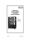
ROUND FRONT
SNACK VENDING MACHINE
SERVICE MANUAL
AMBIENT & CHILLED
GVC1 CONTROLLER
Models:
3 Wide Ambient 3503/3503A
4 Wide Ambient 3504/3504A
INTRODUCTION
This manual contains instructions, service and installation guidelines for the Round
Front Snack product line. All Round Front Snack models are equipped with an
electronic control system. All programming of vend the vend functions, pricing and
features are done at the controller Changes can be made without any additional
accessories or remote parts. Selections can be priced individually from $.05 to
$99.95 in five cent increments (US currency). When adapted to accept international
or foreign currency, the maximum vend price will be 255 times the smallest
denomination of coin being accepted. Cash accountability records Total Cash
transactions and Total Vend cycles performed by the vending machine. Information
for individual selections, complete rows or total machine can be compiled and used
for inventory and ordering records. Electrical malfunctions are recorded and
displayed when the machine is placed in Service Mode. Non-functional motors or
selections are indicated. Each selection has an individual motor. Functional selections
will continue to operate if other motors become non-functional. The vending
sequence is “first-in, first-out” for each selection, eliminating the need for stock
rotation to maintain fresh products in the vending area. The temperature is
controlled electronically on models equipped with Chiller Option. The iVend™ Optical
Sensing Option assures that the customer receives a product or get their money
back. Read this manual thoroughly. Become familiar with the machine’s components
and features. The initial set-up of a vending machine is a very important step of
insuring that the equipment operates in a trouble-free manner. Follow the
instructions for the initial installation of the machine to avoid service problems and
minimize set-up time. Access to the service area of this machine should only be
permitted to individuals having knowledge and practical experience of the machine,
in particular as far as safety and hygiene are concerned.
UNPACKING
This machine was thoroughly inspected before leaving the factory and the delivering
carrier has accepted this vending machine as their responsibility. Note any damage
or irregularities at the time of delivery and report them to the carrier. Request a
written inspection report from the claims inspector to file any claim for damage. File
the claim with the carrier (not the manufacturer) within 15 days after receipt of the
machine. Carefully remove the outside packing material so as not to damage the
finish or exterior of the machine. Inspect the machine for concealed shipping
damage. Report any damage hidden by the shipping material directly to the
delivering carrier on a hidden damage report.
NOTE: If the power supply cord is damaged, it must be replaced by the
manufacturer, its service agent or similarly qualified individual in order to
avoid hazard.
Remove the “Knock-A-Way support by placing a 2x6 under the vending machine. Insert
a large screwdriver or prying tool into the groove and split it in two. Turn the leveling
screws as far as possible. See FIGURE 1.
INSTALLATION
Position the vending machine in its place of operation no further than nine (9) feet
from the power outlet or receptacle and check that the door will open fully without
interference. Leave at least six (6) inches of space between the back of the machine
and any wall or obstruction for proper air circulation. Level the vending machine,
making sure all levelers are touching the floor. The vending machine must be level
for proper operation and acceptance of coins through the coin changer. Retrieve the
keys to the vending machine from the coin return cup. Open outer door and remove
all internal packing material. Consult local, state and federal codes and regulations
before installation of the vending machine.
GROUNDING (EARTHING) & ELECTRICAL
Refer to the Safety Manual and Installation Guidelines manual (PIN 4206816) that
shipped in the service package with your machine. Before connecting the vending
machine, the integrity of the main electrical supply must be checked for correct
polarity, presence of ground (earth) and correct voltage. These checks should be
repeated at six (6) month intervals with the routine safety electrical testing of the
vending machine itself. If the receptacle is not properly grounded or polarized, you
should contact a licensed electrician to correctly polarize and/or ground the
receptacle to ensure safe operation. A noise suppressor has been installed in this
machine to compensate for any mains signal noise that could interfere with the
normal operation of the controller. For proper operation of any equipment utilizing
electronically controlled components, the equipment should be placed on an isolated
or dedicated noise free circuit, properly polarized and grounded. Refer to Electrical
Specifications on this sheet to determine circuit amperage and protection.
LOADING PRODUCTS
To load products, lift the tray slightly and pull forward until the tray stops. The
uppermost trays tilt for easier loading. Load product from front to back making sure
all items fit freely between the augers. Do no attempt to force oversize items or
packages into the spaces. Do not skip a space. Place the product on the bottom of
the compartment on the product augers with the label facing the front of the
machine for easy identification by the customer. See FIGURE 2.
The size of the item being vending vended must be larger than the diameter of the
auger being used to vend properly. Undersize items could cause vend problems. If
the product does not fit the auger properly, use a different pitched auger. See Table
I for augers available from your distributor or service entity.
TRAY ADJUSTMENTS
By re-timing the augers, difficult to vend items can be dispensed more dependably.
By altering tray spacing, larger items can be vended. By changing the tray
configuration, different product mixes can be accommodated.
AUGER TIMING
Each auger can be rotated in 20 (degree) increments for a different drop off point.
Most items can be vended successfully when the auger end is positioned at the 6
o’clock position.
To change the auger end position:
1. Remove the motor cover. See FIGURE 3.
2. Raise the motor slightly and pull forward on the auger until it separates from the
motor.
3. Rotate the auger to the desired position and re insert the auger coupling into the
motor.
4. Make sure the auger coupling is seated over the vertical rail or retaining rib on the
tray.
5. Replace the motor cover making sure it is securely tightened.
TRAY SPACING
The trays can be adjusted up or down in one inch increments to provide additional
headroom for vending taller products. When increasing the height in one area, the
same amount of room will be lost at the tray above or below the one being adjusted.
3 WIDE & 4 WIDE TRAY SPACING ADJUSTMENTS
1. Pull out the tray to be adjusted until it stops.
2. Disengage the tray harness from its snap-open harness clamp on the right side
wall.
3. Disconnect the tray plug from its receptacle on the right side wall.
4. Lift up on the front of the tray and pull slightly approximately 1/2 inch (1 cm)
forward to clear the tray stop.
5. Lift up on the rear of the tray and remove it from the vending machine.
6. Disengage both left and right tray rails from their corresponding slots on the left
and right side walls by pulling inward on the bottom front of each rail and lifting its
flange out of the slot.
7. Pull each rail forward to disengage its rear tabs from the hole in the rear wall.
8. Relocate both left and right rails by reversing steps 6 and 7.
9. Replace the tray by placing its rear rollers on the left and right rails and lift up on
the front of the tray as it is pressed back.
10. Install the tray plug into its receptacle on the right side wall.
11. Reengage the tray harness into its harness clamp and snap the clamp closed.
12. Test vend the tray in its new position to assure that the tray plug is properly
seated.
5 WIDE TRAY SPACING ADJUSTMENTS
1. Pull out the tray to be adjusted until it stops.
2. Locate the harness clamp on the right side wall. See FIGURE 4.
3. Open the harness clamp by pressing up on the tab.
4. Unplug the “Double D” tray plug from its receptacle on the right side wall.
5. Lift up on the front of the tray and pull slightly approximately 1/2 inch (1.3 cm)
forward to clear the tray stop.
6. Locate the release lever on the left and right tray rails. See FIGURE 4. Swing
levers all the way up to
7. Lift up on the rear of the tray and remove it from the vending machine.
8. Relocate both left and right tray rails from the left and right side walls.
a. Remove tray mounting screws.
b. Pull each rail forward to disengage its rear tab from the hole in the rear wall. See
FIGURE 5.
9. Relocate both left and right rails by reversing step 8. Rails must be level from
front to back and right to left.
10. Replace the tray by placing its rear rollers on the left and right rails and lifting up
on the front of the tray as you push it back.
11. Swing the tray release levers all the way down.
12. Install the tray plug into its receptacle on the right side wall.
13. Reengage the tray harness into its harness clamp and snap the clamp closed.
14. Test vend the tray in its new position to assure that the tray plug is properly
seated.
CANDY TO SNACK
To change the tray configuration, order a conversion kit. See the Parts Ordering
Procedure section in this document.
1. Order the conversion kit from your local distributor or service entity.
2. Unplug and remove the tray assembly from the vending machine. Place the tray
harness in the tray before removal.
3. Remove the motor cover by pulling up on the front edge of the cover to clear the
stop and then pull forward on the cover.
4. Remove existing ray divider and discard.
5. Remove existing auger assemblies and discard.
6. Remove the existing “even” numbered motor. This motor will not be needed.
7. Tape or secure the terminals removed from the motor out of your way.
8. Move the “odd” numbered motor to the center slot of the compartment.
9. Install the auger retainer furnished as part of the conversion kit.
10. Install the auger assembly furnished as part of the conversion kit, making sure
the motor coupling properly engages the motor and is securely snapped over the
vertical rail or retaining rig on the tray.
11. Re-assemble the motor cover removed in step 3.
12. Replace the tray assembly into the vending machine making sure that the tray is
properly located and latched and connect the tray harness.
13. Set the selection to the desired vend price and adjust the price scroll to the same
price. In large item selections, the selection numbers will be the “odd” numbers. For
example, selections 23 and 24 are converted to a single selection, 23.
14. Test vend the converted selection for proper operation and price settings.
SNACK TO CANDY
To change the tray configuration, order a conversion kit. See Parts Ordering
Procedure section of this manual.
1. Order the conversion kit from your local distributor or service entity.
2. Unplug and remove the tray assembly from the vending machine. Place the tray
harness in the tray before removal.
3. Remove the motor cover by pulling up on front edge of the cover to clear the stop
and then pull forward on cover.
4. Remove the existing auger assembly and discard.
5. Remove the auger retainer and discard.
6. Move motor from the center slot to the left slot in the compartment.
7. Add the new motor furnished as part of the conversion kit in the right hand slot of
the compartment.
8. Properly wire the motor and switch. Refer to the “Schematic” section for wire
colors and locations.
9. Add the divider furnished as part of the conversion kit.
10. Install new auger assemblies furnished as part of the conversion kit, making sure
the motor couplings properly engage with the motor and are securely snapped over
the vertical rail or retaining rib on the tray.
11. Re-assemble the motor cover removed in step 3.
12. Replace the tray assembly into the vending machine making sure that the tray is
properly located and latched and connect the tray harness.
13. Set the selections to the desired vend price and adjust the price scrolls to agree.
14. Test vend the converted selections for proper operation and price settings.
CONTROLLER FUNCTIONS
This vending machine is equipped with a GVCI Controller
SALES MODE
The machine automatically defaults to Sales Mode after it is turned on. The vending
machine accepts deposits, pays out change and dispenses product to the customer.
DISPLAY CREDIT
If credit has not been established and a selection is made, then the price for that
selection is displayed briefly. When money or credit is accepted, then the amount of
credit is displayed. If the payout tubes in the coin mechanism are below the low-level
sensors, the indicator light “USE EXACT CHANGE” will light up.
MAKE SELECTION
If a selection is made and the accumulated credit is greater than or equal to the
price of the selection, then a vend attempt will take place. If credit is less than the
selection price, the price is displayed and will flash.
VEND CYCLE
If the machine is equipped with the iVend™ Optical Sensor Option, then all selections
have been assigned at the factory for optical sensing. These machines will have an
associated vend operation that differs from the normal vend operation. At the start
of a vend, the iVend™ Optical Sensor will be checked for blockage. If iVend™
sensors are blocked or if iVend™ Option is not present - then the normal homeswitch- vend cycle will be used and the optical sensors are ignored. Both the vend
motor and a vend timer are started.
• The selection motor rotates to the home-switch position.
• If there is a home-switch signal, then the vend is considered successful.
• If there is no home-switch signal and the vend timer has expired, then the vend
failed. The vend motor is shut down and “MAKE ANOTHER SELECTION” indicator light
is turned on. The customer can press selection buttons to activate this or another
motor or they can press the coin return button. Force Vend is overridden.
If iVend™ sensors are not blocked - then the iVend™ Optical Sensors are used. The
vend motor and a vend timer are started.
• The selection motor rotates to the home-switch position.
• If a product is detected during this time period, then the vend is considered
successful.
• If after reaching the home-switch position and a product is not detected, then the
vend motor will pause while the controller continues to monitor the optical sensor for
the product delivery.
• If a product is detected during this pause, then the vend is considered successful.
• If a product is not detected, then the controller initiates a second vend cycle and
vend timer while continuing to monitor the optical sensor.
• If a product is detected during the second vend cycle, the motor is stopped
immediately. The vend is considered successful.
• If a product is not detected and the motor reaches the home-switch position or if
the vend timer runs out, then the vend has failed or the selection is sold out. Such a
state will turn on the “MAKE ANOTHER SELECTION” indicator light. The amount of
credit is displayed. The customer can press selection buttons to activate this or
another motor or they can press the coin return button.
CREDIT & COUNTERS
After a successful vend, the amount of remaining credit is displayed until all coinage
is paid back. The total non-resettable vend count is incremented by one (1) and the
total non-resettable cash value is incremented by the price of the vended selection.
The counter rollovers occur at 999,999 and $999,999.99 respectively. The resettable vend count is incremented by one. The re-settable total cash value is
incremented by the price of the vended selection. If never reset, the counter
rollovers occur at 999,999 and $999,999.99 respectively. Test vends are not
included in the counter totals.
SERVICE MODE
The Service Mode is used to access the programming features of the controller: set
price, test vend, retrieve accounting information or set custom program settings. If
credit exists when entering the Service Mode, it will be restored when the machine is
return to Sales Mode.
SERVICE MODE BUTTON
The Service Mode Button is located near the top right corner of the controller cover.
Press the button to access the Service Mode programming features. Press the button
again to exit and return to Sales Mode. If no key is pressed within 60 seconds while
in Service Mode, then the controller automatically exits to the Sales Mode.
KEYPAD
While in Service Mode, the keypad is used to navigate between the menu features
and is also used as an input device for keying in numerical values as required by the
controller program.
DISPLAY
Watch the display after pressing the Service Mode Button and/or keypad buttons.
PROGRAMMING
Refer to the basic programming steps (on back page) or on the control cover label.
Press the Service Mode Button, watch the Display and use the Keypad.
CHILLER OPTION
OPERATION
To prevent damage to the refrigeration unit when it is turned off or the power
interrupted, the refrigeration unit will not restart for at least three minutes
regardless of the temperature. When the temperature is above the cut-in
temperature programmed, the unit is turned on. When the refrigeration unit reaches
the cut-out temperature, it is turned off. If the refrigeration unit runs for more than
two hours without reaching the cut-out temperature, the unit is turned off for the
programmed ten (15) minute defrost time. It will be turned on again automatically.
TROUBLESHOOTING
If the refrigeration unit is turned off or the power is interrupted, the refrigeration unit
will not start for at least three (3) minutes regardless of the temperature. This is
done to prevent damage to the refrigeration unit. If the refrigeration unit is turned
off or the power is interrupted, the refrigeration unit will not start for at least three
(3) minutes regardless of the temperature. This is done to prevent damage to the
refrigeration unit. Know and understand how the unit operates. Units may vary, but
the operation is basically the same. Never guess at the problem. Find the symptom
before attempting any repair.
NOTE: Most refrigeration problems are electrical.
The sealed hermetic system should not be worked on outside the Factory Service
Center. There are three (3) things that can go wrong with a sealed system and
should be repaired only at the Factory Service Center. These are:
1. Low Charge - usually caused by leaks. Look for oil around seals and welds. Unit
will not cool properly. The capillary tube is frosted before it enters the evaporator
inlet tube.
2. Restriction in System (unit frosts, then melts) - not cooling properly.
3. Bad valves - unit does not cool properly - noisy compressor.
CAUTION:
Breaking the refrigerant joints or seals on the system voids the unit warranty.
Failure to keep the condenser coil clean and free of dirt and dust and other
similar debris voids the unit warranty.
TROUBLESHOOTING CIRCUITS WITH MULTI-METER
1. To check the power source, use the voltage section of the Multi-Meter. Should
measure within 5-10% above, 5% below.
2. Check overload. CAUTION: Power must be off and fan circuit open.
Use the resistance section of the Multi- Meter and check terminals I and 3 for
continuity. If no continuity is measured (infinity), then the overload may be tripped.
Wait 10 minutes and try again. If still no continuity, then overload is defective.
3. Check the relay. See FIGURE 8. Unscrew lead terminals and remove relay from
compressor. Keep relay upright. Check terminals I and 5, or L and S with the MultiMeter. Replace relay if continuity exists.
4. Check Temperature sensor with a Multi- Meter.
5. Check compressor windings as shown in FIGURE 8.
6. Check winding resistance with a Multi- Meter. Use RXI scale. If readings are not
within 2 Ohms, the compressor is faulty.
WARNING: Wiring diagrams must be followed as shown. Any mis-wiring can
cause serious electrical hazard and potential damage or rupture component
electrical parts.
PREVENTIVE MAINTENANCE
CAUTION: Always disconnect power source BEFORE cleaning or servicing.
WARNING: This vending machine must not be cleaned with a water jet.
ONCE A MONTH
CLEAN CABINET INTERIOR
Wash with a mild detergent and water, rinse and dry thoroughly. Odors may be
eliminated by including baking soda or ammonia in the cleaning solution. Plastic
parts may be cleaned with a quality plastic cleaner. Remove and clean Condensate
Drain Hose to eliminate any deposits that may restrict condensate water flow. The
vend mechanisms must be kept clean. Any build-up can cause the mechanisms to
malfunction. Do not get the cleaning solution on electrical components. To insure
proper vending keep delivery slide area free of dirt and sticky substances.
CLEAN CABINET EXTERIOR
Wash with a mild detergent and water, rinse and dry thoroughly. Clean occasionally
with a quality car wax. Plastic exterior parts may be cleaned with a quality plastic
cleaner.
EVERY 60 DAYS
CLEAN CHILLER INTAKE SCREEN
Remove screen. Clean dust and debris from screen using a soft bristle brush or a
vacuum cleaner.
EVERY 6 MONTHS
CLEAN CONDENSER COIL & EXHAUST SCREEN
Remove the Cover Assembly and clean the condenser coil of the refrigeration unit
using a soft bristle brush and/or vacuum cleaner Pull the refrigeration unit and clean
the rear exhaust screen of dirt and debris. Do not block the evaporator or any area
of the airflow tilt product or supplies.
PARTS ORDERING PROCEDURE
When ordering parts, include the following:
1. The model and serial numbers of the machine for which the parts are needed.
2. Shipping address.
3. Address where the invoice should be sent.
4. The number of parts required.
5. Always refer to the pertinent parts and/or parts manual for the correct part
number and description of a specific part. When RIGHT or LEFT is used with the
name of a part, it means the person is facing the machine with the door closed,
6. Any special shipping instructions.
7. Carrier desired: air or air special, truck, parcel post or rail.
8. Signature and date.
9. If a purchase order number is used, then be sure it is visible and legible.
Mail your order to:
VendNet
165 North 10th Street
Waukee, IA 50263
USA
All orders are carefully packed and inspected prior to shipment. Damage incurred
during shipment should be reported at once and a claim filed with the terminating
carrier. If you do not have the right parts manual, contact VendNet. If you have any
questions, check out our website www.vendnetusa.com or call VendNet. Ask for the
Parts Department. We will be happy to assist you. Email: [email protected]
BEFORE CALLING FOR SERVICE
Please check the following:
• Does your machine have at least 6 inches (15.2 cm) of clear air space behind it?
• If the power is turned on at the fuse box, is the machine the only thing that does
not work?
• Is the machine plugged directly into the outlet?
WARNING:
DO NOT USE EXTENSION CORDS. Extension cords can cause problems.
• Is the evaporator coil free of dust and dirt?
• Is the condenser coil free of dust and dirt?
• Is the compressor free of dust? A blanket of dust can prevent the compressor from
cooling in between workouts.
• Is the circuit breaker at the fuse box reset?
• Are evaporator fans running? To check if fans are running take a small piece of
paper in front of the evaporator coil and see if the evaporator fans will blow the
paper away.
• Is the condenser fan running? Fold a sheet of 8-1/2” x 11” paper in half. Place the
paper in from of the condenser coils and see if it draws paper to it.
• Is the shelf in front of the evaporator coil clear? No tools, product, or other air
restricting items.
• Is the cold control set as specified? Setting the temperature colder does not
accelerate cooling of product but may and may cause the product to freeze.
The contents of this publication are presented for informational purposes only, and
while every effort has been made to ensure their accuracy, they are not to be
construed as warranties or guarantees, express or implied, regarding the products or
services described herein or their use or applicability. We reserve the right to model
or improve the designs or specifications of such products at any time without notice.


