1
Timer Operation
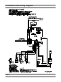
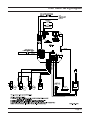
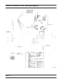
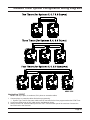
System 7
Alternating (2 Valves)
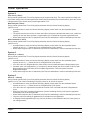
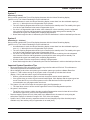
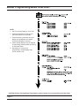
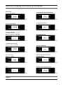
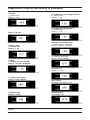
During normal operation the Time of Day display alternates with the Volume Remaining display
(gallons or m3). The Volume Remaining is for the individual unit.
—
—
—
—
As treated water is used, the Volume Remaining display counts down from the calculated capacity to
zero or (----). When this occurs a Regeneration Cycle queues.
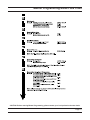
The valve requiring Regeneration sends a lock command to the standby valve. The standby valve goes
to In Service and exhausted valve starts a Regeneration Cycle.
If a valve is in Regeneration and the other valve exhausts its volume remaining, then the exhausted
valve remains In Service with Regeneration queued until the other valve goes into standby. The
exhausted valve goes into standby after completing Regeneration.
Water flow through the valve is indicated by the Flow Dot that flashes in a direct relationship to flow rate.
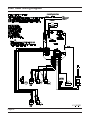
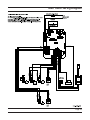
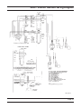
System 9
Alternating (2 – 4 Valves)
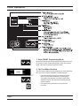
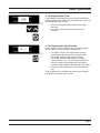
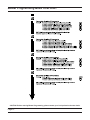
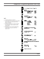
During normal operation the Time of Day display alternates with the Volume Remaining display
(gallons or m3). The Volume Remaining is for the individual unit.
—
—
—
—
—
As treated water is used, the Volume Remaining display counts down from the calculated capacity to
zero or (----). When this occurs a Regeneration Cycle queues.
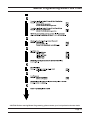
The valve requiring Regeneration sends a lock command to the standby valve. The standby valve goes
to In Service and exhausted valve starts a Regeneration Cycle.
If a valve is in Regeneration and another valve exhausts its volume remaining, then the exhausted
valve remains In Service with Regeneration queued until the other valve goes into standby. The
exhausted valve goes into standby after completing Regeneration.
All units remain In Service except those in standby or Regeneration.
Water flow through the valve is indicated by the Flow Dot that flashes in a direct relationship to flow rate.
Important System Operations Tips
•
•
•
When programming multi-unit systems, program LAg units first and then LEAd unit. This eliminates or
minimizes program and communication errors.
When changing a valve from one system type to another system type, perform a Master Reset first.
System 6, 7 and 9 valves coming out of program mode or on power-up calculate their volume
(display = CALc) and then wait for a good communication signal.
— When a good communication signal is received, the system resume normal operations.
— If the system does not receive a good communication signal, CALc displays and the system goes into
a wait. Press the EC key to force the system out of the wait and resume normal operation. A
communication error may appear after one minute.
• The System 4, 5 and 6 LEAd valve drive sequence going into Regeneration is:
•
— The lower drive moves to off-line and the upper drive moves to first Regeneration position.
All system 7 and 9 valves:
— The off-line valve moves to online, the valve requiring Regeneration moves its lower drive to off-line
and then the upper drive moves to first Regeneration position.
• Reserve capacity–System 4Fd only. After power-up or Master Reset, the reserve is set by using the
safety factor. Reserve is limited to a range of 0% - 50% of the unit capacity.
• System 6 and 7, LEAd units only, respond to remote lock and chemical pump. Also chemical pump is
available only if the auxiliary relay in regeneration is not used [AroF]
Page