1
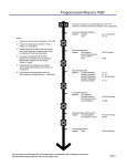
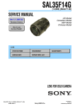
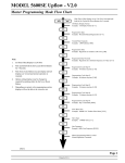
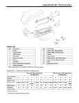
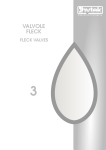
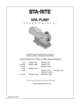
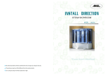
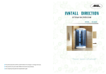
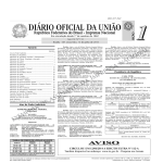
BINRUN Control Valve User Manual BINRUN Control Valve User Manual Table of Contents Function………….………………………………….……………………………….……..01 Features……………………................................................…......................................01 Specifications………………………………….……………………….……………….…...01 Standard Universal Models.…………….……………………………………………..01 Product Models………………….…………..………………….…………………..01 Product Specifications…………………………………..…………………….…....01 Standard Parts…………..….…...……………………..……………………….…..01 Optional Parts………………………………………..………………………….…..02 Other Optional Accessories…………………………………………………….…..02 Warning………………..…………………………..…………………………….…..02 Valve Features and Dimensions…..………………………………………………………03 Softener Timer Valve / Filter Valve profile……………….…..………………………..03 Softener Meter Valve rofile……………………………….……………………………..04 Standard Electric Valve profile…………………………….…………………………..05 Electric Flow Meter Valve profile………………………………………………………..06 Water Conditioner Flow Diagrams….……………………….……….………..……….07 Control Start-up Procedures……….…………………………………………………..….09 Mechanical Softener Valve………….…………………………………………………..09 Mechanical Softener Flow Meter Valve………….…………………………………..10 Mechanical Filter Valve.……………..………………………………………..………..11 Electric Valve……..……………....……………………………………………………..12 Service Instructions………………………………………………………………….……15 To Remove Brine Valve, Injectors and Screen..……..……….……………………….15 To Replace Timer………..………….…..………………………………..………...…..16 To Replace Piston Assembly…………..………..……………………………..…...…17 To Replace Seals and Spacers…..…………………………………………….….…..17 To Replace Flow Meter……...……………………………...……………..……….….18 To Replace Meter Cover and/or Impeller.………...………………………..………...19 Troubleshooting…….……………………………………………….…………….………20 Softener Valve…….……………………………………………..……………………….20 Filter Valve…….………………………………………..…………………….…………..21 Pentair Water, 2008 BINRUN Control Valve User Manual Function Widely used in residential Softeners, Filters and other water solution products to perform automatic resin regeneration and filter media backwash. Features ◆ ◆ ◆ ◆ ◆ ◆ Aesthetic Appearance Clear Display Different control mode Reliable performance Manual Function Simple operation Small and Compact Clear display for regeneration and backwash Timer or Metered regeneration Durable and has passed leak test and Quality Checks Regeneration or Backwash can be reset manually Automatic, User-friendly, 7- or 12- day regeneration cycle Specifications ◆ Standard Universal Model Product Models Product Specifications * (14.5 PSI = 0.1MPA) Standard Parts Pentair Water, 2008 | Page 01 BINRUN Control Valve User Manual 1 2 BLFC (Brine Line Flow Control), refill rate for filling brine tank. DLFC (Drain Line Flow Control), backwash and rapid rinse flow rates. Optional Parts NOTE: Due to varying water conditions, tank sizes and water pressures, the above settings should be used only as a guideline. (14.5 PSI = 0.1MPA) 1BLFC (Brine Line Flow Control), refill rate for filling brine tank. 2DLFC (Drain Line Flow Control), backwash and rapid rinse flow rates. Other Optional Accessories Warning Pentair Water, 2008 | Page 02 BINRUN Control Valve User Manual Valve Features and Dimensions ◆ Softener Timer Valve / Filter Valve profile (unit: mm) Pentair Water, 2008 | Page 03 BINRUN Control Valve User Manual ◆ Softener Meter Valve profile (unit: mm) Pentair Water, 2008 | Page 04 BINRUN Control Valve User Manual ◆ Standard Electric Valve profile (unit: mm) Pentair Water, 2008 | Page 05 BINRUN Control Valve User Manual ◆ Electric Flow Meter Valve profile (unit: mm) Pentair Water, 2008 | Page 06 BINRUN Control Valve User Manual Water Conditioner Flow Diagrams 1. SERVICE POSITION 3. BACKWASH POSITION Hard water enters the unit at the valve inlet – flows around the lower piston groove - thru the passage to the top of tank - down thru the resin and enters the distributor as conditioned water. The conditioned water flows up thru the center tube to the valve outlet. Hard water enters the unit at the valve inlet – flows around the lower piston groove and lower piston land - down thru the center tube and out the distributor – up thru the resin - thru the top of tank passage – around the upper piston groove and out the drain line. 2. PRELIMINARY RINSE POSITION 4. BRINE POSITION Hard water enters the unit at the valve inlet - flows around the lower piston groove - down thru the top of tank passage - downward thru the resin - up the distributor tube - thru the center hole in the piston - over the top edge of the piston and out the drain line. Hard water enters the unit at the valve inlet - flows around the lower piston groove - thru the injector nozzle and orifice to draw brine from the brine tank. The brine flows down thru the resin into the distributor - up thru the center tube - thru the center hole in the piston and out the drain line. Pentair Water, 2008 | Page 07 BINRUN Control Valve User Manual Water Conditioner Flow Diagrams 5. SLOW RINSE POSITION 7. SETTLING RINSE POSITION After all the brine has been drawn from the brine tank, hard water continues to enter thru the valve inlet - flows around the lower piston groove – thru the nozzle and orifice - down thru the resin and into the distributor - up thru the center tube thru the center hole in the piston and out the drain line. Hard water enters the unit at the valve inlet – flows around the lower piston groove - down thru the top of tank passage - downward thru the resin up the distributor tube - thru the center hole in the piston - over the top edge of the piston and out the drain line. 6. RAPID RINSE POSITION 8. BRINE TANK FILL POSITION Hard water enters the unit at the valve inlet – flows around the lower piston groove and lower piston land - down thru the center tube and out the distributor – up thru the resin - thru the top of tank passage - around the upper piston groove and out the drain line. Pentair Water, 2008 | Page 08 Hard water enters the unit at the valve inlet - flows around the lower piston groove - thru the injector throat - thru the brine valve and flow control to fill the brine tank. Hard water also flows around the lower piston groove - thru the passage to the top of tank - down thru the resin and enters the distributor as conditioned water. The conditioned water flows up thru the center tube to the valve outlet. BINRUN Control Valve User Manual Control Start-up Procedures ◆ Mechanical Softener Valve Manually index the softener control into the service position and let water flow into the resin tank. When the water flow stops, open a softened water tap until all air is released from the lines, then close the tap. 1. Manually index the control to the backwash position and allow water to flow at the drain for 3 or 4 minutes. Note: the various regeneration positions may be dialed manually by turning the knob on the front of the control until the indicator shows that the softener is in the desired position. 2. Remove back cover plate. 3. Make sure that the salt dosage is set as recommended by the manufacturer. If necessary, set salt in accordance with the setting instruction sheet. Manually index the control to the brine fill position and allow the brine tank to fill to the top of the air check. 4. Manually index the control to the brine draw position and allow the control to draw water from the brine tank until it stops. 5. Plug in the electrical cord and look in the sight hole in the back of the motor to see that it is running. Set the days that regeneration is to occur by sliding tabs on skipper wheel outward to expose trip fingers. Each tab is one day. Finger at red pointer is tonight. Moving clockwise from red pointer, extend or retract fingers to obtain the desired regeneration schedule. 6. Manually advance the control to the beginning of the brine fill position; and allow the control to return to the service position automatically. 7. Fill the brine tank with salt. 8. Replace back cover on the control 9. Make sure that any by-pass valve/line is left in the normal service position. Pentair Water, 2008 | Page 09 BINRUN Control Valve User Manual ◆ Mechanical Softener Flow Meter Valve The water softener should be installed with the inlet, outlet and drain connections made in accordance with manufacturer’s recommendations and to meet applicable plumbing codes. 1. Manually index the softener control into the service position and let water flow into the resin tank. When the water flow stops, open a softened water tap until all air is released from the lines, then close the tap. NOTE: The various regeneration positions may be dialed manually by turning the knob on the front of the control until the indicator shows that the softener is in the desired position. 2. Set water usage program wheel using any one of the following procedures: Typical Residential Application 3. To program, just set the time, set the hardness and it automatically monitors system needs and regenerates only when necessary. To set time of day press red time set button and turn 24 hour gear until present time of day is at “time of day”. Set program wheel by lifting the “people” dial and rotating it so that the number of people in the household is aligned with the household grains per gallon water hardness. Release the dial and check for firm engagement at setting. (This method will provide reserve capacity based on 75 gallons per person.) Optional Programming Procedures 4. Calculate the gallon capacity of the system, subtract the necessary reserve requirement and set the gallons available at the small white dot on program wheel gear. Note, drawing shows 850 gallon setting. The capacity (gallons) arrow denotes remaining gallons exclusive of fixed reserve. 5. Rotate the program wheel counterclockwise until it stops at regeneration position. 6. Manually index the control to the backwash position and allow water to flow at the drainfor 3 or 4 minutes. 7. Remove back cover plate. 8. Make sure than the salt dosage is set as recommended by the manufacturer. Manually index the control to the brine fill position and allow the brine tank to fill to the top of the air check. Pentair Water, 2008 | Page 10 BINRUN Control Valve User Manual 9. Manually index the control to the brine rinse position and allow the control to draw water from the brine tank until it stops. 10. Plug in the electrical cord and look in the sight hole in the back of the motor to see that it is running. 11. Manually advance the control to the beginning of the brine fill position and allow the control to return to the service position automatically. 12. Fill the brine tank with salt. 13. Replace back cover on the control. Be sure cable is not pinched between cover and housing. 14. Make sure that any by-pass valve/line is left in the normal service position. ◆ Mechanical Filter Valve The filter should be installed with the inlet, outlet, and drain connections made in accordance with the manufacturer’s recommendations and to meet applicable plumbing codes. BEFORE PLUGGING THE UNIT IN 1. Open a treated water tap down stream of the filter. 2. Manually index the filter to the service position and allow the mineral tank to fill by slowly opening the main water supply valve. (any by pass should be in the service position) NOTE: The water flowing from the down stream tap will be cloudy and/or contain media fines as well as air. Allow water to run until it appears clean and free of air. 3. When a steady clean flow appears at the tap, close the tap and the main water supply valve and allow the filter media bed to settle 15 - 20minutes. 4. Manually index the filter to the backwash position. Pentair Water, 2008 | Page 11 BINRUN Control Valve User Manual 6. Continue to open the water supply valve until it is completely open. Allow water to flow at the drain until all media fines are washed out of the filter. 7. Manually index the filter to the service position, and again open the down stream tap. Check to be sure that the water flows clear. If necessary allow water to flow until all media fines are gone. If the tap is equipped with an aerator check that it is not plugged with media fines and pipe scale. 8. Plug in the electrical cord and look in the sight hole on the back of the timer motor to ensure that it is running. Set the days backwashing is to occur by sliding tabs on the skipper wheel outward to expose trip fingers. Each tab is one day. Finger at red pointer is tonight. Moving clockwise from red pointer, extend or retract fingers to obtain the desired backwash schedule. 9. Set time of day by depressing red button and spin the 24 hr gear until the present time of day is visible above the time of day arrow. ◆ Electric Valve The filter should be installed with the inlet, outlet, and drain connections made in accordance with the manufacturer’s recommendations and to meet applicable plumbing codes. Entering Master Programming Mode With Time of Day Display set to 1201 PM, push and hold for 5 seconds both the Set Up and Down Buttons. The Program Indicator will turn on to signal that this mode is entered. In this mode all possible option settings may be viewed. 1. US/Metric Display Format (U) Depress the Extra Cycle Button. This display is used to set the desired display format. This option setting is identified by the letter U in the first digit. There are two possible settings: US Format uses gallons for volume with a 12 hour timekeeping format. Regeneration timing in minutes. Example - [U--1] Metric Format uses liters for volume with a 24 hour timekeeping format. Regeneration timing in tenths of minutes. Example - [U--2] Pentair Water, 2008 | Page 12 BINRUN Control Valve User Manual Cubic Meter Format uses m3 for volume with a 24 hour timekeeping format. Regeneration timing in tenths of minutes. Example - [U--4] The Set UP and Set DOWN Buttons will adjust this value. 2. Regeneration Type (7) Depress the Extra Cycle Button. This display is used to set the Regeneration Type. This option setting is identified by the number 7 in the first digit. There are 3 possible settings: Timeclock Delayed. The control will determine that regeneration is required when the set Regeneration Time has been reached. The Regeneration Day Override setting will determine which days a regeneration cycle will be initiated. Example - [7--1] Meter Immediate. The control will determine that regeneration is required when the available volume of softened water drops to or below zero. Regeneration to begin immediately. Example - [7--2] Meter Delayed. The control will determine that a regeneration is required when the available volume of softened water drops to or below zero. Regeneration is to begin immediately at the set Regeneration Time. Example - [7--3] The Set UP and Set DOWN Buttons will adjust this value. 3. Treated Water Capacity (No Display Code) Depress the Extra Cycle Button. This display is used to set the amount of treated water (gallons/liters) that can be produced by the unit before a regeneration cycle is required. With Meter Delayed Regeneration Type set, it will be up to the programmer to determine a reserve capacity and subtract that value from the calculated full capacity of the unit. This display will not be viewed with Timeclock Regeneration Type set. Example: Regenerate every 700 gallons, liters, or m3 - [700] The Set UP and Set DOWN Buttons will adjust this value. 4. Regeneration Time (No display Code) Depress the Extra Cycle Button. The next display viewed is the option setting for Regeneration Time. It is identified by a non-flashing colon between two sets of numbers. Set the desired time of day that a regeneration may occur, if required. This display will not be viewed with Meter Immediate Regeneration Type set. Example: 2 o’clock A.M. regeneration time - [2:00] (A.M. Indicator Dot On) The Set UP and Set DOWN Buttons will adjust this value. 5. Regeneration Day Override (A) Depress the Extra Cycle Button. This display is used to set the maximum amount of time (in days) the unit can be in service without a regeneration. This option setting is identified by the letter ‘A’ in the first digit. With Meter Immediate Regeneration Type selected, regeneration will begin at the same point in time some amount of days ago when the last regeneration cycle was initiated. With Timeclock or Meter Delayed Regeneration Types selected, regeneration begins at the set Regeneration Time. An OFF setting will cancel this feature with all regeneration Types except Timeclock Regeneration were it must be used. Examples: Override every 7 days -[A--7] Pentair Water, 2008 | Page 13 BINRUN Control Valve User Manual Cancel setting - [AOFF] (Meter Immediate or Delayed Regeneration Types Only) The Set UP and Set DOWN Buttons will adjust this value. 6. Regeneration Cycle Step Programming (1) (2) (3) (4) (5) (6) Depress the Extra Cycle Button. The next 2-4 displays viewed are part of a series of option settings used to program the Regeneration Cycle. Up to 4 steps can be programmed. Each display is used to set the duration time in minutes (or tenths of minutes - Metric) of that specific step in a regeneration cycle. A step # will turn on for the regeneration cycle step being programmed. Regeneration steps are skipped by setting the display to 0 and regeneration ended by setting the step # after the last active step to OFF, as shown below: Examples: Regeneration Cycle Step #1 - 8 minutes - [1--8] Regeneration Cycle Step #3 - skipped - [3--0] Examples: Regeneration Cycle Step #4 - cancelled- [4OFF] Regeneration Cycle Step #4 - 8.5 minutes - [4-8.5] (Metric Format) Depress the Extra Cycle Button once per display to advance through Regeneration Cycle Step Programming. The 5600SE control has a separate brine tank fill cycle. Your desired salt setting must be calculated, using the blue (.25 gpm) or black (.5 gpm) rate of refill (in gpm) times your timer setting. Then using one gallon of fresh water dissolving approximately 3 lbs. of salt, calculate your refill time. Example: lbs. salt 3 | B.L.F.C. Size = refill time in minutes, 10 lbs. salt |3 | .25 = 13.3 minute refill The Set UP and Set DOWN Buttons will adjust these values. 7. Flow Meter Size (F) Depress the Extra Cycle Button. The next display is used to set the flowmeter size. This option setting is identified by the letter F in the first digit. In this display set the proper amount of pulses generated by the flow meter for each gallon or liter of water flow. This setting will not be viewed with Timeclock Regeneration Type selected. Examples: [FI33] 3/4″ Turbine Flow Meter (US Format) [F35.I] 3/4″ Turbine Flow Meter (Metric Format) The Set UP and Set DOWN Buttons will adjust this value. 8. Valve Type (o) Depress the Extra Cycle Button. This display is used to set the type of valve used with the control. This option setting is identified by the letter o in the first digit. There are two possible selections with #1 being the required setting: Examples: [o--1] 5600SE Valve Operation. [o--2] Option Not Typically Used. The Set UP and Set DOWN Buttons will adjust this value. 9. Line Frequency (LF) Depress the Extra Cycle Button. This display is used to set the frequency of the power applied to the control. When properly set, all timekeeping functions will remain accurate. This option setting is identified by the letter o in the first digit. There are two possible selections. Examples: [LF50] 50Hz Line Frequency Operation. [LF60] 60Hz Line Frequency Operation. The Set UP and Set DOWN Buttons will adjust this value. Pentair Water, 2008 | Page 14 BINRUN Control Valve User Manual Exiting This Option Setting Level Push the Extra Cycle Button once per display until all have been viewed. The Program Mode will be exited and normal operation resumed. Resetting Permanent Programming Memory Push and hold the Set Up and Down Buttons for 25 seconds or until the Time Of Day Display resets to 12:00 P.M. All option settings will then reset to default values. Control programming will then have to be reset as necessary. Service Instructions A. TO REMOVE TIME BRINE VALVE, INJECTORS, AND SCREEN 1. Unplug electrical cord from outlet. 2. Turn off water supply to conditioner: a. If the conditioner installation has a “three valve” by-pass system, first open the valve in the by pass line, then close the valves at the conditioner inlet and outlet. b. If the conditioner has an integral by-pass valve, put it in the by-pass position. c. If there is only a shut-off valve near the conditioner inlet, close it. 3. Relieve water pressure in the conditioner by putting the control in the backwash position momentarily. Return the control to the service position. 4. Disconnect brine tube and drain line connections at the injector body. 5. Remove the two injector body mounting screws. The injector and brine module can now be removed from the control valve. Remove and discard valve body O-rings 6a. To Replace Brine Valve 1. Pull brine valve from injector body, also remove & discard O-ring at bottom of brine valve hole. 2. Apply silicone lubricant to new O-ring and reinstall at bottom of brine valve hole. 3. Apply silicone lubricant to O- ring on new valve assembly and press into brine valve hole, shoulder on bushing should be flush with injector body. 6b. To replace injectors and screen. 1. Remove injector cap and screen, discard O-ring Unscrew injector nozzle and throat from injector body. 2. Screw in new injector throat and nozzle, be sure they are seated tightly. Install a new screen. 3. Apply silicone lubricant to new “O” ring and install around oval extension on injector cap. 7. Apply silicone lubricant to three new O-rings and install over three bosses on injector body. 8. Insert screws with washers thru injector cap and injector. Place this assembly thru hole in timer housing and into mating holes in the valve body. Tighten screws. (Be sure to reinstall brass spacers with injector on model 4600 valve.) Pentair Water, 2008 | Page 15 BINRUN Control Valve User Manual 9. Reconnect brine tube and drain line. 10. Return by-pass or inlet valve to normal service position. Water pressure should now be applied to the conditioner, and any by-pass line shut off. 11. Check for leaks at all seal areas. Check drain seal with the control in the backwash position. 12. Plug electrical cord into outlet. 13. Set time of day and cycle the control valve manually to assure proper function. Make sure the control valve is returned to the service position. 14. Make sure there is enough brine in the brine tank. 15. Rotate program wheel counter-clockwise until it stops at regeneration position 16. Start regeneration cycle manually if water is hard. B. TO REPLACE TIMER 1. Unplug electrical cord from outlet. 2. Turn off water supply to conditioner: a. If the conditioner installation has a “three valve” by-pass system, first open the valve in the bypass line, then close the valves at the conditioner inlet and outlet. b. If the conditioner has an integral by-pass valve, put it in the by-pass position. c. If there is only a shut-off valve near the conditioner inlet, close it. 3. Relieve water pressure in the conditioner by putting the control in the backwash position momentarily Return the control to the service position. 4. Pull cable out of meter cover. Remove the control valve back cover. 5. Remove screw and washer at drive yoke. Remove timer mounting screws. The entire timer assembly will now lift off easily. 6. Put new timer on top of valve. Be sure drive pin on main gear engages slot in drive yoke (rotate control knob if necessary). 7. Replace timer mounting screws. Replace screw and washer at drive yoke. 8. Return by-pass or inlet valve to normal service position. Water pressure should now be applied to the conditioner, and any by-pass line shut off. 9. Plug electrical cord into outlet. 10. Set time of day, program wheel, and salt usage. Cycle the control valve manually to assure proper function. Make sure the control valve is returned to the service position. 11. Replace the control valve back cover. Be sure grommet at cable hole is in place. 12. Make sure there is enough brine in the brine tank. 13. Rotate program wheel counter-clockwise until it stops at regeneration position. 14. Start regeneration cycle manually if water is hard. 15. Plug cable into meter cover, rotate cable to align Pentair Water, 2008 | Page 16 BINRUN Control Valve User Manual C. TO REPLACE PISTON ASSEMBLY 1. Unplug electrical cord from outlet. 2. Turn off water supply to conditioner: a. If the conditioner installation has a “three valve” by-pass system, first open the valve in the bypass line, then close the valves at the conditioner inlet and outlet. b. If the conditioner has an integral by-pass valve, put it in the by-pass position. c. If there is only a shut-off valve near the conditioner inlet, close it. 3. Relieve water pressure in the conditioner by putting the control in the backwash position momentarily. Return the control to the service position. 4. Pull cable out of meter cover. Remove the control valve back cover. 5. Remove screw and washer at drive yoke. Remove timer mounting screws. The entire timer assembly will now lift off easily. Remove end plug retainer plate. 6. Pull upward on end of piston yoke until assembly is out of valve. 7. Inspect the inside of the valve to make sure that all spacers and seals are in place, and that there is no foreign matter that would interfere with the valve operation. 8. Take new piston assembly as furnished and push piston into valve by means of the end plug. Twist yoke carefully in a clockwise direction to properly align it with drive gear. Replace end plug retainer plate. 9. Place timer on top of valve. Be sure drive pin on main gear engages slot in drive yoke (rotate control knob if necessary). 10. Replace timer mounting screws. Replace screw and washer at drive yoke. 11. Return by-pass or inlet valve to normal service position. Water pressure should now be applied to the conditioner, and any by-pass line shut off. 12. Plug electrical cord into outlet. 13. Set time of day. Cycle the control valve manually to assure proper function. Make sure the control valve is returned to the service position. 14. Replace the control valve back cover. Be sure grommet at cable hole is in place. 15. Make sure there is enough brine in the brine tank. 16. Rotate program wheel counter-clockwise until it stops at regeneration position. 17. Start regeneration cycle manually if water is hard. 18. Plug cable into meter cover. Rotate cable to align drive flat if necessary. D. TO REPLACE SEALS AND SPACERS 1. Unplug electrical cord from outlet. 2. Turn off water supply to conditioner. a. If the conditioner installation has a “three valve” by-pass system, first open the valve in the bypass line, then close the valves at the conditioner inlet and outlet. b. If the conditioner has an integral by-pass valve, put it in the by-pass position. c. If there is only a shut-off valve near the conditioner inlet, close it. Pentair Water, 2008 | Page 17 BINRUN Control Valve User Manual 3. Relieve water pressure in the conditioner by putting the control in the backwash position momentarily. Return the control to the service position. 4. Pull cable out of meter cover. Remove the control valve back cover. 5. Remove screw and washer at drive yoke. Remove timer mounting screws. The entire timer assembly will now lift off easily. Remove end plug retainer plate. 6. Pull upward on end of piston rod yoke until assembly is out of valve. Remove and replace seats and spacers with fingers. E. TO REPLACE METER 1. Unplug electrical cord from outlet. 2. Turn off water supply to conditioner: a. If the conditioner installation has a “three valve” by-pass system, first open the valve in the by-pass line, then close the valves at the conditioner inlet and outlet. b. If the conditioner has an integral by-pass valve, put it in the by-pass position. c. If there is only a shut-off valve near the conditioner inlet, close it. 3. Relieve water pressure in the conditioner by putting the control in the backwash position momentarily. Return the control to the service position. 4. Pull cable out of meter cover. 5. Remove two screws and clips at by-pass valve or yoke. Pull resin tank away from plumbing connections. 6. Remove two screws and clips at control valve. Pull meter module out of control valve. 7. Apply silicone lubricant to four new O-rings and assemble to four ports on new meter module. 8. Assemble meter to control valve. Note, meter portion of module must be assembled at valve outlet. 9. Attach two clips and screws at control valve. Be sure clip legs are firmly engaged with lugs. 10. Push resin tank back to the plumbing connections and engage meter ports with by-pass valve or yoke. 11. Attach two clips and screws at by-pass valve or yoke. Be sure clip legs are firmly engaged with lugs. 12. Return by-pass or inlet valve to normal service position. Water pressure should now be applied to the conditioner, and any by-pass line shut off. 13. Check for leaks at all seal areas. 14. Plug electrical cord into outlet. 15. Set time of day. Make sure the control valve is in the service position. 16. Rotate program wheel counter-clockwise until it stops at regeneration position. 17. Start regeneration cycle manually if water is hard. 18. Plug cable into meter cover. Rotate cable to align drive flat if necessary. Pentair Water, 2008 | Page 18 BINRUN Control Valve User Manual F. TO REPLACE METER COVER AND/OR IMPELLER 1. Unplug electrical cord from outlet. 2. Turn off water supply to conditioner: a. If the conditioner installation has a “three valve” by-pass system, first open the valve in the bypass line, then close the valves at the conditioner inlet and outlet. b. If the conditioner has an integral by-pass valve, put it in the by-pass position. c. If there is only a shut-off valve near the conditioner inlet, close it. 3. Relieve water pressure in the conditioner by putting the control in the backwash position momentarily. Return the control to the service position. 4. Pull cable out of meter cover. 5. Remove four screws on cover. 6. Lift cover off of meter module, discard O-ring. 7. Remove and inspect impeller for gear or spindle damage, replace if necessary. 8. Apply silicone lubricant to new O-ring and assemble to the smallest diameter on meter cover. 9. Assemble cover to meter module. Be sure impeller spindle enters freely into cover. Press firmly on cover and rotate if necessary to assist in assembly. 10. Replace four screws and tighten. 11. Return by-pass or inlet valve to normal service position. Water pressure should now be applied to the conditioner, and any by-pass line shut off. 12. Check for leaks at all seal areas. 13. Plug electrical cord into outlet. 14. Set time of day. Make sure the control valve is in the service position. 15. Rotate program wheel counter-clockwise until it stops at regeneration position. 16. Start regeneration cycle manually if water is hard. 17. Plug cable into meter cover. Rotate cable to align drive flat if necessary. Pentair Water, 2008 | Page 19 BINRUN Control Valve User Manual Troubleshooting ◆ Softener Valve PROBLEM CAUSE CORRECTION A. Electrical service to unit has been interrupted. A. Assure permanent electrical service (check fuse, plug, pull chain or switch). B. Timer is defective. B. Replace timer. C. Power failure. C. Reset time of day. A. By-pass valve is open. A. Close by-pass valve. B. No salt in brine tank. B. Add salt to brine tank and maintain salt level above water level. C. Injectors or screen plugged. C. Replace injectors and screen. D. Insufficient water flowing into brine tank. D. Check brine tank fill time and clean brine line flow control if plugged. E. Leak at distributor tube. E. Make sure distributor tube is not cracked. Check O-ring and tube pilot. F. Internal valve leak. F. Replace seals and spacers and/or piston. A. Improper salt setting. A. Check salt usage and salt setting. B. Excess water in brine tank. B. See problem No. 7. A. Iron buildup in line to water conditioner. A. Clean line to water conditioner. B. Iron buildup in water conditioner. B. Clean control and add resin cleaner to resin bed. Increase frequency of regeneration. C. Inlet of control plugged due to foreign material broken loose from pipes by recent work done on plumbing system. C. Remove piston & clean control. 5. Loss of resin through drain line. A. Air in water system. A. Assure that well system has proper air eliminator control. Check for dry well condition. 6. Iron In Conditioned Water. A. Fouled resin bed. A. Check backwash, brine draw and brine tank fill, increase frequency of regeneration. Increase backwash time. 7a. Excessive water in brine tank. A. Plugged drain line flow control. A. Clean flow control. 7b. Salt water in service line A. Plugged injector system. A. Clean injector and replace screen. B. Timer not cycling. B. Replace timer. C. Foreign material in brine valve. C. Clean or replace brine valve. D. Foreign material in brine line flow control. D. Clean brine line flow control. A. Drain line flow control is plugged. A. Clean drain line flow control. B. Injector is plugged. B. Clean or replace injectors. C. Injector screen plugged. C. Replace screen. D. Line pressure is too low. D. Increase line pressure. (Line pressure must be at least 20 PSI at all time.) E. Internal control leak. E. Change seals and spacers and/or piston assembly. 1. Softener fails to regenerate 2a. Softener delivers hard water. 3. Unit uses too much salt. 4. Loss of water pressure. 8. Softener fails to draw brine. Pentair Water, 2008 | Page 20 BINRUN Control Valve User Manual Troubleshooting 9. Control cycles continuous A. Faulty timer mechanism A. Replace timer. 10. Drain flows continuously. A. Foreign material in control. A. Remove piston assembly and inspect bore, remove foreign material & check control in various regeneration positions. B. Internal control leak. B. Replace seals and/or piston assembly. C. Control valve jammed in brine or backwash position. C. Replace seals and/or piston assembly. D. Timer motor stopped or jammed D. Replace timer. ◆ Filter Valve PROBLEM CAUSE CORRECTION A. Electrical Service to unit has been interrupted. A. Assure Permanent Electrical Service (Check Fuse, Plug, Pull Chain or Switch). B. Timer is Defective. B. Replace or replace timer. C. Power Failure. C. Reset time of Day. A. By-pass valve is open. A. Close by-pass valve. B. Excessive water usage. B. Reduce days between backwashing (see timer instructions.) Make sure that there is not a leaking valve in the toilet bowl or sinks. C. Hot water tank rusty. C. Repeated flushing of the hot water tank is required. D. Leak at distributor tube. D. Make sure distributor tube is not cracked. Check O-ring and tube pilot. E. Defective or stripped filter medium bed. E. Replace bed. F. Inadequate backwash flow rate. F. Make sure filter has correct drain flow control. Be sure flow control is not clogged or drain line restricted. Be sure water pressure has not dropped. Increase backwash flow rate according to specifications for your unit. See your dealer for recommendations. A. Iron or turbidity buildup in water filter. A. Reduce days between backwashing so filter backwasher more often. Note: Make sure filter is sized large enough to handle water usage. B. Inlet of control plugged due to foreign material broken loose from pipes by recent work done on plumbing system. B. Remove piston and clean control. 4. Loss of filter medium through drain line. A. Broken or missing top screen. A. Replace top screen, must have . 020˝ wide slots. 5. Drain flows continuously A. Foreign material in control. A. Remove piston assembly and inspect bore, remove foreign material and check control in various cycle position. B. Internal control leak. B. Replace seals and/or piston assembly. C. Control valve jammed in rinse or backwash. C. Replace piston and seals and spacers. (and drive motor if necessary). 1. Filter fails to backwash. 2. Filter “bleeds” iron. 3. Loss of water pressure. Pentair Water, 2008 | Page 21 Pentair Water (Factory) Add.: No. 371, Heshan Road, New District, Suzhou China. 215011 Tel.: 86 512 66617690 Fax.: 86 512 66611178 Website: www.pentairwater.cn Hot line: 800-820-6671 Pentair Water (Office) Add.: 21F. Cloud 9 Plaza, No. 1118, West Yan’an Road, Shanghai, P.R.C.200052 Tel.: 86 21 32114588 Fax.: 86 21 32114580 Website: www.pentairwater.cn Hot line: 800-820-6671