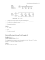
1
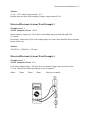
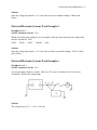
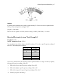
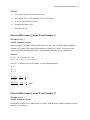
electricalsystem-solutions.doc, p. 1
Name: ___________________________________
Date: _______________
Electrical/Electronic Systems Work Example 1
WorkKey Level: 4
NATEF Automotive Task: VI.D.1
The specs for this alternator reads…puts out 90% of output. The alternator reads 112 amps and
has a rated output of 135 amps.
a.
Is this within specs?
b.
What would the acceptable performance limit have to be in order for this to be an
acceptable reading?
c.
What would the alternator have to produce to be within 90% of the rated output?
Solution
a.
No
b.
The acceptable performance limit would have to be approximately 82.9%.
(112 amps/135 amps = 0.8296296296...)
c.
The alternator would have to produce 121.5 amps.
(135 amps)(90%) = (135 amps)(0.90) = 121.5 amps
Electrical/Electronic Systems Work Example 2
WorkKey Level: 3
NATEF Automotive Tasks: VI.B.1
While testing a battery under no load, the battery has 12 1/4 volts. What is the approximate state
of charge percentage according to the chart below?
Open circuit volts
11.7 volts or less
Percentage of charge
OR
State of charge
0%
12.0 volts
25%
12.2 volts
50%
12.4 volts
75%
12.6 volts or more
100%
electricalsystem-solutions.doc, p. 2
Solution
12 1/4 = 12.25, which is approximately 12.2
Reading from the chart, the percentage of charge is approximately 50%.
Electrical/Electronic Systems Work Example 3
WorkKey Level: 4
NATEF Automotive Tasks: VI.B.2
During a battery capacity test, 50% of the cold cranking amperage should be pulled for
15 seconds.
On a battery with a rating of 700 cold cranking amps, how many amps should be drawn from the
battery for the test?
Solution
(700)(50%) = (700)(0.50) = 350 amps
Electrical/Electronic Systems Work Example 4
WorkKey Level: 3
NATEF Automotive Tasks: VI.A
Look at the voltmeter below. The spec sheet says that the voltage drop must be less than
0.3 volt. Which of the following readings is (are) acceptable?
400mv
300mv
200mv
100mv
None are acceptable.
electricalsystem-solutions.doc, p. 3
Solution
Since the voltage drop must be < 0.3 volts, there are two acceptable readings: 200mv and
100mv.
Electrical/Electronic Systems Work Example 5
WorkKey Level: 3
NATEF Automotive Tasks: VI.A
Which of the following readings is (are) acceptable if the spec sheet states that the voltage drop
must be less than 0.5 volts?
0.500v
0.050v
0.005v
5.000mv
none
Solution
Since the voltage drop must be < 0.5 volts, there are three acceptable readings: 0.050v, 0.005v,
and 5.000mv.
Electrical/Electronic Systems Work Example 6
WorkKey Level: 4
NATEF Automotive Tasks: VI.A
You are checking voltage at a switch. There are 12.2 volts at Terminal A and 11.4 volts at
Terminal B. What is the voltage drop?
Solution
The voltage drop is (12.2 – 11.4) = 0.8 volts.
electricalsystem-solutions.doc, p. 4
Electrical/Electronic Systems Work Example 7
WorkKey Level: 6
NATEF Automotive Tasks: VI.A.12, VI.A.14, VI.H.7
The customer wants to know if he can attach his power booster to his radio circuit. His power
booster uses 200 watts; can he attach it to the radio circuit? Use Ohm’s law to show him if he
can or cannot do this.
Use the drawing and chart to show the customer where he can hook up his power booster. (The
battery voltage is 12.6.)
V = I × R = Ohm’s law
+
Component
Amp
Key On
Radio
6
Key On
Cig lighter
10
Key On
Windows
15
Always
Aux
Open
Solution
First, you must decide how many amps the power booster needs.
200 = 12x
x = 200/12 = 16.6
The booster alone will need 16 2/3 amps.
Next we need to determine how many open amps each component has.
Radio: 10 – 6 = 4 open
Cigarette lighter: 20 – 10 = 10 open
Windows: 20 – 15 = 5 open
Auxiliary: 20 open
The only place the customer can attach his power booster is to put it in auxiliary.
Electrical/Electronic Systems Work Example 8
WorkKey Level: 4
NATEF Automotive Tasks: VI.A.10, VI.A.12
What is the reading on the ohmmeter shown below? Where would the needle point if the switch
was moved to x1000?
electricalsystem-solutions.doc, p. 5
Solution
By looking at the odometer, the reading is approximately 26. Since the switch is pointed to the
x100, you must multiply the reading by 100.
(26)(100) = 2600 ohms
If the switch was pointed to x1000, then the reading would be (2600/1000) = 2.6 ohms.
Electrical/Electronic Systems Work Example 9
WorkKey Level: 4
NATEF Automotive Tasks: VI.B.1
You must determine whether a battery should be replaced. You take a specific gravity reading of
each cell. The readings are as follows:
Cell
Reading
1
1.145
2
1.182
3
1.131
4
1.131
5
1.158
6
1.173
Your service manual states that a battery must be replaced if there is a range of 0.050 (50 points)
in the specific gravity readings of the cell.
a.
What is the lowest specific gravity reading of the cells?
b.
What is the highest specific gravity reading of the cells?
c.
What is the range of the specific gravity readings of the cells?
d.
Should you replace the battery?
electricalsystem-solutions.doc, p. 6
e.
How can you explain the need for a new battery to a customer?
Solution
a.
Reading from the chart, cells 3 and 4 have the lowest reading of 1.131.
b.
Reading from the chart, cell 2 has the highest reading of 1.182.
c.
The range of specific gravity readings is 0.051.
(highest – lowest) = (1.182 – 1.131) = 0.051
d.
Yes
e.
Answers will vary.
Electrical/Electronic Systems Work Example 10
WorkKey Level: 4
NATEF Automotive Tasks: VI.B.1
Open-circuit voltage test (sealed batteries)
Your service manual states that the battery must pass the state-of-charge or open-circuit voltage
test before a capacity test, which provides a realistic determination for battery replacement. If
the battery shows less than 12.2 volts, it should be recharged before the capacity test. If the state
of charge is 75% or more, the battery is considered charged. Using a digital multimeter (DMM)
set on DC volts, you perform an “Open-circuit voltage test” by checking the voltage across the
positive and negative battery terminals. The results of this test can indicate a battery’s state of
charge. You measure 11.8 volts at 80°F on the open-circuit voltage test.
Open-circuit voltage
State of charge at 80°F
12.6 or greater
100%
12.4 to 12.6 volts
70%–100%
12.2 to 12.4 volts
50%–75%
11.7 to 12.0 volts
0%–25%
11.7 or less
0%
a.
What voltage reading indicates a 100% charge?
b.
What does your reading indicate?
c.
What reading indicates a 75% charge?
d.
Should you recharge or replace the battery?
e.
How can you explain the need for a new battery to a customer?
electricalsystem-solutions.doc, p. 7
Solution
a.
12.6 volts or greater (Read from the chart.)
b.
Our reading of 11.8 volts indicates a 0% to 25% charge.
c.
12.4 volts (Read from the chart.)
d.
Recharge the battery first
e.
Answers will vary.
Electrical/Electronic Systems Work Example 11
WorkKey Level: 5
NATEF Automotive Tasks:
When you apply your brake, all three brake lights are dim. The two brake lights each have a
resistance of 2 ohms. The center brake light has a resistance of 4 ohms. Your meter reads
4 ohms at the base of the parallel circuit. Is the reading within the circuit’s parameter?
Solution
Rt = (R1 × R2 × R3)/(R1 + R2 + R3)
Rt = (2 × 2 × 4)/(2 + 2 + 4) = 16/8 = 2
Since Rt = 2 and the meter reads 4 ohms, it is not within parameters.
R1 = 2
R2 = 2
R3 = 4
R1 × R 2
R1 + R 2
=
R EQ × R3
R EQ + R3
2•2
4
= =1
2+2 4
=
1× 4
4
= = 0.8Ω
1+ 4 5
Electrical/Electronic Systems Work Example 12
WorkKey Level: 5
NATEF Automotive Tasks:
On a parallel circuit, R1 is 2 ohms and R2 is 4 ohms. Find the total resistance and total current
draw on a 12-V battery.
electricalsystem-solutions.doc, p. 8
Solution
RT = total resistance in a parallel circuit
R1 = 2 ohms
R2 = 4 ohms
RT = (2·• 4)/(2+4) = 8/6 = 4/3 = 1.3 ohms
1/RT = 3/4
(3/4)·(12/1) = 9 amps
Electrical/Electronic Systems Work Example 13
WorkKey Level: 4
NATEF Automotive Tasks:
The lights are not working in a car and you are testing several electrical components.
When you test the wiring for your headlight the amp meter gives a reading of 2.5 amps.
The headlight has a resistance of 5 Ω.
Is there a problem in the wiring?
Solution
12.6 v/5 ohms = 2.52 amps
No
Electrical/Electronic Systems Work Example 14
WorkKey Level: 4
NATEF Automotive Tasks:
Ohm’s law states that E = I*R where E = voltage, I = amperage, and R = resistance. Find the
resistance if the voltage is 12 and the amperage is 2.
Solution
E = I*R
12 = 2(R)
12/2 = R
6=R
The resistance is 6 ohms.
electricalsystem-solutions.doc, p. 9
Electrical/Electronic Systems Work Example 15
WorkKey Level: 4
NATEF Automotive Tasks:
The reading on the ohmmeter is 0.342 and the switch is on 2k ohms.
a)
What is the reading in ohms?
b) What is the reading in milliohms?
Solution
a)
0.342 ohms × 1000 = 342 Ω
b) 342 ohms × 1000 = 342,000 mΩ or 0.34 KΩ
Electrical/Electronic Systems Work Example 16
WorkKey Level: 3
NATEF Automotive Tasks:
In a series circuit the sum of the resistors equals the total resistance of the circuit.
In a circuit, resistor 1 = 3 ohms and resistor 2 = 8 ohms.
What is the total resistance of the series circuit?
Solution
3 ohms + 8 ohms = 11 ohms total resistance
Electrical/Electronic Systems Work Example 17
WorkKey Level: 5
NATEF Automotive Tasks:
You are helping a buddy install a light bar on his four-wheel-drive truck, which has a 12-volt
battery. It uses four huge spotlights so he can 4 wheel at night. They are hooked up in parallel
and use 1-ohm-resistance bulbs.
He is continually blowing 30-amp fuses!
Does he have a short or is the fuse too small? Oh yeah? Well—prove it!
electricalsystem-solutions.doc, p. 10
1.
Calculate total circuit resistance using the attached diagram. ___________
2.
Use Ohm’s law to figure the current. __________
3.
Determine the problem.
Solution
1.
Rt = 0.25Ω
2.
48 A
3.
The fuse is too small.
Electrical/Electronic Systems Work Example 18
WorkKey Level: 4
NATEF Automotive Tasks: VI.A.8
The voltage drop in an automotive starter relay switch is 0.4 volt. There are 12.7 volts at
terminal “D.” What is the voltage at terminal “E”?
Solution
12.7 volts – 0.4 volt = 12.3 volts
electricalsystem-solutions.doc, p. 11
Electrical/Electronic Systems Work Example 19
WorkKey Level: 6
NATEF Automotive Tasks:
A given V8 will have an ideal current draw of 200 amps. The specs allow for a tolerance of
±10%. Starter circuit resistance is 0.03 and battery voltage is 12.6 V. Will the circuit fall within
specifications?
Solution
Ohm’s law: Volts = Amps × Ohms
A car has 12.6 volts, and the resistance is 0.03 ohm.
Amps = 12.6/0.03 = 420 amps
Since 220 amps is the maximum range, the starter circuit is not within range.