1
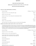
Radiant Flash Service Manual REV: 000 Table Of Contents Introduction 3 Standard Operating Guide 3 Installation 4 External Layout 5-6 Internal Layout 7 Wiring Diagram 8 F.A.Q. Comprehensive Parts List 9 - 12 13 2 Introduction: The Radiant Flash Cure is designed to work with both our Freedom and Javelin series of automatic presses. The Radiant Flash is an In-Head flash alternative to our Flashback unit. The Radiant Flash consumes a print head, is inexpensive to purchase, and is a better alternative to using a manual flash cure unit. This Radiant Flash can be positioned in a portrait or landscape fashion on the press. Standard Operations Guide: The Radiant Flash is installed using the screen clamps on the print arm and can be positioned as desired by the user. Once positioned, the communication wire can be routed to the closest Flashback or to the base of the machine. If ran to a Flashback, you will need to remove the Dummy plug on the back panel of the Flashback and connect the Radiant Flash there. If ran to the base of the machine, the Dummy Plug must be removed and the cable gets plugged in there. The removed Dummy plug will then be installed into the Radiant Flash to complete the connection. At this time, you can plug the main power cable in and you will be ready to turn the machine on. Once turned on, the flash will only heat up if the machine is cycled up and down. When the pallets are down, an internal timer allows the element to heat. If you do not raise the table again within 2 minutes, the flash will time out and turn the power to the flash off, thus cooling the element. To ensure that the flash stays on, you can cycle your shirt boards; this process also helps to heat the pallets prior to printing. Because the Radiant Flash connects directly to the control panel of the press, it turns on and off simultaneously with the press. If the press is left idle for more than 2 minutes, or if you do not raise the table within 2 minutes, as mentioned above, the flash will automatically shut off. These features prevent the flash from being left on accidentally causing a potential fire or to avoid burning or damaging anything. If left idle for more than two minutes and the flash shuts off, just table up and back down and the element will begin to heat again. The element does not take long to get to temperature. On older Freedom and Javelin presses, you may not have the same type of Dummy plug and or communication cable. If so, it will be necessary to use an adapter from the round din to rectangular. Part numbers for these adaptors can be found in the comprehensive parts list at the end of this manual. Features/ Specs: Power Options 220V, Single Phase 50-60Hz at 3015Watts, 14 amps Construction All steel construction Features Large IR heat panel Safety cutoff timer 3 Portrait Installation Landscape Installation 4 External Layout Top View Box Weldment Part A Element Part B Bottom View Screw Box Cover Part C Part D 5 Cord Clamp Cord Clamp Part F Part E Control Panel Power Indicator Lamp Part G On/ Off Switch Dummy Plug Receptacle Part H Part I Duplicate View Heat Indicator Lamp Part G 220V Power Cord Part J Communicator Cable Part K Dummy Plug Part L 6 Internal Layout WARNING! RISK OF ELECTRICAL SHOCK! Turn ALL power to unit OFF before service. All service should be done by or under the supervision of a trained technician Control Box Internals Terminal Block Relay Part M On/ Off Switch Part N Part H Element Part B Duplicate View Dummy Plug Receptacle Part I Timer Part 0 7 Wiring Diagram: 220V Radiant Flash Dryer Shown above, “NEMA 6 - 15P” This plug is standard on all models P/N: 390625 REV:0 8 WARNING! RISK OF ELECTRICAL SHOCK! Turn ALL power to unit OFF before service. All service should be done by or under the supervision of a trained technician FAQ. 1. My Flash Does not Heat up when I turn it on. The radiant flash unit requires a table-up, table-down signal from the press to start the heating process. Check to make sure the flash unit is plugged in. When the unit is powered the light in image 1 will be lit, when the unit is heating the secondary light will turn on. If the unit is still not heating up its time to check the power switch. To test the power coming into the unit use a digital Volt/Ohm meter set the dial to the ACV setting (ACV 200-1000 on a non auto-ranging meter) touch one lead to the marked terminal of the switch in image 2 and the other to the opposite terminal on the switch, it should read 215V - 225V. To test power coming from the switch into the unit use a digital Volt/Ohm meter in the resistance setting (Upside down Omega symbol) With the unit unplugged and the switch in the ON position, touch one lead to the marked terminal of the switch in image 2 and the other lead to the opposite terminal (Image 2).The meter should have a low reading or produce a beep, if the meter reads zero or doesn’t produce a beep the switch will need to be replaced. Image 1 Power Indicator Heat Indicator Image 2 ACV IN ACV OUT 9 2. I’ve got power to the unit and the power switch tested good, but the element still isn't heating up. Then it is now time to test the relay. Using a digital Volt/Ohm meter in the resistance setting (Upside down Omega symbol) remove the wire connectors from the main relay (Image 3) check the resistance across the relay terminals this should be 17-19 Ohms, if the reading is zero replace the relay. With the wires disconnected plug in the flash, using a digital Volt/Ohm meter set the dial to the ACV setting (ACV 200-1000 on a non auto-ranging meter) place one lead on one terminal and the other lead on the opposite terminal. When the machine is tabled up and back down the relay terminals will have 220VAC across them. If there is a reading of zero replace the relay. Image 3 3. My flash isn't heating up and I’ve ruled out all other components except for the element. Then it is now time to test the elements continuity. Using a digital Volt/Ohm meter in the resistance setting (Upside down Omega symbol) remove the wire connectors from the main relay (Image 3) Insert one lead to into one connector and the other lead into other connector (Image 4) The meter should have a low reading or produce a beep, if the meter reads zero or doesn’t produce a beep the element will need to be replaced. Image 4 4. How long does the element stay? The timer is set just under 2 min, this gives about 1 min. 45 sec. for the element to stay on. Anything longer and the element can begin to burn garments (Image 5) Image 5 10 4. How long does the element stay? The timer is set just under 2 min, this gives about 1 min. 45 sec. for the element to stay on. Anything longer and the element can begin to burn garments (Image 5) Image 5 5. How do I test my timer? The timer works off the same signal as the Flashback. When the table raises and lowers, it turns the timer on allowing the element to get hot. When the power is turned off to the machine, the timer will turn off. In order to be reset, the machine will need to be raised and lowered again for the flash to get hot. Image 6 When testing the timer for voltage, when the table is down, the red wire should have a +24VDC. In the table up mode, the blue wire should have a +24VDC. The -24VDC can be picked up on the Black Wire (Image 6) 6. My flash seems to take along time to heat up, how long should it take? It should take just a few minutes to get up to temperature. 7. What is the voltage of the flash? 220 VAC 8. What is the wattage of the flash? 3,015 Watts 9. How hot does the element get? 600 to 700 degrees 11 10. My shirts are not drying. Try lowering the off contact of the element. Turn up the print time 11. My shirts are smoking. Raise the off contact of the element. Turn down the print time if possible. 12. How do I adjust the temperature? There is not a temperature control on the unit. 13. I have an older Freedom/ Javelin, will the Radiant Flash work with my press? Yes, with the use of the adapters shown below as well as in the parts list Image 7 Image 8 12 Comprehensive Parts List. Description Description P/N P/N A. Box Weldment WA-0095 B. Element 20603-1R C. Screw D. Box Cover I-0588 E. Cord Clamp (Big) 76086 F. Cord Clamp (Small) 76028 G. Power/Heater Indicator Lamp 76014 H. On/ Off Switch 76003 I. Dummy Plug Receptacle J. 220V Power Cord K. Communicator Cable w/ plug EA-0005 L. Dummy Plug EA-0007 M. Terminal Block N. Relay 30-1159 O. Timer 30-1255 P. Round Male - Rectangular Female EA-0008 Q. Round Female - Rectangular Male EA-0009 Description Description P/N P/N 41-SEMS-8-10 EA-0006 390974 10-11-023 13