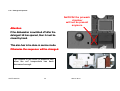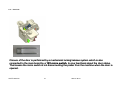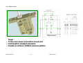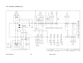
1
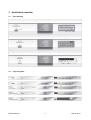
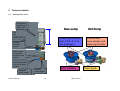
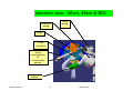
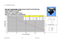
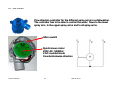
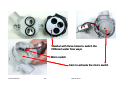
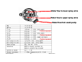
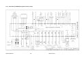
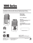
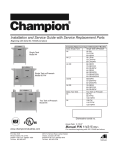
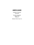
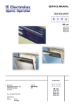
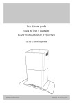
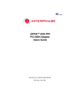
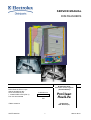
SERVICE MANUAL DISHWASHERS ELECTROLUX ITALY S.p.A. Spares Operations Italy Corso Lino Zanussi, 30 I - 33080 PORCIA /PN (ITALY) Fax +39 0434 394096 Dishwasher with electronic control system (Functionalities) Publication no. 599 72 48-93 EN Edition: 2009/12 SOI/TD 2009/12 ProClean RealLife Production: ZM - Solaro (IT) 1 599 72 48-93 CONTENTS 1 2 3 4 5 6 7 8 9 Purpose of this manual............................................................................................................................3 Precautions..............................................................................................................................................3 Aesthetical overview................................................................................................................................4 3.1 Free Standing .......................................................................................................................................4 3.2 Fully Integrated .....................................................................................................................................4 3.3 Built In...................................................................................................................................................5 Location of LED’s and Push Buttons.......................................................................................................6 4.1 EDW1xxx-2G-UI´s families supported :................................................................................................6 4.2 EDW3000 – UI´s families supported : ..................................................................................................6 Program Reset ........................................................................................................................................7 User Mode Settings.................................................................................................................................7 6.1 Entering the User Mode........................................................................................................................7 6.2 Setting Water Hardness .......................................................................................................................7 6.3 Disable/Enable Rinse Aid Dosing.........................................................................................................8 6.4 Disable/Enable Buzzer .........................................................................................................................8 Service Mode Settings ............................................................................................................................9 7.1 Alarm Code Reading and Single Load Activation ................................................................................9 7.2 LED Test and Reset Alarm Memory.....................................................................................................9 7.3 Line test program..................................................................................................................................9 7.4 Selecting/Deselecting an rinse+ .........................................................................................................10 Alarm Codes..........................................................................................................................................11 8.1 Alarm Management ............................................................................................................................11 8.2 Alarm Code Description......................................................................................................................12 8.2.1 “i10” Code - family : Water Tap Closed .....................................................................................12 8.2.2 “i20” Code - familiy : Draining Problem......................................................................................12 8.2.3 “i30” Codes - family : Aqua Control............................................................................................12 8.2.4 “i40” Code - family : analogue pressure sensor.........................................................................12 8.2.5 “i50” Code - family : Motor Problem...........................................................................................13 8.2.6 “i60” Code - family : Heating Problem........................................................................................13 8.2.7 “i70” Code - family : NTC Problem.............................................................................................14 8.2.8 “i90” Code – family : Configuration problem ..............................................................................14 8.2.9 “iB0” Code - family : Turbidity Sensor Problem .........................................................................14 8.2.10 “iC0” Code - family : Communication Problem ..........................................................................14 8.2.11 “iD0” Code - family : Tacho Problem .........................................................................................14 8.2.12 “iE0” Code - family : flow control position (sprayarm level) .......................................................14 8.2.13 “iF0” Code : Overfilling detected ................................................................................................15 Technical details....................................................................................................................................16 9.1 New hydraulic circuit...........................................................................................................................16 9.2 New components ................................................................................................................................18 9.3 Hydraulic circuit ..................................................................................................................................20 9.4 Washing Pump – Single phase asynchronous motor.........................................................................21 9.5 Washing Pump – 3-phase Inverter motor...........................................................................................22 9.6 Drain Pump.........................................................................................................................................24 9.7 Heating element..................................................................................................................................25 9.8 Analog Pressure switch ......................................................................................................................26 9.9 Flow controller ....................................................................................................................................27 9.10 Detergent dispenser .......................................................................................................................30 9.11 Doorlock .........................................................................................................................................31 9.12 ON/OFF switch...............................................................................................................................32 9.13 Beam-on-Floor ...............................................................................................................................35 9.14 Schematic for EDW1xxx-2G ..........................................................................................................36 9.15 Schematic for EDW3000 (single phase motor)..............................................................................37 9.16 Schematic for EDW3000 (3-phase inverter motor) ........................................................................38 SOI/TD 2009/12 2 599 72 48-93 1 Purpose of this manual The purpose of this Service Manual is to provide Service Engineers with technical information regarding new range of “ProClean/RealLife” dishwashers and to give a description of the alarm codes and service functionality of the EDW1xxx-2G and the EDW3000 family. This Manual describes: • General characteristics • Control panel and programmes • Technical characteristics • Guide to diagnostics For more detailed information regarding the hydraulic circuits and the structural characteristics of the appliances, refer to the Service Manual for presentation of the “ProClean/RealLife” structure. 2 Precautions SOI/TD 2009/12 Electrical appliances must be serviced only by qualified Service Engineers. Always remove the plug from the power socket before touching internal components. 3 599 72 48-93 3 Aesthetical overview 3.1 Free Standing 3.2 Fully Integrated SOI/TD 2009/12 4 599 72 48-93 3.3 Built In SOI/TD 2009/12 5 599 72 48-93 4 Location of LED’s and Push Buttons 4.1 EDW1xxx-2G-UI´s families supported : 4.2 EDW3000 – UI´s families supported : SOI/TD 2009/12 6 599 72 48-93 5 Program Reset “Program Reset” is a special kind of user mode to stop and deselect a running program. By doing this the appliance switch back in state “no program selected, wait for selection”. RESET can only be performed after washing cycle has started On EDW1xxx-2G user interface family : Pressing buttons S2+S3 at least 1sec or as well single button when specified on according PNC by personalisation software On EDW3000 user interface family : Pressing buttons S3+S4 at least 1sec or - as well single button when specified on according PNC by personalisation 1 2 3 4 6 User Mode Settings 6.1 Entering the User Mode Entering this mode is done by pressing simultaneous the two push buttons at least 2sec after switch on the machine and no program selected: on EDW1xxx-2G´s user inetrfaces : pressing buttons S2+S3. on EDW3xxx user interfaces : options menu. User mode is left by switching off the appliance or after a 60sec time out. Activated mode is indicated by flashing all LED’s corresponding to push buttons, which are available in that mode. On lcd´s, user mode is integrated in option settings menu. Example for 3 digits display: 1. 2. 6.2 Setting Water Hardness The range for setting the water hardness is from 1 to 10 (soft to hard). In appliances with 3-digit Display, when entered the user mode, by pressing the push button S1 the actual set water hardness is displayed on the 7-segment display in the way “1L” to “10L”. Pressing the push button S1 increases the hardness setting by one. The actual level is displayed accordingly. To store the adjustment press key S0. SOI/TD 2009/12 7 599 72 48-93 1. 3. 2. 6.3 Disable/Enable Rinse Aid Dosing With the function it is possible to disable the rinse aid dosing. In appliances with 3-digit Display, when entered the user mode, by pressing the push button S2 the actual state is displayed on the 7-segment display “0d” for disabled and “1d” for enabled. To toggle the state of activation the push button S2 is used. The actual level is displayed accordingly. 6.4 Disable/Enable Buzzer With the function it is possible to disable the buzzer as end of cycle indication. In appliances with 3-digit Display, when entered the user mode, by pressing the push button S3 the actual state is displayed on the 7-segment display “0b” for disabled and “1b” for enabled. To toggle the state of activation the push button S3 is used. The actual level is displayed accordingly. SOI/TD 2009/12 8 599 72 48-93 7 Service Mode Settings Only if the appliance is in waiting mode, entering the service mode is done by pressing simultaneous two push buttons, then switching on the machine and wait for 4sec. On EDW1xxx-2G´s user interfaces : Pressing buttons S1+S3. On EDW3xxx connected user interfaces : Pressing buttons S1+S3 (EDW2500) or S3+S4 (EDW2503). Service mode is left by switching off the appliance or after a 60sec time out. Activated mode is indicated by the LEDs related to the buttons S1, S2 and S3. 7.1 Alarm Code Reading and Single Load Activation If entered the service mode, the single load activation is selected by pressing the S1. Each time pressing S1 moves to the next actuator to activate. After controlling the last in list it will switch back to the first. The sequence of the actuators is defined like that: 1. Alarm code 1 2. Alarm code 2 3. Alarm code 3 4. Regeneration valve 5. Drain pump 6. Inlet valve 7. Heating (if the level of water is reached) 8. Circulating with 2800rpm 9. Dispenser 10. Fan If a display is available, the actual test step will be indicated by its number (starting with 4.) 7.2 LED Test and Reset Alarm Memory If entered the service mode, the line test program is selected by pressing the button S2. All indication LED’s are flashing 30sec. Alarm code memory is cleared. 7.3 Line test program If entered the service mode the line test program is selected by pressing the button S3. The line test program starts immediately. SOI/TD 2009/12 9 599 72 48-93 The running line test program is displayed by a flashing LED related to the button S3 and it takes 15 minutes. After finishing the line test the LED related to the button S3 is switched off and the LED end will be activated and the remaining time displays 0 respectively. 15 7.4 Selecting/Deselecting an rinse+ When entered the service, mode by pressing the buttons S1+S2 simultaneously the actual state is displayed. With this setting an additional rinse can be selected. On appliances without displays or with 1-digit displays the actual state is indicated by LED “End”. If on, the function is selected, if off it is deselected. On appliances with a 3 -digit display the actual state is indicated by “E1” if selected and “E0” is deselected. To toggle the program button S1 has to be pressed. E0 SOI/TD 2009/12 E1 10 599 72 48-93 8 Alarm Codes 8.1 Alarm Management In “ProClean/RealLife” appliances the alarm codes are defined in family alarm and actual alarm, displayed as: iXY i = Alarm indication X = Family alarm Y = Actual alarm Attention: Only the family alarm code is displayed to the user. The complete alarm codes will be stored in the three alarm memories of the machine. A new alarm code is stored only if it differs from the last stored code. The three most recent alarm codes can be displayed in the service mode only or by using Sidekick tool. Appliances without time to end display will show the alarms on the flashing End-LED, like in DIVA: i10=1 flash, i50=5 flashes, iB0=11 flashe SOI/TD 2009/12 11 599 72 48-93 8.2 Alarm Code Description 8.2.1 “i10” Code - family : Water Tap Closed 8.2.1.1 “i10” code – during static filling This alarm code is used to display problems with water tap closed at program begin. It is setup to detect problem by static water load. A drain phase is executed before the error is displayed to the user. - Acoustical and optical signalling, depending on variant; program can be restarted - Requested level is not reached within debounce time. - Debounce time starts counting when water inlet valve is opened. - Debounce time is reset when water inlet valve is closed. - Water will be drained out before error condition is displayed to the user - Debounce time : Normal 90sec; Linetest = 30sec (times could be different because defined in washing cycle specification) 8.2.1.2 - “i11” code – during dynamic filling Acoustical and optical signalling depending on variant, program can be restarted Requested level is not reached within debounce time. Debounce time starts counting when water inlet valve is opened. Debounce time is reset when water inlet valve is closed. Debounce time : Normal 120sec; Linetest = 60sec (times could be differ because defined in washing cycles spec.) 8.2.2 - “i20” Code - familiy : Draining Problem Acoustical and optical signalling depending on variant, program can be restarted “Back switch point” of pressure sensor level is not reached within debounce time(level can be different, defined in washing cycle spec.) Debounce time starts counting when drain pump is activated. Debounce time is reset when drain pump has stopped in normal manner. Debounce time : Normal 90sec; Linetest = 60sec - 8.2.3 “i30” Codes - family : Aqua Control 8.2.3.1 “i30” code - Acoustical and optical signalling depending on variant, program resumes automatically when alarm condition not valid. - If alarm occurs, drain pump is being activated. - Debounce time : 10sec 8.2.4 “i40” Code - family : analogue pressure sensor 8.2.4.1 “i41” code - the error is set if no sensor signal is found for more then 1sec or if the signal is out of range - abort program and display error 8.2.4.2 “i42” code - the error is set if the sensor signal is not stable enough for calibration or if the signal is out of range for an empty dishwasher. - the calibration is performed during the running drain pump and shortly after to guarantee that if not tight backflow valve returning water will not corrupt the calibration SOI/TD 2009/12 12 599 72 48-93 8.2.5 “i50” Code - family : Motor Problem 8.2.5.1 - “i51” – code – asynchronous motor Optical signalling depending on variant, program stops. Circulation pump is running without being activated by software, a triac short-cut is assumed Heating will not be switched on If the alarm occurs, filling valve is activated until pressure switch point is reached an program stops Debounce time : 8sec 8.2.5.2 “i52” – code – asynchronous motor – abnormal extra current detected - Alarm will be set when abnormal extra current of about 1.3 amps are detected. 8.2.5.3 “i53” – code – asynchronous motor – over current - Alarm will be set when the max. allowed current will be detected higher than 1.3 A 8.2.5.4 “i54” – code – bldc motor rotor locked - alarm will set when the motor locked condition is detected during start of motor and also during the running motor; - reasons can be dirt, too high load, mechanical problems on impeller 8.2.5.5 “i55” – code – motor control board Vbat over voltage - alarm is set when the Vbat voltage on motor control board will be detected greater the 400Vdc 8.2.5.6 “i56” – code – motor control board Vbat under voltage - alarm is set when the Vbat voltage on motor control board will be detected lower than 255Vdc 8.2.5.7 “i57“ – code – motor control board Vbat voltage plausability - alarm will be set if Vbat is detected higher than 440V or lower than 215V. 8.2.5.8 “i58“ – code – motor plug connection - alarm will be set if motor connection is detected wrong based on motor currents measurements; - debounce is set to 2 sec 8.2.5.9 “i59“ – code – motor control board current read adc - fault - alarm is set if there is detected a fault in the current reading chain on mcb; - it´s verified by the current sum of the three motor phases which should be nearly zero: if the sum is higher than 40mA for longer than 300 msec than the assumption is that something is wrong. 8.2.5.10 “i5A“ – code – over temperature motor windings - internal warning is set when the internal calculations based on the measured currents lets expect that the temperature are out of standard limits (200°C – with 40°C margin due to measurement and calculation tolerances) - the alarm is set if the value is greater than the threshold 178°C. 8.2.6 “i60” Code - family : Heating Problem 8.2.6.1 “i60” – code – heating - Alarm code storing in memory, displayed only in service mode, program continues without activation of heating element. - During heating steps the rising of temperature is monitored, the monitoring is restarted every 3min. - Within these 3 minutes temperature has to rise in minimum about 1°C. 8.2.6.2 “i61” – code – heating over temperature - if water temperature is detected higher than 78°C, cycle is stopped. SOI/TD 2009/12 13 599 72 48-93 8.2.7 “i70” Code - family : NTC Problem 8.2.7.1 “i70” - code - Alarm code storing in memory, displayed only in service mode, program continues without activation of heating element. - Monitoring start immediately after initialisation of the program - NTC voltage has to be in range 0,04 – 4,7V. - Debounce time 10sec 8.2.8 “i90” Code – family : Configuration problem 8.2.8.1 “i91” – code - No program start possible, can be released by switching off and on again - When starting up the content of mcf memory area is validated by processing some checksums. - User interface identification does not fit to main board request. 8.2.8.2 “i92” – code - alarm is set if checksum of .ccf (washing cycle) data is corrupted. 8.2.9 “iB0” Code - family : Turbidity Sensor Problem 8.2.9.1 “iB0” - code – turbidity sensor - Calibration routine has not finished after 15sec. - Program will run with measurement value “dirty” set to yes 8.2.10 “iC0” Code - family : Communication Problem 8.2.10.1 “iC0” – code – user interface communication - failure appears if no user interface is detected in communication system 8.2.10.2 “iC1” – code - hardware level check communication error occurs after 3 telegramms 8.2.10.3 “iC2” – Code - Stop the program. It resumes automatically when alarm condition is not valid. 8.2.10.4 “iC3” – Code – base board vs motor control board communication - start up communication with motor control board for asynchronous motor failed - Acoustical and optical signalling depending on variant; program resumes automatically when alarm condition is not valid. 8.2.11 “iD0” Code - family : Tacho Problem 8.2.11.1 “iD0” – code – no tacho signal - Alarm code storing in memory, displayed only in service mode, new check on every new step - When motor is activated and there are no tacho signals detected for 30sec the motor speed is set to full speed and the heating element is switched off. 8.2.11.2 “iD1” – code – motor startup - Alarm code storing in memory, displayed only in service mode. - When motor is activated and there are no tacho signals detected for 5sec the heating element is temporally switched off. If after 30sec still no tacho signal detected then dishwasher will enter into D0 failure mode. 8.2.12 “iE0” Code - family : flow control position (sprayarm level) - Alarm code storing in memory, displayed only in service mode, new check on every new step - alarm is set when after max. 120 sec. the requested position is not reached, heating element is switched off. SOI/TD 2009/12 14 599 72 48-93 - If after 15 sec the signal from the flow control is not changing the software stops the positioning for 2 sec and restarts positioning again up to the 120sec are elapsed 8.2.13 “iF0” Code : Overfilling detected 8.2.13.1 “iF0” – code - Alarm code storing in memory, displayed only in service mode, program continues - Accumulated filling time exceeds calculated limit - Filling time is accumulated on every filling and reset when draining is started - If alarm is detected, heating element will not be activated and level controlled fillings will be ignored. 8.2.13.2 “iF1” – code - Alarm code storing in memory, displayed only in service mode - alarm is set if water safety level overstep for more then 4 sec - draining up to back switch point of safety level - program continues if back switch point reached SOI/TD 2009/12 15 599 72 48-93 9 Technical details 9.1 New hydraulic circuit Spray-arms optimized for water cons. DIVA2 New sump Old Sump Internal piping Switch valve Sump body (volume from 4.0l to 3.7l on first prototype) Analog pressure switch Coarse filter (new design) self cleaning possible Drain pump connected directly to the sump Optimized outlet and con-nection angles Optimize pipes lenght SOI/TD 2009/12 Inverter motor option 16 NTC-Turbidity 599 72 48-93 Drain pump common core - 60cm, 45cm & BIG Washing pump Drain pump sump Flow controller Hose sump/softener Or Conductivity sensor Heater SOI/TD 2009/12 17 599 72 48-93 9.2 New components Spray arms • Hydraulic components mainly designed to reduce water volume • Sprayarms and filters designed brand specific Internal ascending pipe • Flow contoller to guide spray levels (Upper only / lower only / both) Flat filter AEG & Elux Drain filter Flow controller Sump SOI/TD 2009/12 18 599 72 48-93 Traditional sprayarm Satelite sprayarm Better spray coverage resulting in better cleaning index SOI/TD 2009/12 19 599 72 48-93 9.3 Hydraulic circuit Tub Water inlet Blended function Aqua Control Regeneration valve SOI/TD 2009/12 20 599 72 48-93 Water outlet 9.4 Washing Pump – Single phase asynchronous motor •driven by single phase induction motor with auxiliary winding (capacitor 3 µF) absorbed power: 90 W •on models with tachometric generator variable speed from 1600 to 2800 rpm for pulse wash (phase control) •winding resistances: main winding 95ohms •auxiliary winding 130 ohms •tachymetric generator 220 ohms approx. SOI/TD 2009/12 21 599 72 48-93 9.5 Washing Pump – 3-phase Inverter motor 3 phases asynchronous motor (also called BLDC motor): Main board Motor must be fed by a specific electronic board, which also guarantees the motor heating protection. Electric data: 230/240V 50/60Hz Class F Resistances: 1-2: 56 ohms / 2-3: 56 ohms / 3-1: 56 ohms SOI/TD 2009/12 22 599 72 48-93 A special circuit board (A) is used to convert single-phase power (available in homes) into three phases power. The amplitude and frequency of the three-phase power can be varied to adjust motor power and RPM, respectively. Singlephase power (applied to connectors L-N) is rectified by a diode bridge (D) to generate about 325 VDC at the poles of condenser C. The combined opening and closing of switches I1-I6 (this switching is performed by the microprocessor) determines the voltage and frequency of the power applied to the motor. SOI/TD 2009/12 23 599 72 48-93 9.6 Drain Pump Driven by synchronous motor: Voltage: 230V 50Hz Power: 30 W Æ resistance about 225ohms Max. flow rate: 15 litres per min SOI/TD 2009/12 24 599 72 48-93 9.7 Heating element absorbed power: 2100 W cold resistance: 25 Ω self-resetting temperature limiter: thermal fuse: 98°C ± 5 °C 206°C (heater must be replaced, if fuse broken) The heating element, which is encased inside a tube, is used to heat the washing water. The heating element is not activated during the drying phase. -Inserted into the delivery side of the washing pump and coupled with the duct or flow controller which directs water to the upper spray arm. - Standard version for all the appliances in the range. SOI/TD 2009/12 25 599 72 48-93 9.8 Analog Pressure switch The main characteristics of the pressure switch are the following: frequency output (0-5V signal), range: 0-300 mm of water, connection: 3ways RAST 2.5mm, frequency and tolerance characteristic: SOI/TD 2009/12 26 599 72 48-93 9.9 Flow controller Flow direction controller for the different spray arms in a dishwasher. The controller has to be able to control the water flows to the lower spray arm, to the upper spray arms and to all spray arms . Micro switch Synchronous motor 230V AC, 50/60Hz 2.5/3 rounds/minute Counterclockwise direction SOI/TD 2009/12 27 599 72 48-93 Washer with three holes to switch the Different water flow ways Micro switch Cam to activate the micro switch SOI/TD 2009/12 28 599 72 48-93 Water flow to lower spray arms Water flow to upper spray arms Water flow from wash pump Contact opened Contact opened Contact opened SOI/TD 2009/12 29 599 72 48-93 9.10 Detergent dispenser In DIVA2 the prewash chamber will not be present anymore. Attention: If the dishwasher is switched off after the detergent lid has opened, then it must be closed by hand. This also has to be done in service mode. Otherwise the sequence will be changed. The closure of the cover is possibile only when the coil’ temperature has been decreased enough. SOI/TD 2009/12 30 599 72 48-93 9.11 Doorlock Closure of the door is performed by a mechanical locking/release system which is also connected to the main board by a 12V micro switch, to give feed back about the door status. That means the micro switch is not disconnecting the power from the machine when the door is opened. SOI/TD 2009/12 31 599 72 48-93 9.12 ON/OFF switch Main board Target : • To have zero power consumption at cycle end • Cost benefit for standard mainswitch • Possible for all Diva 2 FS/BI/FI electronic platform SOI/TD 2009/12 32 599 72 48-93 OFF MAX TRAVEL ON Main Switch With Auto Cut Off Working Principle SOI/TD 2009/12 33 599 72 48-93 ON UNLOCKING OFF Main Switch With Auto Cut Off Working Principle 0,02 sec 250 V IMPULSE – 2,5 A MAX- SOI/TD 2009/12 34 599 72 48-93 9.13 Beam-on-Floor Beam on Floor (DIVA2) : foreseen in two colors and with a 3-digit display Red: the cycle is running Green: the cycle is finished The 3-digits show the time to end for the running cycle; it is possibile to ch’ange the color projected on the floor depending on the kind of pavement SOI/TD 2009/12 35 599 72 48-93 9.14 Schematic for EDW1xxx-2G SOI/TD 2009/12 36 599 72 48-93 9.15 Schematic for EDW3000 (single phase motor) SOI/TD 2009/12 37 599 72 48-93 9.16 Schematic for EDW3000 (3-phase inverter motor) SOI/TD 2009/12 38 599 72 48-93