1
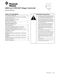
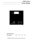
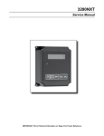
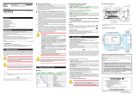
FLECK® 3200 NXT
SERVICE MANUAL
©2013 Pentair Residential Filtration, LLC
www.pentairaqua.com
TABLE OF CONTENTS
JOB SPECIFICATION SHEET
JOB SPECIFICATION SHEET.................................................2
INSTALLATION......................................................................3
TIMER OPERATION...............................................................3
SYSTEM DEFINITIONS..........................................................5
SYSTEM OPERATION IN SERVICE
(SYSTEM 14-DEMAND RECALL)...........................................6
FLOW IN A FOUR-UNIT SYTEM
(SYSTEM 14-DEMAND RECALL)...........................................7
TIMER DISPLAY FEATURES..................................................7
TIMER DISPLAY - SCREEN EXAMPLES
(SYSTEM 4 THROUGH 6).......................................................7
TRANSFORMER AND GROUND CONNECTIONS..................8
NETWORK/COMMUNICATION CABLES
AND CONNECTIONS.............................................................8
MASTER PROGRAMMING MODE FLOW CHART...................9
USER PROGRAMMING MODE FLOW CHART...................... 11
DIAGNOSTIC PROGRAMMING MODE FLOW CHART.......... 12
2750/2850/2900S UPPER & 2900S LOWER
POWERHEAD ASSEMBLY................................................... 14
3150/3900 UPPER & LOWER POWERHEAD ASSEMBLY.... 16
METER ASSEMBLY PLASTIC.............................................. 18
1-INCH METER ASSEMBLY BRASS.................................... 20
1-1/2 INCH METER ASSEMBLY BRASS.............................. 21
2-INCH METER ASSEMBLY BRASS.................................... 22
3-INCH METER ASSEMBLY BRASS.................................... 23
SINGLE PISTON WIRING DIAGRAM.................................... 24
DUAL PISTON WIRING DIAGRAM....................................... 25
REMOTE TIMER WIRING DIAGRAM.................................... 26
2750/2850 REMOTE TIMER WIRING DIAGRAM.................. 27
2900 REMOTE TIMER WIRING DIAGRAM........................... 28
3900 REMOTE TIMER WIRING DIAGRAM........................... 29
3150 REMOTE METER WIRING DIAGRAM.......................... 30
TROUBLESHOOTING........................................................... 31
CALIFORNIA PROPOSITION 65 WARNING......................... 31
Please Circle and/or Fill in the Appropriate Data for
Future Reference:
2 • FLECK 3200 NXT Service Manual
®
Programming Mode:
Feed Water Hardness:________ Grains per Gallon or Liters
Regeneration Time: Delayed_______ AM/PM or Immediate
Regeneration Day Override: Off or Every___________ Days
Time of Day:______________________________________
Master Programming:
System Type:
4 - Single Unit
5 - Parallel Unit
6 - Parallel Series Regen
7 - Twin Alternating
9 - Alternating
14 - Demand Recall
Valve Type: 2750
2850
2900s 3150
3900
System Size: 2 Valves
3 Valves
4 Valves
Valve Address: #1
#2
#3
#4
Regenerant Flow: Downflow or Upflow
Brine Draw First or Brine Fill First
Display Format: US Gallons or Liters
Unit Capacity:_ ________________ Grains or grams CaCO3
Capacity Safety Factor: Zero or ____________________ %
Feed Water Hardness:______Grains or milligrams CaCO3/L
Trip Points (Gallons or M3):_____ Point 1 _____ Point 2 _____
Point 3
Trip Delays: Delay 1 ______ Delay 2 ______ Delay 3 ______
Regeneration Cycle Step #1:
__:__:__
Regeneration Cycle Step #2:
__:__:__
Regeneration Cycle Step #3:
__:__:__
Regeneration Cycle Step #4:
__:__:__
Regeneration Cycle Step #5:
__:__:__
Timed Auxiliary Relay Output Window:
Off or Start Time _ _ : _ _ : _ _
End Time _ _ : _ _ : _ _
Chemical Pump Output Auxiliary Relay:
Off or Volume (Gallons or Liters)
Time _ _ : _ _ : _ _
Fleck Flow Meter Size:
Paddle: 1-inch 1.5-inch 2-inch 3-inch
Turbine:1-inch 1.5-inch
Generic Flow Meter:
Maximum Flow Rate: Add _ _ Gallons every _ _Pulses
IMPORTANT PLEASE READ:
• The information, specifications and
illustrations in this manual are based
on the latest information available at
the time of printing. The manufacturer
reserves the right to make changes at
any time without notice.
• This manual is intended as a guide for
service of the controller only. System
installation requires information from
a number of suppliers not known at the
time of manufacture. This product should
be installed by a plumbing professional.
• This unit is designed to be installed on
potable water systems only.
• This product must be installed in
compliance with all state and municipal
plumbing and electrical codes. Permits
may be required at the time
of installation.
• If daytime operating pressure exceeds
80 psi, nighttime pressures may exceed
pressure limits. A pressure reducing
valve must be installed.
• Do not install the unit where
temperatures may drop below 32°F (0°C)
or above 110°F (43°C).
• Do not place the unit in direct sunlight.
Black units will absorb radiant heat
increasing internal temperatures.
• Do not strike the controller or any of
the components.
• Warranty of this product extends to
manufacturing defects. Misapplication
of this product may result in failure to
properly condition water, or damage
to product.
• A prefilter should be used on
installations in which free solids
are present.
• Correct and constant voltage must be
supplied to the controller to maintain
proper function.
INSTALLATION
Water Pressure
A minimum of 20 pounds (1.4 bar) of water pressure is
required for regeneration valve to operate effectively.
Electrical Facilities
An uninterrupted alternating current (A/C) supply is required.
NOTE: Other voltages are available. Please make sure your
voltage supply is compatible with your unit
before installation.
TIMER OPERATION
Setting the Time of Day
NOTE: Set Time of Day on the Lead Unit (#1) and the rest of
the units in the system will update the Time of Day
within 10 seconds.
1. Press and hold the Up or Down button for 2 seconds.
2. Press the Shift button to select the digit you want
to modify.
3. Press the Up or Down buttons to adjust the valve.
4. Press the Extra Cycle button to return to the normal
display screen, or wait for a 5 second timeout.
NOTE: The “D” button (Diagnostic) can be pressed to exit
without saving.
Manually Initiating a Regeneration
1. When timer is In Service or Stand By, press the Extra Cycle
button for 5 seconds on the main screen.
2. The timer advances to Regeneration Cycle Step #1, and
begins programmed time count down.
3. Press the Extra Cycle button once to advance valve to
Regeneration Cycle Step #2 (if active).
4. Press the Extra Cycle button once to advance valve to
Regeneration Cycle Step #3 (if active).
5. Press the Extra Cycle button once to advance valve to
Regeneration Cycle Step #4 (if active).
6. Press the Extra Cycle button once to advance valve to
Regeneration Cycle Step #5 (if active).
7. Press the Extra Cycle button once more to advance the
valve back to In Service.
NOTE: A manually initiated or queued regeneration can
be cleared by pressing the Extra Cycle button for
less than 5 seconds. A system queued regeneration
can only be cleared by stepping through a manual
regeneration. If regeneration occurs for any reason
prior to the delayed regeneration time, the manual
regeneration request shall be cleared. Pressing the
Extra Cycle button while in regeneration will cause
the upper drive to advance to the next
step immediately.
FLECK 3200 NXT Service Manual • 3
®
TIMER OPERATION CONTINUED
Timer Operation During Regeneration
In the Regeneration Cycle step display, the timer shows
the current regeneration cycle number the valve is in, or
has reached, and the time remaining in that step. Once all
regeneration steps are complete the timer returns to In
Service and resumes normal operation.
Example: 12 minutes remaining in Cycle 1 (Backwash)
Press the Extra Cycle button during a system queued
Regeneration Cycle to immediately advance the valve
to the next cycle step position and resume normal
step timing.
Flow Meter Equipped Timer
As treated water is used, the Volume Remaining display counts
down from the calculated system capacity to zero. When zero
is reached a Regeneration Cycle begins if no other units are
in regeneration.
Timer Operation During Programming
The timer enters the Program Mode in Standby or Service
Mode as long as it is not in regeneration. While in the Program
Mode the timer continues to operate normally monitoring
water usage. Timer programming is stored in memory
permanently.
Timer Operation During A Power Failure
All program settings are stored in permanent memory.
Current valve position, cycle step time elapsed, and time of
day are all stored during a power failure, and will be restored
when power is re-applied. Time is kept during a power failure,
and time of day is adjusted upon power up (as long as power is
restored within 12 hours).
NOTE: The time of day on the main display screen will flash
for 5 minutes when there has been a power outage.
The flashing of the time of day can be stopped by
pressing any button on the display.
Remote Lockout
The timer does not allow the unit/system to go into
Regeneration until the Regeneration Lockout Input signal to
the unit is cleared. This requires a contact closure to activate
the unit. The recommended gauge wire is 20 with a maximum
length of 500 feet. See P4 remote inputs in the wiring
diagrams in the service manual.
Regeneration Day Override Feature
If the Day Override option is turned on and the valve reaches
the set Regeneration Day Override value, the Regeneration
Cycle starts if no other unit is in Regeneration. If other units
are in regeneration, it is added to a regeneration queue. This
occurs regardless of the remaining volume available.
WARNING: Transformer must be grounded and ground
wire must be terminated to the back plate
where grounding label is located
before installation.
4 • FLECK 3200 NXT Service Manual
®
SYSTEM DEFINITIONS
System
Number
System
Description
# of
Tanks/
Controls
Type
Operation Discussion
4
Single Unit
1
Time Clock: No Meter
Immediate: One Meter
Delayed: One Meter
Remote Signal Start: No
Meter
Single tank configuration.
5
Interlocked
2, 3, or 4
Immediate: All Meters
Remote Signal Start: No
Meter
All tanks in parallel supplying treated water. Each
unit in the system will have its own flow meter/sensor
input. The control will delay the start of Regeneration if
another unit is already in Regeneration. Once that unit
has completed a Regeneration cycle, and has returned
to Service,the unit with longest regeneration queue time
will begin Regeneration. No more than one unit will be in
Regeneration at a time.
6
Series
2, 3, or 4
Regeneration
Immediate: One Meter
Delayed: One Meter
Remote Signal Start: No
Meter
All tanks in parallel supplying treated water. Only #1
control will monitor flow meter/sensor input. When a
regeneration is required for the system, it will regenerate
valve address #1 first, immediately followed by #2, then
#3, then #4 if installed. No more than one unit will be in
Regeneration at a time.
7
Twin
Alternating
Immediate: One Meter
Remote Signal Start: No
Meter
One tank online supplying treated water, one tank in
Standby. Only #1 control will monitor its flow meter/sensor
input. Regeneration of a unit will begin after the other
control has left Standby and returned to Service. When the
Regeneration cycle is complete, the regenerated unit will
enter Standby. Standby on each tank is controlled by the
lower drive output terminals on the NXT circuit board.
9
Multiple Tank 2, 3, or 4
Alternating
Immediate: All Meters
Remote Signal Start: No
Meter
One, two, or three tanks online supplying treated water,
one tank in Standby. Meter/sensor input is required on
each tank. Regeneration of a unit will begin after the other
control has left Standby and returned to Service. When the
Regeneration cycle is complete, the regenerated unit will
enter Standby. Standby on each tank is controlled by the
lower drive output terminals on the NXT circuit board.
14
Demand
Recall
Immediate: All Meters
Meter input is required on each tank. Unit #1 will begin
In Service with #2, #3, and #4 (if installed) will begin in
Standby. At least one unit is In Service at all times. When
flow rate to the Primary Service Unit increases to a user
specified rate, the next unit in sequence will move from
Standby to Service. As the flow rate falls below the user
specified rate subsequent tanks will return to Standby.
When the Primary Service Unit regenerates, the next unit
in sequence will become the new Primary Service Unit. As
each units capacity is reached the controller will initiate
a Regeneration of that unit. Depending on the number of
units in the system, and flow rate demand the regenerated
unit will then be placed either into Standby or Service. Only
one unit will be in Regeneration at a time.
2
2, 3, or 4
FLECK 3200 NXT Service Manual • 5
®
SYSTEM OPERATION IN SERVICE
(SYSTEM 14-DEMAND RECALL)
5. The third valves returns to stand by as demand decreases
past the second trip point.
The system operates as part of a multi-valve
regeneration system.
Each valve in the system will have an active flow meter input,
even in Standby.
The number of valves in service depends on the flow rate.
Examples of a Four-Unit System:
1. One Valve is in service at all times (the “primary valve”).
1
2
In Service
(Primary Tank)
3
2
3
4
Standby
2
Full Capacity
4th in Standby
(Primary Valve)
3
3/4 Capacity
1/2 Capacity
3rd in Standby 2nd in Standby
4
1/4 Capacity
1st in Standby
7. The primary valve regenerates. The next valve with the
least remaining volume becomes the new primary valve.
The valve with the next least volume remaining will be the
first trip point programmed rate. Valves continue operating
in this order.
System Operation in Regeneration:
In Service
Standby
3. The flow rate demand decreased below the first trip point.
The valve returns to Standby.
1
2
Flow Rate Demand
Below First Trip Point
(Primary Valve)
3
4
Standby
4. Total flow rate demand increased past a second trip point
programmed rate. The second and third valve (least volume
remaining) changes from Standby to In Service. The total
flow is split between the three meters.
2
3
4
Standby
Flow Split Between
Three Meters
6 • FLECK 3200 NXT Service Manual
®
4
6. Valves return to stand by due to decreased total flow rate
and trip points programmed. The valve with the most
remaining volume will be the first to go into Standby.
1
Total Flow Split
Between Two Meters
1
3
Flow Split Between
Two Meters
Standby
1
2
4
2. The total flow rate to the primary valve increased past
the first trip point programmed rate. The flow stayed past
the trip point delayed time. The next valve (least volume
remaining) changes from Standby to In Service. This valve
then splits the total flow between two meters.
First Trip Point
(Primary Valve)
1
1
2
3
4
Full Capacity
4th in Standby
3/4 Capacity
3rd in Standby
1/2 Capacity
First Trip Point
Programmed Rate
1/4 Capacity
New Primary Tank
If two valves are In Service and both reach
Volume Remaining = 0, the other two valves will shift from
Standby to In Service. The lead valve with Volume Remaining
= 0 will start regeneration. The second valve with Volume
Remaining = 0 will enter Standby. If flow increases past the
trip point a third valve needs to enter In Service. The valve in
Standby with Volume Remaining = 0 will shift into In Service to
maintain a steady flow. Operating for extended periods in this
mode may degrade the water quality.
FLOW IN A FOUR-UNIT SYTEM (SYSTEM
14-DEMAND RECALL)
Steady Flow:
1
2
3
4
In Service
In Service
Standby
Standby
Volume
Remaining = 0
Volume
Remaining = 0
INI (Initializing) - INI will display on the screen for 30 to 45
seconds when initializing after a power failure reset
or programming.
RGQ (Regeneration Queued) -RGQ indicates that the reserve
has been entered in a delayed system and regeneration has
been queued. When in the main screen, press the Extra Cycle
button to toggle service (SRV) with RGQ.
Service (SRV) - SRV will display when the unit is in service.
LCK (Lock) - Lock will be displayed when the terminal/remote
input block P4 on the circuit board is switched to “lock”. See
the “Network/Communication Cables & Connections” section
of this manual.
LED Status Lights
Blue LED - Illuminates while the unit is in service and no
errors exist. A blinking blue light indicates the timer is in
service, and queued for regeneration.
Green LED - Illuminates when the unit is in Regeneration
mode, unless an error condition exists. A blinking green light
indicates the timer is in Standby, and not in Regeneration.
Red LED- Illuminates when there is an error.
Flow Stays Steady:
1
2
3
4
Regeneration
Standby
In Service
In Service
Flow Indicator
A rotating line (appearing as a rotating star shape) will display
on the screen when flow is going through the meter.
TIMER DISPLAY - SCREEN EXAMPLES
(SYSTEM 4 THROUGH 6)
Flow Increases Past the Trip Point:
1. In Service: System 4 Time Clock
1
2
Regeneration
In Service
(Volume
(Volume
Remaining = 0) Remaining = 0)
3
4
In Service
In Service
Valve
Address
Flow
System
Indicator
Number
Time
of Day
Display Screen
Time of Day alternates
with Error Screen
Example: Valve #, Volume
Remaining, Errors
Volume Remaining
Diagnostic Button
View Flow Rate, Peak Flow
Rate, Totalizer, Hours
Between Last Two
Regenerations, Hours Since
Last Regeneration, Adjustable
Volume Remaining, Valve
Position, Send & Receive
Errors, Software Version
Extra Cycle Button
Cycle Valve in
Regeneration/Cycle
Programming Steps
Shift Button
Adjusts Values to the Left
Up Button
Adjusts Values Up
03:45PM
REGEN IN 07 DAYS
4#
SRV* 03:45PM
VOLUME
1000 g
3. In Service: System 5 Flow Meter Initiated (Lead Unit)
5#1 SRV* 03:45PM
VOLUME
1000 g
4. In Service: System 5 Flow Meter Initiated (Lag Unit #3)
5#3 SRV
03:45PM
VOLUME
1000 g
Down Button
Adjusts Values Down
Status LED
Figure 1
Valve State
SRV
2. In Service: System 4 Flow Meter Initiated or System 4 Flow
Meter Delayed
TIMER DISPLAY FEATURES
Valve State
(SBY, SRV, INI, CHG, LCK)
4#
CHG (Change of State) - CHG will be displayed when the lower
drive changes from one state to another in dual piston valves.
5. In Service: System 6 Flow Meter Initiated (Lead Unit)
6#1 SRV* 03:45PM
SYSVOL
4000 g
FLECK 3200 NXT Service Manual • 7
®
TRANSFORMER AND GROUND
CONNECTIONS
NETWORK/COMMUNICATION CABLES
AND CONNECTIONS
2750/2850/2900 Valves:
Use either a CAT3 or CAT5 Network/Communication cable.
Connect the network/communication cable first
before programming.
The maximum cable length between timers is 100 feet.
Connect each unit together from one communication port to
the next communication port. It does not matter which one
goes to the next one.
Lock
Ground
Communication Ports
Regen
3150/3900 Valves:
Figure 2 Current NXT Circuit Board
IMPORTANT: Earth ground wire must be installed.
Installing the Transformer:
1. Locate the ground label to find the screw to attach the
ground wire on the transformer.
2. Remove the screw and attach the ground wire, and
re-attach the screw.
8 • FLECK 3200 NXT Service Manual
®
System 14 (2-4 units) Demand Recall
Example:
Valve Address #2 (Second Control Valve) (Default)
VALVE ADDRESS:
MASTER PROGRAMMING MODE FLOW
CHART
CAUTION Before entering Master Programming, please
contact your local professional water dealer.
NOTE: Depending on current option settings, some displays
cannot be viewed or set.
Entering Master Programming Mode
1. Press and hold the Shift and Up buttons for 5 seconds.
Press the Extra Cycle button once per display until all
displays are viewed and Normal Display is resumed. Option
setting displays may be changed as required by pressing
either Up or Down button. Use the Shift button to move one
space to the left.
2. Depending on current valve programming, certain displays
may not be viewed or set.
NOTE: If the “D” button is pressed while in master
programming, no changes will be saved.
Exiting Master Programming Mode
1. Press the Extra Cycle button once per display until all
are viewed. Master Programming Mode is exited and the
normal display screen appears.
2. To exit the Master Programming Mode without saving
changes, press the Diagnostic button.
NOTE: If no keypad activity is made for 5 minutes while in
the Master Programming Mode, or if there is a power
failure, no changes will be saved, and the unit will go
back to the main display screen.
Resets
Soft Reset: Press and hold the Up and Down buttons for 25
seconds until 12:00PM (or 12:00HR) appears. This resets all
parameters except for the flow meter totalizer volume.
Master Reset: Hold the Extra Cycle button while powering up
the unit. This resets all of the parameters in the unit. Check
and verify the choices selected in Master Programming Mode.
NOTE: If the “D” button is pressed while in master
programming, no changes will be saved.
#2
Options: Valve Address #1 (First Control Valve)
Valve Address #2 (Second Control Valve) (Default)
Valve Address #3 (Third Control Valve)
Valve Address #4 (Fourth Control Valve)
NOTE: This screen will not display for System Type 4.
Options: 2 Valves in the System (Default)
3 Valves in the System
4 Valves in the System
Range: 2 to 4 Valves in the System
NOTE: This screen will not display for System Type 4.
Example:
English
Options: English
Espanol
Portugues
Deutsch
Francais
Options: Time Clock Delayed (System 4 Only) (Default)
Meter Immediate (All System Types)
Meter Delayed Fixed Reserve (Systems 4 & 6 Only)
2750
Options: 2750 (Default)
2850
2900
3150
3900
Stager - Notch Cam
REGENERANT FLOW:
DOWNFLOW
4
Example:
System Type 4, Single Unit
Options: System 4 (single unit)
System 5 (2-4 units) Parallel Interlock
System 6 (2-4 units) Parallel Series Regeneration
System 7 (2 units) Alternating
System 9 (2-4 units) Alternating
System 14 (2-4 units) Demand Recall
VALVE ADDRESS:
#2
Example:
Valve Address #2 (Second Control Valve) (Default)
Options: Valve Address #1 (First Control Valve)
Valve Address #2 (Second Control Valve) (Default)
Valve Address #3 (Third Control Valve)
Valve Address #4 (Fourth Control Valve)
Example:
Downflow (Default)
Options: Downflow (Default)
Up Flow
UF Fill First
REMOTE SIGNAL
START:
00:06:00
Example:
00:06:00 (Default)
(Hours:Minutes:Seconds)
Options: 00:06:00 (Default)
Range: 1 second to 99 minutes (1 hour, 39 minutes)
NOTE: This display will not be viewed in System 4
DISPLAY FORMAT:
US-GALLONS
Example:
U.S. Gallons (Default)
Options: U.S. - Gallons (Default)
Eu Metric - Liters (Metric)
NOTE: In U.S. - Gallons mode, the display will be in 12-hour time.
NOTE: In European Units - Liters (Metric) mode, the display will be in
24-hour time.
Example:
Grains (Default)
Options: Grains (in U.S. Format) (Default)
Grams (in Metric Format)
Range: 1 to 9,900,000 Grain Capacity in U.S. Format
1 to 198,000 grams CaCO3 Capacity in Metric Format
NOTE: Use the Shift button to move to the left.
FACTOR:
SINGLE UNIT
Example:
2750 (Default)
VALVE TYPE:
CAPACITY SAFETY
SYSTEM TYPE:
Example:
Time Clock Delayed (Default)
REGEN TYPE:
TIME CLK DELAYED
UNIT CAPACITY:
00000000 GRAINS
SELECT LANGUAGE:
ENGLISH
Example:
2 Valves in the System (Default)
SYSTEM SIZE:
2 VALVES
00%
Example:
00% (Default)
Range: 0 to 50%
NOTE: Use the Shift button to move to the left.
FEED WATER
HARDNESS: 15 GPG
Example:
15 GPG (U.S. Format) (Default)
Range: 1 to 199 Grains/Gallon (U.S. Format)
20 to 1,999 miligrams CaCO3/L (Metric Format)
NOTE: Use the Shift button to move to the left.
NOTE: This screen will only display on the lead unit for System Types 6 & 7.
For all other System Types, it will display for all units.
TRIP POINT 1:
000 gpm
NOTE: This screen will not display for System Type 4.
SYSTEM SIZE:
2 VALVES
Example:
2 Valves in the System (Default)
Options: 2 Valves in the System (Default)
3 Valves in the System
4 Valves in the System
Range: 2 to 4 Valves in the System
NOTE: This screen will not display for System Type 4.
NOTE: Display will not appear unless timer is programmed as valve position
#1. Use the Shift button to change each
decimal position.
®
FLECK 3200 NXT Service Manual • 9
TRIP DELAY 1:
30 SECONDS
Options: Time Clock Delayed (System 4 Only) (Default)
Meter Immediate (All System Types)
Meter Delayed Fixed Reserve (Systems 4 & 6 Only)
Example:
MASTER PROGRAMMING
MODE FLOW
2750 (Default)
2750 (Default)
CHARTOptions:
CONTINUED
2850
VALVE TYPE:
NOTE: Display will not appear unless timer is programmed as valve position
#1. System size must be 3 or 4 to appear. Use the Shift button to move one
space to the left.
2750
2900
3150
3900
Stager
- Notch Cam
step
selects
up
TRIP DELAY 2:
30 SECONDS
Trip Points 1, 2, and 3 (System 14 only)
This program
to three Trip Points programmed
on the master timer only (Valve Address #1).
FLOW:
The actualREGENERANT
required
number
ofExample:
Trip Points in a system is one
DOWNFLOW
Downflow (Default)
less than the number of valves in the system.
Options: Downflow (Default)
Trip Point 1 represents
Up Flow the system flow rate at which a second
UF Fill First
valve will be brought
In Service or Standby.
Trip Point 2 represents the system flow rate at which a third
REMOTE SIGNAL
Example:
valve will be
brought
In Service00:06:00
or Standby.
START:
00:06:00
(Default)
(Hours:Minutes:Seconds)
Trip Point Options:
3 represents
the system flow rate at which a fourth
00:06:00 (Default)
Range:
1 second In
to 99
minutes (1or
hour,
39 minutes)
valve will be
brought
Service
Standby.
NOTE: Display will not appear unless timer is programmed as valve position
#1. System size must be 3 or 4 to appear. Use the Shift button to move one
space to the left.
TRIP POINT 3:
gpm
NOTE: Display will not appear unless timer is programmed as valve position
#1. System size must be 4 to appear. Use the Shift button to move one
space to the left.
NOTE: This display will not be viewed in System 4
Trip Point 1
Trip Point 2
Range:
U.S.:
1 – 997Options:
GPM U.S. - Point
1 plus 1 to 998
Gallons (Default)
Trip Point 3
Example:
Value
Trip(Default)U.S.:
U.S.of
Gallons
DISPLAY FORMAT:
US-GALLONS
Trip Point 2
plus 1 to 999
- Liters (Metric)
Range: Eu Metric
Metric:
Value of Trip
NOTE: In U.S. - Gallons mode, the display will beMetric:
in 12-hour Trip
time. Point
0.01 –NOTE:
9.97In European
Point
1
plus .01 to
Units - Liters (Metric) mode, 2
theplus
display
will be
0.01
toin9.99
3
M /M
9.98
24-hour time.
Trip Delays 1, 2, and 3 (System 14 only)
UNIT CAPACITY:
00000000 GRAINS
Example:
Grains (Default)
This program
step
selects
each (Default)
Trip Delay time that is
Options:
Grains
(in U.S. Format)
Grams (in
Metric
Format)
addressed with each
Trip
Point
and will be programmed on
Range: 1 to 9,900,000 Grain Capacity in U.S. Format
the Master
timer1 toonly
(Valve Address #1). The Trip Delay time
198,000 grams CaCO3 Capacity in Metric Format
represents
a minimum
of time
the system flow rate
NOTE:
Use the Shiftamount
button to move
to the left.
is required to be equal or greater than the Trip Points to bring
a unit In Service.
It also is the Example:
minimum amount of time the
CAPACITY SAFETY
FACTOR:
00%
system flow
rate is required
to00%
be(Default)
less than the Trip Points to
remove a Range:
unit from
In Service to Standby.
0 to 50%
NOTE: Use the Shift button to move to the left.
Trip Delay 1
Default:
30WATER
FEED
HARDNESS: 15
Seconds
30 -
Trip Delay 2
GPG
Trip Delay 3
Example:
15 GPG (U.S. Format) (Default)
Range: 1 to 199 Grains/Gallon (U.S. Format)
Range:
Range:
20 to 1,999 miligrams
CaCO3/L (Metric Format) Range:
99 NOTE:
Seconds
30 - 99 Seconds
30 - 99 Seconds
Use the Shift button to move to the left.
NOTE: This screen will only display on the lead unit for System Types 6 & 7.
For all other System Types, it will display for all units.
TRIP POINT 1:
000 gpm
TRIP DELAY 3:
30 SECONDS
NOTE: Display will not appear unless timer is programmed as valve position
#1. System size must be 4 to appear. Use the Shift button to move one
space to the left.
REGENERATION DAY
OVERRIDE:OFF
REGENERATION DAY
OVERRIDE:01 DAYS
Options: Off (Default for meter) or On
Range: 1 to 99 Days
REGENERATION
TIME:
02:00AM
Regeneration Cycle Steps
This step programs
the Regeneration
CYCLE 1 00:00:00
Example: Cycle step times 1
WASH
1 in Back Wash Mode
through 5. PleaseBACK
Refer
to theCycle
chart
below for regenerant flow
default cycle
steps
and times.
Options:
Regeneration
Cycle Step #1
Regeneration Cycle Step #2
Regeneration Cycle Step #3
Regeneration
#4
Cycle 1Cycle StepTime
Cycle 2
Time
Regeneration Cycle Step #5
NOTE: Please refer to the “Regenerant Flow Default Cycle Steps & Times”
in the Master
Programming Mode 10
section of theBrine
manual.&
Downflow
Backwash
1 Hour
Minutes
RinseCycle Step
NOTE: If Stager is chosen for Valve
Type, the Slow
Regeneration
description will not display.
Regenerant
Flow
Brine &
Slow Rinse
Brine Tank
DISABLED
UF Fill First
Fill
AUXILIARY RELAY:
TRIP DELAY 1:
30 SECONDS
Options: Enabled
Disabled (Default)
Regenerant
Flow
Downflow
Backwash
Example:
12 Relay is Disabled
Brine
Auxiliary
Minutes
Making
Time
Cycle 4
Example:
10 Relay Output
Brine
Tank1 at
Auxiliary
in Start
0Minutes
hours, 0 minutes, & 0Fill
seconds
10
Minutes
1 Hour
Time
12
Minutes
00:00:00 to 18:00:00
Types 6 & 7.
Brine &
Slow Rinse
AUX RELAY OUTPUT
1 00:00:00
END
Regenerant
Flow
Range:
NOTE: Display will not appear unless timer is programmed as valve position
#1. System size must be 3 or 4 to appear. Use the Shift button to move one
space to the left.
Rapid Rinse
1 Hour
10
Brine Tank
12
NOTE: Only
displayed
if Auxiliary Relay is enabled in previous screen.
UF Brine Draw
Rapid
Rinse
Minutes
Minutes
Auxiliary Relay will only display
if Chemical Pump Fill
is OFF for System
UF Fill First
TRIP POINT 2:
gpm
Cycle 3
AUX RELAY OUTPUT
START 1 00:00:00
Range:
NOTE: Display will not appear unless timer is programmed as valve position
#1. Use the Shift button to move one space to the left.
Example:
2:00 A.M. (Default)
Options: A.M. (U.S. Format)
HR (Metric Format)
NOTE: Regeneration time will not appear unless Regeneration Day Override
is on.
UF Brine Draw
NOTE: Display will not appear unless timer is programmed as valve position
#1. Use the Shift button to change each decimal position.
Example:
Off (Default)
On (Default for time clock)
Example:
1 Day
Downflow
Cycle 5
Backwash
10
Minutes
Example:
Auxiliary Relay Output in End 1 at
0 hours,
Time0 minutes, & 0 seconds
00:00:00 to 18:00:00
Pause
CHEMICAL PUMP:
DISABLED
UF Brine Draw
1 Hour
Pause
N/A
Example:
Chemical Pump is Disabled
N/A
Options: Enabled
Disabled (Default)
TRIP DELAY 2:
30 SECONDS
10 • FLECK 3200 NXT Service Manual
10
UF Fill First
Rapid
NOTE: This
screenRinse
will only display on the lead unit for System Types 6 & 7.
Minutes
For all other System Types, it will display for all units.
®
NOTE: Display will not appear unless timer is programmed as valve position
#1. System size must be 3 or 4 to appear. Use the Shift button to move one
CPO AUX RELAY
VOLUME:
000 g
Example:
Energize Chemical Pump Relay Every 50 Gallons
Energize Chemical Pump Relay Every 200 L
Range: 1 to 99 Days
REGENERATION
TIME:
02:00AM
Example:
2:00 A.M. (Default)
MASTER
PROGRAMMING MODE FLOW
Options: A.M. (U.S. Format)
HR (Metric Format)
CHARTNOTE:
CONTINUED
Regeneration time will not appear unless Regeneration Day Override
2.0 Paddle (Fleck)
3.0 Paddle (Fleck)
Generic (Non-Fleck)
NOTES: Default flow meter type is based on the valve type. This screen will
only display on the lead unit for System Types 6 & 7. All other system types
it will display for all units.
MAXIMUM FLOW
RATE:
0000 gpm
is on.
Range:
CYCLE 1 00:00:00
BACK WASH
Example:
Cycle 1 in Back Wash Mode
Options: Regeneration Cycle Step #1
Regeneration Cycle Step #2
Regeneration Cycle Step #3
Regeneration Cycle Step #4
Regeneration Cycle Step #5
NOTE: Please refer to the “Regenerant Flow Default Cycle Steps & Times”
in the Master Programming Mode section of the manual.
NOTE: If Stager is chosen for Valve Type, the Regeneration Cycle Step
description will not display.
AUXILIARY RELAY:
DISABLED
Example:
Auxiliary Relay is Disabled
Example:
Maximum Flow Rate of 0 gpm
20 - 2,000 gpm (U.S. Format)
20 - 200.0 L (Metric Format)
NOTE: Only displayed if “Generic” is chosen for the flow meter.
ADD 01 GALLONS
EVERY 001 PULSES
Example:
Add 1 Gallon for Each Pulse in U.S. Format
Options: Gallons (U.S. Format)
Liters (Metric Format)
Range:
1 - 255Gallons (U.S. Format)
0.1 - 09.9 L (Metric Format)
Pulses: 1 - 255
NOTE: Only displayed if “Generic” is chosen for the flow meter.
PROGRAMMING UNIT
PLEASE WAIT...
Example:
Master Programming Mode is Exiting
Options: Enabled
Disabled (Default)
AUX RELAY OUTPUT
START 1 00:00:00
Range:
Example:
Auxiliary Relay Output in Start 1 at
0 hours, 0 minutes, & 0 seconds
00:00:00 to 18:00:00
NOTE: Only displayed if Auxiliary Relay is enabled in previous screen.
Auxiliary Relay will only display if Chemical Pump is OFF for System
Types 6 & 7.
AUX RELAY OUTPUT
END 1 00:00:00
Range:
Example:
Auxiliary Relay Output in End 1 at
0 hours, 0 minutes, & 0 seconds
00:00:00 to 18:00:00
CHEMICAL PUMP:
DISABLED
Example:
Chemical Pump is Disabled
Options: Enabled
Disabled (Default)
USER PROGRAMMING MODE FLOW
CHART
Entering User Programming Mode
Hold the Set Up and Set Down buttons for 5 seconds.
NOTE: User Mode is only displayed when a metered option
is chosen under System Type. Depending on current
option settings, some displays cannot be viewed
or set.
NOTE: User Mode cannot be entered on the Lag unit for
System 6.
NOTE: This screen will only display on the lead unit for System Types 6 & 7.
For all other System Types, it will display for all units.
CPO AUX RELAY
VOLUME:
000 g
Example:
Energize Chemical Pump Relay Every 50 Gallons
Energize Chemical Pump Relay Every 200 L
Range:
1 to 999 gallons in U.S. Format
1 to 9.999 L in Metric Format
NOTE: Only displayed on units that physically have a meter (Lead always has
a meter). Only shown if Auxiliary Relay is disabled on System Types 6 & 7.
CPO AUX RELAY
TIME:
Range:
00:00:00
Example:
Each Time the Chemical Pump Relay is on, Run
for 30 Seconds (00:00:30)
gpg
REGENERATION DAY
OVERRIDE: OFF
00:00:00 to 02:00:00
FLOW METER:
1.0 PADDLE
Example:
1.0 Paddle Flow Meter
Options: 1.0 Paddle (Fleck)
1.0 Turbine (Fleck)
1.5 Paddle (Fleck)
1.5 Turbine (Fleck)
2.0 Paddle (Fleck)
3.0 Paddle (Fleck)
Generic (Non-Fleck)
NOTES: Default flow meter type is based on the valve type. This screen will
only display on the lead unit for System Types 6 & 7. All other system types
it will display for all units.
MAXIMUM FLOW
RATE:
0000 gpm
Range:
FEED WATER
HARDNESS:
REGENERATION DAY
OVERRIDE:99 DAYS
REGENERATION
TIME:
02:00AM
Example:
Maximum Flow Rate of 0 gpm
20 - 2,000 gpm (U.S. Format)
20 - 200.0 L (Metric Format)
NOTE: Only displayed if “Generic” is chosen for the flow meter.
ADD 01 GALLONS
EVERY 001 PULSES
Example:
Add 1 Gallon for Each Pulse in U.S. Format
Options: Gallons (U.S. Format)
Liters (Metric Format)
Range:
1 - 255Gallons (U.S. Format)
0.1 - 09.9 L (Metric Format)
Pulses: 1 - 255
NOTE: Only displayed if “Generic” is chosen for the flow meter.
FLECK 3200 NXT Service Manual • 11
®
DIAGNOSTIC PROGRAMMING MODE FLOW
CHART
Entering Diagnostic Programming Mode
1. Push and release the "D" button.
2. Press the Extra Cycle button once per display until all
displays are viewed and Normal Display is resumed.
3. Push and release the"D" button at anytime during
diagnostic mode and the timer will exit the mode.
4. Depending on the current controller programming, certain
displays may not be able to be viewed or set.
Overview Diagnostic Mode
The current diagnostic will be displayed until Extra Cycle key is
pressed. There is no time limit on each display. The timer will
display local information, not system information. In the event
of a regeneration occurring while displaying diagnostics, the
regeneration step and time remaining will be displayed. When
regeneration has been completed, the display will return to
the main screen.
CURRENT FLOW
RATE:
0 gpm
Example:
Flow rate at this time.
PEAK FLOW RATE:
0 gpm
Example:
Peak flow since last regeneration.
TOTALIZER:
130 g
LAST TWO REGENS:
0 HOURS
Example:
Gallons at the outlet since installation.
Example:
Hours between the last regeneration and the
one before it.
LAST REGEN
0 HOURS
Example:
Hours since last regeneration.
VOLUME REMAIN:
1000 g
Example:
Volume remaining (can be adjusted).
NOTE: If a System 6, Unit #1 of “Tank Remaining” will display “System
Remaining”.
VALVE ADDRESS
#2
Example:
Controller unit number.
VERSION:
Example:
Installed software level of the controller in use.
X.XX
12 • FLECK 3200 NXT Service Manual
®
FLECK 3200 NXT Service Manual • 13
®
Valve Address
Select Language
System Size
Regen Type
Valve Type
Regenerant Flow
Remote Signal Start
Display Format
Unit Capacity
Capacity Safety Factor
Feed Water Hardness
Trip Point 1
Trip Delay 1
Trip Point 2
Trip Delay 2
Trip Point 3
Trip Delay 3
Regeneration Day Override
Regeneration Time
Cycle 1
Cycle 2
Cycle 3
Cycle 4
Cycle 5
Auxiliary Relay
Aux Relay Output Start
Aux Relay Output End
Chemical Pump
CPO Aux Relay Volume
CPO Aux Relay Time
Flow Meter
Generic
Maximum Flow Rate
Add _ _ _ Gallons or Liters
Every _ _ _ Pulses
Notes
System Type
x
x
x
x
x
x
x
x
x
o
x
x
x
x
x
x
c
c
x
c
c
x
x
a
a
a
x
x
x
x
x
x
x
x
x
x
x
x
x
c
c
x
o
x
x
x
x
x
x
c
c
x
c
c
x
x
a
a
a
x
x
x
x
x
x
x
x
x
4
Metered
Delayed
x
o
x
x
x
x
x
x
c
c
x
c
c
x
x
a
a
a
1
x
x
x
x
x
x
x
x
x
x
x
o
x
x
x
x
x
x
c
c
x
c
c
x
x
a
a
a
x
x
x
x
x
x
x
x
2
x
x
o
x
x
x
x
x
x
c
c
x
c
c
x
x
a
a
a
x
x
x
x
x
x
x
x
3
x
5
Interlock
x
o
x
x
x
x
x
x
c
c
x
c
c
x
x
a
a
a
x
x
x
x
x
x
x
x
4
x
x
o
x
x
x
x
x
u
c
c
u
c
c
x
x
a
a
a
1
x
x
x
x
x
x
x
x
x
x
x
x
x
x
x
x
c
c
x
x
x
x
x
x
x
x
c
c
x
x
x
3
x
x
x
x
2
x
6
Series
x
x
x
x
x
x
c
c
x
x
x
x
4
x
x
o
x
x
x
x
x
u
c
c
u
c
c
x
x
a
a
a
1
x
x
x
x
x
x
x
x
x
x
o
x
x
x
x
x
x
c
c
x
x
x
x
x
x
x
2
x
7
Alternating
x
o
x
x
x
x
x
x
c
c
x
c
c
x
x
a
a
a
1
x
x
x
x
x
x
x
x
x
x
x
o
x
x
x
x
x
x
c
c
x
c
c
x
x
a
a
a
x
x
x
x
x
x
x
x
2
x
x
o
x
x
x
x
x
x
c
c
x
c
c
x
x
a
a
a
x
x
x
x
x
x
x
x
4
x
x
x
x
x
x
x
x
x
x
x
x
o
x
x
x
x
x
x
c
c
x
c
c
x
x
a
a
a
1
x
x
x
x
x
x
o
x
x
x
x
x
x
c
c
x
c
c
x
x
a
a
a
x
x
x
x
x
x
x
2
x
x
o
x
x
x
x
x
x
c
c
x
c
c
x
x
a
a
a
x
x
x
x
x
x
x
3
x
14
Demand
Recall
x
o
x
x
x
x
x
x
c
c
x
c
c
x
x
a
a
a
x
x
x
x
x
x
x
4
x
20 - 2000 GPM
1 - 255 Gallons
1 - 255
20 - 2000 LPM
001 - 255 Liters
1 - 255
Liters
1 thru 4
English, Espanol, Portugues, Deutsch, Francais
1 thru 4
Time Clock, Metered Delayed, Metered Immediate
2750, 2850, 2900, 3150, 3900, Stager
Downflow, Upflow, Upflow Fill First
Off, 00:00:01 - 01:39:00
US - Gallons
EU - Metric-Liters
1 - 9900000 Grains
1 - 198000 gCaCO3
0- 50%
1 - 199 Grains/Gallons
1 - 1999 mgL
0 - 997gpm
0 - 3997 Lpm
30 - 99 Seconds
30 - 99 Seconds
Trip Point 1 + 1 - 998 gpm Trip Point 1 + 1 - 3998 Lpm
30 - 99 Seconds
30 - 99 Seconds
Trip Point 2 + 1 - 999 gpm Trip Point 2 + 1 - 3999 Lpm
30 - 99 Seconds
30 - 99 Seconds
Off, 1 - 99
12:00 a.m. - 11:59 p.m.
00:00 - 23:59 Hour
00:00:00 - 04:00:00
Off, 00:00:00 - 04:00:00
Off, 00:00:00 - 04:00:00
Off, 00:00:00 - 04:00:00
Off, 00:00:00 - 04:00:00
Enabled, Disabled
00:00:01 to Total Regeneration Time - 1
Start Time + 1 to Total Regeneration Time
Enabled, Disabled
1 - 999 gallons
0001 - 9999 Liters
00:00:01 - 02:00:00
00:00:01 - 02:00:00
1" 1.5" Paddle or Turbine, 2" Paddle, 3" Paddle, Generic
Gallons
Programming Parameter Ranges
a - If Generic Flow Meter is chosen, then programming parameters will be viewed.
c - All Relay Output parameters programming will be viewed if Enabled.
u - If Auxiliary Relay is Enabled then Chemical Pump Relay will not be viewed or if Chemical Pump Relay is Enabled then Auxiliary Relay will not be viewed.
x
o
x
x
x
x
x
x
c
c
x
c
c
x
x
a
a
a
x
x
x
x
x
x
x
x
3
x
9
Alternating
o - Regeneration Time will only be viewed if Regeneration Day Override is used.
x
4
Metered
Immediate
x
4
Time
Clock
NXT Multi Language
Programming Parameters and Ranges
2750/2850/2900S UPPER & 2900S LOWER
POWERHEAD ASSEMBLY
2
25
14 17
16
16
1
26
46
42
46
15
23
14
16
44
11
32
13
4
3
21
7
24
12
47
22
5
9
43
11
8
45
48
10
19
6
18
6
20
38
32
32
28 29
41
51
37
31
35
39
50
33
32
49
27
36
30
6
7
19
40
61501-3200NXT-2_Page2_REVA
14 • FLECK 3200 NXT Service Manual
®
2750/2850/2900S UPPER & 2900S LOWER
POWERHEAD ASSEMBLY CONTINUED
Item No.
QTY
Part No.
Description
1��������������1������ 18697-15���������Backplate, Hinged
2��������������1������ 60219-02���������Cover Assy, Environmental,
Black
3��������������1������ 60160-15���������Drive Cam Assy, Stf, Blue
Item No.
QTY
Part No.
Description
30������������2������ 11224��������������Screw, Hex Hd
5/16 - 18 X 5/8, SS
31������������1������ 10250��������������Ring, Retaining
4��������������1������ 10909��������������Pin, Link
32������������7������ 10872��������������Screw, Hex Wsh, 8-32 X
17/64
5��������������2������ 14923��������������Screw, Pan Hd Mach,
4-40 X 1
33������������1������ 18709��������������Backplate, Lower
34������������1������ 11381��������������Pin, Roll, 2900/3900
6��������������5������ 10302��������������Insulator, Limit Switch
35������������1������ 14759��������������Link, Piston Rod
7��������������3������ 10218��������������Switch, Micro
36������������1������ 14769��������������Bracket, Motor, 2900
8��������������2������ 10231��������������Screw, Slot Hex,
1/4 - 20 X 1/2
37������������1������ 14775��������������Cam, Drive, 2900
9��������������1������ 42579��������������Motor, Drive, 24V, 50/60 Hz
38������������2������ 16346��������������Nut, Hex, Jam, 5/16-18,
18-8-SS
10������������1������ 12777��������������Cam, Shut-Off Valve
39������������1������ 18725��������������Indicator, Service/Standby
11������������2������ 10338��������������Pin, Roll, 3/32 X 7/8
40������������1������ 42580��������������Motor, Drive, 24V, 50/6 0Hz,
SP
12������������1������ 42469��������������Transformer, Us, 120V, 24V,
40VA
41������������1������ 14813��������������Pin, Spring, Connecting Rod
������� 41049��������������Transformer, Euro, 230V/24V
108VA
42������������1������ 41102��������������Label, 3200NT, Ground
������� 41050��������������Transformer, Aust, 230V/24V,
108VA
44������������1������ 10712��������������Fitting, Brine Valve
13������������1������ 19691��������������Plug, .750 Dia, Recessed,
Black
14������������2������ 19800��������������Plug, .140 Dia, White
15������������1������ 15806��������������Plug, Hole, Heyco #2693
16������������9������ 19801��������������Plug, .190 Dia, White, Heyco
#0307
17������������1������ 17967��������������Fitting Assy, Liquid Tight, Blk
18������������1������ 10896��������������Switch, Micro
19������������4������ 11805��������������Screw, Rd Hd, 4-40 X 5/8
Type 1
43������������1������ 10269��������������Nut, Jam, 3/4 - 16
45������������1������ 61763��������������Kit, Can Communication
Cable
46������������1������ 42466-11���������Timer Assy, Nxt, Right Hand
47�������������������� 60050-23���������Drive Assy, 2750, 2850,
2900S Upper, STF, 24V 50/60
Hz
������� 60050-26���������Drive Assy, 2850S, STF, 24V
50/60 Hz
48�������������������� *����������������������Powerhead Assy, 2750, 2850,
2900S Upper
������� *����������������������Powerhead Assy, 2850S
20������������1������ 40943��������������Wire Harness, Lower Drive,
W/Molded Strain Relief
49�������������������� *����������������������Powerhead Assy, Lower
2900S
21������������1������ 13547��������������Strain Relief, Flat Cord,
Heyco #30-1
50�������������������� *����������������������Powerhead Assy, Upper and
Lower 2900S
22������������1������ 19121��������������Meter Cable Assy, 3200NT
51�������������������� 60055-53���������Lower Drive Assy, 2900,
24/60
������� 19121-08���������Meter Cable Assy, NT, 35inch W/Connector
������� 19121-09���������Meter Cable Assy, NT, 99.5inch W/Connector
������� 19121-10���������Meter Cable Assy, NT, 303.5inch W/Connector
*Call you distributor for a Part Number
NOTE: For all other service part numbers, see the Service
Manual that accompanies the control valve.
23������������1������ 14202-01���������Screw, Hex Wsh Mach,
8-32 X 5/16
24������������1������ 40941��������������Wire Harness, Upper Drive
25������������1������ 17421��������������Plug, 1.20 Hole, Heyco #2733
26������������2������ 41581��������������Plug, Hole, .125 Dia, White
27������������1������ 60217-02���������Cover Assy, 2900, Lower,
Black, Environmental
28������������1������ 18626��������������Spacer, Indicator
29������������1������ 18746��������������Bearing, Connecting Rod
FLECK 3200 NXT Service Manual • 15
®
3150/3900 UPPER & LOWER POWERHEAD
ASSEMBLY
28
38
30
50
24
5
28
49
32 52
1
33
32
52
48
29
37
28
23
31
22
53
9
34
20
18
14
10 8
55
21
27 26 11
7
11
12 6
3
16
17
2
13
36
5
24
19
4
25
15
56
39
41
22
23
20
17
8
11
7
12
40
6
47
23
43
51
16
35
11
26
44
31
9
46
18
31
14
27
21
45
42
4
25
15
54
57
39
61501-3200NXT-3_Pg2_REVA
16 • FLECK 3200 NXT Service Manual
®
3150/3900 UPPER & LOWER POWERHEAD
ASSEMBLY CONTINUED
Item No.
QTY
Part No.
Description
1��������������1������ 19304-04���������Backplate, 3150/3900
2��������������1������ 15120��������������Bracket, Motor MTG,
3150/3900
Item No.
QTY
Part No.
Description
35������������1������ 42469��������������Transformer, US, 120V, 24V,
40VA
3��������������1������ 42581��������������Motor, Drive, 24V, 50/60 Hz,
SP
������� 41049��������������Transformer, Euro, 230V/24V
108VA
4��������������8������ 11224��������������Screw, Hex HD,
5/16 - 18 X 5/8, SS
������� 41050��������������Transformer, Aust, 230V/24V,
108VA
36������������1������ 19121��������������Meter Cable Assy, 3200NT
5��������������4������ 16346��������������Nut, Hex, Jam, 5/16 - 18, 188-SS
������� 19121-08���������Meter Cable Assy, NT, 35inch W/Connector
6��������������2������ 17797��������������Bracket, Switch, Mounting,
3150/3900
������� 19121-09���������Meter Cable Assy, NT, 99.5inch W/Connector
7��������������5������ 10302��������������Insulator, Limit Switch
������� 19121-10���������Meter Cable Assy, NT, 303.5inch W/Connector
8��������������4������ 10218��������������Switch, Micro
9��������������2������ 16053��������������Bracket, Brine Side
10������������2������ 12624��������������Screw, Phil Pan, 40 X 1 1/2
11������������4������ 16052��������������Bushin, 3150/3900
12������������4������ 17567��������������Screw, Hex, Wsh HD,
8 X 1/2
13������������1������ 16494��������������Cam Assy, 3150/3900
14������������8������ 10231��������������Screw, Slot Hex, 1/4 - 20 X
1/2 18-8 SS
15������������2������ 16046��������������Gear, Drive
16������������3������ 11774��������������Ring, Retaining
17������������2������ 16047��������������Link, Drive
18������������2������ 11709��������������Pin, Drive Link
19������������1������ 16048��������������Bearing, Drive Link
20������������2������ 11898��������������Clip, 3150/3900
21������������2������ 16045��������������Pinion, Drive
22������������2������ 11381��������������Pin, Roll, 2900/3900
23������������7������ 10872��������������Screw, Hex Wsh, 8-32 X
17/64
24������������8������ 11235��������������Nut, Hex, 1/4 - 20
37������������1������ 14202-01���������Screw, Hex Wsh, 8-32 X 5/16
38������������1������ 17421��������������Plug, 1.20 Hole
39������������2������ 60240-02���������Cover Assy, 3150/3900, Env,
Black
40������������1������ 42581��������������Motor, Drive, 115V, 50/60Hz,
SP
41������������1������ 19305��������������Backplate, 3900, Lower, Env
42������������1������ 16086��������������Bracket, Motor Mounting
43������������1������ 19315��������������Indicator, Service/Standby,
3900
44������������1������ 18726��������������Spacer, Indicator
45������������1������ 16048��������������Bearing, Drive Link
46������������2������ 11805��������������Screw, RD HD, 4-40 X 5/8,
Type 1
47������������1������ 16495��������������Cam Assy, 3900, Lower
48������������1������ 41102��������������Label, 3200NT, Ground
49������������1������ 19801��������������Plug, .190 Dia, White
50������������1������ 19691��������������Plug, .750 Dia, Recessed,
Black
25������������2������ 16050��������������Ring, Retaining
51������������1������ 61763��������������Kit, Can Communication
Cable
26������������2������ 16059��������������Washer, SS, .88, 3150/3900
52������������1������ 42466-11���������Timer Assy, Nxt, Right Hand
27������������2������ 16051��������������Ring, Retaining, Bowed
53�������������������� 60057-03���������Drive Assy, 3150, 3900 Upper,
24V 50/60 Hz
28������������8������ 19800��������������Plug, .140, White
29������������1������ 15806��������������Plug, Hole, Heyco, #2693
30������������1������ 19591��������������Plug, .8750 Hole, Recessed,
Black
31������������3������ 11080��������������Screw, FLT HD Mach,
8-32 X 3/8
32������������2������ 17967��������������Fitting Assy, Liquid Tight, Blk
33������������1������ 40941��������������Wire Harness, Upper Drive
34������������1������ 40943��������������Wire Harness, Lower Drive
W/Molded Strain Relief
54�������������������� 60058-03���������Lower Drive Assy, 3900, 24V
50/60 Hz
55�������������������� *����������������������Powerhead Assy, 3150, 3900
Upper
56�������������������� *����������������������Powerhead Assy, 3900 Lower
57�������������������� *����������������������Powerhead Assy, 3900 Upper
& Lower
* Call your distributor for Part Number
NOTE: For all other service part numbers, see the Service
Manual that accompanies the control valve.
FLECK 3200 NXT Service Manual • 17
®
METER ASSEMBLY PLASTIC
2
6
5
3
4
7
5
10
9
8
16
17
1
20
6
11
18 • FLECK 3200 NXT Service Manual
®
12
13
14
15
18
19
METER ASSEMBLY PLASTIC CONTINUED
Item No.
QTY
Part No.
Description
1��������������1������ 17542��������������Flow Straightener, 1-1/2 inch
2��������������2������ 40576��������������Clip, H, Plastic, 7000
3��������������1������ 40577��������������Turbine Meter Assy, 7000
4��������������1������ 41555��������������Body, Inline Meter
Item No.
7��������������2������ 40563-11���������Connector Assy, 1-inch BSP,
Plastic, w/O-ring
8��������������2������ 40565-01���������Connector Assy, 1-1/4 inch
NPT, Plastic, w/O-ring
9��������������2������ 40565-11���������Connector Assy, 1-1/4 inch
BSP, Plastic, w/O-ring
10������������2������ 41242-01���������Connector Assy, 1-inch &
1-1/4 inch, Sweat, w/O-ring
11������������2������ 41243��������������Connector, 1-1/4 inch &
1-1/2 inch Sweat, 7000
������� 41243-01���������Connector Assy, 1-1/4 inch &
1-1/2 inch, Sweat, w/O-ring
12������������2������ 61561��������������Connector Assy, 1-inch NPT,
Brass, w/O-ring
13������������2������ 61561-10���������Connector Assy, 1-inch BSP,
Brass, w/O-ring
14������������2������ 61562��������������Connector Assy, 1-1/2 inch
NPT, Brass, w/O-ring
15������������2������ 61562-10���������Connector Assy, 1-1/2 inch
BSP, Brass, w/O-ring
16������������2������ 42414-01���������Connector 3/4-inch NPT,
Plastic, w/O-ring
17������������2������ 42414-11���������Connector, Assy, 3/4-inch
BSP, Plastic, w/O-ring
18������������3������ 42241-01���������Connector Assy, 1-1/2 inch
NPT, Plastic, w/O-ring
19������������3������ 42241-11���������Connector Assy, 1-1/2 inch
BSP, Plastic, w/O-Ring
Part No.
Description
������� 61560-01���������Meter Assy, 1-inch, INLN,
NPT, ELEC, PLAS, PLAS
Nipples, TURB
������� 61560-02���������Meter Assy, 1-inch, INLN,
BSP, ELEC, PLAS, PLAS
Nipples, TURB
������� 61560-03���������Meter Assy, 1-1/4 inch INLN,
NPT, ELEC, PLAS, PLAS
Nipples, TURB
������� 61560-04��������Meter Assy, 1-1/4 inch INLN,
BSP, ELEC, PLAS, PLAS
Nipples, TURB
������� 61560-05���������Meter Assy, 1-inch & 1-1/4
inch, INLN, SWT, ELEC,
PLAS, SWT Nipples, TURB
������� 61560-06���������Meter Assy, 1-1/4 inch &
1-1/2 inch, INLN, SWT,
ELEC, PLAS, SWT Nipples,
TURB
������� 61560-07���������Meter Assy, 1-inch INLN,
NPT, ELEC, PLAS, BRS
Nipples, TURB
������� 61560-08���������Meter Assy, 1-inch INLN,
BSP, ELEC, PLAS, BRS
Nipples, TURB
������� 61560-09���������Meter Assy, 1-1/2 inch INLN,
NPT, ELEC, PLAS, BRS
Nipples, TURB
������� 61560-10���������Meter Assy, 1-1/2 inch INLN,
BSP, ELEC, PLAS, BRS
Nipples, TURB
������� 61560-11���������Meter Assy, 3/4-inch INLN,
NPT, ELEC, PLAS, PLAS
Nipples, TURB
������� 61560-12���������Meter Assy, 3/4-inch INLN,
BSP, ELEC, PLAS, PLAS
Nipples, TURB
������� 61560-13���������Meter Assy, 1-1/2 inch,
INLN, NPT, ELEC, PLAS,
PLAS Nipples, TURB
������� 61560-14���������Meter Assy, 1-1/2 inch INLN,
BSP, ELEC, PLAS, PLAS
Nipples, TURB
5��������������2������ 40951��������������O-ring, -220
6��������������2������ 40563-01���������Connector Assy, 1-inch NPT,
Plastic, w/O-ring
QTY
20�������������������� 61560��������������Meter Assy, 1-1/2 inch INLN,
ELEC, PLAS, w/o Nipples,
TURB
Not Shown
������� 19791-02���������Meter Cable Assy, Turbine
35-inch
������� 19791-04���������Meter Cable Assy, Turbine
100-inch
������� 19791-05���������Meter Cable Assy, Turbine
304-inch
FLECK 3200 NXT Service Manual • 19
®
1-INCH METER ASSEMBLY BRASS
3
4
1
12
2
7
6
8
5
10
9
11
5
Item No.
QTY
Part No.
Description
1��������������1������ 14716��������������Meter Cap Assy, Elec, Plastic
Paddlewheel
Item No.
QTY
Part No.
Description
Not Shown
������� 19121-08���������Meter Cable Assy, NT,
35-inch, w/Connector
3��������������1������ 17798��������������Screw, Slot Hex WSH HD
4��������������4������ 12473��������������Screw, Hex WSH,
10-24 x 5/8
������� 19121-09���������Meter Cable Assy, NT,
99.5-inch, w/Connector
������� 19121-10���������Meter Cable Assy, NT,
303.5-inch w/Connector
2��������������1������ 13847��������������O-ring, -137
5��������������1������ 14959-20���������Body, Meter, 1-inch, BSP,
Metric, Brass
6��������������1������ 13882��������������Post, Meter Impeller
7��������������1������ 13509��������������Impeller, Meter
8��������������1������ 14960��������������Flow Straightener, 1-inch
9��������������1������ 13287��������������O-ring, 123
10������������1������ 14961-10���������Fitting, 1-inch Quick
Connector, BSP
11������������1������ 14962��������������Nut, Quick Connect NPT
12������������1������ 60613��������������Meter Assy, 1-inch Inline,
NPT, Electronic, Brass, PDL
������� 60613NP���������Meter Assy, 1-inch Inline,
NPT, Electronic, Nickel, PDL
������� 60613-20���������Meter Assy, 1-inch Inline,
BSP, Electronic, Brass, PDL
20 • FLECK 3200 NXT Service Manual
®
1-1/2 INCH METER ASSEMBLY BRASS
3
4
1
12
2
11
7
6
8
10
9
5
5
Item No.
QTY
Part No.
Description
1��������������1������ 14716��������������Meter Cap Assy, Elec, Plastic
Paddlewheel
2��������������1������ 13847��������������O-ring, -137
3��������������1������ 17798��������������Screw, Slot Hex WSH HD
Item No.
������� 60614-01���������Meter Assy, 1-1/2 inch INLN,
NPT, ELEC, BRS BDY, PDL,
1-inch SLV
������� 60614-01NP���Meter Assy, 1-1/2 inch INLN,
NPT, ELEC, BRS BDY, NP,
PDL, 1-inch SLV
������� 60614-20���������Meter Assy, 1-1/2 inch INLN,
BSP, ELEC, BRS BDY, PDL,
1-inch SLV
������� 60614-20NP���Meter Assy, 1-1/2 inch INLN,
BSP, ELEC, BRS BDY, NP,
PDL, 1-inch SLV
8��������������1������ 17542��������������Flow Straightener, 1-1/2 inch
9��������������1������ 12733��������������O-ring, -132
10������������1������ 17544-10���������Fitting, 1-1/2 inch Quick
Connector, BSP
11������������1������ 17543��������������Nut, Quick Connect 1-1/2
inch
Description
������� 60614NP���������Meter Assy, 1-1/2 inchINLN,
NPT, ELEC, BRS BDY, NP,
PDL
6��������������1������ 13882��������������Post, Meter Impeller
7��������������1������ 13509��������������Impeller, Meter
Part No.
4��������������4������ 12473��������������Screw, Hex WSH, 10-24 x 5/8
5��������������1������ 17569-20���������Body, Meter, BSP, 1-1/2 inch
Quick Connector Brass
QTY
12������������1������ 60614��������������Meter Assy, 1-1/2 inch Inline,
NPT, Electronic, Brass Body,
PDL
Not Shown
������� 17790��������������Sleeve, Meter, 1-1/2 inch x 1
������� 19121-08���������Meter Cable Assy, NT,
35-inch, w/Connector
������� 19121-09���������Meter Cable Assy, NT,
99.5-inch, w/Connector
������� 19121-10���������Meter Cable Assy, NT,
303.5-inch w/Connector
FLECK 3200 NXT Service Manual • 21
®
2-INCH METER ASSEMBLY BRASS
6
6
9
16
9
8
8
15
7
17
12
7
13
4
5
4
2
5
2
11
14
3
3
10
12
16
13
14
1
1
Item No.
QTY
Part No.
Description
Item No.
QTY
Part No.
Description
1��������������1������ 14456��������������Body, Meter 2-inch
15������������1������ 14569��������������Nut, Quick Connect
1������ 14456-20���������Body, Meter, 2-inch,
BSP,Metric
1������ 14456-20NP���Body, Meter, 2-inch,
BSP,Metric, NP
16�������������������� 60615��������������Meter Assy, 2-inch INLN,
NPT, ELEC, BRS, PDL,
1.5-inch SLV
������� 60615NP���������Meter Assy, 2-inch INLN,
NPT, ELEC, NP, PDL,
1.5-inch SLV
������� 60615-20���������Meter Assy, 2-inch INLN,
BSP/MET, ELEC, BRS, PDL,
1.5-inch SLV
������� 60615-20NP���Meter Assy, 2-inch INLN,
BSP/MET, ELEC, NP, PDL,
1.5-inch SLV
2��������������1������ 15432��������������Shaft, Impeller, SS
3��������������1������ 15532��������������Seat, Impeller Shaft, Hex
4��������������1������ 15374-01���������Impeller, 2-inch Meter
5��������������1������ 15381��������������Plug, Impeller 2-inch Meter
6��������������1������ 17798��������������Screw, Slot Hex WSH HD
7��������������1������ 13847��������������O-ring, -137
8���������������������� 14716��������������Meter Cap Assy, ELEC,
Plastic, Paddlewheel
9��������������4������ 12473��������������Screw, Hex WSH,
10-24 x 5/8
4������ 21716��������������Screw, Hex Head, M5 x 16
10�������������������� 61439��������������Meter Sleeve w/O-ring,
MACHD
11������������2������ 16080��������������O-ring, -032
12������������1������ 14680��������������Flow Straightener
13������������1������ 14568��������������Fitting, Nipple, 2-inch
1������ 14568-10���������Fitting, Nipple, 2-inch, BSP,
Brass
1������ 14568-10NP���Fitting, Nipple, 2-inch, BSP,
Brass, NP
14������������1������ 14679��������������O-ring, -227
22 • FLECK 3200 NXT Service Manual
®
17�������������������� 60616��������������Meter Assy, 2-inch INLN,
NPT, ELEC, BRS, PDL
������� 60616NP���������Meter Assy, 2-inch INLN,
NPT, ELEC, NP, PDL
������� 60616-20���������Meter Assy, 2-inch INLN,
BSP/MET, ELEC, BRS, PDL
������� 60616-20NP���Meter Assy, 2-inch INLN,
BSP/MET, ELEC, NP, PDL
Not Shown
������� 19121-08���������Meter Cable Assy, NT,
35-inch, w/Connector
������� 19121-09���������Meter Cable Assy, NT,
99.5-inch, w/Connector
������� 19121-10���������Meter Cable Assy, NT,
303.5-inch w/Connector
3-INCH METER ASSEMBLY BRASS
2
13
1
3
7
14
8
11
5
6
9
12
3
4
3
11
10
9
Item No.
QTY
Part No.
Description
1��������������1������ 14716-01���������Meter Cap Assy, 3-inch
ELEC, Plastic, Paddlewheel
2��������������1������ 17798��������������Screw, Hex Washer Head,
#8-16 x 0.38
Item No.
3��������������3������ 15707��������������O-ring, -236
4��������������1������ 16254-20���������Body Meter, 3900, BSP
5��������������1������ 16279��������������Shaft, Impeller, SS
6��������������1������ 16574��������������Washer, Plain, SS
7��������������1������ 16252��������������Impeller, 3900
8��������������1������ 15381��������������Plug, Impeller, 2-inch Meter
9��������������2������ 16328-10���������Adapter, Flange, 3-inch BSP
10������������1������ 16280��������������Flow Straightener
QTY
Part No.
Description
14�������������������� 60617��������������Meter Assy, 3-inch INLN,
NPT, Electronic, BRS BDY,
Paddlewheel
������� 60617-10���������Meter Assy, 3-inch INLN,
BSP, Electronic, BRS BDY,
Paddlewheel
Not Shown
������� 19121-08���������Meter Cable Assy, NT,
35-inch, w/Connector
������� 19121-09���������Meter Cable Assy, NT,
99.5-inch, w/Connector
������� 19121-10���������Meter Cable Assy, NT,
303.5-inch w/Connector
11������������8������ 40118��������������Screw, SCKT HD, 1/2-13 UN
12������������8������ 16386��������������Nut, Hex, Jam, 1/2-13, 18-8
S.S.
13������������6������ 12473��������������Screw, Hex Washer Head,
#10-24 x 0.625
FLECK 3200 NXT Service Manual • 23
®
SINGLE PISTON WIRING DIAGRAM
OPTIONAL MOTOR/PUMP ON DURING REGENERATION
OR CPO DEVICE ON DURING SERVICE (N.O. OUTPUT)
SWITCHED HOT
NEUTRAL
M1
24VAC/3A MAX. RESISTIVE
30VDC/3A MAX. RESISTIVE
UNSWITCHED HOT
OPTIONAL INTERLOCK
SWITCH (N.O.)
*ONLY AVAILABLE ON 3200NXT AND 3214NXT
-CLOSED CONTACT PREVENTS REGENERATION
-INPUT SIDE PULLED UP TO 32 VDC
*ONLY AVAILABLE ON 3200NXT AND XT
-CLOSED CONTACT INITIATES REGENERATION IF OPTION ENABLED
-INPUT SIDE PULLED UP TO 32 VDC
GND
LOCK OUT
REMOTE START
OPTIONAL REMOTE
SIGNAL START
SWITCH (N.O.)
AUX
CAN1
CAN2
F1
OPTIONAL SOLENOID VALVE ON
DURING REGENERATION OR STANDBY
(P6 OUTPUT - 24VAC 50/60Hz, 0.25 A,
MAX.)
LOWPER DRIVE
SWITCHED HOT
GRN/YEL
NEUTRAL
24V AC
BVCAM
T1 - 24V TRANSFORMER
VDM- VALVE DRIVE MOTOR
SW1- VALVE HOMING SWITCH
SW2- VALVE STEP SWITCH
SW3 - BRINE CAM SWITCH
HCAM- VALVE HOMING CAM
SCAM- VALVE STEP CAM
BVCAM - BRINE VALVE CAM
FM - FLOW METER (OPTIONAL)
M1 - MOTOR OR PUMP (OPTIONAL)
S1 - SOLENOID VALVE (OPTIONAL)
WHITE (BLUE)
BLACK
GRN OR GRN/YEL
HCAM
SW 2
SW 1
N.C.
C
SW 3
BLACK (BROWN)
PURPLE
ORANGE
BLACK
WT/BLK
YELLOW
PURPLE
BLACK
N.C.
BACKPLATE
GROUND
SCREW
SCAM
N.O.
RED
C
N.O.
ORANGE
N.C.
BLACK
C
N.O.
WT/BLK
YELLOW
VDM
GREEN
METER
UPPER DRIVE
GRN/YEL
S1
OPTIONAL FLOW METER
-NOT REQUIRED FOR TIME CLOCK OR REMOTE SINGAL
START REGENERATION APPLICATIONS.
NOTE:
1. TRANSFORMER FUSE - 5A 250V SLOW-BLOW P/N 41143
2. VALVE SHOWN IN SERVICE
24 • FLECK 3200 NXT Service Manual
®
T1
FM
42140_Rev D
DUAL PISTON WIRING DIAGRAM
OPTIONAL MOTOR/PUMP ON DURING REGENERATION
OR CPO DEVICE ON DURING SERVICE(N.O.OUTPUT)
SWITCHED HOT
NEUTRAL
24VAC/3A MAX. RESISTIVE
30VDC/3A MAX. RESISTIVE
UNSWITCHED HOT
M1
OPTIONAL INTERLOCK
SWITCH (N.O.)
*ONLY AVAILABLE ON 3200NXT AND 3214NXT
-CLOSED CONTACT PREVENTS REGENERATION
-INPUT SIDE PULLED UP TO 32 VDC
*ONLY AVAILABLE ON 3200NXT AND XT
-CLOSED CONTACT INITIATES REGENERATION IF OPTION ENABLED
-INPUT SIDE PULLED UP TO 32 VDC
GND
LOCK OUT
REMOTE START
OPTIONAL REMOTE
SIGNAL START
SWITCH (N.O.)
AUX
CAN2
CAN1
F1
RED
WHITE
GREEN
BLACK
GRN/YEL
METER
N.C.
N.O.
SW 3
C
BVCAM
RED
BLACK
PURPLE
N.C.
T1 - 24V TRANSFORMER
VDM- VALVE DRIVE MOTOR
SW1- VALVE HOMING SWITCH
SW2- VALVE STEP SWITCH
SW3 - BRINE CAM SWITCH
HCAM- VALVE HOMING CAM
SCAM- VALVE STEP CAM
BVCAM - BRINE VALVE CAM
FM - FLOW METER (OPTIONAL)
M1 - MOTOR OR PUMP (OPTIONAL)
S1 - SOLENOID VALVE (OPTIONAL)
GRN/YEL
SCAM
UPPER DRIVE
GRN OR GRN/YEL
HCAM
SW 2
SW 1
VDM
BACKPLATE
GROUND SCREW
T1
C
N.O.
BLACK
ORANGE
N.C.
BLACK
C
N.O.
YELLOW
WT/BLK
LOWER DRIVE
WHITE (BLUE)
LDM
LDCAM
BLACK (BROWN)
PURPLE
ORANGE
BLACK
WT/BLK
YELLOW
N.C.
SW 4
C
N.O.
UPPER DRIVE
GREEN
WHITE
24V AC
BLACK
RED
OPTIONAL FLOW METER
- NOT REQUIRED FOR TIME CLOCK OR REMOTE SIGNAL START
REGENERATION APPLICATIONS
LOWPER DRIVE
GREEN
FM
NOTE:
1. TRANSFORMER FUSE - 5A 250V SLOW-BLOW P/N 41143
2. VALVE SHOWN IN SERVICE
42140_Rev C
FLECK 3200 NXT Service Manual • 25
®
REMOTE TIMER WIRING DIAGRAM
18 WHITE/BLACK STRIPE
16 RED/BLACK STRIPE
4 BLUE/WHITE STRIPE
5 BLUE/BLACK STRIPE
AUX
CAN2
CAN1
F1
GREEN/YELLOW
12 RED
LOWPER DRIVE
1 WHITE
11 GREEN/BLACK STRIPE
24V AC
BELDEN 9458
OR EQUIVALENT
METER
15 BLUE
17 ORANGE
8 ORANGE/BLACK STRIPE
2 BLACK
31.8
1.25
MIN
WHITE (BROWN)
UPPER DRIVE
14 BLACK/WHITE STRIPE
13 RED/WHITE STRIPE
19 GREEN/WHITE STRIPE
CABLE ENTRY SEAL
AMP P/N 54012-1
CONNECTOR
FRONT VIEW
CONNECTOR PLUG
AMP #211770-2
WITH AMP SOCKET #66104-8
26 • FLECK 3200 NXT Service Manual
®
BLACK (BLUE)
GRN OR GRN/YEL
GRN/YEL
3 GREEN
BACKPLATE
GROUND SCREW
2750/2850 REMOTE TIMER WIRING
DIAGRAM
TB1-GREY
WHITE
BLACK
GRE E N
YELLOW
BLUE
GREY
AUX
AUX
6
7
8
9
10
11
12
13
B R O WN
TAN
AUX
NOT USED
AUX
#RED
DC GROUND
P/N 19781
NEUTRAL
#WHITE
#BLUE
250VAC/3A MAX. RESISTIVE
30VDC/3A MAX. RESISTIVE
IC1
S1 - SOLENOID ON DURING REGENERATION 24VAC,0.25A MAX
M1 -OPTIONAL MOTOR/PUMP ON DURING REGENERATION
OR CPO DEVICE ON DURING SERVICE(N.O. OUTPUT)
10
11
12
13
+5 VDC
#RED/BLACK
HOT
BLACK
STEP
LOCKOUT
#WHITE/BLACK
#GREEN
#ORANGE
HOME
SENSOR
#BLACK
NOT USED
METER
TB2-ORANGE
1
2
3
4
5
6
7
BLACK
WHITE
RED
8
9
WHITE
LDM
3
4
5
LDM
LD SWITCH
BLACK
UDM
S1
RED
PINK
OR A N GE
4
5
6
7
8
9
RED
EARTH GND
TB1-GREY
1
1
2
UDM
NOT USED
WHITE
GREEN
BLK
TYPICAL OUTPUT WIRING
NEUTRAL
LINE
NEUTRAL
LINE
EARTH GND
NOT USED
1
1
2
3
# - DENOTES LOW VOLTAGE CABLE WIRE
TYPICAL INPUT WIRING
P/N 19781
+5 VDC
DC GROUND
1
TB2-ORANGE
RED
2
3
4
LOCKOUT INPUT 5
6
SENSOR INPUT 7
METER INPUT 8
9
GREEN
SHIELD
LOCKOUT SWITCH
(OPTIONAL)
SENSOR SWITCH
(OPTIONAL)
FLOW METER
(OPTIONAL)
TB1 - HIGH VOLTAGE 14 POSITION TERMINAL BLOCK
TB2 - LOW VOLTAGE 9 POSITION TERMINAL BLOCK
IC1 - INTERLOCK CABLE RECEPTACLE
UDM - UPPER DRIVE MOTOR
LDM - LOWER DRIVE MOTOR
AUX - AUXILARY RELAY
HCAM - VALVE HOMING CAM
SCAM - VALVE STEP CAM
SW1 - VALVE HOMING SWITCH
SW2 - VALVE STEP SWITCH
LD SWITCH - LOWER DRIVE SWITCH
NOTE:
VALVE SHOWN IN SERVICE POSITION.
FLECK 3200 NXT Service Manual • 27
®
2900 REMOTE TIMER WIRING DIAGRAM
TB1-GREY
WHITE
BLACK
GRE E N
YELLOW
BLUE
GREY
NEUTRAL
LINE
EARTH GND
NOT USED
RED
PINK
OR A N GE
B R O WN
TAN
LDM
LD SWITCH
UDM
NOT USED
AUX
AUX
NOT USED
#RED
WHITE
WHITE
GREEN
BLACK
BLACK
RED
+5 VDC
STEP
LOCKOUT
HOME
SENSOR
#BLACK
NOT USED
METER
5
6
7
BLACK
GREEN
WHITE
RED
8
9
# - DENOTES LOW VOLTAGE CABLE WIRE
LDM
AUX
AUX
HOT
10
11
12
13
NOTE:
VALVE SHOWN IN SERVICE POSITION.
NEUTRAL
250VAC/3A MAX. RESISTIVE
30VDC/3A MAX. RESISTIVE
S1 - SOLENOID ON DURING REGENERATION 24VAC,0.25A MAX
M1 -OPTIONAL MOTOR/PUMP ON DURING REGENERATION
OR CPO DEVICE ON DURING SERVICE(N.O. OUTPUT)
TYPICAL INPUT WIRING
P/N 19781
+5 VDC
DC GROUND
TB2-ORANGE
1
RED
2
3
4
LOCKOUT INPUT 5
6
SENSOR INPUT 7
METER INPUT 8
9
GREEN
SHIELD
LOCKOUT SWITCH
(OPTIONAL)
SENSOR SWITCH
(OPTIONAL)
FLOW METER
(OPTIONAL)
28 • FLECK 3200 NXT Service Manual
®
LOWER
DRIVE
RED
UDM
TB1 - HIGH VOLTAGE 14 POSITION TERMINAL BLOCK
TB2 - LOW VOLTAGE 9 POSITION TERMINAL BLOCK
IC1 - INTERLOCK CABLE RECEPTACLE
UDM - UPPER DRIVE MOTOR
LDM - LOWER DRIVE MOTOR
AUX - AUXILARY RELAY
HCAM - VALVE HOMING CAM
SCAM - VALVE STEP CAM
SW1 - VALVE HOMING SWITCH
SW2 - VALVE STEP SWITCH
SW3 - LOWER DRIVE SWITCH(INSIDE)
SW4 - LOWER DRIVE SENSE SWITCH(OUTSIDE)
LD SWITCH - LOWER DRIVE SWITCH
LDCAM - LOWER DRIVE CAM
GREEN
EARTH GND
TB1-GREY
1
1
2
3
4
5
6
7
8
9
WHITE
NEUTRAL
LINE
BLACK
UPPER
DRIVE
TYPICAL OUTPUT WIRING
WHITE
#WHITE
#BLUE
#WHITE/BLACK
#GREEN
#ORANGE
TB2-ORANGE
1
2
3
4
BLACK
P/N 19781
RED
DC GROUND
BLK
#RED/BLACK
IC1
1
1
2
3
4
5
6
7
8
9
10
11
12
13
3900 REMOTE TIMER WIRING DIAGRAM
TB1-GREY
AUX
AUX
NOT USED
B R O WN
TAN
#RED
+5 VDC
#RED/BLACK
DC GROUND
P/N 19781
#WHITE
#BLUE
IC1
STEP
LOCKOUT
#WHITE/BLACK
#GREEN
#ORANGE
HOME
SENSOR
METER
#BLACK
NOT USED
7
8
9
BLACK
BLACK
RED
10
11
12
13
TB2-ORANGE
1
2
3
4
BLACK
GREEN
WHITE
5
6
7
RED
BLACK
RED
PINK
OR A N GE
GREEN
8
9
# - DENOTES LOW VOLTAGE CABLE WIRE
WHITE
UDM
NOT USED
LDM
LD SWITCH
4
5
6
RED
YELLOW
BLUE
GREY
WHITE
WHITE
WHITE
NEUTRAL
LINE
EARTH GND
NOT USED
BLACK
WHITE
BLACK
GR E E N
1
1
2
3
TYPICAL OUTPUT WIRING
NEUTRAL
LINE
EARTH GND
UDM
LDM
AUX
AUX
TB1-GREY
1
1
2
TB1 - HIGH VOLTAGE 14 POSITION TERMINAL BLOCK
TB2 - LOW VOLTAGE 9 POSITION TERMINAL BLOCK
IC1 - INTERLOCK CABLE RECEPTACLE
3
4
5
6
7
8
9
10
11
12
HOT
NEUTRAL
250VAC/3A MAX. RESISTIVE
30VDC/3A MAX. RESISTIVE
13
UDM - UPPER DRIVE MOTOR
LDM - LOWER DRIVE MOTOR
AUX - AUXILARY RELAY
HCAM - VALVE HOMING CAM
SCAM - VALVE STEP CAM
LDCAM - LOWER DRIVE CAM
BVCAM - BRINE VALVE CAM
SW1 - VALVE HOMING SWITCH
SW2 - VALVE STEP SWITCH
SW3 - LOWER DRIVE SWITCH(INSIDE)
SW4 - LOWER DRIVE SENSE SWITCH(OUTSIDE)
LD SWITCH - LOWER DRIVE SWITCH
UPPER
DRIVE
BLACK
WHITE
RED
GREEN
NOTE:
VALVE SHOWN IN SERVICE POSITION.
S1 - SOLENOID ON DURING REGENERATION 24VAC,0.25A MAX
M1 -OPTIONAL MOTOR/PUMP ON DURING REGENERATION
OR CPO DEVICE ON DURING SERVICE(N.O. OUTPUT)
LOWER
DRIVE
TYPICAL INPUT WIRING
P/N 19781
+5 VDC
DC GROUND
TB2-ORANGE
1
RED
2
3
4
LOCKOUT INPUT 5
6
SENSOR INPUT 7
METER INPUT 8
9
GREEN
SHIELD
LOCKOUT SWITCH
(OPTIONAL)
SENSOR SWITCH
(OPTIONAL)
FLOW METER
(OPTIONAL)
FLECK 3200 NXT Service Manual • 29
®
3150 REMOTE METER WIRING DIAGRAM
TB1-GREY
AUX
AUX
NOT USED
B R O WN
TAN
#RED
+5 VDC
#RED/BLACK
DC GROUND
P/N 19781
#WHITE
#BLUE
IC1
STEP
LOCKOUT
#WHITE/BLACK
#GREEN
#ORANGE
HOME
SENSOR
METER
#BLACK
NOT USED
BLACK
7
8
9
10
11
12
13
TB2-ORANGE
1
2
3
4
5
6
7
BLACK
WHITE
RED
8
9
# - DENOTES LOW VOLTAGE CABLE WIRE
TB1 - HIGH VOLTAGE 14 POSITION TERMINAL BLOCK
TB2 - LOW VOLTAGE 9 POSITION TERMINAL BLOCK
IC1 - INTERLOCK CABLE RECEPTACLE
UDM - UPPER DRIVE MOTOR
LDM - LOWER DRIVE MOTOR
AUX - AUXILARY RELAY
HCAM - VALVE HOMING CAM
SCAM - VALVE STEP CAM
BVCAM - BRINE VALVE CAM
SW1 - VALVE HOMING SWITCH
SW2 - VALVE STEP SWITCH
TYPICAL OUTPUT WIRING
NEUTRAL
LINE
EARTH GND
UDM
LDM
AUX
AUX
TB1-GREY
1
1
2
3
4
5
6
7
8
9
10
11
12
13
S1
NOTE:
VALVE SHOWN IN SERVICE POSITION.
HOT
NEUTRAL
250VAC/3A MAX. RESISTIVE
30VDC/3A MAX. RESISTIVE
S1 - SOLENOID ON DURING REGENERATION 24VAC,0.25A MAX
M1 -OPTIONAL MOTOR/PUMP ON DURING REGENERATION
OR CPO DEVICE ON DURING SERVICE(N.O. OUTPUT)
TYPICAL INPUT WIRING
P/N 19781
+5 VDC
DC GROUND
TB2-ORANGE
1
RED
2
3
4
LOCKOUT INPUT 5
6
SENSOR INPUT 7
GREEN
METER INPUT 8
9
SHIELD
LOCKOUT SWITCH
(OPTIONAL)
SENSOR SWITCH
(OPTIONAL)
FLOW METER
(OPTIONAL)
30 • FLECK 3200 NXT Service Manual
®
BLACK
RED
PINK
OR A N GE
4
5
6
WHITE
UDM
NOT USED
LDM
NOT USED
RED
YELLOW
BLUE
GREY
WHITE
GREEN
WHITE
NEUTRAL
LINE
EARTH GND
NOT USED
BLACK
WHITE
BLACK
GR E E N
1
1
2
3
TROUBLESHOOTING
Detected Errors
If a communication error is detected, an Error Screen will
alternate with the main (time of day) screen every few seconds.
• All units In Service remain in the In Service position.
• All units in Standby go to In Service.
• Any unit in Regeneration when the error occurs
completes Regeneration and goes to In Service.
• No units are allowed to start a Regeneration Cycle while
the error condition exists, unless they are manually
forced into Regeneration.
• When an error is corrected and the error no longer
displays (it may take several seconds for all of the units
in a system to stop displaying the error message), the
system returns to normal operation.
NOTE: During the error condition the control continues
to monitor the flow meter and update the volume
remaining. Once the error condition is corrected all
units return to the operating status they were in prior
to the error. Regeneration queue is rebuilt according
to the normal system operation. Or, if more than one
unit has been queued for regeneration, then the queue
is rebuilt according to which one communicates first.
Message Displayed
Cause For Error
Correction
Flashing time
Power outage.
Program time by holding UP on Unit #1.
Detected Error = Matching Address
Two or more units programmed with the same valve
address number.
Program each unit with unique valve
address number in Master Programming.
Detected Error = Program
Mismatch
Master program parameters do not match between two or
more controls.
Confirm Master Programming for each
unit.
No power to Control #1.
Power Control #1.
Communication Cable to Valve Address #1 bad or missing.
Connect or replace Communication Cable.
No power to Control #2.
Power Control #2.
Communication Cable to Valve Address #2 bad or missing.
Connect or replace Communication Cable.
No power to Control #3.
Power Control #3.
Communication Cable to Valve Address #3 bad or missing.
Connect or replace Communication Cable.
No power to Control #4.
Power Control #4.
Communication Cable to Valve Address #4 bad or missing.
Connect or replace Communication Cable.
Detected Error = E2 Reset Unit
This message appears after a software reset.
Reprogram control using Master
Programming section.
Test Mode
Circuit Board was not programmed at factory.
Replace Circuit Board.
Black Squares on screen
Bad Circuit Board.
Replace Circuit Board.
INI on screen for more than 2
minutes
Circuit board not getting feedback from cycle switch.
Connect wire harness to cycle switch.
CHG on screen for more than 2
minutes
Control programmed incorrectly as 2900 or 3900 valve type.
Detected Error = No Message #1
Detected Error = No Message #2
Detected Error = No Message #3
Detected Error = No Message #4
Inspect Motor - should be rotating.
Check Cycle Micro Switch.
Reprogram unit as Stager Valve type.
CALIFORNIA PROPOSITION 65 WARNING
WARNING: This product contains chemicals known to the
State of California to cause cancer or birth
defects or other reproductive harm.
FLECK 3200 NXT Service Manual • 31
®
FILTRATION & PROCESSING SOLUTIONS
5730 NORTH GLEN PARK ROAD, MILWAUKEE, WI 53209
P: 262.238.4400 | WWW.PENTAIRAQUA.COM | CUSTOMER CARE: 800.279.9404 | [email protected]
All Pentair trademarks and logos are owned by Pentair, Inc. or its affiliates. All other registered and unregistered trademarks and logos are the property of their
respective owners. Because we are continuously improving our products and services. Pentair reserves the right to change specifications without prior notice.
Pentair is an equal opportunity employer.
41693 REV J FE13 © 2013 Pentair Residential Filtration, LLC All Rights Reserved.