1
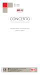
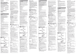
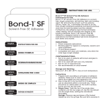
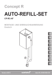
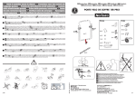
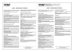
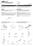
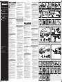
USA
ENGLISH
Safety
ContiPressureCheck
TM
■■
//
USA
CZ
P
RO
Quick-Start Guide for
Installation
Krátký návod k instalaci
■■
■■
■■
■■
Instruções breves de
instalação
Ghid succint de
instalare
■■
This quick-start guide is intended only to
illustrate the main installation steps. It presupposes knowledge of the comprehensive
installation instructions. Therefore be sure
to read also the comprehensive installation
instructions for the system.
Observe all the safety precautions in the installation instructions!
All work may only be carried out by appropriately qualified staff.
Observe the vehicle manufacturer‘s safety instructions.
During installation, wear the necessary personal
protective equipment for the particular operation.
Observe the warnings on the containers of the
cleansing agent and adhesive.
In view of the risk of short-circuit, always switch
off all electrical consumers and disconnect the
minus terminal of the battery before carrying
out work on the vehicle electrical system.
Components and accessories (A)
●● CCU (Central Control Unit) (Fig. A1)
●● Auxiliary receiver (Fig. A2)
●● Impact guard (aux. receiver) (Fig. A3)
●● Display (Fig. A4)
●● Tire sensor (Fig. A5)
●● Rubber container (Fig. A6)
●● Pressure control indicator (A7)
●● Diagnostic cable (Fig. A8)
●● Hand-held tool (Fig. A9)
●● Wiring harnesses A (0.75 m), B (3.0 m), C (9.0 m),
10. In the distributor box, fasten the fuse supplied
to the plus cable (red) using the cable shoes in
the installation kit.
11. In the distributor box, identify terminals U_bat
and GND. Pay attention to the special instructions in the vehicle operating manual.
12. Connect the red cable (incl. fuse) to terminal
U_bat and the black cable to GND.
Installing the tire sensors (E)
Work steps:
1. Select the attachment position for the tire sensor in the tire (Fig. E1).
2. Pretreatment of the bonding surface:
For cleaning the bonding surfaces:
Pay attention to the following cleaning and assembly instructions.
►► As a result of internal tests performed by Continental Reifen Deutschland GmbH, the use of
Liquidbuffer from Tiptop is recommended (see
Installation instructions) for cleaning the adhesive surfaces.
►► If any other products are used for cleaning,
Continental Reifen Deutschland GmbH cannot
guarantee that adhesion is sufficient for the application.
ATTENTION
►► Brake cleaner or similar substances may never
be used for cleaning the adhesive surfaces since
this will impair the adhesive process. Possible
consequences: The tire sensor and the rubber
container can become unstuck and damage the
tire in the long term.
►► Furthermore, the use of brake cleaner can damage the tire.
D (7.0 m), F (14.0 m) + G (7.0 m) and H (7.0 m)
(Fig. A10)
Tool (B)
ContiPressureCheck installation and use of:
www.contipressurecheck.com
(Fig. B2)
* Tools are not included in the scope of supply.
Electrical installation HGV/bus (C)
www.contipressurecheck.com
www.continental-truck-tires.com
www.continental-corporation.com
KIA_CPC_0514_A2-A
Continental Reifen Deutschland GmbH
Büttnerstraße 25
30165 Hannover
Germany
3.
4.
5.
6.
Electrical installation Trailer/
semi-trailer (D)
Position of the components on the trailer (Fig. D1)
Block circuit diagram (Fig. D2)
Work steps:
1. Install the CCU at axle height in the middle between the axles.
2. On complex trailers (e.g. more than 3 axles),
use of the auxiliary receiver is recommended.
In this case the central control unit should be
positioned as close as possible to the first axle,
and the auxiliary receiver as close as possible to
the last axle.
3. Then push the impact guard (Fig. A3) over the
auxiliary receiver (Fig. A2), inserting the latching hooks into the holder until they engage
audibly.
4. Installation and adjustment of the pressure control indicator.
5. Lay wiring harness H from the CCU to the auxiliary receiver (if used). Connect the plug side
of the CCU first, then lay the cable along the existing wiring harness of the trailer and connect
the plug side of the auxiliary receiver.
6. Connect the plug end of wiring harness F+G to
the CCU.
7. Lay wiring harness G along the existing wiring
harness of the vehicle to the pressure control
indicator.
8. Lay wiring harness F from the CCU to the distributor box.
9. Find a suitable cable leadthrough in the distributor box, thread in the cable and shorten as
required.
7.
2.1 Wet the bonding surface to be cleaned
with the cleansing agent (Fig. E2).
2.2 Then roughen the bonding surface with
several offset passes with the scraper, applying slight pressure (Fig. E3).
2.3 Then thoroughly clean the bonding surface
using the cleaning cloth, wiping only in one
direction and always using a clean area of
the cloth (Fig. E4).
2.4 Repeat steps 2.1 to 2.3 at least 2x.
2.5 Allow the cleaned surface to dry for approx. 3 minutes.
Insert the tire sensor into the rubber container.
(Note: The tire sensor is normally supplied preassembled in the rubber container - cf. Fig. E7)
3.1 Fold over the sealing lip of the rubber container (Fig. E5).
3.2 Wet the base surface with mounting paste.
3.3 Fit the tire sensor (Fig. E6).
3.4 Fold the sealing lip up again (Fig. E7).
Inserting the rubber container into the pressing
tool.
4.1 Place the inlay part into the upper part of
the pressing tool (Fig. E8).
4.2 Place the rubber container in the pressing
tool so that the two direction of rotation
arrows on the tire sensor correspond with
those on the pressing tool (Fig. E9).
4.3 Check that the rubber container is flush in
the pressing tool all round (Fig. E10).
Cleaning the rubber container.
5.1 Spray cleansing agent onto the cleaning
cloth and thoroughly wet the bonding surface to be cleaned with the cleansing agent
(Fig. E11).
5.2 Then thoroughly clean the bonding surface
using the cleaning cloth, wiping only in one
direction and always using a clean area of
the cloth.
5.3 Allow the cleaned surface to dry for approx. 3 minutes.
Cementing in the rubber container with integral
tire sensor.
6.1 Apply „1 mark“ of the special adhesive to
the bonding surface of the rubber container (Fig. E12).
6.2 Spread the special adhesive over the rubber container using the spatula.
6.3 Position pressing tool with tire sensor in
the tire so that the direction of rotation arrows are pointing in running direction.
6.4 Then press the rubber container vertically
onto the cleaned bonding surface using
the pressing tool (approx. 45 seconds with
a weight of at least 5 kg) (Fig. E13).
Function check of the tire senor
7.1 Switch on hand-held tool (Fig. A9).
7.2 Select menu item „Tire sensor activation“.
7.3 Hold the hand-held tool against the sensor
(Fig. E14).
If „Tire sensor OK“ is displayed, the tire can
be fitted.
Startup of the system
Work steps:
1. Switch on hand-held tool (Fig. A9).
2. Select menu item „Installation / New Installation“.
3. Follow the instructions on the hand-held tool.
4. Teach-in of the tire sensors and configuration
of the CCU.
4.1 Hold the hand-held tool in the wheel position shown and against the side wall and
follow the animation on the display.
Note: The hand-held tool can remain on the
outer of the twin tires when reading out
the tire sensor of the inner twin tire.
4.2 Connect the hand-held tool to the display
(HGV) or to the diagnostic plug of the pressure control indicator (trailer) using the
diagnostic cable (Fig. A8).
4.3 Transferring the data to the CCU.
5. After successful configuration, switch off the
CCU for at least 30 seconds. Then carry out a
test drive to check the system.
Česky
Bezpečnost
►► Consider the additional/current instructions on
●● Cleaning cloth* (Fig. B3)
●● Pressing tool (Fig. B4)
●● Cyberbond 2250 special adhesive (Fig. B5)
●● Spatula (Fig. B6)
●● Cleaning scraper* (Fig. B7)
A2C81582600 - 17340470000
CZ
NOTE
●● Protective gloves* (Fig. B1)
●● Cleanser* (e.g. TipTop Liquid Buffer 500 ml)
Position of the components on the HGV (Fig. C1)
Block circuit diagram (Fig. C2)
Connections (Fig. C3)
Work steps:
1. Install the CCU at axle height.
HGV: Mid-way between the front axle and the
first rear axle.
Bus: Front axle area (preferably in the trunk)
2. Installation of the auxiliary receiver.
HGV: In the middle at the rear of the vehicle
Bus: Rear axle area (preferably in the trunk)
3. Lay wiring harness D from the CCU to the auxiliary receiver. Connect the plug side of the CCU
first, then lay the cable along the existing wiring
harness of the vehicle and connect the plug
side of the auxiliary receiver.
4. Then push the impact guard (Fig. A3) over the
auxiliary receiver (Fig. A2), inserting the latching hooks into the holder until they engage
audibly.
5. Lay wiring harness C from the CCU to the driver‘s cab. Connect the plug end of wiring harness
C to the CCU and lay the wiring harness to the
vehicle fuse box.
6. Install displays in the driver‘s cab using the
bracket supplied.
7. Lay wiring harness B from the display to the
fuse box. Connect the plug end of wiring harness B to the display and lay the cable behind
the instrument panel from the display to the
fuse box.
8. Connect the two CAN terminals (brown/white)
of wiring harnesses C and B with cable shoes.
9. Lay wiring harness A from the fuse box to
wiring harness B and C. The integrated fuse
remains in wiring harness A.
10. Join conductors KL 15 (red) and 31 (black) of
wiring harnesses A, B and C together using Y
connectors.
11. Connect ignition terminal 15 (red) and ground
cable terminal 31 (black) to the fuse box.
HGV/bus:
5.1 Connect the hand-held tool to the display (Fig. A4) using the diagnostic cable
(Fig. A8).
5.2 Select menu item „Installation / Test drive
HGV/bus“.
5.3 Start test drive.
5.4 A progress bar appears on the hand-held
tool. The test drive can be terminated
when the progress bar reaches the end.
Trailer/semi-trailer
5.1 Disconnect the diagnostic plug from the
pressure control indicator.
5.2 Connect the hand-held tool to the diagnostic plug.
5.3 Select menu item „Installation / Test drive
trailer / Initialization“.
5.4 Disconnect the hand-held tool.
5.5 Connect the diagnostic plug to the pressure control indicator.
5.6 Start test drive.
5.7 The test drive can be terminated when the
pressure control indicator gives off a continuous signal for 60 seconds.
5.8 Connect the hand-held tool to the diagnostic plug again and select menu item „Installation / Test drive trailer / Evaluation“.
6. Read out and print out the result of the test
drive.
7. During later operation:
After replacing or changing the position of one
or more tire sensors, reset the telegram counter
in the display.
■■
■■
■■
■■
■■
■■
Tento krátký návod slouží pouze k znázornění hlavních kroků instalace. Nezbytně
předpokládá znalosti podrobného návodu
na instalaci. Pročtěte si proto v každém
případě také podrobný návod na instalaci k
systému.
Dodržujte všechny bezpečnostní pokyny v návodu na instalaci!
Veškeré práce smí provádět výhradně kvalifikovaný personál.
Dodržujte bezpečnostní pokyny výrobce vozidla!
Při instalaci používejte osobní ochranné vybavení, nutné pro příslušné práce.
Dodržujte výstražné pokyny na nádobách čistícího prostředku a lepidla.
Vzhledem k nebezpečí zkratu vypněte před pracemi na elektrické instalaci vozidla vždy všechny
elektrické spotřebiče a odsvorkujte minusový
pól akumulátoru.
Konstrukční díly a příslušenství (A)
●● CCU (Central Control Unit - Centrální řídící pří-
11. Připojte svorku 15 zapalování (červená) a zemnící vodič svorku 31 (černá) na pojistkové skříni.
D (7,0 m), F (7,0 m) + G (7,0 m) a H (7,0 m) (obr.
A10)
Nářadí (B)
●● Ochranné rukavice (obr. B1)
●● Čistič* (např. kapalný pufr TipTop 500 ml) (obr.
Umístění konstrukčních dílů na přívěsu (obr. D1)
Blokové schéma zapojení (obr. D2)
Pracovní kroky:
1. Montáž CCU uprostřed mezi nápravami ve výšce náprav.
2. U komplexních přívěsů (např. více než 3 nápravy) se doporučuje použití přídavného přijímače.
V tomto případě se umístí centrální řídící přístroj co možno blízko v oblasti první nápravy a
přídavný přijímač co nejblíže v oblasti poslední
nápravy.
3. Potom přehrňte ochranu proti nárazu (obr.3)
přes přídavný přijímač (obr. A2), přitom zaveďte
zajišťovací háky do držáku, až zaskočí.
4. Montáž a vyrovnání kontrolního ukazatele tlaku.
5. Uložte kabelový svazek H od CCU k přídavnému
přijímači (pokud je použit). Zástrčkovou stranu
CCU spojte nejprve, uložte kabel na stávajícím
kabelovém svazku přívěsu a spojte zástrčkovou
stranu přídavného přijmače.
6. Spojte zástrčkovou stranu kabelového svazku
F+G s CCU.
7. Uložte kabelový svazek G na stávajícím kabelovém svazku vozidla ke kontrolnímu ukazateli
tlaku.
8. Uložte kabelový svazek F od CCU k rozvodné
skříni.
9. Vyhledejte vhodnou kabelovou průchodku v
rozvodné skříni, kabel zasuňte a vhodně zkraťte.
10. Instalujte v rozvodné skříni přiloženou pojistku
na plusový kabel (červený) s přiloženými koncovkami kabelu.
11. Vyhledejte v rozvodné skříni přípojky U_bat a
GND. Přitom respektujte zvláštní pokyny z příručky pro obsluhu vozidla.
12. Spojte červený vodič (včet. pojistky) s přípojkou
U_bat a černý s GND.
A8
A9
A3
A5
A4
A7
A6
A10
D
A
B
C
G
H
F+G
F
B1
B3
B2
B4
B5
C1
B6
C2
B7
B
C
Montáž snímačů pneumatik (E)
Pracovní kroky:
1. Zvolte polohu lepení pro snímač pneumatik v
pneumatice (obr. E1).
2. Příprava lepící plochy:
D
A
K čištění lepicích ploch:
Respektujte následující pokyny k čištění a montáži.
►► Na základě vlastního provedeného testu doporučuje společnost Continental Reifen Deutschland
GmbH používat k čištění lepených ploch kapalný
pufr od firmy Tiptop (viz návod k instalaci).
►► Při použití jiných produktů k čištění nemůže společnost Continental Reifen Deutschland GmbH
zaručit, že lepení bude v daném případě použití
dostatečné.
C3
KL 15
(IGN)
KL 31
(GND)
BR/BN
RT/RD
SW/BK
WS/WH
POZOR
►► Za žádných okolností se k čištění lepených ploch
nesmí používat čističe brzd ani podobné látky,
protože mohou nepříznivě působit na proces
lepení. Možné důsledky: Snímač pneumatiky
včetně pryžového obalu se může uvolnit a trvale
poškodit pneumatiku.
►► Použitím čističe brzd může navíc dojít k poškození pneumatiky.
D1
D2
POKYN
►► Zohledněte další / aktualizované pokyny k insta-
H
laci a používání ContiPressureCheck:
www.contipressurecheck.com
B2)
●● Čistící utěrka* (obr. B3)
●● Přítlačný nástroj (obr. B4)
●● Speciální lepidlo Cyberbond 2250 (obr. B5)
●● Stěrka (obr. B6)
●● Čistící škrabka (obr. B7)
* Nářadí není součástí dodávky.
Elektrická instalace
Nákladní automobil/bus (C)
Umístění konstrukčních dílů na nákladním automobilu (obr. C1)
Blokové schéma zapojení (obr. C2)
Propojení (obr. C3)
Pracovní kroky:
1. Montáž CCU ve výšce nápravy.
Nákladní automobil: Uprostřed mezi přední nápravou a první zadní nápravou.
Bus: Oblast přední nápravy (přednostně v zavazadlovém prostoru)
2. Montáž přídavného přijímače.
Nákladní automobil: Uprostřed na zadní části
vozidla.
Bus: Oblast zadní nápravy (přednostně v zavazadlovém prostoru).
3. Uložte kabelový svazek od CCU k přídavnému
přijímači. Nejprve spojte zástrčkovou stranu
CCU, uložte kabel na stávajícím kabelovém
svazku vozidla a spojte zástrčkovou stranu přídavného přijímače.
4. Potom přehrňte ochranu proti nárazu (obr.3)
přes přídavný přijímač (obr. A2), přitom zaveďte
zajišťovací háky do držáku, až zaskočí.
5. Uložte kabelový svazek od CCU ke kabině
řidiče. Zástrčkovou stranu kabelového svazku
C spojte s CCU a kabelový svazek uložte až k
pojistkové skříňce vozidla.
6. Displeje instalujte v kabině řidiče s pomocí společně dodaného držáku.
7. Uložte kabelový svazek B od displeje k pojistkové skříňce. Zástrčkovou stranu kabelového
svazku B spojte s displejem a uložte kabel za
přístrojovou deskou od displeje k pojistkové
skříňce.
8. Obě přípojky CAN (hnědá/bílá) kabelového
svazku C a B spojte s koncovkami kabelu.
9. Uložte kabelový svazek A od pojistkové skříňky
ke kabelovému svazku B a C. Integrovaná pojistka zůstane v kabelovém svazku A.
10. Vodiče KL 15 (červený) a 31 (černý) kabelových
svazků A, B a C spojte vždy společně s konektory Y.
A2
Elektrická instalace
Přívěs/sedlový návěs (D)
stroj) (obr. A1)
●● Přídavný přijímač (obr. A2)
●● Ochrana proti nárazu (přídavný přijímač) (obr.A3)
●● Displej (obr. A4)
●● Snímač pneumatiky (obr. A5)
●● Pryžový obal (obr. A6)
●● Kontrolní ukazatel tlaku (A7)
●● Diagnostický kabel (obr. A8)
●● Ruční čtečka (obr. 9)
●● Kabelové svazky A (0,75 m), B (3,0 m), C (9,0 m),
A1
3.
4.
5.
6.
2.1 Smáčejte lepené plochy čistícím prostředkem (obr. E2).
2.2 Potom lepící plochu několikrát škrabkou
pod lehkým tlakem očistěte (obr. E3).
2.3 Následně lepící plochu čistící utěrkou
důkladně vyčistěte, přitom stírejte jen v
jednom směru a stále používejte čisté části
utěrky (obr. E4).
2.4 Kroky 2.1 až 2.3 nejméně 2 x zopakujte.
2.5 Očištěnou plochu nechte po dobu cca 3
minut odvětrat.
Vložení snímače pneumatiky do pryžového
obalu. (Poznámka: Zpravidla se dodává snímač
pneumatiky předem smontovaný v pryžovém
obalu - viz obr. E7).
3.1 Přehrňte těsnící lem pryžového obalu
(obr. E5).
3.2 Základní plochu pokryjte montážní pastou.
3.3 Nasaďte snímač pneumatiky (obr. E6).
3.4 Těsnící lem opět vyhrňte nahoru (obr.E7).
Uložení pryžového obalu do přítlačného nástroje.
4.1 Vkládací část vložte do horní části přítlačného nástroje (obr. E8).
4.2 Vložte pryžový obal do přítlačného nástroje tak, aby obě šipky směru otáčení
snímače pneumatik souhlasily se šipkami
přítlačného nástroje (obr. E9).
4.3 Dejte pozor na lícovanou polohu po celém
obvodu pryžového obalu v přítlačném nástroji (obr. E10).
Čištění pryžového obalu
5.1 Nastříkejte čistící prostředek na čistící utěrku a smáčejte celou čištěnou lepící plochu
čistícím prostředkem (obr. E11).
5.2 Potom lepící plochu čistící utěrkou důkladně vyčistěte, přitom stírejte jen v jednom
směru a stále používejte čisté části utěrky.
5.3 Očištěnou plochu nechte po dobu cca 3
minut odvětrat.
Vlepení pryžového obalu s integrovaným snímačem pneumatik.
6.1 Naneste na lepící plochu pryžového obalu
„1 dílek“ speciálního lepidla (obr. E12).
6.2 Rozložte stěrkou speciální lepidlo na pryžovém obalu.
6.3 Vyrovnejte přítlačný nástroj se snímačem
pneumatik v pneumatice tak, aby směřovaly šipky směru otáčení ve směru chodu.
6.4 Potom přitlačte pryžový obal pomocí přítlačného nástroje svisle na očištěnou plochu (cca 45 sekund s hmotností min.
5 kg) (obr. E13).
F+G
F+G
E1
E2
E3
E4
E5
E6
E7
E8
E9
E10
E12
E13
E14
E11
7. Kontrola funkce snímače pneumatik.
7.1 Zapněte ruční čtečku (obr. A9).
7.2 Zvolte bod menu „Aktivování snímače
pneumatik“.
7.3 Podržte ruční čtečku u snímače (obr. E14).
Při hlášení „Snímač pneumatik v pořádku“
je možno pneumatiku namontovat.
Uvedení systému do provozu
Pracovní kroky:
1. Zapněte ruční čtečku (obr. A9).
2. Zvolte bod menu „Instalace/Nová instalace“.
3. Sledujte pokyny ruční čtečky.
4. Zaučení snímačů pneumatik a konfigurace
CCU.
4.1 Držte ruční čtečku na udané poloze kola
a na boku sledujte podle animace na obrazovce.
Upozornění: K načtení snímače pneumatik vnitřní pneumatiky dvojitého osazení
může zůstat ruční čtečka na vnější pneumatice.
4.2 Připojte ruční čtečku pomocí diagnostického kabelu (obr. A8) na displeji (nákladní
automobil) nebo na diagnostickém konektoru na kontrolním ukazateli tlaku (přívěs).
4.3 Přehrání dat na CCU.
5. Po úspěšné konfiguraci CCU na dobu min. 30
sekund vypněte. Potom se provede zkušební
jízda k přezkoušení systému.
Nákl.auto/bus:
5.1 Spojte ruční čtečku diagnostickým kabelem (obr. A8) s displejem (obr. A4).
5.2 Zvolte bod menu „Instalace/Zkušební jízda
nákl. auto/BUS“.
5.3 Zahajte zkušební jízdu.
5.4 Na ruční čtečce se objeví postupový sloupec. Zkušební jízdu je možno skončit, když
sloupec proběhne.
Přívěs/sedlový návěs:
5.1 Odpojte diagnostický konektor od kontrolního ukazatele tlaku.
5.2 Připojte ruční čtečku na diagnostický konektor.
5.3 Zvolte bod menu „Instalace/Zkušební jízda
přívěs/inicializace“.
5.4 Odpojte ruční čtečku.
5.5 Spojte diagnostický konektor s kontrolním
ukazatelem tlaku.
5.6 Zahajte zkušební jízdu.
5.7 Zkušební jízda může skončit, když předává kontrolní ukazatel tlaku po dobu 60
sekund trvalý signál.
5.8 Spojte znovu ruční čtečku s diagnostickým
konektorem a proveďte bod menu „Instalace /Zkušební jízda přívěs /Vyhodnocení“.
6. Výsledek zkušební jízdy načtěte a vytiskněte.
7. V pozdějším provozu.
Po výměně nebo změně polohy jednoho nebo
několika snímačů pneumatik resetujte stav
čítače telegramů na displeji.
Português
P
Segurança
■■
■■
■■
■■
■■
■■
Estas instruções breves servem unicamente para demonstrar os passos de instalação
mais importantes. Elas pressupõem conhecimentos obrigatórios das instruções
detalhadas de instalação. Por isso, leia
sempre também as instruções detalhadas
de instalação do sistema.
Observe todas as instruções de segurança nas
instruções de instalação!
Todos os trabalhos só podem ser realizados por
pessoal com a respetiva qualificação.
Observe as instruções de segurança do fabricante do veículo!
Use o equipamento de proteção pessoal necessário para realizar todos os trabalhos durante a
instalação.
Observe os avisos colocados nos recipientes do
produto de limpeza e da cola.
Devido ao perigo de curto-circuito, desligar
sempre todas as cargas elétricas e separar o
polo negativo da bateria, antes de realizar quaisquer trabalhos no sistema elétrico do veículo.
Componentes e acessórios (A)
●● CCU (Central Control Unit - aparelho central de
comando) (Fig. A1)
●● Recetor auxiliar (Fig. A2)
●● Proteção de choque (recetor auxiliar) (Fig. A3)
●● Display (Fig. A4)
●● Sensor de pneus (Fig. A5)
●● Recipiente de borracha (Fig. A6)
●● Indicador do controlo da pressão (A7)
●● Cabo de diagnóstico (Fig. A8)
●● Aparelho de leitura manual (Fig. A9)
●● Conjuntos de cabos A (0,75 m), B (3,0 m), C
(9,0 m), D (7,0 m), F (7,0 m) + G (7,0 m) e H (7,0
m) (Fig. A10)
Ferramentas (B)
●● Luvas de proteção* (Fig. B1)
●● Produto de limpeza* (p. ex. TipTop Liquid Buffer
500 ml) (Fig. B2)
●● Pano de limpeza* (Fig. B3)
●● Ferramenta de pressão (Fig. B4)
●● Cola especial Cyberbond 2250 (Fig. B5)
●● Espátula (Fig. B6)
●● Raspador de limpeza* (Fig. B7)
* Ferramentas não incluídas no volume de fornecimento.
Instalação elétrica
Camião/Autocarro (C)
Posição dos componentes no camião (Fig. C1)
Diagrama de blocos (Fig. C2)
Ligações (Fig. C3)
Passos de trabalho:
1. Montagem do CCU à altura do eixo.
Camião: ao centro entre o eixo dianteiro e o
primeiro eixo traseiro.
Autocarro: área do eixo dianteiro (de preferência no porta-bagagens)
2. Montagem do recetor auxiliar.
Camião: ao centro na traseira do veículo.
Autocarro: área do eixo traseiro (de preferência no porta-bagagens).
3. Instalar o conjunto de cabos D do CCU para o
recetor auxiliar. Ligar primeiro o lado da ficha
elétrica do CCU, instalar o cabo no conjunto
de cabos existente do veículo e ligar o lado da
ficha elétrica do recetor auxiliar.
4. De seguida, colocar a proteção de choque
(Fig. A3) sobre o recetor auxiliar (Fig. A2), introduzindo os ganchos de bloqueio no suporte
até que eles encaixem.
5. Instalar o conjunto de cabos C do CCU para a
cabina. Ligar o lado da ficha elétrica do conjunto de cabos C ao CCU e instalar o conjunto de
cabos até à caixa de fusíveis do veículo.
6. Instalar os displays na cabina com o auxílio do
suporte fornecido.
7. Instalar o conjunto de cabos B do display para
a caixa de fusíveis. Ligar o lado da ficha elétrica
do conjunto de cabos B ao display e instalar o
cabo atrás do painel de instrumentos do display até à caixa de fusíveis.
8. Ligar ambas as ligações CAN (castanho/branco)
do conjunto de cabos C e B aos terminais do
cabo.
9. Instalar o conjunto de cabos A da caixa de fusíveis para o conjunto de cabos B e C. O fusível
integrado mantém-se no conjunto de cabos A.
10. Ligar, uns aos outros, os condutores KL 15 (vermelho) e 31 (preto) dos conjuntos de cabos A,
B e C cada um com conectores Y.
11. Ligar o borne 15 ignição (vermelho) e o cabo
de terra borne 31 (preto) à caixa de fusíveis.
Instalação elétrica
Reboque/Semirreboque (D)
Posição dos componentes no reboque (Fig. D1)
Diagrama de blocos (Fig. D2)
Passos de trabalho:
1. Montagem do CCU no centro entre os eixos à
altura do eixo.
2. Nos reboques complexos (p. ex. mais de 3 eixos), recomenda-se a utilização do recetor auxiliar. Neste caso, o aparelho central de comando deve ser posicionado o mais perto possível
da zona do primeiro eixo e o recetor auxiliar o
mais perto possível da zona do último eixo.
3. De seguida, colocar a proteção de choque
(Fig. A3) sobre o recetor auxiliar (Fig. A2), introduzindo os ganchos de bloqueio no suporte
até que eles encaixem.
4. Montagem e regulação do indicador do controlo da pressão
5. Instalar o conjunto de cabos H do CCU para o
recetor auxiliar (se utilizado). Ligar primeiro o
lado da ficha elétrica do CCU, instalar o cabo no
conjunto de cabos existente do reboque e ligar
o lado da ficha elétrica do recetor auxiliar.
6. Ligar o lado da ficha elétrica do conjunto de
cabos F+G ao CCU.
7. Instalar o conjunto de cabos G no conjunto de
cabos existente do veículo para o indicador do
controlo da pressão.
8. Instalar o conjunto de cabos F do CCU para a
caixa de distribuição.
9. Procurar uma passagem de cabos apropriada
na caixa de distribuição, passar o cabo e encurtá-lo adequadamente.
10. Na caixa de distribuição, colocar o fusível
fornecido no cabo positivo (vermelho) com os
terminais do cabo existentes.
11. Procurar as ligações U_bat e GND na caixa de
distribuição. Observar aqui as instruções especiais do manual de utilização do veículo.
12. Conectar o cabo vermelho (incl. fusível) à ligação U_bat e o cabo preto à ligação GND.
Montagem dos sensores de
pneus (E)
Passos de trabalho:
1. Selecionar a posição de aderência para o sensor de pneus no pneu (Fig. E1).
2. Pré-tratamento da superfície de goma:
Para limpeza das superfícies de goma:
Tenha em conta as seguintes instruções de limpeza
e montagem.
►► A Continental Reifen Deutschland GmbH recomenda a utilização de líquido Buffer da empresa
Tiptop (consultar as instruções de instalação)
para a limpeza de superfícies de goma, com
base na realização de testes próprios.
►► Se forem utilizados outros produtos para limpeza, a Continental Reifen Deutschland GmbH não
garante que a aderência seja suficiente para o
caso de aplicação.
ATENÇÃO
►► Nunca utilize limpa travões ou substâncias
semelhantes para a limpeza de superfícies de
goma, porque desse modo o processo de aderência pode ser prejudicado. Consequências
possíveis: o sensor dos pneus e o recipiente de
borracha podem soltar-se e acabar por danificar
os pneus.
►► Além disso, a utilização do limpa travões pode
danificar os pneus.
NOTA
►► Tenha em atenção as instruções adicionais/
atuais relativas à instalação e utilização de ContiPressureCheck em:
www.contipressurecheck.com
2.1 Pulverizar a superfície de goma a limpar
com o produto de limpeza (Fig. E2).
2.2 De seguida, remover várias vezes, em várias posições, a superfície de goma com o
raspador, exercendo uma leve pressão
(Fig. E3).
2.3 De seguida, limpar bem a superfície de
goma com o pano de limpeza, limpando
apenas num sentido e utilizando sempre
as partes limpas do pano (Fig. E4).
2.4 Repetir, no mínimo, 2 vezes os passos 2.1
a 2.3.
2.5 Deixar a superfície limpa ventilar durante
aprox. 3 minutos.
3. Aplicação do sensor de pneus no recipiente de
borracha. (Nota: geralmente, o sensor de pneus
é fornecido previamente montado no recipiente de borracha - compar. Fig. E7)
3.1 Dobrar o lábio de vedação do recipiente
de borracha (Fig. E5).
3.2 Humedecer a superfície de base com pasta de montagem.
3.3 Colocar sensor de pneus (Fig. E6).
3.4 Virar o lábio de vedação novamente para
cima (Fig. E7).
4. Aplicação do recipiente de borracha na ferramenta de pressão.
4.1 Colocar o componente de inserção na
parte superior da ferramenta de pressão
(Fig. E8).
4.2 Colocar o recipiente de borracha na ferramenta de pressão, de forma a que ambas
as setas do sentido de rotação do sensor
de pneus correspondam às setas da ferramenta de pressão (Fig. E9).
4.3 Ter em atenção o posicionamento adequado do recipiente de borracha para que o
mesmo se encaixe corretamente na ferramenta de pressão (Fig. E10).
5. Limpeza do recipiente de borracha.
5.1 Pulverizar o pano de limpeza com produto
de limpeza e humedecer toda a superfície
de goma a limpar com o produto de limpeza (Fig. E11).
5.2 De seguida, limpar bem a superfície de
goma com o pano de limpeza, limpando
apenas num sentido e utilizando sempre
as partes limpas do pano.
5.3 Deixar a superfície limpa ventilar durante
aprox. 3 minutos.
6. Colagem do recipiente de borracha com o sensor de pneus integrado.
6.1 Aplicar “1 fio parcial” da cola especial na
superfície de goma do recipiente de borracha (Fig. E12).
6.2 Espalhar a cola especial com a espátula no
recipiente de borracha.
6.3 Alinhar a ferramenta de pressão com o
sensor de pneus no pneu, de forma a que
as setas do sentido de rotação apontem na
direção de andamento.
6.4 De seguida, pressionar o recipiente de
borracha com o auxílio da ferramenta de
pressão verticalmente contra a superfície
de goma limpa (aprox. 45 segundos com
um peso mín. de 5 kg) (Fig. E13).
7. Verificação do funcionamento do sensor de
pneus.
7.1 Ligar o aparelho de leitura manual (Fig.
A9).
7.2 Selecionar a opção de menu “Ativação do
sensor de pneus”.
7.3 Colocar o aparelho de leitura manual em
frente ao sensor (Fig. E14).
A mensagem “Sensor de pneus OK” indica
que o pneu pode ser montado.
Colocação em funcionamento do
sistema
Passos de trabalho:
1. Ligar o aparelho de leitura manual (Fig. A9).
2. Selecionar a opção de menu “Instalação/Nova
instalação”.
3. Seguir as instruções do aparelho de leitura
manual.
4. Codificação dos sensores de pneus e configuração do CCU.
4.1 Colocar o aparelho de leitura manual em
frente à posição de roda indicada e seguir
na parede lateral, de acordo com a animação no ecrã.
Nota: para ler o sensor de pneus do pneu
duplo interior, o aparelho de leitura manual pode ser colocado em frente ao pneu
duplo exterior.
4.2 Ligar o aparelho de leitura manual através
do cabo de diagnóstico (Fig. A8) no display
(camião) ou no conector de diagnóstico
do indicador do controlo da pressão (reboque).
4.3 Transferir os dados para o CCU.
5. Após a configuração bem sucedida, desligar o
CCU durante, no mínimo, 30 segundos. Depois
é realizado um test drive para a verificação do
sistema.
Camião/autocarro:
5.1 Ligar o aparelho de leitura manual através
do cabo de diagnóstico (Fig. A8) ao display
(Fig. A4).
5.2 Selecionar a opção de menu “Instalação/
Test Drive Camião/Autocarro”.
5.3 Iniciar o test drive.
5.4 O aparelho de leitura manual apresenta
uma barra de evolução. O test drive pode
ser concluído, quando a barra tiver desaparecido.
Reboque/semirreboque:
5.1 Soltar o conector de diagnóstico do indicador do controlo da pressão.
5.2 Ligar o aparelho de leitura manual ao conector de diagnóstico.
5.3 Selecionar a opção de menu “Instalação/
Test Drive Reboque/Iniciação”.
5.4 Soltar o aparelho de leitura manual.
5.5 Ligar o conector de diagnóstico ao indicador do controlo da pressão.
5.6 Iniciar o test drive.
5.7 O test drive pode ser concluído, se o indicador do controlo da pressão emitir um
sinal contínuo de 60 segundos.
5.8 Ligar novamente o aparelho de leitura
manual ao conector de diagnóstico e executar a opção de menu “Instalação /Test
Drive Reboque/Análise”.
6. Ler e imprimir o resultado do test drive.
7. Na operação posterior:
Após a substituição ou mudança de posição de
um ou vários sensores de pneus, repor o estado do contador dos telegramas no display.
RO
Română
Siguranţă
■■
■■
■■
■■
■■
■■
Acest ghid succint serveşte exclusiv ilustrării celor mai importanţi paşi de instalare. El
presupune în mod obligatoriu cunoaşterea
manualului de instalare detaliat. Din acest
motiv trebuie să citiţi în orice caz şi manualul de instalare detaliat al sistemului.
Respectaţi toate indicaţiile de siguranţă din manualul de instalare!
Toate lucrările se vor realiza numai de către personal calificat.
Respectaţi indicaţiile de siguranţă ale producătorului autovehiculului!
În timpul instalării purtaţi echipamentul individual de protecţie necesar pentru lucrările
respective.
Respectaţi indicaţiile de avertizare de pe recipientele cu detergent şi adeziv.
Din cauza pericolului de scurtcircuit, înainte de
lucrările la sistemul electric al autovehiculului
trebuie să dezactivaţi întotdeauna toţi consumatorii electrici şi să decuplaţi polul minus al
bateriei.
Componente şi accesorii (A)
●● CCU (Central Control Unit - unitate de comandă
centrală) (fig. A1)
●● Receptor suplimentar (fig. A2)
●● Protecţie anti-şoc (receptor suplim.) (fig. A3)
●● Ecran (fig. A4)
●● Senzor pneuri (fig. A5)
●● Suport de cauciuc (fig. A6)
●● Indicator de control al presiunii (A7)
●● Cablu de diagnoză (fig. A8)
●● Cititor portabil (fig. A9)
●● Fascicule de cabluri A (0,75 m), B (3,0 m), C (9,0
6. Conectaţi partea fişabilă a fasciculului de cabluri F+G la CCU.
7. Pozaţi fasciculul de cabluri G lângă fasciculul
de cabluri existent deja la autovehicul până la
indicatorul de control al presiunii.
8. Pozaţi fasciculul de cabluri F de la CCU la panoul de distribuţie.
9. Căutaţi un orificiu adecvat de trecere a cablurilor în panoul de distribuţie, treceţi cablul prin
acesta şi scurtaţi cablul în mod corespunzător.
10. În panoul de distribuţie montaţi siguranţa inclusă în setul de livrare la cablul plus (roşu), cu
papucii de cablu livraţi.
11. Căutaţi în panoul de distribuţie bornele U_bat
şi GND. Respectaţi în această privinţă indicaţiile
speciale din manualul de utilizare al autovehiculului.
12. Conectaţi cablul roşu (inclusiv siguranţa) la borna
U_bat şi cablul negru la GND.
Montarea senzorilor pentru
pneuri (E)
Paşi de lucru:
1. Alegerea locului unde se va lipi senzorul în
pneu (fig. E1).
2. Tratamentul prealabil al suprafeţei de lipit:
Pentru curăţarea suprafeţelor de lipit:
Respectaţi următoarele instrucţiuni privind curăţarea şi montarea.
►► Continental Reifen Deutschland GmbH recomandă
pe baza testelor efectuate intern utilizarea soluţiei
de curăţare Liquid Buffer de la firma Tip Top (vezi
manualul de instalare) pentru curăţarea suprafeţelor de lipire.
►► Dacă se folosesc alte produse pentru curăţare,
Continental Reifen Deutschland GmbH nu poate
garanta lipirea suficientă pentru cazul concret
de aplicare.
m), D (7,0 m), F (7,0 m) + G (7,0 m) şi H (7,0 m)
(fig. A10)
Instrumente (B)
●● Mânuşi de protecţie* (fig. B1)
●● Agent de curăţare* (de ex. TipTop Liquid Buffer
500 ml) (fig. B2)
●● Lavetă* (fig. B3)
●● Sculă de apăsare (fig. B4)
●● Adeziv special Cyberbond 2250 (fig. B5)
●● Spatulă (fig. B6)
●● Racletă de curăţat* (fig. B7)
ATENŢIE
►► Pentru curăţarea suprafeţelor de lipire nu se vor
folosi în niciun caz soluţii de curăţat frâne sau
substanţe asemănătoare, deoarece acestea pot
influenţa negativ procesul de lipire. Urmare posibilă: senzorul de presiune din pneuri se poate
dezlipi împreună cu suportul de cauciuc, iar pe
termen lung acest lucru poate deteriora pneul.
►► Pe lângă acest fapt, utilizarea unei soluţii de curăţat frâne poate deteriora pneul în sine.
INDICAŢIE
* Instrumentele nu sunt incluse în setul de livrare.
Instalare electrică
autocamion/autobuz (C)
Poziţia componentelor la autocamion (fig. C1)
Schemă-bloc (fig. C2)
Conexiuni (fig. C3)
Paşi de lucru:
1. Montarea CCU la înălţimea osiei.
Autocamion: la jumătatea distanţei între osia
faţă şi prima osie spate.
Autobuz: zona osiei faţă (de preferinţă în portbagaj)
2. Montarea receptorului suplimentar.
Autocamion: la centrul hayonului.
Autobuz: zona osiei spate (de preferinţă în
portbagaj).
3. Pozaţi fasciculul de cabluri D de la CCU la
receptorul suplimentar. Conectaţi mai întâi
partea fişabilă a CCU, pozaţi cablul lângă fasciculul de cabluri deja existent la autovehicul
şi conectaţi apoi partea fişabilă a receptorului
suplimentar.
4. Apoi puneţi protecţia anti-şoc (fig. A3) peste
receptorul suplimentar (fig. A2), introducând
cârligul de fixare în suport până când anclanşează.
5. Pozaţi fasciculul de cabluri C de la CCU la
cabina şoferului. Conectaţi partea fişabilă a
fasciculului de cabluri C la CCU şi pozaţi fasciculul de cabluri până la cutia de siguranţe a
autovehiculului.
6. Instalaţi ecranele în cabina şoferului, cu ajutorul suporturilor incluse în setul de livrare.
7. Pozaţi fasciculul de cabluri B de la ecran la cutia
cu siguranţe. Conectaţi partea fişabilă a fasciculului de cabluri B la ecran şi pozaţi cablul prin
spatele panoului de instrumente, de la ecran la
cutia de siguranţe.
8. Conectaţi ambele racorduri CAN (maro/alb) ale
fasciculului de cabluri C şi B cu papuci de cablu.
9. Pozaţi fasciculul de cabluri A de la cutia cu siguranţe la fasciculul de cabluri B şi C. Siguranţa
integrată rămâne în fasciculul de cabluri A.
10. La fiecare dintre fasciculele de cabluri A, B şi C,
legaţi conductorii KL 15 (roşu) şi 31 (negru),
folosind conectori în Y.
11. Conectaţi borna 15 aprindere (roşu) şi cablul
de împământare borna 31 (negru) la cutia de
siguranţe.
Instalare electrică
remorcă/semiremorcă (D)
Poziţia componentelor la remorcă (fig. D1)
Schemă-bloc (fig. D2)
Paşi de lucru:
1. Montarea CCU la înălţimea osiei, la mijlocul distanţei dintre osii.
2. În cazul remorcilor complexe (de ex. mai mult
de 3 osii) se recomandă utilizarea receptorului
suplimentar. În acest caz unitatea de comandă
centrală trebuie poziţionată cât mai aproape de
prima osie, iar receptorul suplimentar cât mai
aproape de ultima osie.
3. Apoi puneţi protecţia anti-şoc (fig. A3) peste
receptorul suplimentar (fig. A2), introducând
cârligul de fixare în suport până când anclanşează.
4. Montarea şi orientarea indicatorului de control
al presiunii.
5. Pozaţi fasciculul de cabluri H de la CCU la
receptorul suplimentar (dacă se utilizează).
Conectaţi mai întâi partea fişabilă a CCU, pozaţi
cablul lângă fasciculul de cabluri deja existent
la remorcă şi conectaţi apoi partea fişabilă a
receptorului suplimentar.
►► Respectaţi indicaţiile suplimentare/actualizate
privind instalarea şi utilizarea ContiPressureCheck de la adresa:
www.contipressurecheck.com
3.
4.
5.
6.
7.
2.1 Udaţi cu detergent suprafaţa de lipit care
trebuie curăţată (fig. E2).
2.2 Ulterior răzuiţi suprafaţa de lipit cu o racletă, sub o uşoară presiune, schimbând de
mai multe ori punctul iniţial al operaţiei
(fig. E3).
2.3 Apoi curăţaţi temeinic suprafaţa de lipit
cu laveta, ştergând numai într-o direcţie
şi folosind întotdeauna zonele curate ale
lavetei (fig. E4).
2.4 Repetaţi paşii 2.1 - 2.3 de cel puţin 2 ori.
2.5 Lăsaţi suprafaţa curăţată să se aerisească
cca. 3 minute.
Montarea senzorului pentru pneuri în suportul
de cauciuc. (Observaţie: de regulă senzorul
pentru pneuri se livrează pre-montat în suportul de cauciuc - vezi fig. E7)
3.1 Întoarceţi pe dos buza de etanşare a suportului de cauciuc (fig. E5).
3.2 Trataţi suprafaţa bazei cu pastă de montaj.
3.3 Introduceţi senzorul pentru pneuri (fig.
E6).
3.4 Ridicaţi la loc buza de etanşare (fig E7).
Montarea suportului de cauciuc în scula de
presare.
4.1 Introduceţi partea concavă în piesa superioară a sculei de apăsare (fig. E8).
4.2 Introduceţi suportul de cauciuc în scula de
apăsare aşa încât ambele săgeţi de direcţie
de pe senzorul pentru pneuri să corespundă cu cele ale sculei de apăsare (fig. E9).
4.3 Aveţi grijă ca marginea suportului de cauciuc să se suprapună exact peste marginea
sculei de apăsare, pe toată circumferinţa
(fig. E10).
Curăţarea suportului de cauciuc.
5.1 Pulverizaţi detergent pe lavetă şi udaţi cu
detergent toată suprafaţa de lipit care trebuie curăţată (fig. E11).
5.2 Ulterior curăţaţi temeinic suprafaţa de lipit
cu laveta, ştergând numai într-o direcţie
şi folosind întotdeauna zonele curate ale
lavetei.
5.3 Lăsaţi suprafaţa curăţată să se aerisească
cca. 3 minute.
Lipirea suportului de cauciuc de senzorul pentru pneuri integrat.
6.1 Aplicaţi pe suprafaţa de lipit a suportului
de cauciuc cantitatea de adeziv special
care corespunde primei gradaţii (fig. E12).
6.2 Repartizaţi adezivul special pe suportul de
cauciuc, cu spatula.
6.3 În interiorul pneului, orientaţi scula de apăsare împreună cu senzorul pentru pneuri
aşa încât săgeţile de direcţie să fie îndreptate în sensul de mers.
6.4 Ulterior apăsaţi suportul de cauciuc perpendicular pe suprafaţa de lipit curăţată,
cu ajutorul sculei de apăsare (cca. 45
de secunde cu o greutate de min. 5 kg)
(fig. E13).
Verificarea funcţiei senzorului pentru pneuri.
7.1 Porniţi cititorul portabil (fig. A9).
7.2 Selectaţi punctul din meniu „Activare senzor pneuri“.
7.3 Ţineţi cititorul portabil în dreptul senzorului (fig. E14). Când se afişează mesajul
„Senzor pneuri în regulă“, pneul poate fi
montat.
Punerea în funcţiune a sistemului
Paşi de lucru:
1. Porniţi cititorul portabil (fig. A9).
2. Selectaţi punctul din meniu „Instalare/reinstalare“.
3. Urmaţi instrucţiunile cititorului portabil.
4. Iniţializarea senzorilor pentru pneuri şi configurarea CCU.
4.1 Ţineţi cititorul portabil în poziţia indicată
şi mişcaţi-l pe peretele lateral conform animaţiei de pe ecran.
Indicaţie: Pentru a citi senzorul pentru pneuri din pneul geamăn interior, cititorul portabil poate rămâne la geamănul exterior.
4.2 Prin intermediul cablului de diagnoză (fig.
A8) conectaţi cititorul portabil la ecran
(autocamion) sau la ştecherul de diagnoză al indicatorului de control al presiunii
(remorcă).
4.3 Transferul datelor pe CCU.
5. După realizarea cu succes a configurării, opriţi
CCU pentru minim 30 de secunde. Ulterior are
loc o deplasare de probă pentru verificarea
sistemului.
Autocamion/autobuz:
5.1 Prin intermediul cablului de diagnoză (fig.
A8) conectaţi cititorul portabil cu ecranul
(fig. A4).
5.2 Selectaţi punctul din meniu „Instalare/Deplasare de probă autocamion/autobuz“.
5.3 Începeţi deplasarea de probă.
5.4 Pe cititorul portabil apare o bară de progres. Deplasarea de probă poate fi încheiată atunci când bara de progres este plină.
Remorcă/semiremorcă:
5.1 Scoateţi ştecherul de diagnoză din indicatorul de control al presiunii.
5.2 Conectaţi cititorul portabil la ştecherul de
diagnoză.
5.3 Selectaţi punctul din meniu „Instalare/Deplasare de probă remorcă/iniţializare“.
5.4 Decuplaţi cititorul portabil.
5.5 Conectaţi ştecherul de diagnoză la indicatorul de control al presiunii.
5.6 Începeţi deplasarea de probă.
5.7 Deplasarea de probă poate fi încheiată
atunci când indicatorul de control al presiunii emite un semnal continuu timp de
60 de secunde.
5.8 Conectaţi din nou cititorul portabil cu
ştecherul de diagnoză şi executaţi punctul
din meniu „Instalare /Deplasare de probă
remorcă /Evaluare“.
6. Citiţi şi printaţi rezultatul deplasării de probă.
7. La exploatarea ulterioară:
După schimbarea sau modificarea poziţiei
unuia sau a mai multor senzori pentru pneuri,
resetaţi contorul telegramelor de pe ecran.