1
ContiPressureCheck™
The tire pressure monitoring system
GB
Installation Manual
Table of Contents
ContiPressureCheckTM
1General...............................................................................................................................6
1.1 Information on this Installation Manual................................................................. 6
1.2 Liability disclaimer........................................................................................................... 7
1.3 Explanation of symbols................................................................................................. 7
1.4Abbreviations..................................................................................................................... 8
1.5Warnings............................................................................................................................... 9
1.6Copyright............................................................................................................................10
1.7 Warranty terms................................................................................................................10
1.8 Manufacturer's address...............................................................................................10
1.9 After-sales service..........................................................................................................10
2Safety...............................................................................................................................11
2.1General................................................................................................................................11
2.2 Prohibited modifications.............................................................................................11
2.3 Intended use.....................................................................................................................12
2.4 Fundamental safety instructions............................................................................13
2.5 Particular hazards..........................................................................................................13
2.6 Qualifications for installation....................................................................................15
2.7 Personal protective equipment...............................................................................16
3
Technical data..............................................................................................................17
3.1 Tire Sensor.........................................................................................................................17
3.2 Central Control Unit (CCU).........................................................................................18
3.3 Additional Receiver (optional)..................................................................................18
3.4Display.................................................................................................................................19
3.5 Hand-Held Tool (HHT)...................................................................................................20
3.6 Pressure Check Indicator............................................................................................20
2
T
able of Contents
4
Design and Function.................................................................................................21
4.1 Description of function................................................................................................21
4.2Overview............................................................................................................................21
4.3 Tire Sensor.........................................................................................................................22
4.4 Central Control Unit (CCU).........................................................................................24
4.5 Additional Receiver (optional)..................................................................................25
4.6Display.................................................................................................................................26
4.7Bracket ................................................................................................................................27
4.8 Wiring the truck/bus with Additional Receiver.................................................28
4.9 Pressure Check Indicator for trailer/semi-trailer..............................................29
4.10 Wiring trailer/semi-trailer............................................................................................30
4.11 Hand-Held Tool, Diagnosis Cable............................................................................31
4.12 Spare parts.........................................................................................................................32
5Installation.....................................................................................................................33
5.1 Scope of supply...............................................................................................................33
5.2 Disposal of the packaging materials.....................................................................33
5.3 General instruction........................................................................................................34
5.4 Installation of the Tire Sensor...................................................................................34
5.5 Final inspection of the bonding of the Tire Sensor Container...................50
5.6 Instructions for tire fitting..........................................................................................50
5.7 Removing ventilation ribs in the bonding area................................................52
5.8Retreading.........................................................................................................................53
5.9 Continued use of the Tire Sensor after changing a tire................................53
5.10 Use of balancing substances in commercial vehicle tires...........................54
5.11 Installation of the Central Control Unit on truck/bus....................................55
5.12 Installation of an Additional Receiver (optional).............................................58
5.13 Installation of Sub-Harness D
from the Central Control Unit to the Additional Receiver...........................62
5.14 Installation of Sub-Harness C
from the Central Control Unit to the fuse box...................................................64
5.15 Mounting the Display (optional)..............................................................................65
5.16 Finalizing work during installation on truck/bus.............................................69
3
Table of Contents
5.17 Installation of the Central Control Unit (CCU) and an
optional Additional Receiver on the trailer/semi-trailer...............................84
5.18 Installation and adjustment of the Pressure Check Indicator....................86
5.19 Installation of the Harness F+G from the Central Control Unit
to the Pressure Check Indicator, diagnostic port
and distribution box......................................................................................................96
5.20 CPC for a trailer connected to a third-party system.......................................99
5.21 Checks after installation..............................................................................................99
6
Initialization using Hand-Held Tool.................................................................100
7
Test drive for checking system.........................................................................103
7.1 Test drive for checking the system on the truck/bus.................................103
7.2 Test drive for checking the system on the trailer.........................................105
7.3 Preparation to repeat a test drive........................................................................106
8
Modification of the system configuration...................................................107
8.1 Automatic Single Wheel Exchange (SWE)........................................................107
8.2 Manual adjustments with the Hand-Held Tool...............................................109
8.3 Deactivate/Activate ContiPressureCheck system........................................110
9
Documentation of system installation..........................................................111
10 Information on the system.................................................................................112
10.1General.............................................................................................................................112
10.2Operation........................................................................................................................112
4
Table
of Contents
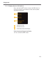
11Diagnosis.....................................................................................................................112
11.1 Trouble shooting for truck/bus.............................................................................113
11.2 Evaluation of the reception quality via Display.............................................116
11.3 Display device information:....................................................................................119
12 Dismantling and Disposal....................................................................................120
12.1Dismantling....................................................................................................................120
12.2Disposal............................................................................................................................122
13 Declaration of Conformity..................................................................................124
14Certifications.............................................................................................................124
14.1 Radio permit..................................................................................................................124
14.2 General Operating Permit........................................................................................124
14.3ADR.....................................................................................................................................124
15Index..............................................................................................................................125
5
General
1
General
1.1
Information on this Installation Manual
This Installation Manual is intended for qualified technicians
with technical know-how in vehicle electrics and tire fitting.
Knowledge of its contents enables the ContiPressureCheckTM
System (CPC System) to be installed on commercial vehicles.
Special instruction by qualified staff of Continental Reifen
Deutschland GmbH or their contractors is necessary for installing and activating the system.
This Installation Manual is a crucial aid to the successful
and safe installation of the system. It contains important instructions on installing and operating the system correctly
and safely. Observation of its contents helps avoid dangers,
increase the reliability and service life of the system and
maintain the system warranty, but is no substitute for the
above-mentioned special instruction.
Insure that online access to Installation Manual is available
in the garage conducting the install. It must be read and observed by everyone who is involved with
●● Installation,
●● Activation,
●● Operation
●● and/or Diagnosis
of the system.
Observe the instructions contained – in particular the safety
instructions.
6
General
1.2
Liability disclaimer
The manufacturer assumes no liability for damage and operational faults resulting from:
■■ Failure to observe this Installation Manual,
■■ Used for other than the intended purpose,
■■ Installation by unqualified or insufficiently qualified
personnel,
■■ Faulty installation,
■■ Use of other than original CPC spare parts and accessories,
■■ Technical changes and modifications,
■■ Failure to perform the prescribed visual inspections (see
Chapter „5.5 Final inspection of the bonding of the Tire
Sensor Container“) after installation of the Tire Sensor.
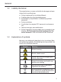
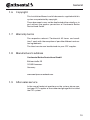
1.3
Explanation of symbols
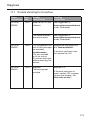
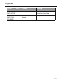
Warnings are additionally identified in this Installation Manual by warning symbols. The following warning symbols are
used in this Installation Manual:
Symbol
Meaning
General warning
Electric shock hazard
Hazard from health-endangering or
irritant substances
General instructions and useful suggestions on handling
Note on observing environmental
regulations for disposal
Electric/electronic components with
this symbol may not be disposed of in
the normal household waste.
7
General
1.4
Abbreviations
The following abbreviations are used in this Installation Manual:
Abbreviation Meaning
ADR
European agreement on international carriage of dangerous goods by road (Accord
européen relatif au transport international
des marchandises Dangereuses par Route)
ATL
Auto Trailer Learning
CAN
Data bus system for communication
between vehicle systems (Controller Area
Network)
CCU
Central Control Unit
CPC
ContiPressureCheckTM
DOT
Department of Transportation
DTC
Error message (Diagnostic Trouble Code)
GND
Ground
HHT
Hand-Held Tool
IGN
Ignition
Truck
Heavy Goods Vehicles
RSSI
Transmission power of the Tire Sensors
(Received Signal Strength Indicator)
Sensor ID
SO
StVZO
Sensor identification number
Surrounding Observer
German Road Traffic Licensing Act
SWE
Single Wheel Exchange
U-bat
Battery voltage
8
General
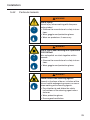
1.5
Warnings
The following warnings are used in this Installation Manual:
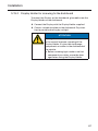
WARNING
A warning of this hazard level indicates a
hazardous situation.
If the hazardous situation is not avoided, it
can result in serious injuries.
►► Follow the instructions in this warning to
avoid serious injuries to persons.
CAUTION
A warning of this hazard level indicates a
potentially hazardous situation.
If the hazardous situation is not avoided, it
can result in injuries.
►► Follow the instructions in this warning to
avoid injuries to persons.
ATTENTION
A warning of this hazard level indicates
potential damage to equipment.
If the situation is not avoided, it can result in
equipment damage.
►► Follow the instructions in this warning to
avoid the equipment damage.
NOTE
►► A note draws attention to additional information of importance for further work or
which simplifies the work step described.
9
General
1.6
Copyright
This Installation Manual and all documents supplied with this
system are protected by copyright.
These documents may not be duplicated either wholly or in
part without the express permission of Continental Reifen
Deutschland GmbH.
1.7
Warranty terms
The respective relevant "Continental AG terms and conditions" apply with the exception of possible different contractual agreements.
The latest version can be obtained via your CPC supplier.
1.8
Manufacturer's address
Continental Reifen Deutschland GmbH
Büttnerstraße 25
30165 Hannover
Germany
www.contipressurecheck.com
1.9
After-sales service
In the case of technical questions on the system, please contact your CPC supplier or the authorized garage that installed
the CPC system.
10
Safety
2
Safety
2.1
General
This chapter contains important information on all aspects
of safety.
Apart from the general safety instructions given in this chapter, further safety instructions relevant to the operations covered are given in each of the chapters.
Hazards that could occur during a particular action are described before the instructions for each step.
WARNING
Hazard from failure to observe the safety
instructions!
Failure to observe the safety instructions and
handling instructions given in this Installation
Manual can create considerable hazards.
►► Observe the warnings and instructions
given here.
2.2
Prohibited modifications
All modifications and changes to the system are prohibited.
The manufacturer assumes no liability for any resulting damage.
11
Safety
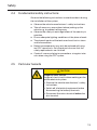
2.3
Intended use
This system is only intended for measurement of the tire
pressure and internal tire temperature and wireless transmission of the values to an external evaluation unit.
This system may only be used for its intended purpose within
the limits stipulated in the technical data.
Use for any other purpose is not considered as intended use.
Operation of the system in a faulty condition is prohibited.
WARNING
Hazard from use for other than the intended
purpose!
Any use other than and/or going beyond the
intended use of the CPC system can lead to
dangerous situations.
►► Use the CPC system only for its intended
purpose.
►► Comply with all instructions in this Installation Manual.
No claims of any kind will be accepted for damage resulting
from use for other than the intended purpose.
The risks associated with such improper use shall be borne
solely by the user.
2.3.1
Use of the Tire Sensors
The operator must ensure that tires in which Tire Sensors are
installed, are only operated in vehicles, in which monitoring
is ensured by the CPC system.
If continuous technical monitoring is not ensured, the operator must make sure that the condition of the Tire Sensor is checked regularly, at the latest after 20 000 km
(12 425 miles).
In the case of continued use of the tires on other vehicles
where monitoring is not ensured, the Tire Sensors must first
be removed from the tires.
12
Safety
2.4
Fundamental safety instructions
Observe the following instructions to avoid accidents during
the installation of the system:
■■ Observe the vehicle manufacturer's safety instructions.
■■ Take all necessary precautions before jacking up the
vehicle, e.g. to prevent rolling away.
■■ Observe the safety at work regulations of the country in
question.
■■ Ensure adequate lighting conditions at the place of work.
■■ The place of work and the tools used must be in a clean
and safe condition.
■■ Defective components may only be replaced with original CPC spare parts. Only these parts ensure that the
safety requirements are satisfied.
■■ Check all screw and plug-in connections at regular intervals when using the CPC system.
2.5
Particular hazards
CAUTION
Danger of short-circuit!
Danger of short-circuits when working on the
vehicle electrical system.
►► Observe the vehicle manufacturer's safety
instructions.
►► Switch off all electrical equipment before
disconnecting the battery terminals.
►► Disconnect the minus terminal before the
plus terminal.
13
Safety
■■ Do not kink cables, place cables under strain or lay cables over sharp edges.
■■ Do not install cables in the vicinity of rotating, moving or
hot parts.
■■ For cables, observe a bending radius of at least 15 mm
(0.6 inches); for corrugated tubes a bending radius of at
least 35 mm (1.4 inches).
■■ Ensure that plug connectors are clean and dry, and that
they are securely locked after connection.
■■ Secure the respective wiring harness after appropriately
max. 10 cm (4 inches) in front of and behind every plug
connection.
■■ Pay attention to effective sealing of the cable feedthroughs in the vehicle cab and in fuse and distribution
boxes.
■■ Use only suitable tools for stripping the cable insulation
and for crimping cable shoes.
■■ The installation of the CPC system on the vehicle (in particular when connecting to the power supply) must not
influence the function of other systems on the vehicle
(e.g. brake system or light system).
■■ Special feature in the case of a vehicle for hazardous
materials (ADR):
If the CPC system is installed in a vehicle for hazardous
materials (ADR) and if the CPC system remains switched
on although the vehicle ignition is switched off, it is
possible that sparks, other ignition sources or similar
could lead to a reaction with the hazardous material in
the event of a fault.
This can result in explosion and serious injuries.
–– For this reason, make sure that the power supply of
the CPC system is switched off when the vehicle is
parked (i.e., ignition is switched off).
14
Safety
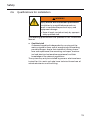
2.6
Qualifications for installation
WARNING
Injury hazard with insufficient qualification.
Installation by unqualified personnel can
result in considerable personal injury and
equipment damage.
►► Have all work carried out only by appropriately qualified staff.
The following qualifications are specified in this Installation
Manual:
■■ Qualified staff
is deemed capable of independently carrying out the
work assigned to them and of recognizing and avoiding
possible dangers due to their technical training, knowhow and experience (tire mounting and repair, mechanical and electrical automotive experience) and their
knowledge of the relevant regulations.
The system may only be installed by persons who have been
trained for this work and who have technical know-how of
vehicle electronics and tire fitting.
15
Safety
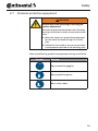
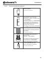
2.7
Personal protective equipment
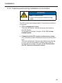
WARNING
Risk of injury due to wrong or missing protective equipment!
Personal protective equipment must be worn
during installation in order to minimize health
risks.
►► Wear the necessary protective equipment
for the work involved during the installation.
►► Follow the instructions for personal protective equipment posted in the working area.
Wear the following protective equipment during installation:
Symbol
Meaning
Wear protective goggles.
Wear protective gloves.
Wear safety shoes.
16
Technical data
3
Technical data
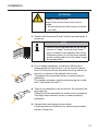
NOTE
►► All components to be installed on the
vehicle are designed for an operating temperature range of -40 °C to 85 °C (-40 °F to
185 °F). When other temperature ranges
are applicable, it is mentioned in the below
tables.
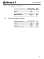
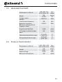
3.1
Tire Sensor
Dimensions (L x W x H)
Weight
Transmission frequency
Reception frequency
Typical service life* of the
permanently installed battery
approx.
Temperature measuring range
Pressure measuring range
(rel.)
38 x 28 x 22
1.5 x 1.1 x 0.87
26
0.92
433.92
mm
inches
grams
oz
MHz
125
6
kHz
years
or
600 000
372 820
-40 to 120
-40 to 248
0 to 12
0 to 173
km
miles
°C
°F
bar
psi
* Constantly high tire inside temperatures (caused for example by high
ambient temperature, low tire pressure, etc.) can lead to a decrease of the
battery service life.
17
Technical data
3.2
Central Control Unit (CCU)
Dimensions (L x W x H)
Weight
Supply voltage
Reception frequency
Minimum mating cycles
3.3
165 x 121 x 65
6.5 x 4.76 X 2.56
390
13.76
12/24
mm
inches
grams
oz
Volts
433.92
MHz
10
cycles
90 x 42 x 28
3.54 x 1.65 x 1.1
44
1.55
433.92
mm
inches
grams
oz
MHz
10
cycles
Additional Receiver (optional)
Dimensions (L x W x H)
Weight
Frequency
Minimum mating cycles
18
Technical data
3.4
Display
Dimensions (L x W x H)
Weight
Supply voltage
Minimum mating cycles:
- diagnosis plug
117 x 107 x 40
mm
4.60 x 4.21 x 1.57 inches
240
grams
8.47
oz
12/24
Volts
100
cycles
10
cycles
5
cycles
Operating temperature range
-40 to 85
-40 to 185
°C
°F
Readability of the LCD (screen)
without restrictions
-20 to 80
-4 to 167
°C
°F
- connecting plug
Minimum mating cycles
between Display and Display
Holder
19
Technical data
3.5
Hand-Held Tool (HHT)
Dimensions (L x W x H)
Weight
Charger supply
voltage
Transmission frequency
Reception frequency
Minimum mating cycles of
Diagnosis Cable:
Plug to Hand-Held Tool
All 3 plugs to vehicle components
Operating temperature range
Storage temperature range
3.6
160 x 90 x 38
6.3 x 3.54 x 1.5
750
26.46
mm
inches
grams
oz
220/110
Volts
125
kHz
433.92
MHz
1,000
cycles
100
cycles
-10 to 50
14 to 122
-40 to 85
-40 to 185
°C
°F
°C
°F
140 x 140 x 160
5.51 x 5.51 x 6.3
115
4.06
12/24
mm
inches
grams
oz
Volts
100
cycles
Pressure Check Indicator
Dimensions (L x W x H)
Weight
Supply voltage
Minimum mating cycles
20
Design and Function
4
Design and Function
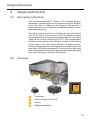
4.1
Description of function
The ContiPressureCheckTM System (CPC System) permits
continuous monitoring of the tire pressure and tire temperature. The status is shown on the Display. In the event of a
pressure drop in a tire, the driver immediately receives a corresponding warning.
The basic system consists of a Display, the Central Control
Unit (CCU), and the Tire Sensors. Each Tire Sensor fixed on
the inside of the tire, transmits the measured data via a radio
signal to the Central Control Unit (CCU). The analyzed data
are then transmitted via the CAN bus system to the Display
in the driver's cab. The system displays the required information during operation and monitors the temperature and
pressure of the tires continuously. In the case of a deviation
form the programmed value of the associated recommended
pressures, warning is shown on the Display.
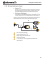
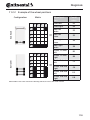
4.2
Overview
3
4
1
1
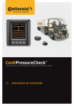
1 1
2
1
1
PRESSURE
(BAR)
9.0
7.5
1
1 2 2
9.0
7.5
7.5
7.5
9.0
9.0
9.0
9.0
9.0
9.0
3
Tire Sensor
Central Control Unit (CCU)
3 Display
4 Additional Receiver
21
Design and Function
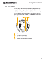
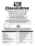
4.3
Tire Sensor
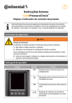
The Tire Sensor contains a pressure sensor, temperature sensor, acceleration sensor, evaluation circuit, radio transmitter
and lithium battery. The unit is molded in a plastic housing
and is introduced into a Tire Sensor Container.
The Tire Sensor Container is fixed to the tire inner-liner (for
more information, see chapter „5.4 Installation of the Tire
Sensor“).
3
1 4 2 3
1 Tire Sensor
2 Tire Sensor Container
3 Direction of tire rotation
4 Quarter and year of manufacture
22
Design and Function
NOTE
►► Under normal conditions, the service
life of the battery is approx. 6 years or
600 000 km (372 820 miles) (see also
Chapter „3.1 Tire Sensor“).
►► When the battery has expired, the warning
"NO SIGNAL" appears on the Display. As
this warning can also have other causes,
the status of the battery has to be checked
with the Hand-Held Tool at the Tire Sensor.
If the status "LOW battery" is displayed,
replace the Tire Sensor with a new sensor.
23
Design and Function
4.4
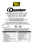
Central Control Unit (CCU)
The data recorded by the Tire Sensor are transmitted by radio to the Central Control Unit (CCU).
The radio communication is assured by an antenna integrated into the housing of the Central Control Unit which ensures
the fault-fre reception of the pressure and temperature signals from all the Tire Sensors.
The Central Control Unit (CCU) is designed for operation in a
12/24 Volt system.
The CCU is installed in a central position on the vehicle chassis so that fault-free radio communication with the Tire Sensors is assured. For most applications a special Bracket is recommended for installation to ensure good radio reception
(see Chapter „4.7 Bracket“).
The CCU for tractors, trailers and buses is available in two
versions:
●● Control unit with black plug:
without Pressure Check Indicator control
●● Control unit with gray plug:
with Pressure Check Indicator control
1
2
1 Housing
2
Connecting plug
The system can manage up to 24 Tire Sensors per control
unit. Faults occurring during operation are stored in the electronics for diagnostic purposes.
24
Design and Function
4.5
Additional Receiver (optional)
An Additional Receiver is necessary:
■■ If there is big distance (more than approx. 4 m/4,4 yds)
between the tires and the Central Control Unit (CCU).
■■ For monitoring trailer from the truck.
■■ For vehicles with more than 2 axles.
■■ For busses/coaches
1
2
3
1 Housing
2
Connecting plug
3
Impact Protection
The Additional Receiver must always be used with the Impact Protection.
NOTE
If the Impact Protection is not used,
►► the ContiPressureCheckTM system may not
be used for transporting hazardous materials (see Chapter „14.3 ADR“).
►► damage to the Additional Receiver is
possible.
►► the reception range of the Additional Receiver is reduced.
25
Design and Function
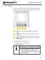
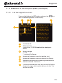
4.6
Display
A Display is installed in the driver's cab to show the tire information. This applies only to trucks and buses, not to trailers.
1
2
3
4
1
SET -button: Switch between vehicle view and settings
2
-button: Navigation between menu items and
warnings
3
OK -button: Confirmation of the selected menu item
4
-button: Switch between pressure and temperature display
On the rear side are the jacks for:
●● Power supply and communication
●● Diagnosis Cable
NOTE
►► The Display operates reliably in a temperature range from –20 °C to 80 °C (-4 °F
to 176 °F). At temperatures below –20 °C
(-4 °F) or above 80 °C (176 °F), the Display
may be impaired.
26
Design and Function
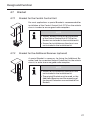
4.7
4.7.1
Bracket
Bracket for the Central Control Unit
For most applications a special Bracket is recommended for
installation of the Central Control Unit (CCU) on the vehicle
chassis in order to ensure good radio reception.
NOTE
►► Screws, washers and nuts for attachment
of the Central Control Unit (CCU) to the
Bracket are included in the installation kit.
►► Screws for installation on the chassis are
not included in the installation kit.
4.7.2
Bracket for the Additional Receiver (optional)
A special Bracket is necessary for fixing the Additional Receiver (and the associated Impact Protection) to the vehicle
chassis, in order to ensure good radio reception.
NOTE
►► Screws for installation on the chassis are
not included in the installation kit.
►► The original Bracket must be used, as the
Additional Receiver and the mounting of
the Impact Protection are matched to the
Bracket.
27
Design and Function
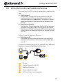
4.8
Wiring the truck/bus with Additional Receiver
For truck/bus, the CPC system is connected as explained below:
■■ Sub-Harness C:
Sub-Harness C comprises the connection of the Central Control Unit (CCU) to a distribution point in the
vicinity of the driver's workplace. This section is splash
water-proof so that it can be laid on the outside of the
vehicle.
■■ Sub-Harness A and B:
Sub-Harness A (with integrated fuse) and B are only conceived for enclosed spaces. A wiring set to the Display
(Sub-Harness B), and a wiring set with free cable ends for
connection to the supply voltage of the vehicle (Sub-Harness A).
Adapter cable for Additional Receiver:
■■ Sub-Harness D:
Connection of the Additional Receiver (optional) with
the Central Control Unit (CCU) takes place via Sub-Harness D.
The basic principle of wiring for the truck/bus with Additional
Receiver is shown in the following illustration:
B
C
2
1
4
A
D
3
5
1 Display
2
Central Control Unit (CCU)
3
4
Additional Receiver
5
ATO fuse 1 amp - exchangeable
Power supply (fuse box)
28
Design and Function
4.9
Pressure Check Indicator for trailer/semi-trailer
The trailer/semi-trailer can be operated with a separate Central Control Unit (CCU) independent of the towing vehicle. In
this case, a Pressure Check Indicator is installed on the outside of the trailer.
An example of the positioning of the Pressure Check Indicator is shown in the following figure:
NOTE
►► Above a speed of 110 kph (70 mph)
the visibility of the Pressure Check Indicator may be restricted.
29
Design and Function
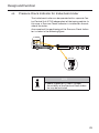
4.10 Wiring trailer/semi-trailer
■■ Harness F + G:
Harness F + G connects the Central Control Unit (CCU) to
the vehicle power supply (branch F) and the port for the
Hand-Held Tool/Pressure Check Indicator (branch G).
■■ Sub-Harness H (optional):
Connection of the Additional Receiver (optional) with the
Central Control Unit (CCU) takes place via Sub-Harness H.
The basic wiring principle for the trailer/semi-trailer with Additional Receiver is illustrated in the following diagram:
H
4
1
F+G
2
F+G
3
5
1
Pressure Check Indicator
2
Central Control Unit (CCU)
3
Power supply (distribution box)
4
Additional Receiver
5
1 amp ATO fuse - exchangeable (included in the
mounting kit)
30
Design and Function
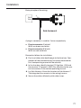
4.11 Hand-Held Tool, Diagnosis Cable
After installation, the system is initialized using the HandHeld Tool.
1
2
1
Charging cable port
2
USB and Diagnosis Cable port
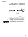
The Hand-Held Tool is connected to the Display or to the diagnostic plug of the trailer by means of the Diagnosis Cable.
A port is provided for this on the housing of the Display and
on the Hand-Held Tool. The diagnostic plug of the trailer is
the mating plug on the Pressure Check Indicator (see branch
G or Harness F+G).
NOTE
►► The Hand-Held Tool works safely in a temperature range from –10 °C to 50 °C (14 °F
to 122 °F). At temperatures below –10 °C
(14 °F) or above 50 °C (122 °F), the display
and transmitting power may be impaired.
►► Comprehensive operating instructions
for the Hand-Held Tool can be found at
www.contipressurecheck.com in the manual of the of the Hand-Held Tool.
31
Design and Function
4.12 Spare parts
An overview of available spare parts and the associated article numbers can be obtained from your CPC supplier or from
authorized CPC partner garage.
32
Installation
5
Installation
5.1
Scope of supply
NOTE
►► Check the entire delivery for completeness
and visual damage.
►► On delivery of the system, note any
damage due to improper packaging or
transport damage on the delivery note and
report it to your sales contact immediately.
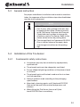
5.2
Disposal of the packaging materials
The packaging protects the system against transport damage. The packaging materials have been selected in line with
environmental and disposal aspects and are therefore recyclable.
Recycling the packaging saves raw materials and reduces
the production of waste. Packaging materials which are no
longer needed should be disposed of in accordance with the
local regulations.
33
Installation
5.3
General instruction
For proper and efficient installation and in order to avoid mistakes, the sequence of the installation steps described below
must be strictly observed.
NOTE
►► The CPC system must be installed no later
than 2 years after packing of the kits due
to ageing of the rubber (used particularly
in the Tire Sensor Container and Pressure
Check Indicator) and due to storage life
of battery used in Tire Sensor. Refer to the
sticker on the kit for the packing date.
►► The storage life of the Cyberbond CB 2250
Glue is shorter (observe the expiry date
and storage instructions on the packaging).
5.4
5.4.1
Installation of the Tire Sensor
Fundamental safety instructions:
■■ Installation may only be carried out by appropriately
qualified staff.
■■ The place of work must be adequately ventilated.
■■ Ensure adequate lighting conditions at the place of work
at all times.
■■ The place of work and the tools used must be in a clean
and safe condition.
■■ Store all products used according to the packaging
specifications.
■■ Keep tools, cleaning agents and Cyberbond CB 2250
Glue out of the reach of unauthorized persons and
children.
■■ When fitting the Tire Sensor, the use of Cyberbond CB 2250 Glue is mandatory.
34
Installation
5.4.2
Particular hazards
WARNING
Risk of injury!
Risk of injury when working with the pneumatic grinder!
►► Observe the manufacturer's safety instructions.
►► Wear goggles and protective gloves.
►► Wear ear protectors, if necessary.
WARNING
Risk of injury when working with Cyberbond
CB 2250 Glue!
Skin and eyelids are stuck together within
seconds.
►► Observe the manufacturer's safety instructions.
►► Wear goggles and protective gloves.
WARNING
Health hazard from cleansing agents!
Hazards in the form of burns, irritation of the
skin or health-endangering vapors can occur
when working with cleansing agents.
►► Pay attention to and follow the safety
instructions of the cleaning agent manufacturer.
►► Wear protective gloves.
►► Ensure good ventilation.
35
Installation
5.4.3
Tools and materials required
Protective gloves
(not included in the delivery)
1 x cleaning agent containing naptha
("Liquid Buffer" from Tip Top or
Continental, as well as "Pre-Buff Cleaner" from PREMA)
Continental article no.: 17080300000
Cleaning agent for pretreatment of
the tire inner-liner and the bonding
surface of the Tire Sensor.
("Liquid Buffer” from Tip Top and “Pre-Buff Cleaner” from PREMA are not included in the delivery)
1 x cleaning cloth
Cleaning cloth for cleaning the bonding surfaces.
(not included in the delivery)
1 x Tire Sensor Mounting Tool (including Insert)
article no.: 17340190000
Insert (Mounting Tool) (replacement
part) article no.: 17340220000
Tool for mounting the Tire Sensor.
1 x Glue Cyberbond CB 2250
Glue for affixing the Tire Sensor
CB
2250
(Part of every Tire Sensor Kit)
36
Installation
1 x Spatula
Tool for spreading the Glue on the
Tire Sensor.
(Part of every Tire Sensor Kit)
1 x Cleaning Scraper
Article No.: 17341300000
Scraper for pretreatment of the
tire inner-liner.
Additional tools for removing any ventilation ribs in the bonding area of the tire inner-liner (not included in the delivery):
Pneumatic grinder, slow-running
(max. 3600 rpm)
Contour disc, for low speeds
(65 mm, K 36)
e.g., TipTop article no.: 595 4357
5.4.4
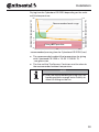
Information on Cyberbond CB 2250 Glue
ATTENTION
Damage to equipment!
Improper gluing of the Tire Sensor Container
in the tire can result in damage to the tire and
the Tire Sensor.
►► Safe gluing is not possible below 5 °C
(41 °F) (see red area).
►► To bond safely, pay attention to the recommended pressing time in relation to
temperature.
37
Installation
Drying time for Cyberbond CB 2250 depending on the ambient/tire temperature::
Ambient/tire temperature [°C]
Recommended work range
35
95
15
59
5
0
-5
41
32
23
-20
Gluing NOT possible
0
60
120
-4
Ambient/tire temperature [°F]
176
80
recommended pressing time for Cyberbond CB 2250 [sec]
■■ The recommended ambient/tire temperature for gluing
with Cyberbond CB 2250 is 15–35 °C (59-95 °F).
- see green area.
■■ The tire and the Tire Sensors Container must be close to
the recommended ambient temperature.
NOTE
►► After the recommended pressing time, the
bonding exhibits enough basic stability to
allow tire fitting on the rim.
38
Installation
5.4.5
Place of work
Before starting work, prepare the place of work so that all the
necessary tools and materials are within easy reach.
NOTE
►► The tires should have a temperature of
15 °C to 35 °C (59 °F to 95 °F) for bonding.
If the temperature is lower, the required
pressing time increases considerably during the gluing process (see diagram in the
Chapter „5.4.4 Information on Cyberbond
CB 2250 Glue“).
Safe gluing is not possible below a temperature of 5 °C (41 °F).
►► The place of work must be adequately
ventilated.
►► Position the tire so that the inner area of
the tire is easily accessible and well illuminated.
5.4.6
Permissible tire sizes
With proper installation, most standard tubeless truck tires
are fundamentally suitable for the installation of a Tire Sensor as long as the surface of the tire inner-liner is according
to the normal market.
The current table with permissible tire sizes can be found at
www.contipressurecheck.com.
NOTE
►► The Tire Sensor must not be used in tires
with inner tube.
39
Installation
5.4.7
Bonding position in the tire
The correct position of the bonding surface is:
■■ In the middle of the tire inner-liner.
■■ In the area of the DOT (Department of Transportation)
stamp.
Dimensions
of the bonding surface:
Dimensions
of the area to be cleaned:
approx. 6 x 6 cm
(approx. 2.5 x 2.5 inches)
approx. 7 x 7 cm
(approx. 3 x 3 inches)
40
Installation
NOTE
►► The Tire Sensor Container should preferably be bonded to a smooth surface.
►► Bonding on a honeycomb structure is possible. Minor unevenness can be compensated with Glue.
►► Remove ventilation ribs in the area of the
bonding surface before the bonding process. See Chapter „5.7 Removing ventilation ribs in the bonding area“.
►► The preparation is intended to that the
entire surface of the Tire Sensor Container
makes contact.
It is important to make sure that the Tire
Sensor Container edges are completely
bonded.
►► Avoid direct sunlight and drafts on the
bonding area.
41
Installation
5.4.8
Pretreatment of the bonding surface
ATTENTION
Risk of damage due to improper cleaning of
the bonding surfaces.
The Tire Sensor and the Tire Sensor Container can become loose and cause permanent
damage to the tire.
►► Brake cleaner or similar substances
may never be used for cleaning the glue
surfaces since this will impair the bonding
process.
►► Furthermore, the use of brake cleaner can
damage the tire.
NOTE
►► Due to tests performed by Continental
Reifen Deutschland GmbH, it is recommended to use "Liquid Buffer" from Tiptop,
Continental or "Pre-Buff Cleaner" from PREMA (see Chapter „5.4.3 Tools and materials
required“) to clean the bonding surfaces.
►► If any other products are used for cleaning, Continental Reifen Deutschland GmbH
cannot guarantee that adhesion is sufficient for the application.
►► Pay attention to the additional/updated
instructions on ContiPressureCheck installation and use at:
www.contipressurecheck.com
42
Installation
To clean the bonding surfaces, align the tire so that excess cleaning agent can flow out of the bonding area.
Shake the spray can (Liquid Buffer or Pre-Buff Cleaner).
Spray the complete dry bonding surface to be cleaned
with the cleaning agent from a distance of approx. 20 cm
(8 inches).
Use considerable force to scrape the bonding area to be
cleaned several times until the bonding area is dry. Take
care not to damage the tire inner-liner.
Repeat the cleaning process at least 2 times.
Afterwards, moisten the entire bonding area to be
cleaned with the cleaning agent and clean thoroughly
with the cleaning cloth. Wipe only in one direction and
always use clean areas of the cleaning cloth. Do not rub
any dirt into the bonding surface.
Repeat this process until the area to be cleaned clearly
differs from the uncleaned area.
Remove any residue from the tire caused by scraping an
cleaning.
Mark the outer edge of the bonding surface with chalk.
Be careful not to get chalk on the bonding surface.
Then, allow cleaning agent on the surface to evaporate
for approx. 3 minutes.
43
Installation
5.4.9
Inserting the Tire Sensor into the Tire Sensor Container
NOTE
►► Normally, the Tire Sensor is inserted in the
Tire Sensor Container before delivery.
Turn the sealing lip of the Tire Sensor Container inside
out.
Tip: Turning the sealing lip inside out on the short side
of the Tire Sensor Container is the easiest way (see black
arrow in the adjacent illustration).
Moisten the remaining surface in the Tire Sensor Container slightly with tire mounting lubricant.
Insert the Tire Sensor into the Tire Sensor Container. The
direction of rotation arrows on the Tire Sensor Container
continue onto the sensor (see illustration).
Push the sealing lip if the Tire Sensor Container back
up. The sealing lip of the Tire Sensor Container must lie
uniformly around the circumference on the top of the
sensor.
44
Installation
To ensure that the Tire Sensor sits better inside the Tire
Sensor Container, it is recommended to position the Tire
Sensor in the Tire Sensor Container by turning it correspondingly to the right/left.
The Tire Sensor is correctly inserted in the Tire Sensor Container when:
1. The arrows on the Tire Sensor Container continue exactly onto the Tire Sensor.
2. A slight elevation on the surface of the Tire Sensor is
visible and can be felt.
Faulty installation causes damage to the Tire Sensor during
operation. In this case, the CPC system indicates "CHECK
SENSOR / DEMOUNT TIRE“.
ATTENTION
Damage to equipment!
Improper insertion of the Tire Sensor into the
Tire Sensor Container causes damage to the
Tire Sensor and minimizes the CPC system
performance.
►► The Tire Sensor must be inserted correctly
according to the specifications.
►► The Tire Sensor may not be insert and operated transverse to the rolling direction
or upside down.
45
Installation
5.4.10 Tire Sensor activation
To activate the Tire Sensor, proceed as follows:
Select the "Activate Sensor" menu item in the Hand-Held
Tool and confirm with the Return button
.
Bring the Hand-Held Tool close to the Tire Sensor. The
Hand-Held Tool performs activation.
After activation, "Sensor successfully activated“ is displayed.
The Hand-Held Tool subsequently displays the current Tire
Sensor data:
–– Tire Sensor ID
–– Pressure
–– Temperature
–– State
The status must be "Activated".
If further messages are displayed, the Tire Sensor must be
replaced and activated again.
Possible messages are:
–– Sensor DEFECTIVE
–– LOW battery
–– Sensor is LOOSE
–– ACC: > 5 g/< -5 g
For an explanation on the messages of the Hand-Held Tool,
see "Hand-Held Tool user manual".
46
Installation
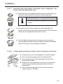
5.4.11 Inserting the Tire Sensor Container with integrated Tire
Sensor into the Mounting Tool
Place the Insert in the Mounting Tool so that the two arrows on
the Insert correspond with those on the Mounting Tool.
NOTE
►► Do not use the Mounting Tool without the
Insert.
Put gently the Tire Sensor Container with integrated Tire
Sensor into the Insert so that the two arrows on the Tire Sensor
Container are aligned with those on the Insert.
The Tire Sensor Container base surface must be in contact
with the Mounting Tool all round, otherwise check the position
of the Tire Sensor in the Tire Sensor Container.
5.4.12 Cleaning the bonding surface on the Tire Sensor Container
Shake the spray can (Liquid Buffer or Pre-Buff Cleaner).
Spray the cleaning agent onto the cleaning cloth.
Clean the bonding surface afterwards with the moistened cleaning cloth.
Perform this cleaning process at least 2x, but continue
until the area to be cleaned clearly differs to the uncleaned area.
Then, allow cleaning agent on the surface to evaporate for approx. 3 minutes.
47
Installation
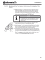
5.4.13 Bonding of the Tire Sensor Container with integrated Tire
Sensor
Before bonding, it is important to pay attention to the
recommendation with respect to the ambient temperature, the temperature of the tire and the Tire Sensor
Container, to ensure safe bonding (see Chapter „5.4.4
Information on Cyberbond CB 2250 Glue“)
NOTE
►► Cyberbond CB 2250 Glue contains a fluorescent agent which will enable verification of use.
Check the position of the Tire Sensor Container with
integrated sire sensor in the Mounting Tool.
Apply approx. 1 unit (see graduation marks on flask) of
the Glue to the bonding surface of the Tire Sensor Container and spread uniformly using the spatula.
Immediately after applying the Glue, press the Tire Sensor Container with integrated Tire Sensor perpendicularly onto the cleaned bonding surface using the Mounting
Tool. For proper positioning on the tire inner-liner, see
Chapter „5.4.7 Bonding position in the tire“.
48
Installation
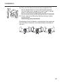
Press the Tire Sensor Container with integrated Tire
Sensor perpendicularly, firmly and steadily onto the
tire inner-liner with a weight of at least 5 kg (11 lbs) for
approx. 45 seconds using the press-in tool.
Do not move/swivel the Mounting Tool for 45 seconds!
Finally, release the Mounting Tool by moving it lightly
back and forth.
Avoid strong, jerky movement!
Positioning of the Tire Sensor is correct when the arrows on
the Tire Sensor Container are in the direction of motion of
the tires.
49
Installation
5.5
Final inspection of the bonding of the Tire Sensor Container
Inspect the bond visually. When bonded properly, the
Tire Sensor Container with integrated Tire Sensor is lying
completely on the inner-liner of the tire.
Carefully wipe any residual glue projecting over the
edge of the Tire Sensor Container away. Do not pull on
the Tire Sensor or the Tire Sensor Container during (at
least) the first 15 minutes.
The tires can be fitted immediately after bonding.
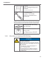
5.6
5.6.1
Instructions for tire fitting
Alignment of the tires
NOTE
►► In order to be able to better identify the
position of the Tire Sensor from the outside after fitting the tire, position the Tire
Sensor bonded into the tire in the area of
the DOT stamp close to the valve seat.
►► For twin tires:
To simplify the teach-in process of the Tire
Sensors, fit the twin tires so that the valves
and therefore the position of the Tire Sensors are at 180° offset to each other.
►► When fitting the tire using tools such as
tire levers, ensure that these do not damage the Tire Sensor.
50
Installation
5.6.2
Marking the wheels equipped with Tire Sensors
After fitting the tires, it is recommended to mark the tires that
contain a Tire Sensor.
For this purpose:
Attach the stickers supplied to the respective wheel
housings/mudguards so that they are clearly visible (one
sticker per wheel)
Replace the valve caps with the CPC valve caps supplied.
NOTE
►► The stickers are not suitable for attaching
to the rims or tires.
►► Before attaching the stickers, clean the
area with a suitable cleaning agent.
51
Installation
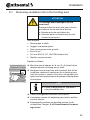
5.7
Removing ventilation ribs in the bonding area
ATTENTION
Tire damage due to damage to the tire
inner-liner!
Damage to the tire inner-liner can cause impairment of the service life of the tire.
►► Remove only the ventilation ribs.
►► Have the work carried out only by staff
trained in tire repairs.
Tool required:
●● Marking pen or chalk
●● Goggles, protective gloves
●● Slow-running pneumatic grinder
●● Brass brush
●● 65 mm /K36 (2-1/2”, SSG230) contour disc
●● Wet/dry vacuum cleaner
Proceed as follows:
Mark the area of approx. 8 x 8 cm (3 x 3 inches) to be
roughened with a marking pen or chalk.
Roughen the tire inner-liner with a contour disk. At the
same time, remove all ventilation ribs in bonding area
until the surface is smooth. Only press the contour disc
lightly and move continuously to prevent holding down
at one place.
NOTE
►► Create a rough patch of Type RMA 3
using the contour disc.
Clean the roughened area with a brass brush.
Completely remove all roughening dust with a wet/dry
vacuum cleaner.
Subsequently continue the bonding process as described from Chapter „5.4.8 Pretreatment of the bonding surface“.
52
Installation
5.8
Retreading
■■ Before retreading the tire, remove the Tire Sensor. The
Tire Sensor Container can remain in the tire.
■■ After retreading, insert the Tire Sensor into a new Tire
Sensor Container, see Chapter „5.4.9 Inserting the Tire
Sensor into the Tire Sensor Container“ and then insert
into the tire.
■■ Activate Tire Sensor as discribed in Chapter „5.4.10 Tire
Sensor activation“.
5.9
Continued use of the Tire Sensor after changing a tire
When the Tire Sensor is to be used again when a tire is replaced/or refitted, take the specified service life of the battery or operating time of the sensors according to Chapter
„3.1 Tire Sensor“ into consideration.
53
Installation
5.10 Use of balancing substances in commercial vehicle
tires
Numerous balancing substances from different manufacturers are available on the market for filling tubeless utility vehicle tires before the fitting process. These are predominantly pellets, pastes or liquids and mineral-based substances
whose effect (in operation) is intended to eliminate the need
for conventional balancing of the wheels.
We neither recommend nor expressly forbid the use of these
substances in our tires: Continental Reifen Deutschland
GmbH can give no generally applicable comments on the
quality and field of application of these substances as they
can vary from manufacturer to manufacturer.
The user of such substances should ask the respective manufacturer/dealer about their properties in detail before using
them in tires. Ultimately the user has to decide on the method of balancing of commercial vehicles tires and on the use
of balancing substances with respect to the specific operating conditions of the tire.
The use of balancing substances in commercial vehicle tires
from the Continental Group does not automatically lead to
the voiding of the liability for technical defects. However, tire damage and damage to the ContiPressureCheckTM
components caused or enhanced by the use of balancing
substances is not covered under the ContiPressureCheckTM
warranty.
Balancing substances should be completely removed from
the removed tire before the tire is sent to the incoming inspection for retreading or repair. We should also point out
that we will completely remove any balancing substances
in tires sent to us with complaints. Balancing substances removed from the tires will not be returned nor will any refund
be given.
54
Installation
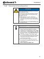
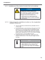
5.11 Installation of the Central Control Unit on truck/bus
ATTENTION
Damage to the Centrat Control Unit!
When selecting a suitable installation location, observe the following points to avoid
damage to the Central Control Unit:
►► Avoid proximity to high temperature
sources (e.g., exhaust system), rotating or
moving parts.
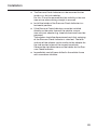
5.11.1 Determining the installation location on the longitudinal
member of the truck
■■ The unit should be installed mid-way between the first
and last axle.
■■ Install the Bracket so that the Central Control Unit (CCU)
extends as far as possible under the longitudinal member in order to ensure good radio contact with the Tire
Sensors (maintain safety distances e.g. to the road). For
good wireless connection, the CCU must not be shielded
by metal barriers in the immediate vicinity.
■■ Choose the distance to the driver's cabin so that the
length of Sub-Harness C (9 m/ 9.8 yds) ranges into the
fuse box.
NOTE
►► The protruding length of the Bracket (gap:
Lower edge of chassis frame to Central
Control Unit) must not exceed 12 cm
(4.72 inches) (see Chapter „5.11.2 Mounting“).
55
Installation
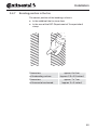
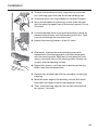
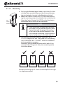
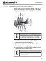
5.11.2 Mounting
■■ For fixing the Bracket to the I-beam, use at least 2 of the
suitable holes provided. Measure the distance between
the existing holes, transfer to the Bracket and install.
max.
12 cm
■■ Mount the Central Control Unit (CCU) on the Bracket using the mounting material included in the installation kit.
Align the Central Control Unit (CCU) so that the plug-in
connection points to the rear of the vehicle.
(4.72 inches)
NOTE
►► If the installation situation does not otherwise allow, it is possible to align the Central
Control Unit with the plug-in connection
to the side of the vehicle. However, in this
case, damage to the plug / plug-in connection by flying stones cannot be ruled out.
■■ Use suitable installation materials (bolts min. M 10
(7/16”), strength class min. 8.8 (grade 5.2)), self-locking
nuts and washers dia. ≥ 24 mm (1 inch) for attachment
to the longitudinal members.
Preferably, fixing should take place with 4 bolts. If this
is not possible, fixing must take place according to the
illustration below.
CCU
CCU
CCU
CCU
Examples for fixing with 2 screws (the example on the right
is a negative example).
56
Installation
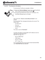
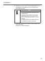
5.11.3 Installation location on the bus
In the case of the bus, an Additional Receiver is always required.
Install the Central Control Unit (CCU), preferably on the chassis. If this is not possible, both components can be installed
in the trunk. Both components may not be shielded by metal
walls to the Tire Sensor.
■■ Install the Central Control Unit (CCU) in the trunk as
close as possible to the front axle.
■■ Attach the Additional Receiver as near to the rear axle/s
as possible.
57
Installation
5.12 Installation of an Additional Receiver (optional)
ATTENTION
Damage to the Additional Receiver!
When selecting a suitable installation location, observe the following points to avoid
damage to the Additional Receiver:
►► Avoid proximity to high temperature
sources (e.g., exhaust system), rotating or
moving parts.
In the case of vehicles with a large wheelbase and vehicles
with more that 2 axles, an Additional Receiver is necessary to
improve the radio contact.
NOTE
►► If an Additional Receiver is installed, the
Central Control Unit (CCU) must be attached in the vicinity of the front axle and
the Additional Receiver at the rear of the
vehicle.
58
Installation
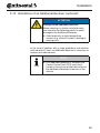
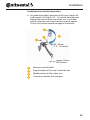
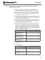
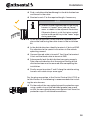
5.12.1 Requirements for optimum reception
The reception area of the Additional Receiver is similar to that
of a sphere, whereby the reception quality decreases as the
distance to the Tire Sensors increases. Reception is restricted
in the area behind the Bracket (see illustration below).
The optimum position of the Additional Receiver is
■■ in the middle of the vehicle’s rear end
and
■■ with the smallest possible gap to the floor
(observing safety gaps, e.g. to the road).
Ideally, this allows a direct line of sight between the Additional Receiver and the side walls of all tires to be monitored.
NOTE
►► If the Additional Receiver is attached offset
to the side, so that the front face points
to the tread of some of the tires, there is
a risk that reception of the sensor signals
from these tires could be impaired.
59
Installation
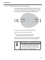
5.12.2 Positioning the Additional Receiver
The preferred installation location for the Additional Receiver is the rear of the vehicle, particularly when the trailer also
has to be monitored.
■■ The holes for fitting the Bracket of the Additional Receiver are drilled according to the hole pattern of common
tractor units in Europe. If the hole pattern of the Bracket
is not available on the chassis, then use the hole pattern
available on the chassis and drill the holes accordingly
into the Bracket.
NOTE
►► The Additional Receiver should be mounted so that the there is no metal directly
behind it.
This could impair the reception quality.
■■ The Bracket should be mounted so that the open side
of the U profile points to the trailer and the Additional
Receiver has the smallest possible gap to the ground
(observing safety gaps, e.g. to the road).
Due to the quasi sphere-shaped reception characteristics, not only the trailer tires are monitored in this case,
but also the rear axles of the towing vehicle.
■■ Attach the Bracket with suitable fixing material (at least
manufacturing class 8.8 (grade 5.2) screws as well as
self-locking nuts and washers). Attach the Additional
Receiver with the plug connector facing upwards.
60
Installation
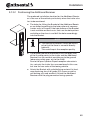
5.12.3 Mounting the Impact Protection on the Additional Receiver
After connecting Sub-Harness D with the Additional Receiver (see Chapter „5.13 Installation of Sub-Harness D from the
Central Control Unit to the Additional Receiver“), the Impact
Protection must be mounted.
Place the Impact Protection over the Additional Receiver
and anchor it in the Bracket.
Insert the 4 snap hooks into the corresponding openings
of the Bracket and press the Impact Protection against
the Bracket so that all 4 snap hooks are engaged.
Secure the Impact Protection with two cable straps (not
included in the delivery) as illustrated.
NOTE
If the Impact Protection is not used,
►► the ContiPressureCheckTM-System may not
be used for hazardous goods transport
(see Chapter „14.3 ADR“).
►► damage to the Additional Receiver is
possible.
►► the reception range of the Additional Receiver is reduced.
61
Installation
5.13 Installation of Sub-Harness D from the Central Control
Unit to the Additional Receiver
ATTENTION
Damage to the wiring harness!
When laying the wiring harness, observe
the following points to avoid damage to the
harness:
►► Avoid proximity to high temperature
sources (e.g., exhaust system), rotating
or moving parts.
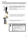
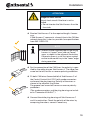
Sub-Harness D of the Additional Receiver is supplied with
water-proof plugs. To install Sub-Harness D, perform the following steps:
Connect Central Control Unit (CCU) first.
Lay the cable along the existing wiring harness of the
vehicle and fasten loosely with cable straps.
Insert the plug of the Additional Receiver into the Bracket from the back and plug-in to the Additional Receiver.
62
Installation
Push the corrugated pipe onto the plug until it stops
and then fix it to the protruding metal latch with a cable
strap. If properly mounted, the 3 wires must not be visible (see adjacent examples).
Secure the cable along the vehicle wiring harness sufficiently with cable straps.
On the Bracket of the Central Control Unit (CCU), secure
the T-cable of Sub-Harness D with a cable strap.
Lay the excess cable in loops and secure with at least
two cable straps.
For the plug connection on the Central Control Unit (CCU)
and to Sub-Harness C, the following is recommended:
Fix the ends of the corrugated pipe with the protection
caps using a cable strap at the indicated groove (see
arrow) so that the corrugated pipe cannot detach itself
from the protection caps in unfavorable conditions.
63
Installation
5.14 Installation of Sub-Harness C from the Central Control
Unit to the fuse box
ATTENTION
Damage to the wiring harness!
When laying the wiring harness, observe
the following points to avoid damage to the
harness:
►► Avoid proximity to high temperature
sources (e.g., exhaust system), rotating
or moving parts.
Connect the plug end of Sub-Harness C to the Central
Control Unit (CCU) or to the mating plug of Sub-Harness
D (if used).
From there, lay the cable along the existing wiring harness of the vehicle to the driver's cab and fasten loosely
with cable straps.
Lay the wiring harness to the fuse box of the vehicle (see
also vehicle operating manual).
Finally secure the cable along the vehicle wiring harness
with cable straps once again.
For the plug connection at the Central Control Unit (CCU) or
to Sub-Harness D, the following is recommended:
Fix the end of the corrugated pipe with protection cap
using a cable strap at the indicated groove (see arrow)
so that the corrugated pipe cannot detach itself from the
protection cap in unfavorable conditions.
64
Installation
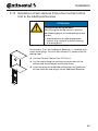
5.15 Mounting the Display (optional)
WARNING
Risk of injury!
The risk of injury cannot be ruled out if the
installation instructions are not followed.
►► Mount the Display offset to the side of the
driver and the front passenger(s).
►► Do not mount the Display in the impact
zone of the body or the head and not in the
airbag area (driver & front passenger).
NOTE
The vehicle driver must have a sufficient
field of view under all operating and weather conditions.
►► Mount the Display so that the field of view
of the driver is not restricted.
65
Installation
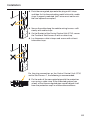
5.15.1 Display Holder with suction cup for attaching to the windshield
To attach the Display onto the windscreen, use the Display
Holder with the suction cup.
Connect the Display with the Display Holder supplied.
Make sure that the Display is completely snapped and
locked into the Display Holder.
Choose a suitable location on the windscreen. Pay attention to possible dazzling by sunlight.
NOTE
National regulations!
►► If national regulations stipulate that devices may no be attached to the windscreen,
mount the Display with the Display Holder
according to Chapter „5.15.2 Display Holder for screwing to the dashboard“
66
Installation
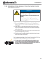
5.15.2 Display Holder for screwing to the dashboard
To mount the Display on the dashboard, glue and screw the
Display Holder on the dashboard.
Connect the Display with the Display Holder supplied.
Chose a suitable location on the dashboard. Pay attention to possible dazzling by sunlight.
ATTENTION
Damage!
In the case of improper screwing of the
Display Holder, it is possible to damage
components or cables in the dashboard of
the vehicle:
►► Before screwing tight, maker sure that
components or cables cannot be damaged when fixing the Display Holder.
67
Installation
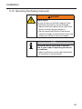
Remove the Display from the Dispaly Holder.
Pull of the protective foil of the contact surfaces on
the Dispaly Holder and glue the Display Holder to the
desired location.
Also screw the Display Holder into the dashboard with
the 2 screws supplied.
Connect the Display with the Display Holder supplied.
Make sure that the Display is completely snapped and
locked into the Dispaly Holder.
NOTE
It is recommended to fix the Display Holder
by gluing and screwing!
►► The glue foil compensates unevenness between the Dispaly Holder and installation
location and ensures a tighter fit.
►► The screws secures the Display Holder
against vibration during operation and
therefore against unintentional loosening.
NOTE
Dismantling the Display Holder!
►► After dismantling the Display Holder, two
holes remain in the dashboard. In addition,
residual glue could remain on the dashboard.
68
Installation
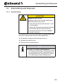
5.16 Finalizing work during installation on truck/bus
ATTENTION
Danger of short-circuit!
►► Switch off the ignition before starting
work.
The CPC system can be operated in 2 ways when installed in
a truck/bus:
■■ CPC as independent system
The status of the tires and the warnings are shown on
the CPC Display.
Installation instructions: Chapter „5.16.1 CPC as independent system“.
■■ Connection of the CPC system to a third-party system
(e.g., telematic system, dashboard display or vehicle CAN
bus)
The status of the tires, the warnings ad the error messages must then be displayed on another display device.
Installation instructions: Chapter „5.16.2 Connection of
the CPC system to a third-party system“.
69
Installation
5.16.1 CPC as independent system
Basic principle of the wiring:
TR 15
TR 31
2
1
A plug-in connector is used for 2 wires respectively:
■■ Plug-in connector 1 (white):
Wires are brown and white
■■ Plug-in connector 2 (black):
Wires are red and black
Proceed as follows for installation:
Identify a suitable cable feedthrough behind the dashboard from the Display to the fuse box; components of
the dashboard may have to be loosened for this (see
operating manual of the vehicle).
Lay Sub-Harness B behind the dashboard. Lay the open
end from the dashboard to the fuse box.
Secure the cable sufficiently with cable straps.
Secure loosened parts of the dashboard again.
In the fuse box, identify terminal 15 (ignition - IGN) and
the terminal 31 (ground - GND). Pay attention to the special instructions in the vehicle operating manual.
Lay Sub-Harness A from the fuse box to cables B and C.
The integrated fuse remains in the wiring harness.
70
Installation
ATTENTION
Danger of short-circuit!
Risk of short-circuit if the fuse is not installed.
►► Do not shorten the Sub-Harness A on the
fuse side.
Shorten Sub-Harnesses B and C to the required length, if
necessary.
NOTE
►► Shorten the corrugated pipe on the wiring
harness in "upper" areas and not "lower"
areas as shown in the adjacent illustration.
Otherwise there is a risk that wires routed
on the inside could fray in the "lower" edge
during operation.
First fit spade connectors to the two CAN terminals
(brown/white) of Sub-Harness C of the Central Control
Unit (CCU) and install the connector housing. Polarity of
the wires as shown in the adjacent illustration.
The groove (see arrow left) serves as reverse polarity
protection.
(The spade connectors and the plug housing are included in "Connector Kit A+B+C".)
Then fit flat connectors to Sub-Harness B and mount the
plug housing.
The polarity from connector to socket must correspond.
The ridge (see arrow left) serves as reverse polarity
protection.
Connect both white plugs to each other
Check the polarity of the wires by comparing the colors,
correct if necessary.
71
Installation
In the following step, fit flat connectors to the red and
black wires of Sub-Harnesses B and C and mount the
black plug housings.
The polarity of the plugs is already prescribed by
Sub-Harness A.
(The flat plugs and the plug housings are included in
"Connector Kit A+B+C".)
Subsequently connect the black plugs of Sub-Harnesses
A, B, and C with each other.
Connect Sub-Harness A to terminal 15 (ignition - red)
and terminal 31 (ground - black).
Subsequently lock the fuse box again properly. Take into
consideration that the original sealing of the fuse box
must be ensured after completing the installation.
Connect the plug of the Sub-Harness B to the Display.
Secure loosened parts of the dashboard again.
NOTE
►► If the CPC is used as independent system,
please select the “CPC+J1939” setting for
the CAN bus format while using the HandHeld Tool functions “Installation - New
Installation” or “Modification - Modify
Installation - Modify Parameters“.
72
Installation
5.16.2 Connection of the CPC system to a third-party system
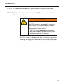
5.16.2.1 Safety instructions when using the CPC system connected to
third-party system
WARNING
Risk of injury!
If the CPC system is connected to a safety-related CAN bus, the safety-related CAN messages might be influenced. This can result in
accidents and serious injuries.
►► The CPC system may not be connected
to a safety-related CAN bus without prior
written permission Continental.
The CPC system is designed so that all necessary warnings
and error messages are shown to the driver on the Display or
via the Pressure Check Indicator as quickly as possible.
73
Installation
If the CPC system is used in conjunction with a third-party
system and the Display or the Pressure Check Indicator is not
used, then:
■■ The fleet manger must ensure that the driver is notified
appropriately and as quickly as possible when warnings
or error messages occur.
NOTE
►► In the case of high-level warnings (see
table on following page) and error messages, the driver must be notified appropriately when the warning / error message
occurs.
►► In the case of low-level warnings (see table
on following page), the driver should be
notified appropriately when the warning
occurs.
74
Installation
The following table provides an overview on possible warnings.
For detailed information and handling instructions on warnings, see the corresponding chapter in the User Manual of
the CPC system.
Priority: Level
High
Symbol
72
Warning
message
FAST PRESS. LOSS
High
2*)
77
1*), 2*)
VERY LOW
PRESSURE
CHECK SENSOR
2*)
86
LOW PRESSURE
Low
1*)
116
TEMPERATURE
NO SIGNAL
SENSOR DEFECT
Reason
Continuous, fast pressure loss.
Tire damage and tire destruction will occur.
The tire pressure falls below
the recommended alarm
threshold value. Tire damage
or even tire destruction is
possible.
The Tire Sensor is no longer
properly affixed.
The tire pressure falls below
the recommended warning
threshold value. Tire damage
or even tire destruction is
possible.
The measured temperature
in the tire exceeds 115 °C
(239 °F). The Tire Sensor no
longer functions at 120 °C
(248 °F).
Due to insufficient signal
strength, it is not possible to
display a sensor protocol.
Tire Sensor is defective
Low
1*)Tire pressure values shown above are for example proposes only. Recommend tire pressure is set
according the tire manufactures’ guidance by an authorized garage.
2*)High level warnings are indicated by flashing symbols changing between positive and negative
mode.
NOTE
►► For details on possible error messages, see
chapter „11.1 Trouble shooting for truck/
bus“.
75
Installation
5.16.2.2 Connecting the CPC system to a third-party system
The CPC system has 2 CAN termination resistors. One in the
Central Control Unit (CCU) and an other at the open end of
Sub-Harness L (marked by the red shrink tube).
Connection of the CPC system to a third-party system requires prior checking and adherence to the following points:
■■ With the help of the documentation on the third-party
system, check whether and which of the two CAN termination resistors of the CPC system are required.
■■ Observe the specifications of SAE J1939-15, particularly
with respect to the permissible lengths of the CAN lines
and the branch lines.
NOTE
►► If the Display is also to be used, take into
account that one CAN termination resistor
is also located in the Display. This cannot
be deactivated.
Basic principle of the wiring
120R
CAN_H
CAN_L
Sub-harness L
Sub-harness B
Sub-harness C
Sub-harness A
Sub-harness D
76
Installation
Basic principle of the wiring
2
TR 15
TR 31
1
Sub-harness L
A plug-in connector is used for 2 wires respectively:
■■ Plug-in connector 1 (white):
Wires are brown and white
■■ Plug-in connector 2 (black):
Wires are red and black
Proceed as follows for installation:
Find a suitable cable feedthrough to the fuse box. Components of the dashboard may have to be loosened for
this (see operating manual of the vehicle).
In the fuse box, identify terminal 15 (ignition - IGN) and
the terminal 31 (ground - GND). Pay attention to the special instructions in the vehicle operating manual.
Lay Sub-Harness A from the fuse box to Sub-Harness C.
The integrated fuse remains in the wiring harness.
Secure the cable sufficiently with cable straps.
77
Installation
ATTENTION
Danger of short-circuit!
Risk of short-circuit if the fuse is not installed.
►► Do not shorten the Sub-Harness A on the
fuse side.
Shorten Sub-Harness C to the required length, if necessary.
If Sub-Harness C represents a branch line in the CAN bus
network, keep this a short as possible (see specifications
from SAE J1939-15).
NOTE
►► Shorten the corrugated pipe on the wiring
harness in "upper" areas and not "lower"
areas as shown in the adjacent illustration.
Otherwise there is a risk that wires routed
on the inside could fray in the "lower" edge
during operation.
For the connection of the CAN lines, the polarity is specified by the white plug on Sub-Harness L. The ridge (see
arrow on the left) serves as reverse polarity protection.
Fit both CAN wires (brown/white) of Sub-Harness C of
the Central Control Unit (CCU) with spade connectors
and mount the plug housing. Polarity of the wires as
shown in the adjacent illustration.
The groove (see arrow left) serves as reverse polarity
protection.
(The spade connectors and the plug housing are included in "Connector Kit A+B+C".)
Connect the white plug housings of Sub-Harnesses C
and L to each other. Check the polarity of the wires by
comparing the colors, correct if necessary.
78
Installation
NOTE
Sub-Harness C must be laid so hat the open
end (with the white plug) is located inside the
driver's cabin or inside a protected room.
►► The open end of Sub-Harness C does not
meet the ADR requirements.
►► The open end of Sub-Harness C is not suitable for outside installation (no IP69k).
Lay the branch with the open end of Sub-Harness L to
the third-party system.
For this, determine a suitable cable feed through out
of the fuse box to the access point of the third-party
system, components of the dashboard may have to be
loosened for this (see operating manual of the vehicle).
NOTE
►► During installation, ensure that the diagnostics plug of Sub-Harness L is positioned
for easy access.
Lay Sub-Harness L and secure sufficiently with cable
straps.
79
Installation
Fix the branch with the diagnostics plug appropriately.
NOTE
Sub-Harness L may only be used inside the
driver's cabin or inside a protected room.
►► Sub-Harness L does not meet ADR requirements.
►► Sub-Harness L is not suitable for outside
installation (no IP69k)
For final connection work, pay attention to the following:
Option
Action
Termination resistor of
Sub-Harness L not required.
Short the cable accordingly.
Termination resistor of
Sub-Harness L is required.
Do not shorten cable.
Termination resistor in the
Central Control Unit (CCU)
not required.
Install Sub-Harness E
(see chapter „5.16.2.3
Deactivating the CAN
termination resistor in
the Central Control Unit
(optional)“.
Lay the excess cable in
loops and secure with at
least 2 cable straps.
Connect the open ends of Sub-Harness L to the third-party system.
Establish the connections according to the manufacturer
documentation of the third-party system. Pay attention
to the correct polarity.
80
Installation
Connect the black plug housing of Sub-Harnesses A and
C to each other.
Connect Sub-Harness A to terminal 15 (ignition - red)
and to terminal 31 (ground cable - black).
Subsequently lock the fuse box again properly. Take into
consideration that the original sealing of the fuse box
must be ensured after completing the installation.
Secure loosened parts of the dashboard again.
NOTE
►► If the CPC system is connected to a
third-party system, consult the supplier of
the third-party system to clarify which CAN
bus format is required for this application:
––CPC+J1939:
PGNs 65268, 65280, 65281, 65282,
65284, 64578
––J1939 Standard: PGNs 65268, 64578
►► Settings are made via the Hand-Held Tool
within "Installation - New Installation" or
"Modification - Modify Installation - Modify
Parameters".
81
Installation
5.16.2.3 Deactivating the CAN termination resistor in the Central Control
Unit (optional)
NOTE
►► If the CAN termination resistor of the
Central Control Unit (CCU) is deactivated
by Sub-Harness E, pay attention to the
specifications of SAE J1939-15 or the
permissible lengths of the CAN line and
the branch lines.
Sub-Harness E must be used when the CAN termination resistor in the Central Control Unit (CCU) must be deactivated (see chapter „5.16.2.2 Connecting the CPC system to a
third-party system“).
For this, Sub-Harness E must be mounted between Sub-Harness C and the Central Control Unit (CCU) (see illustration
below).
Basic principle of the wiring when connecting Sub-Harness E.
Sub-harness E
Sub-harness C
82
Installation
If an Additional Receiver is used, Sub-Harness E can be
mounted between Sub-Harness D and the Central Control
Unit (CCU) (see illustration below) or Sub-Harnesses C and D.
Basic principle of the wiring when Sub-Harness E and the Additional Receiver are used.
Sub-harness E
Sub-harness C
Sub-harness D
(optional)
For both plug connections of Sub-Harness E, the following is
recommended after successful wire harness installation:
Fix both ends of the corrugated pipe with protection
caps using a cable strap at the indicated groove (see
arrow) so that the corrugated pipe cannot detach itself
from the protection caps in unfavorable conditions.
83
Installation
5.17 Installation of the Central Control Unit (CCU) and an
optional Additional Receiver on the trailer/semi-trailer
NOTE
►► In the case of complex trailers/semi-trailers (e.g., more than 3 axles), it is recommended to use an Additional Receiver. In
this case the Central Control Unit (CCU)
should be positioned as close as possible
to the first/last axle, and the Additional Receiver as close as possible to the last/first
axle (determine the position of the CCU
according to the access to the distribution
box and the installation position of the
Pressure Check Indicator).
ATTENTION
Damage to the Central Control Unit and to
the Additional Receiver!
These components can be damaged by
their proximity to high temperatures, rotating or moving parts.
►► When selecting the installation location,
avoid proximity to high temperature
sources and to rotating or moving parts.
Install the Bracket of the CCU at a suitable location in the
area mid-way between the axles.
84
Installation
Allow the Central Control Unit (CCU) to extend as far as
possible downwards in order to ensure a good wireless
connection to the Tire Sensors (observing safety gaps,
e.g. to the road). For good wireless connection, the CCU
must not be shielded by metal barriers in the immediate
vicinity.
For fixing the Bracket and aligning the Central Control
Unit, see chapter „5.11.2 Mounting“.
Lay branch G of Harness F+G temporarily on the vehicle
(detailed description in chapter „5.19 Installation of the
Harness F+G from the Central Control Unit to the Pressure Check Indicator, diagnostic port and distribution
box“) in order to check whether the length of branch G
is sufficient to connect the CCU to the Pressure Check
Indicator. The position of the Pressure Check Indicator
may have to be adjusted accordingly.
85
Installation
5.18 Installation and adjustment of the Pressure Check
Indicator.
5.18.1 Installation position of the Pressure Check Indicator
The installation of the Pressure Check Indicator is preferably between the first and second side-marker lamp on the
left-hand side of the vehicle. With long trailers, the Pressure
Check Indicator can also be installed further back due to the
wiring harness length available. Install the Pressure Check Indicator like a side-marker lamp on the vehicle.
NOTE
►► The Pressure Check Indicator must not
obstruct the visibility of any side-marker
lamp.
►► Keep a free beam angle of at least 45° in
front of and behind side-marker lamps.
►► Side-marker lamps must not be removed
or repositioned.
►► The Pressure Check Indicator is not a
substitute for a side-marker lamp or other
lights. It does not belong to the vehicle
lighting in accordance with US regulation
and with regulation UN ECE R 48. It may
only be installed on the vehicle in conjunction with the ContiPressureCheckTM
system.
ATTENTION
Damage to the Pressure Check Indicator!
Risk of damage if the Pressure Check Indicator is installed in the marked area for crane
loading.
►► Do not use the marked area if the vehicle
is loaded by crane.
86
Installation
ATTENTION
Damage to the Pressure Check Indicator!
If the Pressure Check Indicator is installed
on vehicle with side gate there is a risk to
damage the Pressure Check Indicator by the
falling side gate. The rubber arm of the Pressure Check Indicator is designed to be bent
by the falling side gate. The movement of
the rubber arm along the side gate should
not be obstructed by unevenness and projecting parts on the side gate.
►► Position the holder of the Pressure Check
Indicator accordingly and check the bend
of the rubber arm.
87
Installation
Conditions of the installation position
■■ For good adjustability, position the Pressure Check Indicator approx. 30-40 mm (1.2 - 1.6 inches) from the outer
edge of the vehicle. When the rubber arm is in middle
position, the Pressure Check Indicator extends approx.
20 mm (0.8 inches) beyond the edge of the vehicle.
1
4
2
3
30 - 40 mm
(1.2 - 1.6 inches)
approx. 20 mm
(0.8 inches)
1
Maximum vehicle width
2
Edge of holder of Pressure Check Indicator
3
4
Middle position of the rubber arm
Caution on vehicles with side gate
88
Installation
■■ The Pressure Check Indicator can be mounted further
inside, e. g., for tank vehicles.
For this, it must be ensured that the visibility in the rear
view mirror when driving straight is ensured.
■■ Install the holder of the Pressure Check Indicator in a
horizontal position.
■■ If the Pressure Check Indicator cannot be installed
directly on the outer frame of the vehicle, a corrosion-resistant adapter (e.g. sheet of aluminum) must be
prepared.
The adapter should be dimensioned such that swinging
of the Pressure Check Indicator is ruled out. The form
and size of the adapter can be similar to the adapter for
the side-marker lamps of the respective vehicle.
Observe the slot dimensions on the holder for the Pressure Check Indicator.
■■ Immediately coat all bores drilled in the vehicle frame
with a corrosion inhibitor.
89
Installation
5.18.2 Installation of the Pressure Check Indicator.
5 mm
(0.2 inches)
70 mm
(2.76 inches)
Ideally, install the Pressure Check Indicator using the A
marked slots. Mark the place holder for holes in the middle
of the slots in order to be able to readjust the Pressure Check
Indicator during installation.
NOTE
►► Use one screw on each side of the holder.
►► Two screws at position B is not permitted.
Drill 2 holes with Ø 5.5 mm (0.22 inches) at position A in
the frame or adapter with a gap of 70 mm (2.76 inches).
Protect the drill holes against corrosion.
Fix the Pressure Check Indicator with Ø 5 mm (0.2 inches) screws.
Screw types: self-locking with spring loading.
Use washers with 15 mm (0.6 inches) diameter to fix the
holder of the Pressure Check Indicator.
NOTE
►► Screws and washers are not part of the
installation kit.
90
Installation
5.18.3 Adjustment of the Pressure Check Indicator.
60 cm
23.6 inches
5°
The Pressure Check Indicator has a beam angle of 5°. In this
range, it has the optimum luminosity. Outside this beam
angle the luminosity decreases very rapidly. The diameter of the beam at a distance of 7 m (7.66 yds) is approx.
60 cm (23.6 inches)
Mark position,
during installation
without tractor unit
7 m
7.66 yds
Figure:
Pressure Check Indicator with beam directed at a mirror.
91
Installation
5.18.3.1 Adjustment with tractor unit in front of the trailer
Position the vehicle straight.
Use the Hand-Held Tool to activate the Pressure Check
Indicator so that it lights up. To do this, connect the Diagnosis Cable to the Hand-Held Tool and the plug of the
Pressure Check Indicator and switch on the Hand-Held
Tool.
Loosen the lock nut on the holder of the Pressure Check
Indicator.
Loosen the slide ring from the rubber arm for optimum
adjustment of the Pressure Check Indicator.
Align the Pressure Check Indicator to the main rear view
mirror of he driver's cabin.
Help for the installer:
If maximum luminosity is detected in the spherical
mirror when glancing from the Pressure Check Indicator,
the Pressure Check Indicator is properly set.
Align the Pressure Check Indicator so that the driver can
see the Pressure Check Indicator perfectly in the rear
view mirror. Ensure that the center axis of the light beam
of the Pressure Check Indicator is in the top right-hand
area of the mirror. This is checked in the following point.
Checking the alignment:
Checking
Result
Bend rubber arm slightly
Luminosity decreases
upwards and towards
slightly.
the vehicle
Move in the opposite
direction
Luminosity remains the
same.
If necessary, readjust the alignment of the Pressure
Check Indicator.
92
Installation
Tighten lock nut to 2 Nm (1.5 lb-ft) (finger-tight) so that
the ball joint of the rubber arm can no longer move
within the mounting
NOTE
►► The material becomes more rigid at low
temperatures.
►► At temperatures below 2°C (36 °F) the
tightening torque should not exceed 2
Nm (1.5 lb-ft) otherwise there is a risk of
damage.
►► At higher temperature, check and adjust
the tightening torque accordingly.
Check the visibility of the Pressure Check Indicator during the test drive.
If necessary, correct alignment.
93
Installation
5.18.3.2 Prealignment of the Pressure Check Indicator on the trailer
without towing vehicle
Before uncoupling the towing vehicle, determine the
position of the Pressure Check Indicator on the trailer.
By surveying from this position, mark the upper edge
of the main rear view mirror on the corner of the trailer
(see figure in chapter 5.18.3).
Use the determined position and the mark on the trailer
corner for later installation of the Pressure Check Indicator without the towing vehicle.
Install the Pressure Check Indicator on the uncoupled
trailer. Then, switch on the Pressure Check Indicator and
align roughly to the mark on the trailer.
For checking the alignment of the Pressure Check Indicator, the user should position himself so that his head
is at the same height as the mark on the trailer and then
move his head according to the instructions in the table.
Alignment is correct when the luminosity during checking is as described in the table:
Movement of the head Result
approx. 20-30 cm
(8-12 inches)
towards the vehicle
Luminosity decreases slightly.
approx. 20-30 cm
(8-12 inches) down
Luminosity decreases slightly.
approx. 20-30 cm
(8-12 inches) up
Luminosity remains the same.
Check position of the Pressure Check Indicator later with
tractor unit.
Check position:
Setting
Result
Bend rubber arm slightly upwards and towards Luminosity decreases slightly.
the vehicle
Move in the opposite
direction
Luminosity remains the same.
94
Installation
If necessary, readjust the Pressure Check Indicator.
Tighten lock nut to 2 Nm (1.5 lb-ft) (finger-tight) so that
the ball joint of the rubber arm can no longer move
within the mounting
NOTE
►► The material becomes more rigid at low
temperatures.
►► At temperatures below 2 °C (36 °F) the
tightening torque should not exceed
2 Nm (1.5 lb-ft) otherwise there is a risk of
damage.
►► At higher temperature, check and adjust
the tightening torque accordingly.
Check the visibility of the Pressure Check Indicator during the test drive.
If necessary, correct alignment.
95
Installation
5.19 Installation of the Harness F+G from the Central Control Unit to the Pressure Check Indicator, diagnostic
port and distribution box
NOTE
►► If an Additional Receiver is installed for the
trailer/semi-trailer, connect Sub-Harness H
to the Additional Receiver and the Central
Control Unit (CCU). Obtain installation instructions from chapters „5.12 Installation
of an Additional Receiver (optional)“ and
„5.13 Installation of Sub-Harness D from
the Central Control Unit to the Additional
Receiver“.
WARNING
Risk of injury with ADR vehicles!
If the CPC system is installed in a vehicle
for hazardous materials (ADR) and the CPC
system remains switched on although the
vehicle ignition is switched off, it is possible
that sparks, other ignition sources or similar
could lead to a reaction with the hazardous
material in the event of a fault. This can result
in explosion and serious injuries.
►► Make sure that the power supply to the
CPC system is switched off when the vehicle is parked (i.e., ignition is switched off).
96
Installation
ATTENTION
Damage to the wiring harness!
The wiring harness can be damaged by the
proximity to high temperatures, rotating or
moving parts.
►► Avoid proximity to high temperature
sources (e.g., exhaust system), rotating or
moving parts.
Connect the 12 pin plug end of Harness F+G to the Central Control Unit (CCU) or to the mating plug of Sub-Harness H if used.
Lay the wiring harness (branch G) along the existing
wiring harness of the vehicle to the Pressure Check
Indicator and fasten loosely with cable straps. Connect
the plug of branch G to the plug of the Pressure Check
Indicator. Wind the rest of branch G in loops and fix appropriately to the vehicle with at least 2 cable straps.
Lay branch F from the Central Control Unit (CCU) at
the existing wiring harness to the distribution box or to
the vehicle power supply and secure loosely with cable
straps.
97
Installation
Find a suitable cable feedthrough in the distribution box
and thread in the cable.
Shorten branch F to the required length, if necessary.
NOTE
►► Shorten the corrugated pipe on the wiring
harness in "upper" areas and not "lower"
areas as shown in the adjacent illustration.
Otherwise there is a risk that wires routed
on the inside could fray in the "lower" edge
during operation.
In the distribution box, fasten the fuse supplied to the
plus cable (red) using the cable shoes in the installation
kit.
In the distribution box, identify terminals U_bat and GND.
Pay attention to the special instructions in the vehicle
operating manual.
Connect the red cable in branch F (incl. fuse) to terminal
U-bat and the black cable to terminal GND.
Subsequently lock the distribution box again properly.
Take into consideration that the original sealing of the
distribution box must be ensured after completing the
installation.
Finally secure branches F and G along the vehicle wiring
harness with cable straps once again.
For the plug connection at the Central Control Unit (CCU) or
to Sub-Harness H, the following is recommended after installing the wire harness:
Fix the ends of the corrugated pipe with protection caps
using a cable strap at the indicated groove (see arrow)
so that the corrugated pipe cannot detach itself from the
protection caps in unfavorable conditions.
98
Installation
5.20 CPC for a trailer connected to a third-party system
If the CPC system shall be connected to trailers with a
third-party system (e.g., to a telematic system), contact the
manufacturer.
Continental Reifen Deutschland GmbH
Büttnerstraße 25
30165 Hannover
Germany
5.21 Checks after installation
After completing the installation:
Check all systems of the vehicle (e.g. brake and lighting
system) for proper function.
99
Initialization using Hand-Held Tool
6
Initialization using Hand-Held Tool
NOTE
►► Obtain all information and handling instructions on the Hand-Held Tool from the
"Hand-Held Tool user manual".
Initializing with the Hand-Held Tool, allows the CPC system
to be suitably set for any vehicle configuration (with a CPC
system, it is possible to monitor a maximum of 24 tires, distributed over 6 axles).
For this, proceed as follows:
Switch on the Hand-Held Tool.
Select the Installation - New Installation menu item.
Follow the instructions on the Hand-Held Tool.
NOTE
►► The operator of the vehicle must ensure
that the CPC system is properly installed
and put into operation. This includes setting the recommended pressures, correct
allocation of the Tire Sensors to the wheel
position, etc.
►► When setting the recommended pressure
for the individual axles, pay attention to
the tire manufacturer's instructions.
100
Initialization using Hand-Held Tool
For setting the CAN bus format, observe the following:
–– CPC system as independent system.
Select CAN bus format "CPC+J1939".
–– The CPC system is connected to a third-party system.
Check with the supplier of the third-party system
which CAN bus format is required:
CPC+J1939:
PGNs 65268, 65280,
65281,65282, 65284, 64578
J1939 standard: PGNs 65268, 64578
After selecting the vehicle configuration and all relevant CPC
settings, the Tire Sensors are learnt.
NOTE
►► The first axle is shown on the left-hand
side of the Hand-Held Tool screen, the last
axle on the right-hand side.
Hold the Hand-Held Tool against the side wall of the tire
indicated and follow the animation on the screen.
NOTE
►► To read the inner twin Tire Sensor, the
Hand-Held Tool can remain on the outer
twin tire.
After reading out the last Tire Sensor, connect the HandHeld Tool via the Diagnosis Cable as follows:
–– For the truck and bus, at the diagnostic plug of the
Display or Sub-Harness L
–– On the trailer, to the plug of Harness F+G where the
Pressure Check Indicator is connected
Follow the instructions in the Hand-Held Tool to configure the Central Control Unit (CCU).
101
Initialization using Hand-Held Tool
After successful configuration, the Central Control Unit
(CCU) must be switched off for at least 30 seconds. To do
this, switch off the ignition or turn off the battery main
switch if the Central Control Unit (CCU) on the trailer has
been connected to a permanent power supply. Subsequently continue with chapter „7 Test drive for checking
system“.
NOTE
►► If ATL (Automatic Trailer Learning) was
selected, only one recommended pressure
can be set for all the tires on the trailer.
During future operation:
NOTE
►► After replacing or changing the position
of one or more Tire Sensors, the telegram
counter in the Display must be reset. See
Chapter „11.2 Evaluation of the reception
quality via Display“.
102
Test drive for checking system
7
Test drive for checking system
7.1
Test drive for checking the system on the truck/bus
NOTE
►► Obtain all information and handling
instructions for the test drive from the
“Hand-Held Tool user manual".
►► If "J1939 Standard" option was selected
for the CAN bus format, a test drive is not
possible.
To test the whole system, carry out a test drive as follows:
Connect the Hand-Held Tool with the Display and select
the menu item "Installation - Test-Drive“.
Start the test drive.
NOTE
►► The Test-Drive function can be canceled at
any time.
To do this, press the ESC button
for
at least 3 seconds.
►► At speeds greater than 30 kph (19 mph),
the test drive is normally completed after
5 minutes.
103
Test drive for checking system
After the start of the menu, the display on the Hand-Held
Tool changes to the bird's eye perspective, the left-hand side
shows the first axle of the vehicle.
The transmission power of the Tire Sensors (RSSI) or the
number of telegrams received is shown in the tire symbols.
NOTE
►► Change between both screens (RSSI and
number of telegrams) using the
arrow keys .
The test drive is completed when a prompt for saving the
protocol file appears on the screen.
Pressing the return button
saves the protocol file.
The result of the test drive is subsequently displayed:
■■ If the test drive was successful, the CPC system is suitable for operation on the tested vehicle.
■■ If the test drive was not successful, corrections to the
CPC installation are necessary (such as position and
alignment of the Central Control Unit (CCU)).
104
Test drive for checking system
7.2
Test drive for checking the system on the trailer
NOTE
►► Obtain all information and handling
instructions for the test drive from the
Hand-Held Tool user manual".
Preparing for the test drive:
Disconnect the plug of Harness F+G (branch G) from the
Pressure Check Indicator.
Connect the Hand-Held Tool to branch G using the
Diagnosis Cable and select the menu item
"Installation - Test-Drive".
When the operation has been successfully completed:
Disconnect the Hand-Held Tool.
Connect branch G to the Pressure Check Indicator.
Carry out test drive without the Hand-Held Tool.
NOTE
►► At speeds greater than 30 kph (19 mph),
the test drive is normally completed after
5 minutes.
The test drive is completed when the Pressure Check Indicator lights up for 60 seconds.
Reconnect the Hand-Held Tool with branch G and select
the menu item "Installation - Test-Drive" again.
To complete the system check:
Switch off the Hand-Held Tool and disconnect from
branch G.
Connect branch G to the Pressure Check Indicator.
105
Test drive for checking system
7.3
Preparation to repeat a test drive
If a test drive has to be repeated, e.g., after repositioning of
the Central Control Unit (CCU), all Tire Sensors must be in the
so-called Parking Mode.
The Tire Sensors reset themselves to the Parking Mode automatically, when the vehicle was not moved for at least
20 minutes.
Repeating a test drive:
The vehicle must have been standing for at least 20 minutes.
Carry out the test drive as described in chapter „7.1 Test
drive for checking the system on the truck/bus“ or chapter „7.2 Test drive for checking the system on the trailer“.
106
Modification of the system configuration
8
Modification of the system configuration
If changes are necessary later on the CPC system installation,
the configuration of the Central Control Unit (CCU) has to be
modified with the Hand-Held Tool.
8.1
Automatic Single Wheel Exchange (SWE)
The "Automatic Single Wheel Exchange" (SWE) enables easy
exchange of a single Tire Sensor.
NOTE
►► If the ATL (Automatic Trailer Learning)
function is activated, then the automatic
Single Wheel Exchange (SWE) is deactivated.
►► If a lift axle is raised, the automatic Single
Wheel Exchange (SWE) does not function.
The new Tire Sensor is only detected
after the lift axle has been lowered. It is
irrelevant at which position the wheel was
exchanged.
If a single tire with Tire Sensor is replaced during operation,
the CPC system detects this automatically. Reconfiguring
with the Hand-Held Tool is not necessary.
■■ The new Tire Sensor is usually detected automatically
during the first journey after replacing the tire.
107
Modification of the system configuration
■■ This procedure is completed after approx. 10 minutes of
driving.
Prerequisite is a speed of min. 30 kph (19 mph) during
the duration of driving.
■■ No pressure value is visible in the corresponding tire
symbol during this learning procedure.
NOTE
►► If the detection fails during the first drive,
the message "NO SIGNAL" appears on the
Display for this tire position or the Pressure Check Indicator flashes slowly.
►► To restart Single Wheel Exchange function,
the vehicle must have been standing still
for 20 minutes.
The CPC system restarts the automatic
Single Wheel Exchange (SWE) each time
until the new wheel has been detected.
108
Modification of the system configuration
8.2
Manual adjustments with the Hand-Held Tool
A reconfiguration of the CPC system is necessary and possible in the following cases:
■■ Changing the vehicle name
■■ Changing the CAN settings used
■■ Switching the trailer monitoring (ATL (Automatic Trailer
Learning) and SO (Surrounding Observer)) on/off
■■ Switching the Additional Receiver on/off
■■ Changing the recommended pressure for an axle
■■ Changing the status of an axle (lift axle yes/no)
■■ Changing the position of the Tire Sensors
■■ Replacement of at least 2 Tire Sensors (new Tire Sensors)
To do this, call up the following menus on the Hand-Held Tool
and follow the instructions on the Hand-Held Tool:
●● "Modification - Modify Installation - Modify Parameters"
●● "Modification - Modify Installation - Modify Sensor IDs"
If the modifications exceed the scope described above, re-initialization is necessary as described in chapter „6 Initialization using Hand-Held Tool“.
109
Modification of the system configuration
8.3
Deactivate/Activate ContiPressureCheck system
If the CPC system exhibits a malfunction that could disturb
the driver and cannot be quickly remedied, it is possible to
temporarily deactivate the CPC system.
For this, proceed as follows:
Connect the Hand-Held Tool to the CPC system via the
Diagnosis Cable.
Execute the menu item "Modification - Deactivate CPC".
When the CPC system is successfully deactivated, it is indicated at system level as follows:
–– Truck: "SYSTEM NOT ACTIVE“ message on Display
–– Trailer: Pressure Check Indicator without function
(nothing lights up for 15 seconds at ignition on)
To reactivate the CPC system:
Connect the Hand-Held Tool to the CPC system via the
Diagnosis Cable.
Execute the menu item "Modification - Activate CPC".
110
Documentation of system installation
9
Documentation of system installation
After successful installation, the vehicle configuration must
be transmitted to a computer and printed out for documentation purposes.
■■ An Excel file is available at www.contipressurecheck.com
that converts the report files to a printable format.
All tire IDs, the vehicle configuration, components installed
and the settings are listed in this document.
If a test drive was carried out, there is an additional protocol
file. It contains the result of the test drive, the RSSI values as
well as the number of telegrams received. The file can also be
transmitted to the computer and printed.
These documents must be signed by the garage manager/
supervisor.
NOTE
►► Obtain further information on the report
files from the "Hand-Held Tool user manual".
111
Information on the system
10 Information on the system
10.1 General
■■ ContiPressureCheckTM supports monitoring of the tire
pressure. The responsibility for the correct pressure lies
with the driver.
■■ Correct the tire pressure only when the tire temperature
corresponds to the ambient temperature. Otherwise
there is a risk that the wrong pressure is set.
10.2 Operation
During operation of the system, carry out the following
measures:
■■ Clean the light surface of the Pressure Check Indicator at
regular intervals.
■■ The driver must ensure that the Pressure Check Indicator
can be seen in the rear-view mirror. For this, the Pressure
Check Indicator lights up for 15 seconds after starting
the vehicle each time.
■■ Keep the Central Control Unit (CCU) and the Additional
Receiver free of dirt and debris such as snow or slush in
order not to impair the reception.
11 Diagnosis
It is possible to use the Hand-Held Tool to read out error code
(DTC = Diagnostic Trouble Code).
NOTE
►► Obtain further information on the error
codes (DTC) from the "Hand-Held Tool user
manual".
This chapter deals with the diagnostic instructions and diagnostic possibilities of the Display.
112
Diagnosis
11.1 Trouble shooting for truck/bus
Status
information
SYSTEM
ERROR
SYSTEM
ERROR
SYSTEM
ERROR
Error
code
1001
1002
1003
Possible
cause of error
Handling
instructions
Power to the CCU not
sufficient.
See suggestions at
www.contipressurecheck.com
under "Downloads“
CAN communication
does not function.
See suggestions at
www.contipressurecheck.com
under "Downloads“
CCU has reduced CAN
(not all CAN messages
are available).
Possible reason:
CCU was switched
on 2x for at least
72 minutes each time
without receiving Tire
Sensors.
Ignore error message, carry
out "New Installation".
Required
CAN message not
available.
Replace CCU.
If the error continues to occur, replace the CCU.
If the error continues to
occur, contact CPC customer
service (see chapter „1.9
After-sales service“).
113
Diagnosis
Status
information
Error
code
Possible
cause of error
Handling
instructions
SYSTEM
ERROR
1004
Microcontroller or
internal memory of
the CCU defective.
Replace CCU.
SYSTEM
ERROR
1005
Tire Sensors not activated.
Activate Tire Sensors. Carry
out test drive.
If the error continues, carry
out "New Installation" or
Modify Sensor IDs".
Tire Sensors not installed in the tire.
Check whether Tire Sensors
are installed in the tires.
Make sure that the Tire
Sensors are in the tires and
subsequently carry out "New
Installation" or "Modify
Sensor IDs".
None of the Tire Sensors installed match
the saved system
configuration.
Carry out "New Installation"
or "Modify Sensor IDs".
Microcontroller or internal memory of the
Display defective.
Replace Display.
DISPLAY
ERROR
1006
114
Diagnosis
Status
information
Error
code
Possible
cause of error
Handling
instructions
SYSTEM
NOT ACTIVE
CPC is deactivated.
Activate the CPC system
using Hand-Held Tool.
SYSTEM
NOT CONFIGURED
System is not yet configured.
Carry out "New Installation".
115
Diagnosis
11.2 Evaluation of the reception quality via Display
11.2.1 Call the diagnostics screen
Press and hold down the SET-button and press the
ton. The following appears in the Display:
1
4
2
3
0C03EF4E | 01 | 0 |
100 | 52200 | 87%
but-
7
0C03EF4E | 01 | 0 |
6 100 | 52200 | 87%
0C03EF4E | 0E | 0 |
107 | 60000 | 100%
0C03EF4E | 0E | 0 |
107 | 60000 | 100%
0C03EF33 | FF | 0 |
99 |
|
0C03EF33 | 09 | 1 |
99 | 55000 | 92%
5
0C03EF3A | 07 | 0 |
91 | 48263 | 80%
1
Tire Sensor ID
2
Wheel position
(see chapter „11.2.2 Example of the wheel positions“)
3
Battery charge:
0 = OK
1 = replace Tire Sensor
4
Number of telegrams since last ignition start
5
6 Number of telegrams since last reset of the Display
7 A visible arrow indicates that you can scroll to further
diagnostic pages which contain data on further Tire
Sensors installed
Reception performance as percentage compared to
the best received Tire Sensor.
116
Diagnosis
Reset telegram counter:
NOTE
►► After replacing Tire Sensor(s) or changing
the position of one or more Tire Sensors,
the telegram counter in the Display must
be reset.
Press and hold the OK button and then press the
to reset the telegram counter.
button
117
Diagnosis
11.2.2 Example of the wheel positions
Configuration
Matrix
3
5
9
Wheel position
B
4x2 truck
0
1
⇒
2
3
4
5
3
5
9
B
6x trailer
8
9
A
B
C
D
⇒
Coordinates
Front left
03
Front right
0B
Rear left
outer
53
Rear left
inner
55
Rear right
inner
59
Rear right
outer
5B
Trailer 1st axle
left
B3
Trailer 1st axle
right
BB
Trailer 2nd axle
left
C3
Trailer 2nd axle
right
CB
Trailer 3nd axle
left
D3
Trailer 3nd axle
right
DB
Axle numbers 0 to 5 are used for the drawing vehicle, 8 to D for the drawn vehicle.
118
Diagnosis
11.3 Display device information:
Press and hold the SET -button and press the OK -button to
Display the software and hardware version and the production date of the Display:
1
SW- Ver.
XXXXXX
2
HW- Ver.
XXXXXX
3
Production Date
XX.XX.XX
DD.MM.YY
1
Software version
2
Hardware version
3
Productions date of the Display
Return to pressure/temperature display:
Press and hold the SET -button.
119
Dismantling and Disposal
12 Dismantling and Disposal
12.1 Dismantling
CAUTION
Danger of short-circuit!
Danger of short-circuits when working on
the vehicle electrical system.
►► Observe the vehicle manufacturer's safety instructions.
►► Switch off all electrical equipment before
disconnecting the battery terminals.
►► Disconnect the minus terminal before
the plus terminal.
The system may only be dismantled by appropriately qualified staff in observance of local safety regulations.
Disconnect all plugs of the wiring harnesses.
Remove the cable straps.
Remove the wiring harnesses.
NOTE
►► If the CPC system is connected to a
third-party system (e.g., a telematic system
or a dashboard), the CPC connection must
be removed so that the third-party system
can subsequently work without error.
120
Dismantling and Disposal
Central Control Unit:
Loosen the fixing bolts on the Bracket and remove it
together with the Central Control Unit (CCU).
Remove the Central Control Unit (CCU) from the Bracket.
Additional Receiver
Loosen the fixing bolts on the Bracket and remove it
together with the Additional Receiver.
Remove the Additional Receiver from the Bracket.
Pressure Check Indicator:
Loosen the fixing screws and remove the Pressure Check
Indicator.
Display:
Remove the Display from the Display Holder.
Remove the Display Holder from the windshield or the
dashboard.
Complete system:
Dispose of all system components as described in chapter „12.2 Disposal“.
NOTE
►► If unprotected bores are left in the vehicle
frame after removal of the CPC system,
these must be sealed with zinc spray.
121
Dismantling and Disposal
12.2 Disposal
The manufacturer is committed to the protection of the environment. As with other old devices, the system can be returned to Continental via the normal channels. For details of
disposal, please contact your authorized sales partner.
Sort metals and plastics carefully for recycling or scrapping.
Dispose of all other components such as cleaning agents
or electrical components (such as CCU, Additional Receiver) according to legal regulations.
12.2.1 Tire Sensor
NOTE
►► Before disposing of a tire, the Tire Sensor
must be taken out. If the Tire Sensor shall
be used further, pay attention to the service life and mileage of the Tire Sensor as
described in chapter „3.1 Tire Sensor“.
The Tire Sensor contains a lithium battery that is cast into the
housing and cannot be replaced.
After reaching the end of its service life, the Tire Sensor must
be disposed of in accordance with all current local, regional
and national laws and regulations. For this, a return to an authorized CPC sales partner or the return to the central CPC
collection point is possible (address, see chapter „12.2.4 CPC
collection point“).
122
Dismantling and Disposal
12.2.2 Hand-Held Tool
The Hand-Held Tool contains a rechargeable lithium battery
that is cast into the housing. On reaching the end-of-life, the
Hand-Held Tool must be disposed of in accordance with all
current local, regional and national laws and regulations. For
this, a return to an authorized CPC sales partner or the return
to the central CPC collection point is possible (address, see
chapter „12.2.4 CPC collection point“).
12.2.3 Electrical/electronic components
All other electrical/electronic components except Tire Sensor and Hand-Held Tools must be disposed of in accordance
with local, regional and national laws and regulations.
In case of any questions, please contact your local authority
responsible for waste disposal.
12.2.4 CPC collection point
Address:
Continental Trading GmbH
"Abteilung Entsorgung"
VDO-Straße 1
Gebäude B14
64832 Babenhausen
Germany
123
Declaration of Conformity
13 Declaration of Conformity
The CPC system meets the basic requirements and relevant
regulations of the European Union (EU) and the USA as well
as other countries listed at www.contipressurecheck.com.
The complete original declaration of conformity is
in the package leaflet:
EC-Declaration of Conformity
Déclaration CE de Conformité
EG-Konformitätserklärung
or at www.contipressurecheck.com.
14 Certifications
The individual certificates are included with the system documents and/or at www.contipressurecheck.com.
14.1 Radio permit
A radio permit was issued for the CPC system in the following
countries.
See list of countries in the leaflet:
Homologation Certificate Vehicle Components
14.2 General Operating Permit
A general operating permit (Allgemeine Betriebserlaubnis ABE) from the Kraftfahrt-Bundesamt (KBA) (German Federal
Motor Vehicle Transport Authority) was issued for the CPC
system.
See package leaflet:
ALLGEMEINE BETRIEBSERLAUBNIS (ABE)
14.3 ADR
The CPC system is principally designed for hazardous material (ADR) vehicles.
A declaration of conformity according to ADR is available for
the CPC system and includes the approved hazardous goods
classes. See the leaflet:
ADR-Konformitätserklärung CPC-System
The latest version can be found at www.contipressurecheck.
com.
124
Index
15 Index
A
G
Abbreviations............................................8
General Operating Permit..............124
Add. Receiver..........................................25
ADR...........................................................124
B
Bracket.......................................................27
C
H
Hand-Held Tool......................................31
I
Information on the system............112
Central Control Unit.............................24
Initialization
using Hand-Held Tool.......................100
Certifications........................................124
Installation...............................................33
Connection of the CPC system to a
third-party system................................73
Checks after installation................99
Copyright..................................................10
CPC as independent system............70
CPC collection point.........................123
Customer service..................................10
D
Installation and adjustment of
the Pressure Check Indicator......86
Installation of
an Additional Receiver...................58
Installation of sub-harness C
from the Central Control Unit
to the fuse box...................................64
Deactivate/activate ContiPressureCheck system.......................................110
Installation of sub-harness D
from the Central Control Unit
to the Additional Receiver............62
Declaration of conformity..............124
Installation of sub-harness E.......82
Description of functions....................21
Diagnosis...............................................112
Installation of
the Central Control Unit................55
Dismantling...........................................120
Installation of the Display.............65
Display........................................................26
Installation of
the F+G wiring harness
from Central Control Unit to
the Pressure Check Indicator......96
Disposal..................................................122
Documentation of system installation............................................................111
E
Error messages and handling instructions...............................................113
Installation of the Tire Sensor.....34
Particular hazards............................35
Use of balancing substances......54
Intended use...........................................12
Explanation of symbols.........................7
125
Index
L
T
Liability disclaimer..................................7
Technical data.........................................17
M
Additional Receiver (optional)....18
Central Control Unit........................18
Manufacturer’s address.....................10
Display...................................................19
Modification of
the system configuration...............107
Hand-Held Tool..................................20
P
Tire Sensor...........................................17
Pressure Check Indicator..................29
Q
Qualifications for installation..........15
R
Pressure Check Indicator..............20
Test drive for system checking....103
Tire Sensor...............................................22
W
Warnings......................................................9
Warranty terms......................................10
Radio permit.........................................124
S
Safety..........................................................11
Fundamental
safety instructions...........................13
Particular hazards............................13
Personal protective equipment.16
Scope of supply.....................................33
Single Wheel Exchange (SWE).....107
Spare parts...............................................32
126
Continental Reifen Deutschland GmbH
Büttnerstraße 25
30165 Hanover
Germany
RF Testing Device
Tool No. 040072
CPC_IM_long_EN_GB_V3_072015 A2C81582400 - 17340270000
www.contipressurecheck.com
www.continental-truck-tires.com
www.continental-corporation.com