1
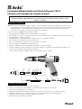
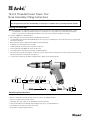
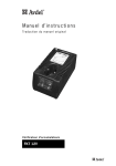
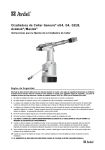
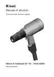
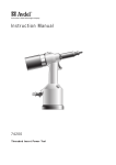
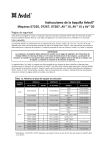
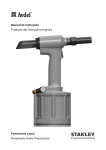
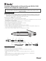
Ferramenta Hidropneumática de Elemento Roscado 74100 & 74101
Instruções de montagem do conjunto de ponta
IMPORTANTE
É necessário desligar o abastecimento de ar ao montar ou remover os conjuntos de ponta, excepto se receber
instruções em contrário.
INSTRUÇÕES DE MONTAGEM
Nota: Antes de montar o equipamento de ponta, certifique-se de que a embraiagem na ferramenta está ajustada para o binário correcto
para o elemento a ser colocado. É também essencial que se monte o Conjunto de Ponta correcto antes de se operar a ferramenta.
No Manual de Instruções da ferramenta 74100 & 74101, respectivamente nas secções Selecção de ferramenta e Conjuntos de
ponta, encontra os valores de binário e as referências do Conjunto de ponta completo.
Os números de peças em negrito referem-se à ilustração abaixo:
• Onde aplicável, insira a manga 8 e a mola de impulso 9 no invólucro de ponta 2.
• Unte as anilhas de encosto 3 e o rolamento de impulso 4 com massa de alta pressão (p. ex. Shell Alvania E.P.I.) e posicione-os pela ordem
apresentada abaixo no invólucro de ponta 2.
• Onde aplicável, monte o espaçador 5 através das anilhas de encosto e dos rolamentos de impulso.
• Insira o parafuso de accionamento 1 através do conjunto acima.
• Monte o veio motor 6 no furo sextavado na cabeça do parafuso de accionamento.
• Insira o esbarro 11 e a mola 10 na frente da ferramenta base.
• Aparafuse o adaptador 7 no cárter da embraiagem da ferramenta base (rosca à esquerda).
• Posicione o conjunto de ponta no adaptador. É necessário rodar o parafuso de accionamento à mão para alinhar o hexágono do veio
motor com o furo sextavado na garra frontal da ferramenta base.
• Coloque o invólucro de ponta no adaptador e aperte com a chave-inglesa (rosca à esquerda).
2
8
9
3
4
3
1
5
6
10
11
INSTRUÇÕES DE MANUTENÇÃO
A manutenção dos conjuntos de ponta deve ser feita semanalmente.
• Remova o conjunto de ponta completo utilizando o procedimento inverso das ‘Instruções de montagem’.
• Peças gastas ou danificadas devem ser substituídas.
• Verifique especialmente quanto a desgaste o parafuso de accionamento, as anilhas de encosto e o rolamento de
impulso.
• Lubrifique as anilhas de encosto e o rolamento de impulso com massa de alta pressão (p. ex. Shell Alvania E.P.I.).
• Verifique que as molas não estão deformadas. Substitua se for necessário.
• Monte de acordo com as instruções de montagem.
7
Ferramenta Hidropneumática de Elemento Roscado 74110
Instruções de montagem do conjunto de ponta
IMPORTANTE
É necessário desligar o abastecimento de ar ao montar ou remover os conjuntos de ponta, excepto se receber
instruções em contrário.
INSTRUÇÕES DE MONTAGEM
Nota: Antes de montar o equipamento de ponta, certifique-se de que a embraiagem na ferramenta está ajustada para o binário correcto
para o elemento a ser colocado. É também essencial que se monte o Conjunto de Ponta correcto antes de se operar a ferramenta.
No Manual de Instruções da ferramenta 74110, respectivamente nas secções Selecção de ferramenta e Conjuntos de ponta,
encontra os valores de binário e as referências do Conjunto de ponta completo.
Os números de peças em negrito referem-se à ilustração abaixo:
• Onde aplicável, insira a manga 8 e a mola de impulso 9 no invólucro de ponta 2.
• Unte as anilhas de encosto 3 e o rolamento de impulso 4 com massa de alta pressão (p. ex. Shell Alvania E.P.I.) e posicione-os pela ordem
apresentada abaixo no invólucro de ponta 2.
• Onde aplicável, monte o espaçador 5 através das anilhas de encosto e dos rolamentos de impulso.
• Insira o parafuso de accionamento 1 através do conjunto acima.
• Monte o veio motor 6 no furo sextavado na cabeça do parafuso de accionamento.
• Insira o esbarro 11 e a mola 10 na frente da ferramenta base.
• Aparafuse o adaptador 7 no cárter da embraiagem da ferramenta base (rosca à esquerda).
• Posicione o conjunto de ponta no adaptador. É necessário rodar o parafuso de accionamento à mão para alinhar o hexágono do veio
motor com o furo sextavado na garra frontal da ferramenta base.
1
• Coloque o invólucro de ponta no adaptador e aperte com a chave-inglesa (rosca à esquerda).
2
8
9
3
4
3
5
1
6
10
11
INSTRUÇÕES DE MANUTENÇÃO
A manutenção dos conjuntos de ponta deve ser feita semanalmente.
•
•
•
•
•
•
Remova o conjunto de ponta completo utilizando o procedimento inverso das ‘Instruções de montagem’.
Peças gastas ou danificadas devem ser substituídas.
Verifique especialmente quanto a desgaste o parafuso de accionamento, as anilhas de encosto e o rolamento de impulso.
Lubrifique as anilhas de encosto e o rolamento de impulso com massa de alta pressão (p. ex. Shell Alvania E.P.I.).
Verifique que as molas não estão deformadas. Substitua se for necessário.
Monte de acordo com as instruções de montagem.
7
Notas
Since 1922
Since 1 936
2010
AUSTRÁLIA
Infastech (Australia) Pty Ltd.
891 Wellington Road
Rowville
Victoria 3178
Tel:
+61 3 9765 6400
Fax: +61 3 9765 6445
[email protected]
CANADÁ
Avdel Canada Limited
1030 Lorimar Drive
Mississauga
Ontario L5S 1R8
Tel:
+1 905 364 0664
Fax: +1 905 364 0678
[email protected]
CHINA
Infastech (China) Ltd.
RM 1708, 17/F., Nanyang Plaza,
57 Hung To Rd., Kwun Tong
Hong Kong
Tel:
+852 2950 0631
Fax: +852 2950 0022
[email protected]
FRANÇA
Avdel France S.A.S.
33 bis, rue des Ardennes
BP4
75921 Paris Cedex 19
Tel:
+33 (0) 1 4040 8000
Fax: +33 (0) 1 4208 2450
[email protected]
Manual No.
07900-00812
ALEMANHA
Avdel Deutschland GmbH
Klusriede 24
30851 Langenhagen
Tel:
+49 (0) 511 7288 0
Fax: +49 (0) 511 7288 133
[email protected]
ÍNDIA
Infastech Fastening Technologies
India Private Limited
Plot No OZ-14, Hi Tech SEZ,
SIPCOT Industrial Growth Center,
Oragadam, Sriperumbudur Taluk,
Kanchipuram District,
602105 Tamilnadu
Tel:
+91 44 4711 8001
Fax: +91 44 4711 8009
[email protected]
ITÁLIA
Avdel Italia S.r.l.
Viale Lombardia 51/53
20047 Brugherio (MI)
Tel:
+39 039 289911
Fax: +39 039 2873079
[email protected]
JAPÃO
Infastech Kabushiki Kaisha
Center Minami SKY,
3-1 Chigasaki-Chuo, Tsuzuki-ku,
Yokohama-city,
Kanagawa Prefecture
Japan 224-0032
Tel:
+81 45 947 1200
Fax: +81 45 947 1205
[email protected]
Issue
A
A2
MALÁSIA
Infastech (Malaysia) Sdn Bhd
Lot 63, Persiaran Bunga Tanjung 1,
Senawang Industrial Park
70400 Seremban
Negeri Sembilan
Tel:
+606 676 7168
Fax: +606 676 7101
[email protected]
TAIWAN
Infastech/Tri-Star Limited
No 269-7, Baodong Rd,
Guanmiao Township,
71841 Tainan County,
Taiwan, R.O.C
+886 6 596 5798 (ext 201)
Tel:
Fax: +886 6 596 5758
[email protected]
SINGAPURA
Infastech (Singapore) Pte Ltd.
31 Kaki Bukit Road 3
#05-03/06 Techlink
Singapore, 417818
Tel:
+65 6372 5653
Fax: +65 6744 5643
[email protected]
REINO UNIDO
Avdel UK Limited
Pacific House
2 Swiftfields
Watchmead Industrial Estate
Welwyn Garden City
Hertfordshire AL7 1LY
Tel:
+44 (0) 1707 292000
Fax: +44 (0) 1707 292199
[email protected]
REPÚBLICA DA COREIA
Infastech (Korea) Ltd.
212-4, Suyang-Ri,
Silchon-Eup, Kwangju-City,
Kyunggi-Do, Korea, 464-874
Tel:
+82 31 798 6340
Fax: +82 31 798 6342
[email protected]
EUA
Avdel USA LLC
614 NC Highway 200 South
Stanfield, North Carolina 28163
Tel:
+1 704 888 7100
Fax: +1 704 888 0258
[email protected]
ESPANHA
Avdel Spain S.A.
C/ Puerto de la Morcuera, 14
Poligono Industrial Prado Overa
Ctra. de Toledo, km 7,8
28919 Leganés (Madrid)
Tel:
+34 91 3416767
Fax: +34 91 3416740
[email protected]
Change Note No.
07/176
11/072
Autosert® (equipment), Avbolt ®, Avdel®, Avdelmate ®, Avdel TX2000®, Avdelok®, Avex®, Avibulb ®, Avinox®, Avinut™, Avlug®, Avmatic®, Avplas®,
Avseal®, Avsert®, Avtainer ®, Avtronic®, Briv®, Bulbex®, Chobert®, Eurosert®, Fastriv®, Finsert®, Genesis®, Grovit®, Hemlok ®, Hexsert®, Holding
your world together®, Hydra®, Interlock ®, Klamp-Tite ®, Klamptite KTR ®, Kvex®, Maxlok ®, Monobolt ®, Monobulb ®, Neobolt®, Nutsert®, Nutsert
SQ®, Portariv®, Rivmatic ®, Rivscrew®, Speed Fastening ®, Squaresert®, Stavex®, Supersert®, Thin Sheet Nutsert ®, Titan®, T-Lok®, TLR®, TSN®,
TX2000®, Versa-Nut ®, Viking® e Viking 360 ® são marcas comerciais da Avdel UK Limited. Infastech™ e Our Technology, Your Success™
são marcas comerciais da Infastech Intellectual Properties Pte Ltd. Os nomes e logótipos de outras empresas mencionadas neste documento
podem ser marcas comerciais dos seus respectivos proprietários. Este documento tem objectivos meramente informativos. A Infastech não
oferece quaisquer garantias, explícitas ou implícitas, neste documento. Os dados apresentados estão sujeitos a alterações sem aviso prévio
em virtude do desenvolvimento contínuo do produto e do melhoramento da política. O seu representante local Avdel está à sua disposição
caso precise de confirmar esta última informação.
02.2011 • © 2010 Infastech
www.avdel-global.com
www.infastech.com
74100 & 74101 Threaded Insert Power Tool
Nose Assembly Fitting Instructions
IMPORTANT
The air supply must be disconnected when fitting or removing nose assemblies unless specifically instructed otherwise.
Fitting Instructions
Note: Before fitting the nose equipment, ensure the clutch on the tool is set to the correct torque for the insert being placed. It is also
essential that the correct Nose Assembly is fitted prior to operating the tool. Torque Values and complete Nose Assembly part
numbers can be found in the 74100 & 74101 Instruction Manual sections Tool Selection and Nose Assemblies respectively.
Item numbers in bold refer to illustration below:
• Where applicable, insert Sleeve 8 and Thrust Spring 9 into Nose Housing 2.
• Coat Thrust Washers 3 and Thrust Bearing 4 with high pressure grease (eg. Shell Alvania E.P.I.) and locate them in the order shown below
into the Nose Housing 2.
• Where applicable, fit Spacer 5 through Thrust Washers and Thrust Bearing.
• Insert Drive Screw 1 through the above assembly.
• Fit Drive Shaft 6 into the hexagonal hole in the Drive Screw head.
• Insert Stop 11 and Spring 10 into the front of the Base Tool.
• Screw Adaptor 7 into Clutch Housing of the Base Tool (left hand thread).
• Offer up the Nose Assembly to the Adaptor. It will be necessary to rotate the Drive Screw by hand to locate the hexagon on the Drive Shaft
with the hexagonal hole in the front jaw of the Base Tool.
• Screw the Nose Housing onto the Adaptor and tighten with a suitable spanner (left hand thread).
2
8
9
3
4
3
5
1
6
10
Servicing Instructions
Nose assemblies should be serviced at weekly intervals.
• Remove complete Nose Assembly using the reverse procedure to the ‘Fitting Instructions’.
• Any worn or damaged part should be replaced.
• Particularly check wear on Drive Screw, Thrust Washers and Thrust Bearing.
• Lubricate Thrust Washers and Thrust Bearing with high pressure grease (eg Shell Alvania E.P.I.).
• Check Springs are not distorted. Replace if necessary.
• Reassemble according to fitting instructions.
11
7
74110 Threaded Insert Power Tool
Nose Assembly Fitting Instructions
IMPORTANT
The air supply must be disconnected when fitting or removing nose assemblies unless specifically instructed otherwise.
Fitting Instructions
Note: Before fitting the nose equipment, ensure the clutch on the tool is set to the correct torque for the insert being placed. It is also
essential that the correct Nose Assembly is fitted prior to operating the tool. Torque Values and complete Nose Assembly part
numbers can be found in the 74110 Instruction Manual sections Tool Selection and Nose Assemblies respectively.
Item numbers in bold refer to illustration below:
• Where applicable, insert Sleeve 8 and Thrust Spring 9 into Nose Housing 2.
• Coat Thrust Washers 3 and Thrust Bearing 4 with high pressure grease (eg. Shell Alvania E.P.I.) and locate them in the order shown below
into the Nose Housing 2.
• Where applicable, fit Spacer 5 through Thrust Washers and Thrust Bearing.
• Insert Drive Screw 1 through the above assembly.
• Fit Drive Shaft 6 into the hexagonal hole in the Drive Screw head.
• Insert Stop 11 and Spring 10 into the front of the Base Tool.
• Screw Adaptor 7 into Clutch Housing of the Base Tool (left hand thread).
• Offer up the Nose Assembly to the Adaptor. It will be necessary to rotate the Drive Screw by hand to locate the hexagon on the Drive Shaft
with the hexagonal hole in the front jaw of the Base Tool.
1
• Screw the Nose Housing onto the Adaptor and tighten with a suitable spanner (left hand thread).
2
8
9
3
4
3
5
1
6
10
Servicing Instructions
Nose assemblies should be serviced at weekly intervals.
• Remove complete Nose Assembly using the reverse procedure to the ‘Fitting Instructions’.
• Any worn or damaged part should be replaced.
• Particularly check wear on Drive Screw, Thrust Washers and Thrust Bearing.
• Lubricate Thrust Washers and Thrust Bearing with high pressure grease (eg Shell Alvania E.P.I.).
• Check Springs are not distorted. Replace if necessary.
• Reassemble according to fitting instructions.
11
7
Notes
Since 1 936
2010
AUSTRALIA
Infastech (Australia) Pty Ltd.
891 Wellington Road
Rowville
Victoria 3178
Tel:
+61 3 9765 6400
Fax: +61 3 9765 6445
[email protected]
GERMANY
Avdel Deutschland GmbH
Klusriede 24
30851 Langenhagen
Tel:
+49 (0) 511 7288 0
Fax: +49 (0) 511 7288 133
[email protected]
INDIA
Infastech Fastening Technologies
India Private Limited
Plot No OZ-14, Hi Tech SEZ,
SIPCOT Industrial Growth Center,
Oragadam, Sriperumbudur Taluk,
Kanchipuram District,
602105 Tamilnadu
Tel:
+91 44 4711 8001
Fax: +91 44 4711 8009
[email protected]
CANADA
Avdel Canada Limited
1030 Lorimar Drive
Mississauga
Ontario L5S 1R8
Tel:
+1 905 364 0664
Fax: +1 905 364 0678
[email protected]
CHINA
Infastech (China) Ltd.
RM 1708, 17/F., Nanyang Plaza,
57 Hung To Rd., Kwun Tong
Hong Kong
Tel:
+852 2950 0631
Fax: +852 2950 0022
[email protected]
ITALY
Avdel Italia S.r.l.
Viale Lombardia 51/53
20047 Brugherio (MI)
Tel:
+39 039 289911
Fax: +39 039 2873079
[email protected]
FRANCE
Avdel France S.A.S.
33 bis, rue des Ardennes
BP4
75921 Paris Cedex 19
Tel:
+33 (0) 1 4040 8000
Fax: +33 (0) 1 4208 2450
[email protected]
Manual No.
07900-00812
JAPAN
Infastech Kabushiki Kaisha
Center Minami SKY,
3-1 Chigasaki-Chuo, Tsuzuki-ku,
Yokohama-city,
Kanagawa Prefecture
Japan 224-0032
Tel:
+81 45 947 1200
Fax: +81 45 947 1205
[email protected]
Issue
MALAYSIA
Infastech (Malaysia) Sdn Bhd
Lot 63, Persiaran Bunga Tanjung 1,
Senawang Industrial Park
70400 Seremban
Negeri Sembilan
+606 676 7168
Tel:
Fax: +606 676 7101
[email protected]
TAIWAN
Infastech/Tri-Star Limited
No 269-7, Baodong Rd,
Guanmiao Township,
71841 Tainan County,
Taiwan, R.O.C
+886 6 596 5798 (ext 201)
Tel:
Fax: +886 6 596 5758
[email protected]
SINGAPORE
Infastech (Singapore) Pte Ltd.
31 Kaki Bukit Road 3
#05-03/06 Techlink
Singapore, 417818
Tel:
+65 6372 5653
Fax: +65 6744 5643
[email protected]
UNITED KINGDOM
Avdel UK Limited
Pacific House
2 Swiftfields
Watchmead Industrial Estate
Welwyn Garden City
Hertfordshire AL7 1LY
Tel:
+44 (0) 1707 292000
Fax: +44 (0) 1707 292199
[email protected]
SOUTH KOREA
Infastech (Korea) Ltd.
212-4, Suyang-Ri,
Silchon-Eup, Kwangju-City,
Kyunggi-Do, Korea, 464-874
Tel:
+82 31 798 6340
Fax: +82 31 798 6342
[email protected]
USA
Avdel USA LLC
614 NC Highway 200 South
Stanfield, North Carolina 28163
Tel:
+1 704 888 7100
Fax: +1 704 888 0258
[email protected]
SPAIN
Avdel Spain S.A.
C/ Puerto de la Morcuera, 14
Poligono Industrial Prado Overa
Ctra. de Toledo, km 7,8
28919 Leganés (Madrid)
Tel:
+34 91 3416767
Fax: +34 91 3416740
[email protected]
Change Note No.
A
07/176
A2
11/072
www.avdel-global.com
www.infastech.com
Autosert® (equipment), Avbolt ®, Avdel®, Avdelmate ®, Avdel TX2000®, Avdelok®, Avex®, Avibulb ®, Avinox®, Avinut™, Avlug®, Avmatic®, Avplas®,
Avseal ®, Avsert®, Avtainer ®, Avtronic®, Briv®, Bulbex®, Chobert®, Eurosert®, Fastriv®, Finsert®, Genesis®, Grovit®, Hemlok®, Hexsert®, Holding
your world together®, Hydra®, Interlock®, Klamp-Tite ®, Klamptite KTR ®, Kvex®, Maxlok ®, Monobolt ®, Monobulb ®, Neobolt®, Nutsert®, Nutsert
SQ®, Portariv®, Rivmatic ®, Rivscrew®, Speed Fastening®, Squaresert®, Stavex®, Supersert®, Thin Sheet Nutsert ®, Titan®, T-Lok®, TLR®, TSN®,
TX2000®, Versa-Nut ®, Viking® and Viking 360 ® are trademarks of Avdel UK Limited. Infastech™ and Our Technology, Your Success™ are
trademarks of Infastech Intellectual Properties Pte Ltd. The names and logos of other companies mentioned herein may be trademarks
of their respective owners. This document is for informational purposes only. Infastech makes no warranties, expressed or implied, in this
document. Data shown is subject to change without prior notice as a result of continuous product development and improvement policy.
Your local Avdel representative is at your disposal should you need to confirm latest information.
02.2011 • © 2010 Infastech
Since 1922