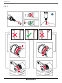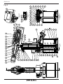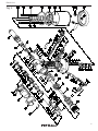
1
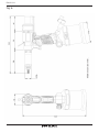
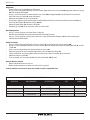
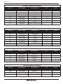
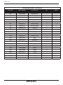
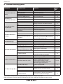
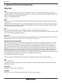
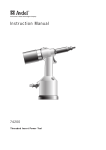
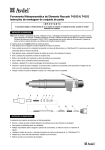
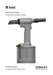
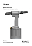
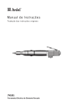
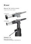
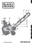
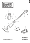
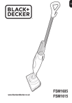
Service Manual
Original Instruction
Hydro-Pneumatic
Blind Rivet Nut Tool
ProSertTM XTN20 Blind Rivet Nut Tool – 74202
Hydro-Pneumatic Power Tool
ENGLISH
Fig. 1
K
F 13
80
12
20B
11
20B
46
14
19
13
I
15
C
12
A
75
22
31
30
739
Fig. 2
15
8
E7
A1
31
18
D6
30
19
14
5
4
13
3
C
B
2
2
B
ENGLISH
Fig. 3
900
3
4
A
13
61
62
9
69
47
46
10
11
12
48
73
14
39
16
2
1
53
52
4
49
59
7
51
60
8
38
15
37
17
71
B
40
B
72
SECTION A-A
SCALE 1 : 1
56
70
18
C
1
45
41
57
19
C
44
80
42
76
5
3
79
2
75
50
9
20
6
58
36
54
25
68
43
45
21
24
65
23
64
22
26
66
35
SECTION B-B
PRESSURE REGULATOR
SCALE 1 : 1
67
27
SECTION C-C
MANUAL REVERSE SWITCH
SCALE 1 : 1
63
EXTERNAL VIEW
SCALE 1 : 1
55
74
28
32
31
33
74
34
30
29
Fig. 4
SCALE 1 : 1
XXXX-XXXX
A
ENGLISH
43
21A
21B
20C
21E
42
21F
17M
20B
19
21D
21C
1M
23M
21M
22M
18M
3M
75G
41
19M
4M
20M
5M
75H
75F
18B
2M
70
8M
75A
72
75E
75B
75F
75C
18C
75D
6M
7M
10M
18A
1A
40
9M
44
11M
12M
45
57
13M
59
51
7
50
60
1
14M
46
15M
78
37
16M
71
8
61
62
9
69
17
64
38
22
32
33
68
63
31
54
67
47
65
26
23
11
15
56
16
66
10
24
39
35
12
14
36
27
48
34
25
73
55
77
28
29
79
30
74
6
58
76
5
53
52
2
3D
3A
3C
49
4
3B
Fig. 5
20A
74
80
13
ENGLISH
5
6
74202-02101
74202-02004
74202-02106
74202-02005
74202-02002
74202-02017
74202-02007
74202-02018
74202-02019
74202-02014
74202-02013
74202-02020
74202-02021
74202-02022
74202-02023
74202-02024
74202-02025
74202-02102
74202-02010
74202-02107
74202-02105
74202-02030
74202-02031
74202-02009
74202-02032
74202-02033
74201-12089
74202-02035
74202-02036
74202-02037
74202-02038
74202-02056
74202-02055
74202-02054
74201-12087
74202-02080
74202-02041
74202-02047
74202-02040
07265-02004
1
2
3
4
5
6
7
8
9
10
11
12
13
14
15
16
17
18
19
20
21
22
23
24
25
26
27
28
29
30
31
32
33
34
35
36
37
38
39
40
HANDLE ASSEMBLY
AIR CYLINDER
AIR PISTON ASSEMBLY
TIE ROD
RUBBER BOOT
AIR TUBE
ROD GUIDE
VALVE SLEEVE
VALVE SLIDER
BEZEL SWITCH
TRIGGER VALVE
TRIGGER
NOSE CASING
CHUCK NUT
MANDREL ADAPTOR
T JOINT
LOCKING NUT
DYNAMIC PISTON ASSY
STROKE ADJUSTER
END CAP ASSEMBLY
DISTRIBUTOR ASSEMBLY
MANUAL REVERSE SWITCH
MANUAL REVERSE SCREW
SPOOL VALVE
PRESSURE ROD
PRESSURE ROD SLEEVE
SPRING GUIDE
PRESSURE CATCH
REGULATOR
REGULATOR COVER
REGULATOR LOCK
SPRING
LOCKING BEARING
PRESSURE SPRING
REGULATOR SPRING
OIL ROD
SLEEVE
NOSE SPRING
CONNECTOR
LIP SEAL
DESCRIPTION
QT
Y
1
1
1
2
1
1
1
1
1
1
1
1
1
1
1
1
1
1
1
1
1
1
1
1
1
1
1
1
1
1
1
1
1
1
1
1
1
1
1
1
1
1
1
1
1
-
REC SPARES
Items in bold represent sub-assemblies which can be found on page 19.
PARNT NO
ITEM
41
42
43
44
45
46
47
48
49
50
51
52
53
54
55
56
57
58
59
60
61
62
63
64
65
66
67
68
69
70
71
72
73
74
75
76
77
78
79
80
ITEM
74202-02048
74200-12079
74202-02065
74202-02044
74202-02045
74202-02012
74202-02051
74202-02067
74202-02052
74202-02071
74202-02072
74202-02076
74202-02077
74201-12081
74202-02086
74202-02060
74202-02066
07003-00029
07003-00134
74202-02070
74202-02074
74202-02075
74202-02078
74202-02079
74202-02082
07003-00026
74201-12084
07003-00046
07003-00027
74200-12121
07003-00028
74202-02058
74202-02039
74202-02087
74202-02103
74202-02089
74202-02090
74202-02091
73200-02022
74202-02095
PARNT NO
HEAD SPRING
BALL (RUBBER)
SCREW M3 X 12
AIR TUBE
OIL PLUG
SUSPENSION RING
TRIGGER SPRING
TRIGGER PIN
AIR SPRING
WASHER
LIP SEAL
WASHER
TIE ROD NUT
LIP SEAL
WASHER
O RING
O RING
O RING
O RING
O RING
O RING
O RING
O RING
O RING
O RING
O RING
O RING
O RING
O RING
O RING
O RING
LIP SEAL
NOSE ROD
SCREW M3 X 8
AIR INLET ASSEMBLY
BASE CAP
FRONT LABEL
SIDE LABEL
SAFETY LABEL
LOCKING PIN
DESCRIPTION
1
1
2
2
1
1
1
1
1
1
1
2
2
1
1
1
2
1
1
1
3
1
1
2
3
1
1
1
1
1
1
1
1
3
1
1
1
2
1
1
QTY
1
3
1
1
2
3
1
1
1
1
1
1
1
1
1
1
1
2
2
1
1
1
1
2
2
2
1
REC SPARES
ENGLISH
All dimensions are in mm.
ENGLISH
Fig. 6
7
ENGLISH
Original Instruction
© 2015 Stanley Black & Decker, Inc.
All rights reserved.
The information provided may not be reproduced and/or made public in any way and through any means
(electronically or mechanically) without prior explicit and written permission from STANLEY Engineered
Fastening. The information provided is based on the data known at the moment of the introduction of this
product. STANLEY Engineered Fastening pursues a policy of continuous product improvement and therefore
the products may be subject to change. The information provided is applicable to the product as delivered by
STANLEY Engineered Fastening. Therefore, STANLEY Engineered Fastening cannot be held liable for any damage resulting from deviations from the original specifications of the product.
The information available has been composed with the utmost care. However, STANLEY Engineered Fastening
will not accept any liability with respect to any faults in the information nor for the consequences thereof.
STANLEY Engineered Fastening will not accept any liability for damage resulting from activities carried out
by third parties. The working names, trade names, registered trademarks, etc. used by STANLEY Engineered
Fastening should not be considered as being free, pursuant to the legislation with respect to the protection of
trade marks.
CONTENT
PAGE
1. Safety Definitions
9
2. Specification
2.1 Placing Tool Specification
2.3 Main Components List 11
11
12
3. Tool Setup 13
4.
13
13
14
14
Operating Instructions
4.1 Nose Equipment
4.2 Air Supply
4.3 Setting Instructions
5. Operating Procedure
15
6.
16
16
16
17
Servicing the Tool
6.1 Daily Servicing
6.2 Weekly Servicing
6.3 Priming
7. Maintenance
18
8. Trouble Shooting Guide
22
9. Hydraulic Oil General Safety Data
23
8
ENGLISH
This instruction manual must be read by any person installing or operating this tool with particular attention
to the following safety rules.
1. Safety Definitions
The definitions below describe the level of severity for each signal word. Please read the manual and pay
attention to these symbols.
DANGER: Indicates an imminently hazardous situation which, if not avoided, will result in death or serious injury.
WARNING: Indicates a potentially hazardous situation which, if not avoided, could result in death or
serious injury.
CAUTION: Indicates a potentially hazardous situation which, if not avoided, may result in minor or moderate injury.
CAUTION: Used without the safety alert symbol indicates a potentially hazardous situation which, if not
avoided, may result in property damage.
Improper operation or maintenance of this product could result in serious injury and property damage.
Read and understand all warnings and operating instructions before using this equipment. When using
power tools, basic safety precautions must always be followed to reduce the risk of personal injury.
SAVE THESE INSTRUCTIONS.
WARNING:
1. Do not use outside the design intent of Placing STANLEY Engineered Fastening Blind Rivet Nuts.
2. Use only parts, fasteners, and accessories recommended by the manufacturer.
3. Do not modify the tool in any way. Any modification to the tool is undertaken by the customer and will be the
customer’s entire responsibility and void any applicable warranties.
4. Prior to use, check for misalignment or binding of moving parts, breakage of parts, and any other condition
that affects the tool’s operation. If damaged, have the tool serviced before using. Remove any adjusting key or
wrench before use.
5. The tool must be maintained in a safe working condition at all times and examined at regular intervals for
damage and function by trained personnel. Any dismantling procedure will be undertaken only by trained
personnel. Do not dismantle this tool without prior reference to the maintenance instructions.
6. The operating supply air must not exceed 7 bar (100 PSI).
7. Operators and others in work area must wear ANSI Z87.1 CAN/CSA Z94.3 approved safety glasses with side
shields. Always wear safety glasses and ear protection during operation.
8. Dress properly. Do not wear loose clothing or jewellery. Keep your hair, clothing and gloves away from moving
parts. Loose clothes, jewellery or long hair can be caught in moving parts.
9. Do not operate a tool/machine that is directed towards any person(s).
9
ENGLISH
10. DO NOT operate tool with the nose housing removed.
11. Adopt a firm footing or a stable position before operating the tool.
12. Prior to use, inspect airlines for damage, all connections must be secure. Do not drop heavy objects on hoses. A
sharp impact may cause internal damage and lead to premature hose failure.
13. Do not lift the placing tool by the hose. Always use the placing tool handle.
14. Vent holes must not become blocked or covered.
15. Disconnect the air hose from the tool before performing any maintenance, attempting to adjust, fit or remove a
nose assembly.
16. Keep tool handles dry, clean, and free from oil and grease.
17. When carrying the tool from place to place keep hands away from the trigger to avoid inadvertent activation.
18. Never leave operating tool unattended. Disconnect air hose when tool is not in use.
19. Adequate clearance is required for the tool operators hands before proceeding.
20. Do not abuse the tool by dropping or using it as a hammer.
21. Keep dirt and foreign matter out of the hydraulic system of the tool as this will cause the tool to malfunction.
STANLEY Engineered Fastening policy
is one of continuous product development and improvement
and we reserve the right to change the specification
of any product without prior notice.
10
ENGLISH
2.Specification
The ProSert XTN20 hydro-pneumatic tool is designed for placing STANLEY Engineered Fastening Blind Rivet
Nuts through adjustment of the force and/or the stroke.
The ProSert XTN20 Tool is used to place Blind Rivet Nuts from a range of M3 to M10 when coupled with the
relevant nose equipment. Imperial nose equipment is also available to place UNC and UNF inch thread size
Blind Rivet Nuts
The safety instructions must be followed at all times.
2.1.Placing Tool Specification
Pull Force:
Air Supply Pressure:
Oil Pressure:
Stroke:
Weight:
Noise Level:
Vibration:
Motor Speed:
Material:
Avdel® Product
Range:
POP Nut®
Product Range:
Additional Features:
Pull @ stated pull pressure 5.0 bar
Min/Max
Pull (max)
Piston stroke
Including nose equipment
Uncertainty noise : K=3dB(A)
Uncertainty vibration K=0.1 m/s²
Forward & Reverse
-
17.65 kN
5-7 bar
230 bar
3-7 mm
1.59 kg
<75 dB(A)
<2.5 m/s2
2000rpm
Aluminium
Eurosert®
Thin Sheet Nutsert®
M3-M10
DK/DL
Euro Hexsert®/Hexsert®
High Strength Hexsert®
Squaresert®
Standard Nut*
M3-M10
Knurled Nut*
M4-M8
Closed End Nut*
M3-M10
Hexagonal Nut*
M4-M8
Tetra Nut*
M4-M8
HB Bolt*
M6-M8
Pipe Nut*
M6
Pull-to-Force operating mode
Pull-to-Stroke operating mode
Auto Spin On/Spin Off
Tool Free Mandrel fittings
Manual Reverse override
Hydraulic Lip Seals & O-rings
3968 lbf
72.5-101.5 lbf/in2
3336 lbf/in2
0.118-0.275 in
3.50 lb
<75 dB(A)
<8 ft/s2
2000rpm
Steel
Stainless Steel
M3-M10
M3-M10
M4-M10
M3-M8
M6-M8
M5-M8
M3-M8
M4-M6
M3-M8
M4-M8
M4-M8
M6-M8
M6
M4-M5
M3-M10
M6
M4-M6
M4-M6
M4-M6
-
Yes
Yes
Yes
Yes
Yes
Yes
Items with a * may require a mandrel adaptor kit (74202-02200 found in Accessories Manual 07900-01073). A complete ProSert
XTN20 (74202) tool is made up of the base tool (part number 74202-02000) and the appropriate nose assembly for the insert.
11
ENGLISH
2.3. Main components list ref fig. 1 & 2
Re-order
Spare part numbers Qty
A
Mandrel
B
Nose Tip
C
13
14
Lock Nut
Nose Casing
Chuck Nut
D
Reducing Sleeve
E
Drive Shaft
15
73
46
20B
F
80
19
I
75
22
31
30
12
K
Mandrel Adaptor
Nose Rod
Suspension Ring
Stroke Slider
Stroke Indication Markings
Stroke Locking Pin
Stroke Setter
Stroke Setter Recess
Air Inlet Assembly
Manual Reverse Trigger
Regulator Lock
Pressure Regulator
Trigger
Pin Punch
Complete nose assembly
M4
M5
M6
M8
M4
M5
M6
M8
M4
M5
M6
M8
M4
M5
M6
M8
-
M4
M5
M6
M8
All sizes are supplied with Lock Nut (c) 07555-00901.
For additional sizes please visit www.StanleyEngineeredFastening.com
12
07555-09004
07555-09005
07555-09006
07555-09008
07555-00904
07555-00905
07555-00906
07555-00908
07555-00901
74202-02021
74202-02022
07555-09104
07555-09105
07555-09106
07555-09108
07555-01004
07555-01005
07555-01006
07555-01008
74202-02023
74202-02039
74202-02012
74202-02092
74202-02095
74202-02010
74202-02103
74202-02030
74202-02038
74202-02037
74202-02020
07900-00624
07555-09884
07555-09885
07555-09886
07555-09888
1
1
1
1
1
1
1
1
1
1
1
1
1
1
1
1
1
1
1
1
1
1
1
1
1
1
1
1
1
1
1
ENGLISH
3. Tool Setup
IMPORTANT - READ THE SAFETY RULES ON PAGE 9 & 10 CAREFULLY BEFORE PUTTING INTO
SERVICE.
Before Use
•
•
•
Select relevant size nose equipment and install.
Connect the placing tool to the air supply. Test pull and return cycles by depressing and releasing the
trigger 12.
Set the tool for desired stroke/pressure.
CAUTION - correct supply pressure is important for proper function of the installation tool. Personal injury or
damage to equipment may occur without correct pressures. The supply pressure must not exceed that listed in the
placing tool specification.
4. Operating Instructions
IMPORTANT - READ THE SAFETY RULES ON PAGE 9 & 10 CAREFULLY BEFORE PUTTING INTO
SERVICE.
IMPORTANT - THE AIR SUPPLY MUST BE TURNED OFF OR DISCONNECTED BEFORE FITTING OR
REMOVING THE NOSE ASSEMBLY.
4.1 Nose Equipment (see Fig.2).
Fitting Instructions
Item numbers in bold refer to nose assembly components in fig 1.
• Air supply must be disconnected.
• If still fitted, remove the Nose Casing 13 and the Chuck Nut 14 while pulling back the spring loaded Nose
Rod 73.
• Insert Drive Shaft E into Mandrel Adaptor 15.
• Fit Mandrel A onto Drive Shaft E.
• Insert Reducing Sleeve D (if specified) into the Chuck Nut 14.
• Screw the Chuck Nut 14 onto the Mandrel Adaptor 15 while pulling back the spring loaded Nose Rod 73.
Tighten the Chuck Nut 14 clockwise.
• While holding the Tool, screw on the Nose Casing 13 and Nose Tip B with the nose tip Lock Nut C.
• The reverse operation is carried out for equipment removal.
With the tool still disconnected from the air supply, screw a Blind Rivet Nut onto the Mandrel manually.
• Position Nose Tip B on the Nose Casing and lock it with Lock Nut C so that the Mandrel A protrudes
slightly beyond the insert.
• Lock the Lock Nut C by turning clockwise with a spanner*. Remove the Blind Rivet Nut from Mandrel.
*Refer to items included in the Maintenance Kit 07900-09301 page 16.
13
ENGLISH
4.2 Air Supply
•
•
All tools are operated with compressed air at an minimum pressure of 5.0 bar.
Pressure regulators and automatic oiling/filtering systems to be used on the main air supply within 3
metres of the tool (see fig. 7).
Air supply hoses will have a minimum working effective pressure rating of 150% of the maximum pressure
produced in the system or 10 bar, whichever is the highest.
Air hoses must be oil resistant, have an abrasion resistant exterior and be armoured where operating
conditions may result in hoses being damaged.
All air hoses MUST have a minimum bore diameter of 6.4 millimetres.
•
•
•
3 METRES MAXIMUM
STOP COCK
(USED DURING MAINTENANCE
OF FILTER/REGULATOR OR
LUBRICATION UNITS)
MAIN SUPPLY
PRESSURE REGULATOR AND
FILTER (DRAIN DAILY)
LUBRICATOR
1/4" GAS
CONNECTION
Fig. 7
If above system is not available you can use the following alternative:
•
•
•
Before use or when first putting the tool into service, pour a few drops of clean, light lubricating oil into
the air inlet of the tool if no lubricator is fitted on air supply. If the tool is in continuous use, the air hose
should be disconnected from the main air supply and the tool lubricated every two to three hours.
Check for air leaks. If damaged, hoses and couplings must be replaced by new items.
If there is no filter on the pressure regulator, bleed the air line to clear it of accumulated dirt or water
before connecting air hose to the tool.
4.3 Setting Instructions
•
•
•
The stroke adjustment feature is mainly used for smaller insert sizes M3-M4.
If you are setting the tool for optimum stroke the Stroke Setter should be wound in to minimum stroke
(3mm) and the Pressure Regulator 30 be wound in to maximum setting.
If you are setting the tool for optimum pressure the Stroke Setter should be wound out to maximum
stroke (7mm) and the Pressure Regulator 30 be wound out to minimum setting.
When dealing with different grip thicknesses, it is always recommended that the tool is set for optimum
pressure rather than optimum stroke. Use the maximum grip condition to set optimum pressure.
14
ENGLISH
4.3.1. Stroke Adjustment (see Fig. 1A & 3).
To use this tool in stroke set operation, screw the Pressure Regulator 30 fully in to achieve full pressure then
adjust Stroke Setter to the desired stroke length:
•
•
•
•
•
•
•
•
•
•
•
Open Stroke Slider 20B
The Stroke Locking Pin 80 will be released.
Directional arrows indicate stoke direction.
Increase the stroke from the minimum until optimum deformation is obtained.
The scale gives an indication of the current stroke length.
Increments F shown are 3, 5 and 7mm on one side and 4 and 6mm on the opposite.
Line the rear of the Stroke Setter 19 up with these marks to achieve desired stroke length.
Each Recess I on the Stroke Setter 19 is equal to +- 0.1mm of stroke.
Close the Stroke Slider 20B before using in the application environment.
The Stroke Lock will activate when the Stroke Slider 20B is closed when the tool is in the upright position
The tool is now ready to operate.
4.3.2. Pressure Adjustment (see Fig. 1B & 3).
To use this tool in pressure set operation, wind the Stroke Setter 19 to 7mm, then screw the
Pressure Regulator 30 fully out to achieve minimum pressure then adjust to the desired pressure:
•
•
•
•
•
•
•
Initially the Blind Rivet Nut will not deform and the tool will spin off.
Screw in the Pressure Regulator 30 by 1 groove on the regulator body and test.
Repeat the operation with the Pressure Regulator 30 until optimum deformation is obtained.
1 notch on the Pressure Regulator 30 is equivalent to approximately 20N of pulling force.
After a successful Blind Rivet Nut deformation, check the Blind Rivet Nut and increase the force if
necessary.
Increase by 1-2 notches extra to allow for variation in the Blind Rivet Nuts.
The tool is now ready to operate.
5. Operating Procedure
Installing a Blind Rivet Nut (see Fig. 3).
To install a Blind Rivet Nut.
• Check that the correct Blind Rivet Nut has been selected.
• Push Blind Rivet Nut into the application.
• Check Nose Assembly is at right angle (90°) to the work.
• Push onto the Blind Rivet Nut with the tool to spin on.
• Once fully and correctly inserted, depress tool Trigger 12 switch to start installation cycle.
• Hold the Trigger 12 until the Blind Rivet Nut is completely set and the tool has disengaged completely.
In the event a Blind Rivet Nut becomes jammed in an application press the Manual Reverse Trigger 22 to
reverse the Mandrel A and spin off the Blind Rivet Nut. Alternately disconnect from the air supply and use the
4mm Pin Punch K supplied in the Maintenance Kit to wind off the Mandrel through the Nose Casing 13 shown
in the figure 1.
CAUTION - do not attempt to force the installation of an insert as this will cause damage to the tool and/or
application.
15
ENGLISH
6. Servicing the Tool
Regular servicing must be carried out by trained personnel and a comprehensive inspection performed
annually or every 500,000 cycles, whichever is sooner.
Cleaning and Maintenance
DISCONNECT AIR SUPPLY
Nose assemblies should be serviced at weekly intervals or every 5,000 cycles
CAUTION - Blow dirt and dust out of the main housing with dry air as often as dirt is seen collecting in and
around the air vents where the Pneumatic Cylinder connects to the plastic Handle Assembly. Wear approved eye
protection and approved dust mask when performing this procedure.
CAUTION - Never use solvents or other harsh chemicals for cleaning the non-metallic parts of the tool. These
chemicals may weaken the materials used in these parts.
•
•
•
•
•
Disconnect the air supply
Remove the complete nose assembly using the reverse procedure to the Fitting Instructions page 13(4.1).
Any worn or damaged part must be replaced by a new part.
Particularly check wear on Mandrel.
Assemble according to fitting instructions.
6.1 Daily Servicing
•
•
•
•
Check for air leaks. If damaged, hoses and couplings must be replaced by new items.
Check that the Nose Assembly is correct and fitted properly.
Check if the stroke of the tool is adequate to place selected Blind Rivet Nut. See Stroke Adjustment page
15 (4.3.1.).
Inspect the Mandrel A in the nose assembly for wear or damage. If any, replace.
6.2 Weekly Servicing
Part Number
07900-00624
07900-00632
07900-00225
•
•
Maintenance Kit 07900-09301
Description
4mm Pin Punch
17mm/19mm Spanner
5mm Hexagonal Wrench
Check for oil leaks and air leaks on air supply hose, fittings and tool.
Check oil level by laing the tool horizontally, open Oil Plug 45. If low, re-prime according to instruction
6.3 on page 17.
For servicing the following standard tools are needed (not supplied with Service Kit).
• 2mm Hexagonal Wrench
• 2.5mm Hexagonal Wrench
• 3mm Hexagonal Wrench
• 8mm Spanner
• 22mm Spanner or Socket
• 10mm Socket
• 14mm Spanner
• Pliers
• 10mm PTFE Tape
Spanners and Wrenches are specified across flats unless otherwise stated.
16
Qty
1
1
1
ENGLISH
6. 3 Priming
Priming is necessary after the tool has been dismantled and prior to operating. It may also be necessary to
restore the full stroke after considerable use, if the stroke has been reduced and fasteners are not now being
fully placed by one operation of the trigger.
Oil Details
The recommended oil for priming is Hyspin® VG32 available in 0.5l (part number 07992-00002) or one gallon
containers (part number 07992-00006).
Priming Procedure
All operations must be carried out on a clean bench, with clean hands in a clean area.
Ensure that the oil is perfectly clean and free from air bubbles.
Care MUST be taken at all times, to ensure that no foreign matter enters the tool, or serious damage may
result.
The tool must remain on its side throughout the priming sequence
•
•
•
•
•
•
•
•
•
•
Disconnect the air supply.
Place tool on its side, Oil Plug 45 side up.
With a 5mm hexagonal wrench, unscrew Oil Plug 45 and remove with Oil Seal Washer.
Fill tool with priming oil rocking gently to expel air.
Replace Oil Plug 45 with Oil Seal Washer and tighten.
Reconnect the air supply.
Depress the Trigger.
Disconnect the air supply.
Using a hexagonal wrench remove Oil Plug 45 and Oil Seal Washer.
Top-up with priming oil to reset level. Replace Oil Seal Washer and Oil Plug 45 and fully tighten.
It is necessary to fit the appropriate nose equipment and adjust the tool stroke prior to operating the tool.
17
ENGLISH
7. Maintenance
I M P O R TA N T
SAFETY INSTRUCTIONS APPEAR ON PAGE 9 & 10.
THE EMPLOYER IS RESPONSIBLE FOR ENSURING THAT TOOL
MAINTENANCE INSTRUCTIONS ARE GIVEN TO THE APPROPRIATE
PERSONNEL. THE OPERATOR SHOULD NOT BE INVOLVED IN
MAINTENANCE OR REPAIR OF THE TOOL UNLESS PROPERLY TRAINED.
Every 500,000 cycles the tool must be completely dismantled and inspected Components must be replaced
where worn or damaged. All ‘O’ rings and seals should be replaced with new ones and lubricated with
Molykote 55M grease before assembling.
WARNING - The airhose must be disconnected before any servicing or dismantling is attempted unless
specifically instructed otherwise.
- Dismantling operation be carried out in clean conditions.
- Before proceeding with dismantling, empty the oil from the tool. Remove oil plug 45, from the handle assembly and drain the oil into a suitable container.
- Prior to dismantling the tool it is necessary to remove the nose assembly. For simple removal instructions see page 13 (4.1)
For complete tool servicing we advise that you proceed with dismantling of sub-assemblies in the order
shown below. See Fig. 5 (page 5)
For complete tool strip down two additional tools a required.
Part Number
Description
07900-01074
Assembly Bullet
07900-01075
Seal Guide
QTY
1
1
Pneumatic Cylinder
• Remove Rubber Boot 5.
• Place tool with the base facing upwards in a vice fitted with soft jaws.
• Using a 8mm spanner remove the Tie Rod Nut 53 and Washer 52 the Air Cylinder 2 should move upward
under spring pressure.
• Remove Base Cap 76 with 3mm Hexagonal Wrench.
• Withdraw Air Piston Assembly 3 separate Assembly by holding Piston Rod in soft jaws and unscrewing the
Piston.
• Remove the spring 49
Rod Guide
• Unscrew the Rod Guide 7 using a 22mm socket and T bar.
• Withdraw the Rod Guide 7 and Washer 50. Remove the lip seal 51 and O ring 59.
Trigger
• Remove Trigger Pin 48.
• Remove Trigger 12.
• Unscrew Bezel Switch 10 using a 10mm Socket.
• Withdraw Bezel Switch 10, Trigger Valve 11 and Spring 47
18
ENGLISH
Regulator
• Unwind Pressure Switch 30 to its full extent.
Using a 2mm Hexagonal Wrench unscrew Screw 74 remove Pressure Switch 30 Regulator Lock 31, Spring
32 and Locking Bearing 33.
• Using a 14mm Spanner unscrew the Pressure Catch 28 the Regulator 29 should then be unscrewed
from the Pressure Catch 28 once withdrawn.
• Remove Spring 34 and Spring Guide 27.
• Using Pliers gently clamp onto the Pressure Rod 25 and Pull this will remove the Pressure Rod 25 and
Pressure Rod Sleeve 26 remove O Ring 66, 68.
• Remove Spool Valve 24, remove O Ring 65.
• Remove Lip Seal 54, to re-insert this seal use Seal Guide
Nose Equipment
• Using a 19mm Spanner unscrew Nose Casing 13.
• Retract the Nose Rod 73 and remove the Chuck Nut 14 by hand.
Using a 14mm Spanner and the 4mm Push Pin undo the Mandrel Adaptor 15 from the Locking Nut
17 and remove both items.
Head Assembly
• Using a 2mm Hexagonal Wrench unscrew Screws 74 and remove End Cap Assembly 20.
• Using a 2.5mm Hexagonal Wrench unscrew Screws 43 and remove Distributor Assembly 21, Ball 42 and Air
Tubes 44
• Fully unscrew Stroke Adjuster 19 and withdraw Spring 41.
• Remove Dynamic Piston Assembly 18 remove Lip Seal 72 and O Ring 70.
• Some residual oil may be expelled when the Dynamic Piston Assembly 18 is removed.
• Remove Static Lip Seal 40.
• To reassemble, use Assembly Bullet to mask Piston Rod 18B thread.
Manual Reverse Switch
• Remove Manual Reverse Screw 23.
• Withdraw Manual Reverse Switch 22, remove O-ring 64, 63.
Sub-Assemblies contained in Base Tool 74202-shown in exploded view
DYNAMIC PISTON ASSEMBLY 74202-02102
POSITION
PART NUMBER
DESCRIPTION
QTY
SPARES
18M
74202-02006
HYDRAULIC PISTON
1
-
18B
74202-02026
DRIVE PIN
1
-
18C
74200-12055
WASHER
1
2
-
74202-02104
AIR MOTOR ASSEMBLY
1
-
19
ENGLISH
AIR INLET ASSEMBLY 74202-02103
POSITION
PART NUMBER
DESCRIPTION
QTY
SPARES
74A
74202-02100
AIR FILTER
1
-
75B
07003-00026
O RING
1
-
75C
74202-02096
1/4 CONNECTION
1
-
75D
07003-00029
O RING
4
-
75E
74202-02097
MALE CONNECTION
1
-
75F
74202-02099
CIRCLIP
1
-
75G
74202-02098
FEMALE CONNECTION
1
-
DISTRIBUTOR ASSEMBLY 74202-02105
POSITION
PART NUMBER
DESCRIPTION
QTY
SPARES
21A
74202-02011
DISTRIBUTOR
1
-
21B
74202-02093
PIN
1
-
21C
74202-02066
O RING
2
-
21D
74202-02064
O RING
2
-
21E
74202-02063
O RING
1
-
21F
07001-0047
M4 GRUB SCREW
2
-
AIR PISTON ASSEMBLY 74202-02106
POSITION
PART NUMBER
DESCRIPTION
QTY
SPARES
3A
74202-02003
AIR PISTON
1
-
3B
74202-02015
PISTON ROD
1
-
3C
74202-02069
O RING
1
1
3D
07003-00029
O RING
3
3
END CAP ASSEMBLY 74202-02107
20
POSITION
PART NUMBER
DESCRIPTION
QTY
SPARES
20A
74202-02008
END CAP
1
-
20B
74202-02027
SLIDER
1
-
20C
74202-02092
END CAP STOPPER
1
-
ENGLISH
AIR MOTOR ASSEMBLY 74202-02104
POSITION
PART NUMBER
DESCRIPTION
QTY
SPARES
1M
74202-02028
MOTOR CASE
1
-
2M
74202-02110
HOUSING
1
-
3M
07555-09216
PIN
1
-
4M
74202-02111
HOUSING BLOCK
1
-
5M
07555-09215
BEARING
1
-
6M
74202-02112
MOTOR VANE
5
5
7M
74202-02113
MOTOR SPINDLE
1
-
8M
74202-02114
WASHER
1
-
9M
07555-09206
BEARING
1
-
19M
74202-02115
WASHER
1
-
11M
74202-02116
RING GEAR
1
3
12M
74202-02117
PLANET GEAR
3
-
13M
74202-02118
ROD
3
-
14M
74202-02119
SUN GEAR
1
-
15M
74202-02120
BEARING
1
-
16M
74202-02121
CIRCLIP
1
1
17M
74202-02043
MOTOR ROD
1
1
18M
74202-02060
O RING
1
-
19M
74202-02029
O RING
1
-
20M
07003-00315
O RING
1
-
21M
74202-02122
O RING
1
-
22M
74202-02123
PLUG
1
-
23M
07001-00479
M4 GRUB SCREW
3
-
21
ENGLISH
8. Troubleshooting guide
Symptom
Pneumatic motor runs
slowly.
Mandrel turns
independent of motor.
Insert will not place
onto Mandrel.
Tool/Blind Rivet Nut is
jammed.
Mandrel Breakage.
Possible Cause
Remedy
Air leak from motor.
Check for worn seals. Replace.
18
Low air pressure.
Increase air pressure.
14
Air way blockage.
Clear restiction.
18
Motor Vanes 6M jamming
Clean and lubricate.
18
Worn or damaged Drive Shaft E. Replace.
13
Worn or damaged Mandrel A.
Replace.
13
Chuck Nut 14 is loose.
Tighten Chuck Nut 14.
13
Incorrect Blind Rivet Nut thread
size.
Change to correct size Blind Rivet Nut.
13
Incorrect Mandrel A fitted.
Change to correct size Mandrel.
13
Worn or damaged Mandrel A.
Replace.
13
Nose equipment incorrectly
assembled.
Re-fit nose equipment.
13
Excessive stroke.
Reduce stroke.
3
Excessive pressure.
Reduce pressure.
3
Defective Blind Rivet Nut or
Mandrel A.
Press Manual Reverse 22.
Alternately use Pin Punch K to manually
remove the Blind Rivet Nut.
15
Excessive stroke.
Reduce stroke.
14
Excessive pressure.
Reduce Pressure.
14
Side load on Mandrel .
Hold tool square to application.
3
Chuck Nut 14 is loose.
Tighten Chuck Nut 14.
13
Connect air supply.
14
Adjust gap to 1.5mm/2mm.
4
No air supply.
Insufficient gap between
Tools does not spin On. Locking Nut 17 and Piston 18A.
Motor Rod 17M too short.
Trigger 12 inoperative.
Tool does not spin off.
Replace Motor Rod.
Lubricate tool at air inlet. If insufficient,
Air Motor jammed.
dismantle and clean thoroughly.
Static friction.
Depress and hold Trigger 12 a few times.
Low air pressure.
Increase air pressure.
Depress Trigger 12 several times.
Lubricate tool through air inlet.
Valve Slider 9 remains stuck.
If unsuccesful, dismantle, clean and
lubricate trigger components.
Chuck Nut 14 is loose.
Tighten Chuck Nut 14.
Trigger 12 released prematurely. Press and hold for entire cycle of tool.
Tool not reaching pressure or
Reduce pressure or stroke setting.
stroke.
Distributor 21A is stuck.
Lubricate.
Lubricate tool at air inlet. If insufficient,
Air Motor jammed.
dismantle and clean thoroughly.
Item numbers in bold refer to assembly drawings and parts list Pages 2,4,5, and 6.
Other symptoms or failures should be reported to your local, authorised distributor or repair centre.
22
Page
Ref.
5
18
14
4 & 18
13
14
4
18
ENGLISH
9. Hydraulic Oil General Safety Data
FIRST AID
SKIN:
Unlikely to cause harm to the skin on brief or occasional contact but prolonged or exposure may lead to
dermatitis. Wash skin thoroughly with soap and water as soon as reasonably practicable. Remove heavily contaminated clothing and wash underlying skin.
Launder contaminated clothing.
ORAL:
Unlikely to cause harm if accidentally swallowed in small doses, though larger quantities may cause nausea
and diarrhea.
If contamination of the mouth occurs, wash out thoroughly with water. Except as a deliberate act, the ingestion of large amounts of product is unlikely. If it should occur, do not induce vomiting; obtain medical advice.
Take person to nearest medical centre.
EYES:
Unlikely to cause more than transient stinging or redness if accidental eye contact occurs.
Wash eyes thoroughly with copious quantities of water, ensuring eyelids are held open. Obtain medical advice
if any pain or redness develops or persists.
DISPOSAL:
Remove all spills with inert absorbent material. Ventilate spill area. Place contaminated materials in a disposable container and dispose in a manner consistent with local regulations.
PROTECTING THE ENVIRONMENT:
Separate collection. This product must not be disposed of with normal waste. Should you find one day that
your product needs replacement, or if it is of no further use to you, do not dispose of it with regular waste.
Make this product available for separate collection. Separate collection of used products and packaging
allows materials to be recycled and used again. Re-use of recycled materials helps prevent environmental
pollution and reduces the demand for raw materials. Local regulations may provide for separate collection
of electrical products, at municipal waste sites or by the retailer when you purchase a new product. You can
check the location of your nearest authorised repair agent by contacting your local STANLEY Engineered
Fastening office at the address indicated in this manual. Alternatively, a list of authorised repair agents and full
details of our after-sales service and contacts are available on the Internet at:
www.StanleyEngineeredFastening.com
C.O.S.H.H. data for all hydraulic oils and lubricants is available on request from your tool supplier.
FIRE:
FLASH POINT: 200°C.
Extinguish with dry, chemical, foam or carbon dioxide. Do not enter confined space without self contained
breathing apparatus.
HANDLING:
Use barrier cream or oil resistant gloves.
STORAGE:
Undercover and consistent with local regulations for inflammable material.
23
Avdel UK Limited
Stanley House, Works Road
Letchworth Garden City, Hertfordshire SG6 1JY
Tel. +44 1582 900-000 · Fax -001
[email protected]
Find your closest STANLEY Engineered Fastening location on www.StanleyEngineeredFastening.com/
contact
For an authorized distributor nearby please check www.StanleyEngineeredFastening.com/econtact/
distributors
Manual Number
Issue
C/N
07900-09302
A
15/043
© 2015 Stanley Black & Decker, Inc.
Holding your world together®, Avdel®, Eurosert®, Nutsert®, Hexsert® and Squaresert® are registered trade marks
of Avdel UK Limited. ProSertTM is a trade mark of Avdel UK Limited. POP Nut® is a registered trade mark of
Newfrey LLC.
The names and logos of other companies mentioned herein may be trademarks of their respective owners.
Data shown is subject to change without prior notice as a result of continuous product development and
improvement policy.
Your local STANLEY Engineered Fastening representative is at your disposal should you need to confirm latest
information.