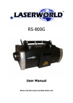
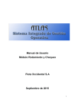
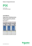
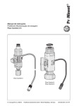
1
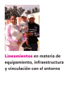
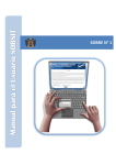
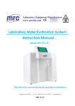
TERMO DE GARANTIA
Este produto está assegurado contra defeitos de fabricação e / ou
funcionamento, por 12 meses após a entrega ao cliente.
Todas as peças e componentes estão cobertos pela garantia, exceto quando
danificados por acidentes, imprudência, ou pela inobservância das instruções
de instalação de uso da geladeira.
WARRANTY TERMS
This product is assured against manufacture and/or operating defects for 12
months after delivery.
The warranty covers all parts and components, except when damaged by
accidents, imprudence or discrept of the usage and installation instructions of
the refrigerator.
MANUAL DE INSTRUÇÕES E GARANTIA
INSTRUCTION AND WARRANTY MANUAL
GELADEIRA GPM 70
MH22
UNIDADE COMPRESSORA EXTERNA 24VCC
DATA DE FABRICAÇÃO:
____ / ____ / ____
MANUFACTURE DATE:
____ / ____ / ____
FECHA DE FABRICACION:
____ / ____ / ____
N°:
12VCC
DATA INÍCIO GARANTIA / WARRANTY BEGINING /
/
24VCC
/_
FECHA INICIO DE LA GARANTIA:
REVENDEDOR / RESSELING:
MARCOPOLO S.A
CLIENTE / CUSTOMER:
ENDEREÇO / ADDRESS / DIRECCIÓN:
CIDADE / CITY / CIUDAD:
ESTADO / COUNTRY:
FONE / PHONE:
ATENDIMENTO AO CONSUMIDOR / CUSTOMER CALL CENTER / ATENCIÓN AL
CONSUMIDOR: 55 47 3542-3000
ELBER INDÚSTRIA DE REFRIGERAÇÃO LTDA
Rua Progresso, 150 - Centro.
89.188-000 - Agronômica - Santa Catarina - Brasil
ELBER - INDÚSTRIA DE REFRIGERAÇÃO
Rua Progresso 150 – Centro - 89188-000 - Agronômica - Santa Catarina - Brasil.
Made in Brazil
Phone/Fax: 55 47 3542-3000 / 55 47 3542-3018
www.elber.ind.br - [email protected]
FIG 06. Chicote Elétrico
Electrical Wiring
01
02
03
04
05
06
07
08
Legenda
Legend
Interruptor
Lâmpada
Termostato
Motor
Relê
Fusível
Sinal positivo painel
Ligar na bateria
Switch
Lamp
Thermostat
Engine
Relay
Fuse
Positive panel sign
Connect to the battery
15
FIG 04.
Perfuração do gabinete
Cabinet Perfuration
ÍNDICE
1.
2.
3.
4.
5.
6.
7.
8.
9.
10.
11.
16.
Características da geladeira
Especificações técnicas
Componentes e acessórios
Instalação e fixação da geladeira
Instalação elétrica
Funcionamento
Regulagem da temperatura
Melhor uso da geladeira e economia de bateria
Descongelamento e limpeza
Manutenção preventiva
Desenhos
Termo de garantia
04
04
05
05
06
06
07
07
07
07
12
13
CONTENTS
Refrigerators feature
Technical specifications
Components of the refrigerator
Installation and Fixation of the refrigerator
Electric wiring
Function
Temperature adjustment
Better usage of the refrigerator and battery economy
Defrosting and cleaning
Preventive maintenance
Figures
16. Garante
1.
2.
3.
4.
5.
6.
7.
8.
9.
10.
11.
FIG 05. Entrada e saída de ar
Air entrance and air exit
14
03
08
08
09
09
10
10
11
11
11
11
12
13
CARO USUÁRIO!
FIG 03. Componentes da geladeira
Refrigerators components
1
Você acaba de adquirir uma geladeira desenvolvida com tecnologia e
funcionalidade ELBER. Ficamos gratos pela sua escolha, pois são 20 anos de
aperfeiçoamento e tecnologia para você ter a melhor geladeira.
Leia com atenção as instruções contidas neste manual, e você usufruirá
plenamente das qualidades, vantagens e garantia dos produtos ELBER.
1. CARACTERÍSTICAS DA GELADEIRA
2
Feita para instalar em veículos automotores como ônibus, micro ônibus, motor
home, caminhões, barcos e outras aplicações. A geladeira ELBER é acionada
por bateria de 12VCC, tendo a opção para 24 VCC.
Permite ser utilizada como refrigerador para bebidas ou como freezer, somente
ajustando a graduação no termostato.
É uma geladeira forte feita para as mais severas condições de trabalho, aceita
inclinações de subidas e descidas de morros, tolera trepidações de buracos e
solavancos da estrada.
Toda estrutura do gabinete e dos componentes forma um conjunto resistente,
para a aplicação automotiva e também para a segurança do usuário com o
veículo em movimento. Possui válvula para drenar água de degelo e luz interna.
Para melhor conforto interno do veículo, esta geladeira é montada com UCE
(UNIDADE COMPRESSORA EXTERNA), o compressor (motor) é instalado do
lado de fora, no chassi do carro ou no bagageiro.
A UCE está preparada para suportar água, pó, sujeira da estrada, e pode ser
lavada juntamente com o veículo.
O gabinete de refrigeração está instalado no bar, dentro do veículo, e é
interligado à unidade compressora externa por uma mangueira politubos flexível
Elber, através de engates rápidos.
2. ESPECIFICAÇÕES TÉCNICAS
As geladeiras ELBER da linha GPM, foram desenvolvidas especialmente para
serem instaladas dentro de móveis e bares, em ônibus, microônibus e outras
aplicações.
Através da FIG 01 e FIG 02, você poderá conferir:
• Modelo, dimensões externas, peso, capacidade, consumo e graduação
de temperatura.
04
3
6
4
5
01
02
03
04
05
06
Legenda
Legend
Gabinete
Interruptor
Porta copos
Termostato
Tampa de manutenção
Lampada
Cabinet
Switch
Glass place
Thermostat
Compressor unit
13
3. COMPONENTES E ACESSÓRIOS
A embalagem do produto que você recebeu foi projetada para proporcionar
segurança no transporte do mesmo.
FIG 01. Especificações técnicas
Technical Especifications
Dimensões Externas
Outside Dimensions
Modelo
Model
Profund
Depth
GPM50
385mm
Largura
Width
755mm
Comprim
Lenght
514mm
Peso
Weight
(Kg)
38,2
Consumo
medio
Capacidade
Medium
Volume Interno
Capacity
Consumption
Inside Volume
Latas / cans
350ml
50litros/litres
50
12V
24V
4,2
2,8
Temperatura Interna
Regulável
Adjustable Inside
Tempurature
5 / -8º C
Através da (FIG 03) você poderá identificar os componentes da geladeira,como
mangueiras, unidade compressora externa, os acessórios de fixação e unho do
dreno.
4. INSTALAÇÃO E FIXAÇÃO DA GELADEIRA
(*) Consumo médio
4.1 Instalação e fixação da geladeira: Esta geladeira pode ser embutida em
móveis, não havendo necessidade de ventilação, pois o motor estará fora do
carro. Para fixação, está equipada com suporte embaixo e na parte superior
traseira(FIG 03). Passar a tubulação para fora do carro até o ponto onde será
instalada a unidade compressora.
Obs: Somente retirar as proteções de nylon dos engates no instante do
acoplamento.
4.2 Fixação da unidade compressora: A unidade compressora, embora feita
para condições severas de trabalho como água, poeira e sujeira da estrada,
deverá estar em locais ventilados e que não acumule barro. Após instalar o
gabinete e posicionar a unidade compressora, ajeitar a mangueira para
promover a ligação dos engates e dos plugs elétricos.
FIG 02. A Geladeira
The Refrigerator
12
Para conectar os engates:
• Posicionar a tubulação de forma que os engates fiquem encontrados.
• Retirar as tampas de nylon que servem de proteção dos engates, um
de cada vez, conforme vai sendo montado, evitando deixar aberto.
• Introduzir o engate macho no engate fêmea e rosquear a capa com
rosca para puxar a junção. O aperto da capa é feito com a mão até
encostar bem. Não usar ferramentas para dar aperto. O engate possui
dois anéis de vedação e foi desenvolvido para vedar somente com o
esforço possível das mãos.
Obs.: não precisa empurrar porque a rosca puxa.
• Após a junção dos engates, o gás estará liberado por toda a tubulação
do sistema. Evite abrir os engates novamente.
• Fixar as tubulações de maneira que elimine balanços ou atritos,
evitando quebrar ou furar com o tempo de uso.
Desta forma estará pronta para funcionar. O gás estará liberado pelo
acoplamento dos engates que abrem agulhas internas de retenção.
Obs: Não introduzir brocas ou parafusos na unidade compressora, pois poderá
afetar algum tubo de gás no seu interior danificando o produto (FIG 04).
5. INSTALAÇÃO ELÉTRICA
7.TEMPERATURE ADJUSTMENT
As geladeiras Elber são projetadas para serem acionadas pela bateria do
veículo. Sua voltagem (tensão) já vem definida de fábrica: 12 ou 24 VCC. Só é
possível trocar a voltagem com a substituição do motor, dos relês, e das
lâmpadas. A polaridade indicada no chicote elétrico deve ser respeitada para
obter melhor desempenho da geladeira. Não considerar a coloração dos fios
para orientar a polaridade. Na geladeira, a cor azul é do positivo e no veículo, a
cor azul poderá ser do negativo. Considerar as anilhas de identificação com (+)
e (–) existentes nos cabos. Utilizar condutor elétrico exclusivo da bateria para
ligar a geladeira.
Para acionar a geladeira no painel, ou à distância, utilizar um cabo de 1mm que
acionará o relê da geladeira. Este cabo deverá ter alimentação positiva(FIG
06). A inversão da polaridade não causa danos aos componentes, mas diminui
o rendimento da refrigeração, pois a curvatura da pá da hélice requer sentido
de rotação conforme indicado, para melhor fluxo de ar. Ao ligar, verificar se a
ventilação está funcionando. A Geladeira está equipada com fusível e relê
auxiliar que estão alojados dentro do compartimento de alumínio com tampa,
preso ao chicote elétrico. Este compartimento deve ser instalado no ponto mais
alto possível, embaixo do veículo(FIG 03), para não submergir quando o
veículo passar dentro de alagamentos (enchentes).
Obs: A UCE pode imergir na água, o fusível não(FIG 06).
Dimensionar o condutor elétrico (fio) de acordo com a distância entre a
geladeira e a bateria, conforme quadro a seguir:
The temperature adjustment is made through a thermostat. Check (FIG 03) and
the localization. When more higher programate more cold temperature, and
more big is the time work to the refrigerator.
BITOLA
12 V
CONDUTOR
2,4 mm
Para distância até
3m
CONDUTOR
4,0 mm
Para distância até
5m
CONDUTOR
6,0 mm
Para distância até
7m
CONDUTOR
10,0 mm
Para distância até
15 m
Para interruptor no painel, utilizar condutor 1,00mm até 50 metros
24 V
5m
9m
12 m
27 m
6. FUNCIONAMENTO
A geladeira possui sistema de refrigeração com gás ecológico R134a e
compressor de 12 ou 24 VCC, acionada pela bateria do próprio veículo. Você
observará o surgimento de gelo nas laterais internas, de cima para baixo, após
aproximadamente 30 minutos, o interior do gabinete estará gelado.
Depois de gelado, o termostato que regula a temperatura irá desligar e religar
automaticamente o compressor, mantendo a temperatura conforme ajuste,
economizando energia da bateria.
06
8. BETTER USAGE OF THE REFRIGERATOR. SUGGESTIONS FOR
BATTERY ECONOMY:
• Avoid leaving the cover open.
• Load the refrigerator always before you travel, because there is no problem
with the battery consumption while you are driving.
• In use, always keep the refrigerator loaded, even with bottles full of water.
This way, when the vehicle stands still and the products are already cold, the
refrigerator will operate less time. That means less battery consumption.
• Always maintain the drain covered, this avoids the entrance of heat and the
loss of efficiency.
9. DEFROSTING AND CLEANING
Every time, when ice is accumulated thicker than three centimeters on the
internal laterals, we recommend defrosting. For defrosting you only have to turn
off the refrigerator and open the drain.
Use water and neutral detergent for cleaning. Do not use chemical products
(alcohol, solvents, etc.), abrasive and hard sponges.
Not recommended procedures may spot and damage the surfaces and coatings
of the refrigerator.
10. PREVENTIVE MAINTENANCE
Accomplish preventive maintenance in accordance with the following:
• Clean the condenser to ensure a satisfactory air passage
• Check the packing of the doors or covers
• Check the latch of doors and covers.
11
5. ELECTRIC WIRING
7. REGULAGEM DA TEMPERATURA
Elber’s refrigerator is manufactured to connect directly to the vehicle battery.
Their voltage(tension) is determined by factory: 12 or 24 VCC. Voltage
interchange is only possible by changing the engine, relay and lamp.
The indicated polarity on the electric rope must be considered to achieve a
better performance of the refrigerator.
Do not consider the color of the wires for polarity orientation, on the refrigerator,
the blue color is positive and at the vehicle, the blue color could be negative.
You must consider the identification ring with (+) and (-) on the wires. Use
exclusive battery to electric conductor to connect the refrigerator.
To add the refrigerator on the panel, or a distance, use a cable of 1mm, which
put in action the refrigerator’s relay This cable must have a positive feed. The
inversion of the polarity doesn’t cause damages to the components, but
decrease the refrigerator’s efficiency, because the spade propeller curvature
needs a sense of rotation, correspondent to the indicated, for a better air
fluxion. When turns on, check if the ventilation is working. The refrigerator is
equiped with fuse and relay that are stored inside the aluminium compartment
with cover, fixed to the electrical wiring. This compartment may be installed in
the higher point as possible under the vehicle, to not submerge when the
vehicle cross inside the overflow (flood). Obs: The ECU may takes flood, the
fuse do not! Check electrical wiring fig. 06.
Measure the electric conductor (wire) according to the distance between
refrigerator and battery, in accordance with the table below:
A regulagem da temperatura é feita no termostato (FIG 03). Quanto mais alta a
temperatura programada no termostato(mais frio), maior será o tempo de
funcionamento da geladeira e por conseqüência, maior consumo de bateria.
GAUGE
CONDUCTOR
2,4 mm
For a distance up to
CONDUCTOR
4,0 mm
For a distance up to
CONDUCTOR
6,0 mm
For a distance up to
CONDUCTOR
10,0 mm
For a distance up to
Panel interrupter: Use 1.00 mm until 50 meters conductor
12 V
3m
5m
7m
15 m
24 V
5m
9m
12 m
27 m
6. FUNCTION
The refrigerator has a cooling system with ecological cooling gas R134a, and a
12 or 24 VCC compressor. Setting in motion by the vehicle’s battery, you may
observe the ice appear in the internal lateral, from up to down side, after about
30 minutes, the interior of the cabinet will become frozen. When frozen, the
thermostat for temperature will be adjustment turns the compressor
automatically off and on, keeping the temperature in accordance with the
setting, and low battery consumption.
,
10
8. MELHOR USO DA GELADEIRA E ECONOMIA DA BATERIA
• Evite deixar a porta aberta.
• Procure carregar a geladeira sempre antes de viajar, pois enquanto estiver
rodando não haverá problema com consumo de bateria.
• Em uso, mantenha sempre a geladeira carregada, mesmo que seja com
garrafas com água. Desta forma, quando o veículo estiver parado e os
produtos já frios, a geladeira irá funcionar menos tempo, isto é, menor
consumo de bateria.
• Manter o dreno sempre com a tampa, evitando a entrada de calor
prejudicando o rendimento.
9. DESCONGELAMENTO E LIMPEZA
Sempre que houver acúmulo de gelo nas laterais internas, com espessura
superior a três centímetros, recomenda-se fazer o degelo. Para degelar, basta
desligar a geladeira e abrir o dreno. Não utilizar objetos pontiagudos ou
cortantes para raspar o gelo.
Para limpar a geladeira utilize água e sabão neutro. Não usar detergentes
químicos(álcool, solventes, etc), produtos abrasivos e esponjas duras.
Procedimentos não recomendados poderão manchar e danificar as superfícies
e revestimento da geladeira.
10. MANUTENÇÃO PREVENTIVA
Realizar manutenção preventiva conforme abaixo:
• Limpar o condensador para permitir boa passagem de ar.
• Verificar a correia dentada.
• Verificar gaxeta de vedação e fecho das portas ou tampas.
07
DEAR CUSTOMER!
3. COMPONENTS OF THE REFRIGERATOR AND ACESSORIES
This refrigerator has been developed to be 12 or 24 VCC operated, with
ELBER´S functional and practical technology. Are more 20 years you have the
best working and tecnologie.Observing the instructions of this manual you will
make good use of the advantages, quality and warranty that ELBER´S product
has to offer.
The package of the product that you receipt, was project to provide safety on
the product transportation.
1. REFRIGERATOR FEATURES
4. INSTALLATION AND FIXATION OF THE REFRIGERATOR
It was made for installation in automotive vehicles such as: bus, coach, motor
home, trucks, boats and other applications directly connected to 12 or 24 VCC
batteries.
It may be used as refrigerator for beverage or as freezer according to the
adjustment of the thermostat.
It is a strong refrigerator made for several operation conditions. It endures
slope inclinations and hill declivities, tolerates trepidations and bumps from
holes on the street.
The entire structure of cabinet and components builds a very resistant unit,
designed for automotive application and also for the safety of the user when
driving the vehicle. It has a valve for the drainage of thawing water, gas spring
to keep the cover opened and internal light.
For a better internal confort of the vehicle, this refrigerator is mounted with
ECU = External Compressor Unit. The compressor (Engine) from this
refrigerator is installed outside, at the vehicle´s chassis or in the loader.
The ECU is prepared to support water, dust, road´s dirt and may be washed
together with the vehicle. Refrigeration cabinet is instaled on the bar inside the
vehicle and is interconnected to the External Compressor Unit, throught a
hose with flexible politubes Elber. This hose is connected to the compressor
unit, throught fast clamps.
4.1 Installation and fixation of the Cabinet: This refrigerator may be inserted
in furniture, because does not need access to the ventilation, because the
engine will be outside the vehicle. To fix, it is equipped with support under and
on the superior hinder part. (Check fig. 03).
Cross the pipeline outside the car, until the point where is installed the
compressor unit. Obs: Only remove the nylon protection from the clamps when
is connecting.
4.2 Installation and fixation of the Compressor Unit: The compressor unit
even made for several work conditions like water, dust and road´s dirty, has to
be in ventilated places and that do not have accumulation of mud. (Check
Elber´s technical instructions). After positioned the cabinet and compressor unit
installed, arrange the hose to provide the connection between the clamp and
the electrical plugs. To connect the clamps:
• Place the pipeline in a way that the clamps stay acrossed.
• Remove the nylon cover that serves as a protection to the clamps, one
each other time, according to the assembled. (Avoid to leave opened).
• Connect the male clamp on the female clamp and screw the cover to
pull the junction. The press of the cover is made by hands until lean
well. Do not use tools to press. The clamp holds two hindrance rings
and was developed only to close by hands effort. (Attention: Do not
need to push because the screw pulls).
• After the clamps junction, the gas will discharge for all over the pipeline
system. Avoid to open the clamps again.
• Attach the pipeline in a way that avoid swings or friction, because they
may break or pierce with a long time of utilization
This way it is ready to work. The gas will discharge by the clamps connector
that open internal needles of retention.
Obs: Do not introduce drills or screws in the compressor unit, because may
affect some gas tube in the interior damaging the product (fig04).
09
2. TECHNICAL SPECIFICATIONS
The refrigerator’s ELBER GPM line was made for installation in any space
available in the buses, microbuses and others, because it is ready to use
without necessity of extra furniture.
Observing the FIG 01 and FIG 02, you may check:
• Model, outside dimensions, weight, capacity, energy consumption and
graduation of temperature
08
Observing the FIG 03 you may identify the refrigerator components, as well the
UCE localization, ventilation grid, identification label, engine and compressor.
FIXAÇÃO DA GELADEIRA
FIXING THE REFRIGERATOR