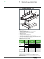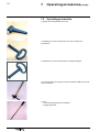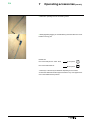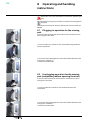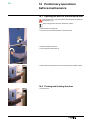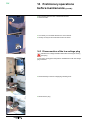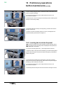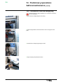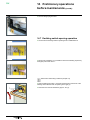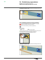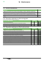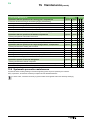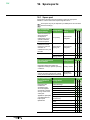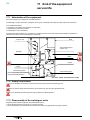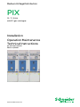
1
Medium Voltage Distribution
PIX
12 - 17 - 24 kV
with SF6 gas switchgear
Installation
Operation Maintenance
Technical Instructions
No. AMT NoT 056-02
Edition 12/2009
www.schneider-electric.com
Schneider Electric
35, rue Joseph Monier
CS 30323
92506 Rueil-Malmaison Cedex, France
www.schneider-electric.com
© Schneider Electric
All rights reserved to this technical instruction.
Reproduction and making available of this technical instruction, or extracts, to third parties are prohibited.
Only integral reproduction of this technical instruction is permitted with the written permission from Schneider Electric Energietechnik GmbH –
Sachsenwerk Medium Voltage.
Electronic copies in e.g. PDF-format or scanned version have the status “for information only”.
The only valid version of technical Instructions are always enclosed directly to the product in question by the factory.
PIX
Content
1
Schneider Electric at your service����������������������������������������������� 6
1.1 Your contacts������������������������������������������������������������������������������������ 6
2
2.1
2.2
2.3
2.4
2.5
2.6
With regards to this user manual������������������������������������������������� 7
Warranty������������������������������������������������������������������������������������������� 7
Eco-friendly design and utilization of the materials used����������������� 7
Normal operating conditions (as provided by standard IEC 60694)������ 7
Tough climate conditions������������������������������������������������������������������ 7
Other technical manuals which may be consulted��������������������������� 8
Tools and maintenance products (not supplied) necessary for
operations described in this instruction manual������������������������������� 8
2.7 Special instructions for operations and any intervention with
energized equipment������������������������������������������������������������������������ 9
2.8 Conventional symbols���������������������������������������������������������������������� 9
2.9 Tightening torques for standard assemblies (bolt + nut)������������������ 9
3
Presentation���������������������������������������������������������������������������������� 10
3.1 Description������������������������������������������������������������������������������������� 10
3.2 Space requirement and approximate weight of the PIX 12 kV,
”Incoming-Outgoing”, without packaging��������������������������������������� 10
3.3 Space requirement and approximate weight of the PIX 17 and 24
kV ”Incoming-Outgoing”, without packaging��������������������������������� 10
3.4 Designations of the moving parts��������������������������������������������������� 10
3.5 Presentation of the functional units������������������������������������������������ 11
3.6 Presentation of the L-TRI functional unit���������������������������������������� 14
4
Packaging - Handling - Storage�������������������������������������������������� 15
4.1 Transport - Delivery������������������������������������������������������������������������ 15
4.2 Packaging of the functional units��������������������������������������������������� 15
4.3 Packaging and handling of the FPX moving part�������������������������� 15
4.4 Drawing unit accessories��������������������������������������������������������������� 16
4.5 Reception/Acceptance������������������������������������������������������������������� 16
4.6 Handling of the functional unit and the moving part���������������������� 16
4.7 Storage������������������������������������������������������������������������������������������� 17
4.8 Intervention levels�������������������������������������������������������������������������� 18
4.9 Specific instructions for storage of less than 6 months����������������� 18
4.10 Special instructions for storage from 6 to 12 months�������������������� 18
4.11 Special instructions for storage from 12 to 24 months������������������ 18
5
5.1
5.2
5.3
5.4
5.5
5.6
5.7
Unpacking and installation of the equipment��������������������������� 19
Type of Building Structural Work���������������������������������������������������� 19
Unpacking functional units������������������������������������������������������������� 19
Identification of the functional unit�������������������������������������������������� 19
Handling the functional unit (always in vertical position)��������������� 20
Handling the moving part for placing it on the ground������������������� 20
Installation on the ground��������������������������������������������������������������� 22
Installation of a back-to-wall switchboard (top view)���������������������� 22
6
Installation������������������������������������������������������������������������������������ 23
6.1 Installation of functional units��������������������������������������������������������� 23
6.2 Fitting each of the functional units in place������������������������������������ 23
6.3 Connecting the panels������������������������������������������������������������������� 24
6.4 Preparation of the Busbar connection: access by the exterior������ 24
6.5 Opening the door of the functional unit������������������������������������������ 25
6.6 Removing the straps on the moving part compartment����������������� 25
6.7 Extracting the moving part from its compartment�������������������������� 26
6.8 Removing the removable floor������������������������������������������������������� 26
6.9 Preparation of the Busbar connection: access by the interior������� 28
6.10 Marking out the length of the bars������������������������������������������������� 28
6.11 Lay-outs depending on the number of bars����������������������������������� 29
6.12 Mounting of the support or segregation of the busbars����������������� 29
AMTNoT056-02
3
PIX
Content (contd.)
6.13 Example of a busbar connection���������������������������������������������������� 30
6.14 Remounting the internal arcing valves������������������������������������������� 31
6.15 Connecting up the earthing circuit������������������������������������������������� 31
6.16 Connection of the cables on functional units with solid flooring���� 32
6.17 Connection of the cables on functional units without a rear flooring
panel���������������������������������������������������������������������������������������������� 36
6.18 Remounting the drawing unit support�������������������������������������������� 37
6.19 Connection of low-voltage cables in the switch cabinet���������������� 37
6.20 Passage of the LV cables in the cable compartment��������������������� 37
6.21 Connection of a low voltage circuit in an upper cable trough�������� 38
6.22 Assembly of an internal arc deflector (optional)����������������������������� 38
6.23 Assembly of 24 kV insulating screens������������������������������������������� 38
7
Operating accessories����������������������������������������������������������������� 39
7.1 Transport trolley for truck��������������������������������������������������������������� 39
7.2 Operating accessories�������������������������������������������������������������������� 40
8
Operating and handling instructions����������������������������������������� 42
8.1 Plugging-in operation for the moving part�������������������������������������� 42
8.2 Unplugging operation for the moving part (compulsory before
opening the door)�������������������������������������������������������������������������� 42
9
Operation of the FPX moving part���������������������������������������������� 43
9.1 Manual arming of the circuit breaker (door open or closed)���������� 43
9.2 Closing and tripping the circuit breaker (door closed)������������������� 44
10 Operation of the GFX moving part (for 12 kV switchgear)������ 45
10.1 Operation of the contactor [door closed]���������������������������������������� 45
11
11.1
11.2
11.3
11.4
11.5
11.6
L-TRI functional unit�������������������������������������������������������������������� 46
Operating accessories�������������������������������������������������������������������� 46
Presentation of the functional unit�������������������������������������������������� 47
Reception and opening of the functional unit’s door���������������������� 47
Access to inside the functional unit������������������������������������������������ 47
Commissioning the functional unit������������������������������������������������� 48
Switching OFF the panel���������������������������������������������������������������� 48
12 Standard locking out and interlocking procedures������������������ 49
12.1 Operating mechanical interlocking������������������������������������������������� 49
12.2 Mechanical function interlock of panel L-TRI��������������������������������� 49
12.3 Locking out by padlock (not supplied) and by locks���������������������� 50
12.4 Interlocks using keylocks��������������������������������������������������������������� 50
12.5 Additional locking out and interlocking procedures������������������������ 51
12.6 Mechanical lock-out due to padlocks (not included in scope of supplies)��������51
13 Commissioning���������������������������������������������������������������������������� 52
13.1 Important notes������������������������������������������������������������������������������ 52
13.2 Inventory of tools and accessories on completion of work on site�������� 52
13.3 Pre-commissioning information������������������������������������������������������ 52
13.4 Principle pre-commissioning checks���������������������������������������������� 52
13.5 Energizing the ”Incoming” functional unit��������������������������������������� 53
13.6 Voltage test (VPIS indicators)�������������������������������������������������������� 53
13.7 Energising a second “Incoming”, supplied power from the same source��������54
13.8 Control of phase balance with a phase comparator (VPIS indicators)�������54
13.9 Voltage presence testing (VDS indicators)������������������������������������ 54
13.10Check phase coincidence using a phase monitor (VDS indicators)�����������54
14 Preliminary operations before maintenance ���������������������������� 55
14.1 Opening the door of the functional unit������������������������������������������ 55
14.2 Closing and locking the door���������������������������������������������������������� 55
14.3 Disconnection of the low voltage plug�������������������������������������������� 56
14.4 Removing the truck from the panel������������������������������������������������ 57
4
AMTNoT056-02
PIX
Content (contd.)
14.5 Inserting the truck into the panel���������������������������������������������������� 58
14.6 Connection of the low voltage plug������������������������������������������������ 59
14.7 Earthing switch opening operation������������������������������������������������� 60
14.8 Earthing switch closing operation��������������������������������������������������� 61
15 Maintenance���������������������������������������������������������������������������������� 62
15.1 Levels of maintenance������������������������������������������������������������������� 62
15.2 Preventive maintenance of the moving parts��������������������������������� 62
15.3 Preventive maintenance of the functional units����������������������������� 62
15.4 Systematic preventive maintenance���������������������������������������������� 63
15.5 Lubricating and greasing points����������������������������������������������������� 64
15.6 Replacement of a luminous indicator VPIS������������������������������������ 64
15.7 Anomalies and remedies���������������������������������������������������������������� 65
16 Spare parts������������������������������������������������������������������������������������ 66
16.1 Spare part��������������������������������������������������������������������������������������� 66
16.2 Switchgear identification����������������������������������������������������������������� 67
16.3 Storage conditions�������������������������������������������������������������������������� 67
16.4 Consumables for maintenance������������������������������������������������������ 67
17 End of the equipment service life����������������������������������������������� 68
17.1 Valorization of the equipment��������������������������������������������������������� 68
17.2 Safety instructions�������������������������������������������������������������������������� 68
17.3 Disassembly of the switchgear units���������������������������������������������� 68
17.4 Specific provisions concerning the circuit-breaker������������������������� 69
17.5 Dividing up and recycling of the materials used for PIX���������������� 69
18
AMTNoT056-02
Notes��������������������������������������������������������������������������������������������� 70
5
PIX
1 Schneider Electric at your
service
Electrical equipment requires especial attention and the compliance with
the provisions stipulated in this manual. Operating procedures and
maintenance work must be performed by qualified staff who are adequately
skilled for their tasks. Your local Schneider Electric Service will be at your
disposal at any time for support and advice.
Reminder: The mechanical lock-outs must be designed according to the
general safety provisions for electrical equipment and the specific
provisions for the network in question.
1.1 Your contacts
France:
Schneider Electric Appareillage Moyenne Tension Bd de la Résistance
BP 84019 F-71040 Mâcon Cedex 9
Tel. : 33 (0) 3 85 29 35 00
Fax : 33 (0) 3 85 29 36 30
Toll free: 0 800 40 27 62 24hrs/day 7 days a week
Germany:
Schneider Electric GmbH, Rathenaustraße 2, D-93055 Regensburg
Tel. : + 49 (0) 351 8200
Fax : + 49 (0) 351 820 2342
Belgium:
Schneider Electric Belgium S.A., Route Zénobe Gramme, 33 Zoning des
Plénesses B-4821 Dison
Tel. : +49 (0)9 41/46 20-0
Fax : +49 (0)9 41/46 20-4 18
Great Britain:
Schneider Electric UK Ltd Services, Frederick Road, Salford, M6 6QH,
England
Tel. : + 44 (0) 161 745 9090
Fax : + 44 (0) 161 745 4482
Switzerland:
Schneider Electric, Carl-Sprecher-Strasse 3, CH-5036 Oberentfelden
Tel. : + 41 (0) 62 737 33 33
Fax : + 41 (0) 62 737 31 80
6
AMTNoT056-02
PIX
2 With regards to this user
manual
© - Schneider Electric - 2011. Schneider Electric, the Schneider Electric logo and
any graphic version thereof are registered trademarks of Schneider Electric.
The other trademarks mentioned in this document, whether registered or not, are the
property of their individual owners.
This brochure applies to single busbar single-stage functional units 12 - 17.5 - 24 kV.
2.1 Warranty
Our equipment is subjected to factory inspection and testing according to
the applicable standards and provisions.
The correct function and the service life of the switchgear are influenced
greatly by compliance with the installation, commissioning and operating
conditions stipulated in this manual. Non-compliance with these provisions
may compromise warranty claims.
Any local provision which does not contradict the specifications of this
document, especially as regards safety for personnel and buildings, must
be complied with.
Schneider Electric cannot be held liable for the possible consequences of:
■■ non-compliance with the provisions contained in this manual, which refer
to international regulations
■■ non-compliance with the instructions of the suppliers of cables and
connecting accessories as regards application and installation
■■ any aggressive climate conditions (humidity, pollution etc.) prevailing in
the immediate environment of switchgear not suitable to this effect or not
protected accordingly.
This manual does not contain any instructions regarding the mechanical
lock-outs to be performed. The work described is performed on de-energized
(on installation) or mechanically locked-out (decommissioned) switchgear.
2.2 Eco-friendly design and utilization of
the materials used
The design and execution of our packaging materials corresponds (in
France) to the decree nP 98-638 dated 20 July 1998 as regards
environmental compatibility.
2.3 Normal operating conditions
(as provided by standard IEC 60694)
Admissible ambient temperature
The ambient temperature must be in the range from -5°C and +40°C.
The average value measured over a period of 24 hours must not exceed 35°C.
Installation altitude
High-voltage switchgear has been designed according to the appropriate
European standards and can be installed up to an altitude of 1000 m.
At higher installation altitudes, the reduced voltage endurance must be
taken into account.
In special cases, please contact the Schneider Electric Sales Department.
Air pollution
The ambient air must be free of dust, smoke, corrosive or combustible
gases, steam and salt.
Admissible air humidity
The average air humidity measured over a period of 24, hours must not
exceed 95%. The average vapour pressure, measured over a period of 24
hours, must not exceed 22 mbar.
The average air humidity measured over a period of one month, must not
exceed 90%.
2.4 Tough climate conditions
In an environment subject to frequent and sudden temperature changes,
condensation may occur after excessive ventilation, increased air humidity
or in the presence of warm air.
AMTNoT056-02
7
PIX
2 With regards to this user
manual (contd.)
Such condensation can be avoided by suitable arrangement of the room or
the building (appropriate ventilation, air driers, heating etc.).
In this case, the switchboard must be installed in a temperature-regulated
room (20°C).
Please consult Schneider Electric concerning any precautions or
specifications for the relevant situation.
2.5 Other technical manuals which may be
consulted
AMTNoT023
General lubrication
instructions
AMTNoT014
Gyrofluor GFA Contactor
SF6
Installation - Commissioning
- Operation - Maintenance
AGS 531360-01 UTX & MTX
Installation and operating
instructions
AMTNoT026
ORTHOFLUOR FPX
Circuit breaker
Installation - Commissioning
- Operation - Maintenance
AMTNoT027
BRH Mechanical control
mechanism
Installation - Commissioning
- Operation - Maintenance
AMTNoT053
DCX
Presentation Commissioning - Operation
AMTNoT054
DCX
Parameter setting by PC
Instructions Manual
AMTNoT069
DCX
Modbus Communication
AMTNoT077
PIX
Additional equipment
AMTNoT083
Specific drawing units
Test drawing unit
2.6 Tools and maintenance products (not
supplied) necessary for operations
described in this instruction manual
■■ Cutter
■■ Crow bar
■■ Open-ended spanners size 8 ; 13 ; 16 ; 18
■■ Ratchet wrench with socket sizes 8 ; 13 ; 16 ; 18
■■ Allen keys for hexagonal screws size 8 ; 10 ; 12
■■ Torque wrench with sockets size 13 ; 16 ; 18 and sockets
for hexagonal screws size 12
■■ Flat blade screwdriver
■■ Torx 25 screwdriver
■■ Cutting pliers
■■ 4 slings (capacity 1,000kg)
Product code
8
■■ Clean dry cloth
-
■■ Solvent (dielectric withstand >30kV), excluding any
chlorinated solvents
-
■■ Mobilplex 47, Mobilux EP3 from Mobil or Stabilube T6
from Sophos mechanical grease
01
■■ Grease for electrical contacts Electrolube 2GX from
Comindus
22
AMTNoT056-02
PIX
2 With regards to this user
manual (contd.)
2.7 Special instructions for operations and any
intervention with energized equipment
When commissioning and operating switchgear equipment under normal
conditions, the general electrical safety instructions (gloves, insulating
stool, etc.), as well as operation handling instructions should be respected.
All manipulations must be completed once started.
The lengths of time required for carrying out the operations mentioned in
the tables are given purely as an indication and depend upon conditions
on-site.
2.8 Conventional symbols
Code of a product recommended and marketed by
Schneider Electric
06
16
Value of the tightening torque
Example: 16 N.m
10
Mark corresponding to a legend
CAUTION! Remain vigilant! Precautions to be
taken in order to avoid any accident or injury.
FORBIDDEN! Do not do it! The compliance with
this indication is compulsory, non-compliance
with this stipulationmaydamage the equipment.
INFORMATION - ADVICE Your attention is
drawn to a specific point for installation or operation.
2.9 Tightening torques for standard
assemblies (bolt + nut)
Threaded fasteners without grease: assembly with ungreased washers.
Threaded fasteners with grease: assembly with greased washers.
Use grease referenced
01
Ungreased zinc-plated Greased stainless
steel threaded fasteners steel fasteners
Dimensions
(N.m)
(N.m)
Class 6.8
AMTNoT056-02
Class 8.8
A2-70
M6
7
9
7
M8
16
21
16
M 10
32
43
32
M 12
50
66
50
M 14
87
116
87
M 16
134
179
134
M 20
262
350
262
9
PIX
3
Presentation
3.1 Description
The PIX metal clad switchboard was designed so that all of the elements
are accessible from the front facing panel.
The functional unit is divided into 4 compartments: cables, moving part,
busbar and low voltage switchboard.
They are separated by metal partitions. The cable compartments, moving
part and busbar are all equipped with gas exhaust valves in case of any
internal arcing.
3.2 Space requirement and approximate
weight of the PIX 12 kV, ”IncomingOutgoing”, without packaging
Width of the functional units
(mm)
Depth (mm)
Heightdepending on the low
voltage box (mm)
650
800
1000
14051)
14052)
14052)
2130-2230- 2130-22302330
2330
2130-22302330
Approximate weights (kg) with
circuit breaker
720
770
820
Approximate weight (kg)
without circuit breaker
600
650
700
Approximate weight (kg) with
contactor
700
-
-
1)
2)
1605 (case for 40 kA internal arcing or 2 CT per phase)
1605 (case of 2 CT per phase)
3.3 Space requirement and approximate
weight of the PIX 17 and 24 kV ”IncomingOutgoing”, without packaging
Width of the functional units (mm)
800
1000
Depth (mm)
1605
1605
2330-24302530
2330-24302530
Approximate weight (kg) without circuit
breaker
620
650
Approximate weights (kg) with circuit
breaker
820
870
Height depending on the low voltage
box (mm)
3.4 Designations of the moving parts
10
Circuit breaker
FPX
Contactor
GFX
Bus-trunk
UTX
Voltage transformers on the
busbars
MTX
Test drawing unit
-
Drawing unit - visual inspection
-
AMTNoT056-02
PIX
3
Presentation (contd.)
3.5 Presentation of the functional units
”Incoming - Outgoing” feeder functional unit
1
18
2
17
3
4
5
Front panel
16
8
9
15
14
10
11
13
12
Legend
1
2
3
4
5
6
7
8
9
10
11
12
13
14
15
16
17
18
Internal arcing valve for the moving part compartment
Internal arcing valve for the busbar compartment
Busbars
Internal arcing valve for the cables compartment (or vbusbars)
Orthofluor FPX Circuit breaker
MTX ”Voltage transformers” moving part
GFX Contactor
Gas exhaust duct
Earthing switch
Current transformers
Cable clamping metal sheets
Medium voltage cables
Voltage transformers
Cable connection lugs
Access panel to the cable compartment
Access door to the moving part compartment
Access door to the command control box
Fixed points for slinging
AMTNoT056-02
11
PIX
3
Presentation (contd.)
”Motor Outgoing” functional unit (only in 12 kV)
1
18
2
17
3
4
7
Front panel
16
8
9
15
14
10
11
12
”Coupling” functional unit with earthing switch
1
18
2
17
3
4
5
Front panel
16
8
9
3
12
AMTNoT056-02
PIX
3
Presentation (contd.)
”Bus-risers with withdrawable voltage transformers” functional unit
1
18
2
17
3
Front panel
6
15
3
”Voltage measurement on busbars with withdrawable voltage transformers” functional units
1
18
2
17
3
Front panel
6
16
9
AMTNoT056-02
13
PIX
3
Presentation (contd.)
3.6 Presentation of the L-TRI functional unit
18
1
17
16
Front panel
9
2
3
4
10
11
12
13
5
8
14
6
15
7
Legend
1 Busbars
2 L-TRI switch
3 Gas exhaust duct
4 HV fuses
5 Earthing switch
6 Cable clamping metal sheets
7 Medium voltage cables
8 Cable connection lugs
9 Access panel to the busbar compartment
10 Panel fixing screws
11 Insulating plate (red)
12 Switch drive disk
13 Earthing switch drive disk
14 Access panel to the cable compartment
15 Door fixing screw
16 Access door to the command control box
17 Fixed points for slinging
18 Internal arcing valve for the moving part compartment
14
AMTNoT056-02
PIX
4 Packaging - Handling Storage
4.1 Transport - Delivery
The conditions and methods of transport are defined with the customer, at
the time of processing the contract. The packaging depends on the
transport conditions, storage and the nature of the product transported.
Functional units with a width of 1000 mm and their moving parts are
delivered vertically, in separate packaging.
Functional units with a width of 650, 750 and 800 mm can be
delivered vertically, with their moving part in the ”withdrawn/test”
position, strapped to the inside of their compartment.
4.2 Packaging of the functional units
■■ Packing the panel for truck and train transport:
□□ fastened to wooden bars,
□□ protected by a hood,
□□ front protected with foam material.
■■ Packing the panel for air and sea transport:
□□ using shrink-wrap and desiccant bags,
□□ packed in a wooden crate.
■■ State of the equipment on delivery:
□□ earthing switch „closed“,
□□ circuit breaker „strapped“ and „opened“, and „withdrawn/test“,
□□ mechanical control mechanism „disarmed“.
4.3 Packaging and handling of the FPX
moving part
For the lay-out in the packaging and handling of the circuit breaker, please
refer to instruction manual AMTNoT026 ”ORTHOFLUOR FPX Circuit
breaker”
For all shipments by air, the SF6 gas pressure is lowered to 0.5 relative bar.
A refilling and pressure adjustment kit is delivered with the device.
In cases where the switchgear travels under reduced pressure,
pump the circuit breaker back to nominal pressure before any closing
or tripping operation.
AMTNoT056-02
15
PIX
4 Packaging - Handling Storage (contd.)
4.4 Drawing unit accessories
Contains the elements required for installation and connection of the
switchgear panels to the busbars and cables.
4.5 Reception/Acceptance
■■ Ensure that the materials delivered is complete (list enclosed with the
accessories).
■■ Carry out a visual inspection of the functional units and moving parts.
In the event of an anomaly, make the necessary reserves with the
carrier.
The functional unit must remain vertical on its base, within its original
packaging, during any eventual storage period and until it arrives at
the location of its installation.
4.6 Handling of the functional unit and the
moving part
■■ Truck and train transport (max. 900 kg): by means of forklift truck.
■■ It is imperative to ensure that the forks of the truck are fully engaged
throughout the entire width of the functional unit.
■■ Packaging for air and sea transport: depending on the weight indicated
on the crate.
■■ It is imperative that the forks of the truck are fully engaged throughout the
entire width of the crate.
≥ 1m
16
■■ Pass 2 slings, supporting 1000 kg each under the crate on both sides of
the cross-bars.
■■ The weights of the crates are indicated on their sides.
AMTNoT056-02
PIX
4 Packaging - Handling Storage (contd.)
■■ Never tip the crates over.
In order to lift or deposit the moving part on the handling table, make
allowance for a jib crane (not supplied).
■■ Never handle the circuit breaker by its connecting plates.
The moving parts do not roll on the ground
■■ Never lift up a circuit breaker by lifting it under its chassis or under its
trolley.
4.7 Storage
The storage area must protect the equipment against any eventual
degradation agents, such as:
■■ water
■■ water vapour
■■ saline atmosphere
■■ pollution of all kinds
■■ micro-organisms.
o
+50 C
Please consult Schneider Electric for any derogations to these criteria.
o
- 25 C
AMTNoT056-02
Ensure that the equipment has really been packaged in accordance with
the demands of the forecasted storage period.
Avoid warehousing the equipment in premises that are subjected to
important and sharp temperature differences.
Ensure the total absence of aggressive vapours, sulphur dioxide (SO2) for
instance.
17
PIX
4 Packaging - Handling Storage (contd.)
4.8 Intervention levels
Definition
Levels
Operations ensured by the Customer
1
Operations necessitating training, to be carried out by an
approved third party
2
Work to be carried out only by Schneider Electric
3
4.9 Specific instructions for storage of less
than 6 months
Packaging under plastic covers
1 2 3
Inspect the packaging periodically
■
■
■
When unpacking: - Check the mechanical operation by
carrying out about several operations*
■
■
■
4.10 Special instructions for storage from 6
to 12 months
Packaging under heat-sealable linen, with the
presence of bags of desiccant
1 2 3
Inspect the packaging periodically (absence of perforation
amongst others)
■
■
■
When unpacking:
■■ Check the mechanical operation by carrying out about
several operations *
-
■
■
■■ Test the min. threshold level (AC, 85% rated Un; DC, 70%
of Un) for electrical operation of the coils
-
■
■
4.11 Special instructions for storage from
12 to 24 months
Packaging under heat-sealable linen, with
inspection hatch to change the bags of
desiccant
1 2 3
Inspect the packaging periodically (absence of perforation
amongst others)
■
■
■
Periodically replace the bags of desiccant
■
■
■
When unpacking:
■■ light maintenance work
-
-
■
■■ Check the mechanical operation by carrying out about ten
operations*
-
-
■
■■ Test the min. threshold level (AC, 85% rated Un; DC, 70%
of Un) for electrical operation of the coils
-
-
■
* Following air transport, the pressure of a SF6 circuit-breaker must
be restored to its nominal value before any mechanical functional
test.
18
AMTNoT056-02
PIX
5 Unpacking and installation
of the equipment
5.1 Type of Building Structural Work
The installation of a switchboard requires a sufficiently flat and even
concrete structure. The dressing of a top coat finish of cement with a
straight edge should eliminate any surface irregularities and declivities of
greater than 2mm per metre. A lay-out seated on levelled metal supports is
ideal, as they will also serve as a guide for the dressing of the cement
topcoat.
The overall flatness of the support surface should not show up any
deflection greater than 6 mm throughout the length of the switchboard.
5.2 Unpacking functional units
Unpacking the
functional units should
only take place on the
installation site.
To remove the
stringers, dismantle
the “cables”
compartment panel.
Tools required:
■■ Cutter for road and
rail transport
packaging
■■ Crow bar for air and
sea packaging.
Dispose of the
packaging waste
(wood, polystyrene)
via the appropriate
recycling channels.
For all handling
operations it is
advisable that you use
suitable protective
gloves.
Before handling a far
end functional unit,
remove its far end side
panel.
5.3 Identification of the functional unit
Position of
the plates
AMTNoT056-02
Check the technical characteristics shown on the nameplate, in comparison
with the initial order.
Information taken from this plate is necessary for any contact with
Schneider Electric.
Other identifications may be given, in accordance with the particular
specifications on the contracts.
19
PIX
5 Unpacking and installation
of the equipment (contd.)
5.4 Handling the functional unit (always in
vertical position)
■■ Four fixed slinging points are provided for on the roof of each functional
unit.
≥ 1m
■■ Lift the functional unit by 4 slings
□□ each one capable of supporting 1000 kg.
■■ Respect the minimum height as shown on the left diagram.
■■ Slide the functional unit along, using three cylindrical rollers of 30 mm
min. diameter.
■■ Thus moving it to its final installation point.
5.5 Handling the moving part for placing it on
the ground
■■ Moving part < 2000 A: hook up the 2 slings in the holes in the upper part
of the chassis.
20
AMTNoT056-02
PIX
5 Unpacking and installation
of the equipment (contd.)
■■ Moving part ≥ 2000 A: install the 2 slinging lugs (delivered with the
moving part).
■■ On the ground, prepare 2 stringers that will be aligned with the outer
edges of the truck.
FPX
stringers
(min. section 30x30 mm)
■■ Hook up the lifting beam and very slowly lift the moving part.
■■ The moving part does not roll along the ground. It must be placed on the
2 stringers.
■■ Place the moving part on the ground, on top of the stringers.
AMTNoT056-02
21
PIX
5 Unpacking and installation
of the equipment (contd.)
5.6 Installation on the ground
The limits of the structural civil engineering layout depend on the type and quantity of equipment to be installed.
Position the functional units whilst respecting minimum clearance distances
in front of, behind and to each side of the switchboard.
d2
5.7 Installation of a back-to-wall switchboard (top view)
Space (100 x 100 mm)
reserved for connection of
switchboard’s mass to the
ground electrode
d1
d3
d
PIX Switchboard
Space (200 x 50 mm) for the
passage of LV cables
22
Minimum clearances
PIX12
PIX17-24
d = 630 mm 730 mm
d1 > 100 mm 100 mm
d2 > 100 mm 100 mm
d3 126 mm 126 mm
AMTNoT056-02
PIX
6
Installation
6.1 Installation of functional units
For a switchboard composed of 1 to 8 functional units, it is recommended to begin installation of the equipment on the side
opposite the access to the premises.
For a switchboard with more than 8 units, begin the installation of the equipment by the middle of the switchboard.
6.2 Fitting each of the functional units in place
Suitable gloves must be worn during installation work.
The switching panels’ incoming feeders must be arranged according to the schematic diagram.
Each incoming feeder must be routed exactly perpendicular to the floor. Align the fronts.
Align further switchgear panels conducting the same verifications.
Anchor panels to the ground by three-point fastening.
■■ 2 in the lower cross-beams on the front (hex. bolt M10x30 + dowel pin),
■■ 1 at the outer rear side of the panel.
If necessary, block using the bases supplied with the equipment.
min. 1000 mm
Installationof deflector for internal faults
(see sect. 2.4).
min. 100 mm
H M10x30 bolts
+ ES10 washer
H M10x30 bolts
ES10 washer
+ L12 washer
+ plug
L12 washer
plug
Sectional view
0, 1 or 2 support pads
Top view
support
pads
AMTNoT056-02
23
PIX
6
Installation (contd.)
6.3 Connecting the panels
Connect panels to 7 securing points (hex. bolts M8x20).
Interconnect panels on the top rear using fastening links (4 hex. bolts
M8x20).
7 fastening points
1 bolt H M8x20
+ 2 washer M8
+ 1 washer ES8
+ 1 nut H M8
Mounting detail of
fastening link
6.4 Preparation of the Busbar connection:
access by the exterior
■■ Access to the busbars is possible via the removable roof on each
functional unit.
Temporary flooring
■■ Protect the upper surface of the metal plates by fitting a temporary
wooden floor panel.
■■ Unscrew the 10 fixing screws for each roof to gain access to the busbar.
24
AMTNoT056-02
PIX
6
Installation (contd.)
6.5 Opening the door of the functional unit
Recover the key and the operating handle from the accessories pack.
■■ Insert the key into its keyhole.
■■ Turn it in an anti-clockwise direction to unlock the door.
■■ Insert the handle into its hole.
■■ Turn it upwards: the door lifts up.
■■ Open the door: the handle can be removed but the key remains captive.
6.6 Removing the straps on the moving
part compartment
For functional units with a width of 650, 750 and 800 mm, the circuit
breaker may be delivered strapped into its compartment.
■■ Door open: the strapping points are located on the lower left and right
hand sides
1
3
■■ Unscrew the 2 screws (1) (Torx 25 screwdriver).
■■ Unscrew and remove the bolt H M8x25 (2).
■■ Remove the 2 strapping brackets (3).
■■ Screw in the 2 screws again (1).
2
AMTNoT056-02
25
PIX
6
Installation (contd.)
■■ Unscrew the 2 screws (4) (Torx 25 screwdriver).
■■ Unscrew and remove the bolt H M8x25 (5).
■■ Remove the 2 strapping brackets (6).
■■ Screw in the 2 screws again (4).
4
6
5
6.7 Extracting the moving part from its
compartment
To extract the moving part from its compartment, apply the
instructions § 14.3 & 14.4.
6.8 Removing the removable floor
If the functional unit is provided with a locking device by a lock on the
earthing switch, lock this earthing switch in the “Open” position, then
remove the key from the lock.
■■ Unscrew the 2 (or 3) fixing screws (8 mm Allen key) from the cable
compartment panel.
■■ Lift up and remove the panel.
■■ Mark the panel in relation to the appropriate functional unit.
3
■■ Insulating screens in 17-24 kV:
□□ remove the 3 fixing screws (1) from the support (2) for thescreens (3),
□□ remove the support,
□□ remove the 4 insulating screens.
1
2
■■ From inside the moving part’s compartment, remove the signalling
contacts unit (1 screw, 13 mm spanner).
■■ Suspend wiring harness within cable compartment.
26
AMTNoT056-02
PIX
6
Installation (contd.)
■■ Remove the 10 fixing screws from the removable floor (13 mm spanner).
Connector
Voltage indicator box
■■ In the case of a voltage presence box (VPIS or VDS), disconnect the
wiring before removing the flooring.
Floor beam
VPIS Connection
■■ Lift up the floor panel.
■■ Pull the floor panel towards you and slide it out of the compartent.
■■ Remove the 4 fixing screws to remove the support cross-bars (10 mm
spanner).
AMTNoT056-02
27
PIX
6
Installation (contd.)
6.9 Preparation of the Busbar connection:
access by the interior
In order to connect up the busbar and before penetrating the cable
compartment, install a temporary floor panel (planks of floor grating),
in order to protect the bottom metal plates and the cable passage.
Temporary Flooring
1
16
3
2
1
2
16
Temporary protective
flooring
4
3
Fixing the valves
16
Proceed with dismantling the two internal arc valves.
Unscrew the 2 screws H M8x25 (4) (13 mm spanner) fixing the valves to
the moving part compartment (2). Remove this valve.
Unscrew the 4 screws H M8x25 (3) (13 mm spanner) fixing the valves to
the busbar compartment (1). Remove this valve: access to the busbar is
now possible.
L
28
6.10 Marking out the length of the bars
Between functional units
L (mm)
Width (mm)
Width (mm)
Phase L1 Phase L2 Phase L3
650
650
644
644
644
650
800
696
719
744
800
800
794
794
794
650
1000
888
819
750
750
750
744
744
744
750
1000
913
869
825
800
1000
850
894
938
1000
1000
994
994
994
AMTNoT056-02
PIX
6
Installation (contd.)
6.11 Lay-outs depending on the number of bars
Number of bars:
1 bar
2 bars
3 bars
Cross section (mm²)
80x10
80x10
80x10
Arrangement of busbars
to vertical connections
1250 A
(60x10)
1600 A 1250 A
(80x10) (60x10)
1600 A
(80x10)
6.12 Mounting of the support or segregation
of the busbars
The busbar section segregation an optional equipment (at customer’s request).
The retaining plate is only required to ensure the mechanical stability of the
3150 A busbars.
The retaining plate is installed on principle for the coupler panel.
Support
AMTNoT056-02
Segregation (option)
Between functional units
Coupler/Riser functional unit
Before coupling the functional units, fix
the support for the mechanical
strength, or the segregation in order to
respect the specified leaktightness.
Before coupling the functional units,
fix the support ensuring the
mechanical strength of the bars.
29
PIX
6
Installation (contd.)
6.13 Example of a busbar connection
Insulation of busbars
only with 24 kV (or
optional).
■■ Before assembly, lightly brush the busbars contact areas with vaseline.
3
1
2
5
■■ Connect up each bar (1) on to its by-pass (2):
3 Upper connector housing with screw head housing.
4 Lower connector housing with 4 tapped holes.
5 Fix the assembly by 4 CHC M12 screws + 4 ES 12 washers.
4
30
AMTNoT056-02
PIX
6
70
Installation (contd.)
■■ Assembly and tightening of the 4 screws (10 mm Allen key).
□□ busbar : 45 mm screw,
□□ busbars : 55 mm screw.
6.14 Remounting the internal arcing valves
At the end of this work, proceed with re-assembly in the reverse order to the
operations described above (see § 6.9).
6.15 Connecting up the earthing circuit
■■ To connect two functional units together:
1 Unscrew the bolt H M8x35 (13 mm spanner) retaining the busbar link.
2 Slide this link through the functional units flange.
16
1
2
16
3
4
■■ In the adjacent functional unit:
■■ Unscrew the fixing screw.
3 Adjust the busbar link with the aid of slotted holes.
4 Bolt the busbar link on the 2 sides and tighten to indicated torque.
■■ Connect the earthing circuit linking all of the functional units to the room’s
earthing bar (Threaded fasteners H M12 and earthing cables not supplied).
49
AMTNoT056-02
31
PIX
6
Installation (contd.)
6.16 Connection of the cables on functional
units with solid flooring
In order to gain better access to the cables, remove the removable
floor panel (see section 6.8).
Presence of micro-switches on the earthing switch
■■ Preliminary operation: if the earthing switch is equipped with positioning
micro-switches, remove the power supply wiring strands.
■■ Remove the collars retaining the sheath (cutting pliers).
■■ Dismantle the micro-switch’s protective cover.
■■ Disconnect the sheath from the micro-switch’s terminal block.
■■ Pull out the wiring strands.
Fitting the cables in place
■■ Remove the lower front cross-bar (6 screws H M8x25, 13 mm spanner).
■■ Remove the front floor panel (6 screws H M8x25, 13 mm spanner).
32
AMTNoT056-02
PIX
6
Installation (contd.)
■■ Dismantle and recover the clamping collars as well as the grommets.
■■ Extract the bottom metal plates.
■■ Pass each cable by the floor openings and bring it out by the front of the
compartment to make up the cable ends.
■■ Cut out the grommet to the diameter of the cable.
■■ Fit this blanking piece on to the cable.
■■ Make up the cable end (fitting and crimping of the lug) in accordance with
the cable supplier’s recommendations.
Preparation of the undrilled connector connections
■■ Remove and tighten the connector in a vice (whilst taking care to protect it).
Connection
Tightening
AMTNoT056-02
33
PIX
6
Installation (contd.)
■■ Position and fix the lug to the said connector with quick tightening pliers.
Lug
Connection
Tightening
Tightening
■■ Punch and drill the holes by using those on the lug for centring.
Drilling
Lug
Connection
Tightening
Tightening
Two examples of drillings
Connection with 1 hole Ø 13 for:
■■ all lugs < 240 mm2
■■ 300 und 400 mm2 aluminium/copper lugs
4 holes Ø 9
Connection with 4 holes Ø 9 for:
■■ 500 und 630 mm2 aluminium/copper lugs
■■ 300 und 400 mm2 aluminium lugs
15
30
30
1 hole Ø 13
15
15
15
15
Fixing the cables
■■ Fix each cable to its connection lug:
□□ for cable > 400 mm2 (4 screws H M8, class 8.8, tightening torque: 16 N.m).
■■ For cable < 400 mm2 (1 screw H M10, class 8.8).
32
34
AMTNoT056-02
PIX
6
Installation (contd.)
■■ Assembly of 2 cables per phase: connect up the 2 cables to the first
connection lug.
First connection
lug
■■ Carry out the flanging for each cable on the cable itself.
Cable end
Tightening
flange
Grommet
Cable
Earthing braids
■■ Connect the 3 earthing braids to the functional unit’s earthing circuit
(screw H M8x25).
16
The earthing braids for the cables absolutely must pass above the
bottom metal plates.
Do not stick the phase markers (coloured adhesive tape) on the
reassemblies.
AMTNoT056-02
35
PIX
6
Installation (contd.)
L2 max.
50 mm
L
Fastening detail
L1 max.
Case of an assembly with a lock cup (adjustment)
Connection distances (mm)
PIX12
PIX17
PIX24
L
430
460
555
L1
390
420
515
L2
440
470
565
12
108
Cable assembly 95 mm2
L4 max.
L4 max.
L3 max.
6.17 Connection of the cables on functional units without a rear flooring panel
Cable assembly 300 mm2
12
Cable assembly 630 mm2
Connection distances (mm)
36
PIX12
PIX17
PIX24
L3
290
320
415
L4
410
440
495
AMTNoT056-02
PIX
6
Installation (contd.)
6.18 Remounting the drawing unit support
For remounting, reverse the order of steps according to § 6.8.
Perform mechanical function tests again with drawing unit (racking
in/racking out).
2
2
2
1
2
6.19 Connection of low-voltage cables in
the switch cabinet
■■ Access the terminal block (1) by the door on the box.
■■ Connect up the links between the functional units by passing through the
side openings (2) on the box.
■■ The customer can carry out the connection of exterior cables by the cable
trough (see § 6.20).
Exterior connection
6.20 Passage of the LV cables in the cable
compartment
■■ Lower panel removed to gain access to the wiring ducts.
■■ Left-hand side: no lower duct, reserved for Schneider Electric low voltage
cables.
■■ Right-hand side: reserved for passage of cables by the customer.
■■ Protection by a removable duct fixed by 3 M6 nuts (10 mm spanner).
AMTNoT056-02
37
PIX
6
Installation (contd.)
■■ Cut the caps as required to enable the low voltage cables to exit the
functional unit.
■■ Plug up the opening, around the cables, in order to preserve the specified
protection index.
6.21 Connection of a low voltage circuit in
an upper cable trough
4 caps
■■ Access the terminal block (1) and the ground bus (4) by removing the
cover on the upper wiring trough
(4 screws H M6x20).
■■ Connect up the links between the functional units by passing directly
from one wiring trough to the other.
■■ 2 et 3- Wiring troughs (see § 6.20).
1
3
4
2
■■ The customers can establish the external cable connections on their
own.
□□ either by the cable trough, by remounting through the righthand wiring
duct (see § 6.20).
□□ or from an upper cable trough and by the roof of the functional unit.
Exterior connection
Exterior connection
Top view
4
1
2
Legend
1
2
3
4
5
Terminal block
Wiring trough (right-hand)
Wiring trough (left-hand)
Customer’s connection
Inter-functional unit connections
3
5
6.22 Assembly of an internal arc deflector
(optional)
The deflector is installed in the roof of the low voltage box, whenever all of
the connections have been carried out (see § 6.2).
6.23 Assembly of 24 kV insulating screens
In the cable compartment, proceed with remounting the 4 insulating
screens (see § 6.8).
38
AMTNoT056-02
PIX
7
Operating accessories
7.1 Transport trolley for truck
1
2
3
4
5
12
6
11
10
7
9
8
Fig. 12.1
Transport trolley for truck
1
2
3
4
5
6
7
8
9
10
11
12
Autonomous interlocking of the racked-in truck on the trolley
Variable screw fastening of track
Positioning of track to adjust the various track widths
Track
Interlocking with panel
Variable screw fastening of unlocking bar
Positioning of unlocking bar to match various panel versions
Tray for accessories (lever, keys, handle)
Lever to lock / unlock the transport trolley on the panel. Table of trolley is lifted or lowered.
Unlocking bar. The truck is unlocked in the panel.
Handles of trolley
Slide to unlock the truck from the trolley
Rated
voltage Ur of
the panel
[kV]
≤ 12
Panel
width
[mm]
Truck
Item number
of trolley
650/800
HVX/UTX/MTX/CVX
EIB AE1 148-011
HVX/UTX (Ir = 2500 A)
EIB AE1 148-02
HVX/UTX (Ir = 3150 A)
AGS C74 125-01
HVX/UTX/MTX/CVX
EIB AE1 148-011
HVX/UTX (Ir = 2500 A)
EIB AE1 148-02
HVX/UTX (Ir = 3150 A)
AGS C74 125-01
800
HVX/UTX/MTX/CVX
EIB AE1 148-011
1000
HVX/UTX (Ir = 2500 A)
EIB AE1 148-02
1000
750
≤ 17.5
24
1000
Adjusting the track width
The trolley can be used for panel widths of 650, 750 and 800 mm:
■■ Release 3 screws on each track (Fig. 12.1, 2).
■■ Adjust the two tracks to the appropriate panel track width and check them.
Re-mount the six screws.
■■ Adapt position of unlocking bar (10) also to the appropriate panel (same procedure).
1
AMTNoT056-02
39
PIX
7
Operating accessories (contd.)
7.2 Operating accessories
■■ Opening and closing handle for the door
■■ Standard key* to lock and unlock the door of the ”drawing unit”
compartment
■■ Standard key* to lock and unlock the low-voltage switchgear
■■ Re-arming lever for the springs on the circuit breaker’s BRH mechanical
control mechanism
■■ Lever:
□□ for closing and tripping the circuit breaker,
□□ for tripping the GFX
40
AMTNoT056-02
PIX
7
Operating accessories (contd.)
■■ Standard* operating lever for the earthing switch
■■ Disengageable plugging-in and withdrawing crank handle for the circuit
breaker’s moving part.
References:
FPX & UTX with pincers - MTX - GFX
End-piece
FPX & UTX with bell ends
End-piece
* Other keys or levers may be delivered depending on the contract
Accessories delivered with the equipment and the only ones approved for
use on Schneider Electric products
AMTNoT056-02
41
PIX
8 Operating and handling
instructions
Opening the door is only authorised for maintenance operations (see
§ 15).
Respect the locking out procedures for interventions with equipment
energised.
Operating functions must be carried out with the door of the functional unit
closed.
8.1 Plugging-in operation for the moving
part
■■ Pass the crank handle through the hole in the door and introduce it into
the moving part’s drive shaft.
■■ Turn it in the direction of the arrow: the crank handle slowly penetrates
into the compartment.
■■ The CLACK of the disengagement of the crank handle indicates that the
moving part is “plugged- in“.
■■ Remove the crank handle.
8.2 Unplugging operation for the moving
part (compulsory before opening the door)
■■ Pass the crank handle by the hole in the door and introduce it into the
moving part’s drive shaft.
■■ Turn it in the direction of the arrow: the handle slowly leaves the
compartment.
■■ The CLACK of the disengagement of the crank handle indicates that the
moving part is “withdrawn”.
■■ Remove the crank handle.
42
AMTNoT056-02
PIX
9 Operation of the FPX moving
part
Legend
1
2
3
6
7
1
2
3
4
5
6
7
8
9
Location of the arming lever
Indicator light for the state of the circuit breaker (closed or tripped)
Operating counter
Handling handle
Low voltage plugging-in socket
Indicator light for the state of the springs (armed or released)
Manual closing and tripping handling button.
Technical data rating plate
Location for the plugging-in crank handle
8
4
5
9
9.1 Manual arming of the circuit breaker
(door open or closed)
Operation that can be carried out with the circuit breaker in the
position ”withdrawn/test”.
■■ Fit the arming lever into its housing.
■■ Turn the lever alternatively from top to bottom until the mechanism
makes a loud “CLACK” sound.
AMTNoT056-02
43
PIX
9 Operation of the FPX moving
part (contd.)
■■ The spring is “armed”: do not apply any more effort on the lever.
■■ Remove rhe arming lever.
9.2 Closing and tripping the circuit breaker
(door closed)
■■ Arm the BRH mechanical control mechanism on the FPX.
■■ Fit the closing and tripping lever into its orifice through the door.
■■ Introduce the lever into the axis of the operating button.
■■ Closing
To close the circuit breaker, turn to the right, following the arrow ”I”.
■■ The state of the circuit breaker is visible through the view port in the door.
■■ Tripping
To open the circuit breaker, turn to the left, following the arrow ”O”.
■■ The state of the circuit breaker is visible through the view port in the door.
44
AMTNoT056-02
PIX
10 Operation of the GFX
moving part (for 12 kV switchgear)
Legend
1
2
3
4
5
6
1
Operating counter (optional)
Location of the tripping lever (only on a latch-in contactor)
Low voltage plugging-in socket
Indicator light for the state of the contactor (closed or tripped)
Handling handle
Location for the plugging-in crank handle
4
2
5
3
6
10.1 Operation of the contactor (door closed)
■■ Magnetic action contactor:
□□ closing and tripping by electrical order.
■■ Latch-in contactor:
□□ closing by electrical order,
□□ manual tripping.
■■ Tripping
Take the lever and fit it through the door.
■■ Press 1.
■■ The tripped state (O) of the contactor is visible through the view port in
the door.
1
AMTNoT056-02
45
PIX
11 L-TRI functional unit
11.1 Operating accessories
■■ Handle for opening and closing the door.
■■ Standard key* to lock and unlock the door.
■■ Standard key* to lock and unlock the low-voltage switchgear.
■■ Operating levers.
■■ Red insulating plate for compartmentalisation with instructions label.
* Other keys may be delivered depending on the contract.
46
AMTNoT056-02
PIX
11 L-TRI functional unit (contd.)
11.2 Presentation of the functional unit
Legend
1
2
3
4
1 Access panel to the busbars
2 Fixing screws for the busbar panel
3 Valve pull control devices
4 Middle rail with sealing valve
5 Switch opening and closing mechanism
6 Location for the door handle
7 Earthing switch opening and closing mechanism
8 Location for the door key
9 Functional unit door
10 Door fixing screw
11 Switch position indicator
12 Earthing switch position indicator
11
5
7
6
8
9
10
12
11.3 Reception and opening of the
functional unit’s door (see marks on § 11.2)
Recover the key, the handle and the operating levers from the accessories pack.
Unscrew the fixing screws (10) from the door (9).
Insert the key into its keyhole (8). Turn in a clockwise direction. Insert the
handle into its hole (6). Turn it upwards: the door lifts up.
Open the door: the handle and the key remain captive.
11.4 Access to inside the functional unit
(refer to the marks in § 11.2)
■■ Door open, fuses removed.
■■ To remove the busbar’s upper panel, unscrew the 2 nuts (2).
■■ Lift up the middle cross-bar (4) and pull it towards you to remove it.
AMTNoT056-02
47
PIX
11 L-TRI functional unit (contd.)
11.5 Commissioning the functional unit
1 Set in place and fix the busbar panel.
2 Close and fix the door in place.
3 Remove the red insulating plate for compartmentalisation: the sealing
valve falls down by itself.
4 Open the earthing switch.
5 Close the switch.
1
3
5
4
2
11.6 Switching OFF the panel
4
4
3
3
5
1
2
1
2
3
4
5
48
Open the switch.
Close the earthing switch.
Take hold of the 2 shutter lifting rods.
Lift the rods and hook them into the notches.
Fit the red insulating plate for compartmentalisation.
AMTNoT056-02
PIX
12 Standard locking out and
interlocking procedures
12.1 Operating mechanical interlocking
The PIX functional units are equipped with mechanical function interlocks,
intended to avoid any kind of operating error.
These interlocks must be known before any operation is performed.
Interlocking
Function
Functioning
■■ Between the
plugging-in of the
moving part and the
installation of the low
voltage plug.
■■ The plugging-in of
the moving part is
impossible if the low
voltage plug is not
connected up.
■■ The shutter for
access to the
plugging-in control is
locked.
■■ Between the
plugging-in of the
moving part and the
earthing switch
”closed”.
■■ Plugging-in of the
moving part is
impossible if the
earthing switch is
closed.
■■ The plugging-in
crank handle
disengages.
■■ Between the closure
of the earthing switch
and the position of the
moving part.
■■ Closure of the
earthing switch is
impossible as soon as
the moving part is in
the course of being
plugged in or is
”plugged-in”.
■■ Operating the
control lever for the
earthing switch is
impossible: Do Not
Force It !
■■ Between the
plugging-in and the
closed state of the
moving part.
■■ Plugging-in of the
moving part is
impossible if the latter
is closed.
■■ The shutter for
access to the
plugging-in control is
locked.
■■ Between the closing
of the moving part and
plugging-in.
■■ Closing of the
moving part is
impossible outside of
the ”Plugged-in” or
”Test” positions.
■■ Electrical and
manual command
controls of the moving
part are impossible.
12.2 Mechanical function interlock of panel
L-TRI
Interlocking
Function
■■ Between
■■ Disconnector ON
disconnector, door and
earthing switch.
Functioning
■■ The earthing switch
is OFF.
■■ The door is closed.
■■ The add-in board
has been removed.
■■ Between
disconnector and
earthing switch
■■ Between the add-in
board and the door
■■ Earthing switch ON
■■ The disconnector is
OFF.
■■ Add-in board
present
■■ The disconnector is
OFF.
■■ Access to inside of
cable compartment
■■ The add-in board is
present.
■■ The earthing switch
is ON.
AMTNoT056-02
49
PIX
12 Standard locking out and
interlocking procedures (contd.)
12.3 Locking out by padlock (not supplied)
and by locks
The passage holes are provided to accept the shackle for padlocks
of 8 mm Ø.
The fitting of several padlocks on a single point necessitates the use
of an accessory that is not supplied.
■■ Mechanical lock-out of earthing switch by padlocks and other locks
■■ Mechanical lock-out for shutter (same principle for left-hand and righthand)
■■ Locking-out of the plugging-in
12.4 Interlocks using keylocks
1 Locking the earthing switch in the closed position.
2 Locking the earthing switch in the open position.
1
50
2
AMTNoT056-02
PIX
12 Standard locking out and
interlocking procedures (contd.)
■■ Rack-in interlock
3
12.5 Additional locking out and interlocking
procedures
Other locking-out and additional lokking devices can be supplied
depending on the particular specifications of the contract.
12.6 Mechanical lock-out due to padlocks
(not included in scope of supplies)
Through-holes are provided for 8 mm thick bars of padlocks.
If several padlocks are used in one location, an accessory (not
included in scope of supplies) is used.
AMTNoT056-02
51
PIX
13 Commissioning
13.1 Important notes
Prior to dispatch, PIX functional units are mechanically and electrically
tested.
If the material has been stored in a damp location, it is recommended that
the room be heated and the heating coils be energized for a period of 24
hours prior to installation.
Also check the leaktight devices in the room, the cable troughs, ventilation
etc.
13.2 Inventory of tools and accessories on
completion of work on site
Recover, draw up an inventory and tidy away all assembly tools and
objects not required in the switchboard.
Return the functional unit’s and circuit breaker’s operating accessories to
their respective storage positions
Post the technical Manual PIX in a clearly visible position.
13.3 Pre-commissioning information
Respect the General Safety Instructions for Electrical Applications and the
specific regulations for the network with regard to lock-outs.
Record the serial numbers and identifying marks on equipment and
switchgear while they are accessible. Tests and trials have already been
carried out in the factory.
Check with the plans and diagrams supplied along with the material. They
will describe the functionalities employed to carry out the level of operation
required.
13.4 Principle pre-commissioning checks
Visual inspection
Date Remarks Signature
■■ Ensure there are no foreign
bodies within the switchboard
■■ Check the external appearance
(no signs of blows, scratches on
the paintwork) - > carry out repairs
if needed.
■■ Check the conformity with the
protection index (leaktightness of
the functional units, various
blanking- off panels, etc.).
“Mechanical” checks
Date Remarks Signature
■■ Operating and interlock tests on
the access doors and removable
panels.
■■ Key-locked system tests.
■■ Checking mechanical locks,
(electrical jointing, power and
earthing circuits, etc.
Operations carried out on the
moving parts :
■■ Plugging-in and withdrawing,
■■ Connection of the LV socket,
■■ Arming, closing and tripping.
52
AMTNoT056-02
PIX
13 Commissioning (contd.)
Tests and trials
Date Remarks Signature
Dielectric tests
■■ Whilst taking all precautions
necessary, carry out a dielectric
test on the HV equipment and LV
cabling.
NB: These tests must be carried
out prior to electrical testing.
Electrical tests
■■ Check the continuity of the
earthing circuit.
■■ Check the connections on the LV
links.
■■ Test the correct operation of the
LV switchgear.
■■ Record the relay parameters.
State of switchgear
Date Remarks Signature
■■ Examine each moving part, in
particular the pluggingin pins
contacts
■■ Ensure that all the circuit
breakers are open and in the
isolating position the earthing
switches are open and the access
panels to the cables and to the
busbars are in place.
■■ Ensure that the voltage
transformer fuse indicator covers
have been removed (comply with
the instructions by the fuse
suppliers).
13.5 Energizing the ”Incoming” functional
unit
Energize the cables. In the case of a VPIS (IEC 61958) type voltage
presence, check that the luminous indicators are flashing.
In the case of a VDS type voltage detection (IEC 61243-5, HR system,
”high impedance”), successively connect up the tester to the 3 phases.
Check that it lights up in every case.
Energize the busbar. To do this, plug-in and close the circuit breaker (see §
Operation).
13.6 Voltage test (VPIS indicators)
2
4
1
3
AMTNoT056-02
The indication of ”voltage presence” is ensured in conformity with the
provisions of IEC 61958 within the range of service voltage defined on the
label (3).
To each of the 3 phases L1, L2 and L3 (1) there is a corresponding flashing
indicator (2).
A connection point (4), for each phase, is accessible on the front face of the
luminous indicator in order to connect the phase comparator.
The indication of a VPIS, by itself, is insufficient to ensure that the system is
de-energized: if the operating rules demand it, then the appropriate voltage
detectors must be used to that effect, in compliance with IEC 61243-5.
53
PIX
13 Commissioning (contd.)
13.7 Energising a second “Incoming”,
supplied power from the same source
Energize the cables. Check for the presence of voltage (see § 13.5).
Check the phase balance (see §13.8 or 13.9) before commissioning.
13.8 Control of phase balance with a phase
comparator (VPIS indicators)
■■ Connect the 2 phase comparator cables (optional) on to 2 phases of the
same functional unit. The light should light up: Showing the comparator is
working.
■■ Check the phase balance with the aid of a phase comparator already
checked. If the phases are out of balance, inspect the cable connections.
■■ Phases are balanced: light out
■■ Phases out of balance: light on
■■ Phases are balanced: light out
■■ Phases out of balance: light on
13.9 Voltage presence testing (VDS indicators)
■■ Voltage indicator housing
■■ Detector of the presence of voltage type KSP HR2 (optional).
13.10 Check phase coincidence using a
phase monitor (VDS indicators)
■■ Phase comparator for HR system (Type ORION 3.0, Horstmann GmbH)
Phase comparators are optionally available and not included in the scope
of supplies.
Make sure to check phase coincidence before connecting different supply
lines for the first time.g.
54
AMTNoT056-02
PIX
14 Preliminary operations
before maintenance
14.1 Opening the door of the functional unit
Opening tbe door is only authorised for the maintenance operations
mentioned in § 13.
The moving part must be in the “withdrawn” position.
■■ Insert the key into its keyhole.
■■ Turn it in an anti-clockwise direction to unlock the door.
■■ Insert the handle into its hole.
■■ Turn it upwards: the door lifts up.
■■ Open the door: the handle can be removed but the key remains captive.
14.2 Closing and locking the door
■■ Close the door
AMTNoT056-02
55
PIX
14 Preliminary operations
before maintenance (contd.)
■■ Move handle down: the door is lowered and locked.
■■ Remove handle.
■■ Turn the key in a clockwise direction: the door is locked.
■■ The key can only be removed when the door is closed.
14.3 Disconnection of the low voltage plug
Isolate the low voltage auxiliaries before disconnecting the moving
part’s plug.
■■ Door open: moving part in the position ”withdrawn/test” with low voltage
plug connected.
■■ Pull horizontally on the low voltage plug unlocking lever.
■■ Disconnect the plug.
56
AMTNoT056-02
PIX
14 Preliminary operations
before maintenance (contd.)
■■ Remove the wiring sheath.
■■ Raise and store all of the low voltage connections in the space reserved
for it above the moving part.
■■ Low voltage plug stored in its housing.
14.4 Removing the truck from the panel
■■ Adjust rails and unlocking bar of trolley to the correct track width of the
truck (see Chapter 7.1).
■■ Turn lever to the left (picture left, 1). The trolley is lifted on the front.
1
■■ Approach trolley to the panel so that the lateral guides (picture left, 2) are
close to the panel, and turn lever (1) back to the right. The trolley is locked
on the panel (3).
3
3
2
AMTNoT056-02
57
PIX
14 Preliminary operations
before maintenance (contd.)
■■ Push unlocking bar (picture left, 4) forward to its stop. The latching of the
truck in the panel is released.
5
■■ Turn lever back to the left (6). The trolley is lifted on the front, and
removed from the panel.
■■ Pull truck (HVX, CVX, FPX, GFX) onto the trolley via the handles (5) until
it snaps in on the trolley audibly.
4
6
■■ Pull trolley with the truck away from the panel (7) and turn lever back to
the right to lower it (8).
■■ Now the truck can be raised by means of a crane, and deposited. For
further information, please refer to Chapter 5.5.
7
8
14.5 Inserting the truck into the panel
Trucks and panels can be given matching coding, optionally. This is
to prevent a truck from being racked completely into the panel if the
rated data do not match.
■■ Turn lever to the left (picture left, 1). The trolley is lifted on the front.
2
3
1
■■ Approach trolley to the panel via the handles (2) so that the lateral guides
(3) are close to the panel, and turn lever back to the right (4). The trolley is
locked on the panel.
4
6
■■ Press left-hand unlocking button (picture left, 5) and slip truck briefly
beyond the ratchet lever. Subsequently, slide truck into the panel using the
handles (6), until it is latched in the panel.
■■ Turn lever back to the left (7). The trolley is lifted on the front, and
removed from the panel.
■■ Pull trolley back from the panel and turn lever back to the right to lower it.
5
7
58
AMTNoT056-02
PIX
14 Preliminary operations
before maintenance (contd.)
14.6 Connection of the low voltage plug
Ensure that the low voltage auxiliaries are cut off before connecting
the low voltage plug.
■■ Pull out the low voltage plug from its housing.
■■ Fit the wiring sheath into the hooks fixed on to the moving part’s front
plate.
■■ Present the low voltage plug facing its socket.
■■ Plug in the plug and pull the lever down.
AMTNoT056-02
59
PIX
14 Preliminary operations
before maintenance (contd.)
■■ The low voltage plug is locked.
14.7 Earthing switch opening operation
■■ The hole for the earthing switch’s operating lever is still blanked off.
■■ Moving part ”withdrawn”: it is possible to remove the blanking off piece by
raising the pull control device.
Observe the interlocking conditions (Chapter 12).
■■ Push the slide (picture left, 1) upwards and insert the control lever of the
earthing switch with the lever rod pointing to the right (2).
1
2
■■ Press the lever counterclockwise by approx. 95° (3).
3
60
AMTNoT056-02
PIX
14 Preliminary operations
before maintenance (contd.)
■■ Check position indicator: It must indicate that the earthing switch is OFF
(picture down, 4). Remove crank.
14.8 Earthing switch closing operation
Before closing the earthing switch, ensure there is complete
absence of voltage in the circuit concerned.
Observe the interlocking conditions (Chapter 12).
Initial situation:
-- Circuit-breaker
-- Truck
OFF
in disconnected position
■■ Push the slide (picture down, 1) up wards and insert the control lever of
the earthing switch with the lever rod pointing upwards (2).
■■ Press the lever counterclockwise by approx. 95° (3).
3
1
2
■■ Check position indicator: It must indicate that the earthing switch is ON
(picture down, 4). Remove crank.
AMTNoT056-02
61
PIX
15 Maintenance
15.1 Levels of maintenance
Definition
Levels
Operations recommended in the instructions manual ”installation - operation - maintenance”, carried out by
suitably qualified personnel having received training allowing them to intervene whilst respecting the safety rules.
1
Complex operations requiring expertise and the implementation of support equipment in accordance with
Schneider Electric’s procedures. These are carried out by Schneider Electric or by a specialised technician,
trained by Schneider Electric in the implementation of procedures, and who is equipped with specific equipment.
2
All preventive and corrective maintenance, all renovation and reconstruction work is carried out by Schneider
Electric
3
15.2 Preventive maintenance of the moving parts
Please refer to the specific instruction manuals (§ 2.4).
Preventive Maintanence
Recommended operations
Frequency
Levels
3 years 6 years 1 2 3
Removal of dust from the insulating enclosure of the poles (clean, dry cloth)
■
-
■
■
■
Checking the state of the plugging-in clamps
-
■
-
-
■
Checking the moving part’s earthing switch device (clamps and contact jaws)
-
■
-
-
■
15.3 Preventive maintenance of the functional units
Preventive Maintanence
Operations recommended at the functional unit level
Frequency
Levels
3 years 6 years 1 2 3
Verification of the presence and condition of accessories (levers, etc.)
■
-
■
■
■
Visual inspection of exterior appearance (cleanliness, absence of oxidation, etc.)
■
-
■
■
■
Cleaning of external elements, with a clean dry cloth
■
-
■
■
■
Checking the tightness to torque (covers, wiring ducts, connections, etc.)
■
-
■
■
■
Checking the mechanical controls by carrying out a few operations
■
-
■
■
■
Checking the positioning of the status indicators (open and closed)
■
-
■
■
■
Control of the status and the functioning of the mechanical locking by key locks
■
-
■
■
■
Dusting and cleaning the internal mechanical elements (without solvent)
■
-
-
■
■
Inspection of the tightening of the threaded fasteners and presence of internal stops
■
-
-
■
■
Dusting and cleaning the internal mechanical elements (with solvent)
-
■
-
-
■
Lubrication and greasing of mechanical elements (with recommended products)
-
■
-
-
■
Monitoring the general appearance of the mechanical components and connections
-
■
-
-
■
Testing the ”function” mechanical interlocks
-
■
-
-
■
62
AMTNoT056-02
PIX
15 Maintenance (contd.)
Preventive Maintanence
Operations that are specific to the “moving part” compartment
Frequency
3 years
Levels
6 years 1 2 3
Ensure the smooth functioning of the shutters (plugging-in/withdrawing)
-
■
-
■ ■
Checking the state of the plugging-in electrodes
-
■
-
-
■
Cleaning of the insulating elements, with a clean dry cloth
-
■
-
-
■
Cleaning and lubricating the mechanical parts [see § 15.5]
-
■
-
-
■
Examination of the electrical power contacts
-
■
-
-
■
Checking for the absence of overheating or of discharges in the plugging-in electrodes
-
■
-
-
■
Operations that are specific to the busbar compartment
3 years
6 years 1 2 3
Checking the tightness of the busbar connections
-
■
-
■ ■
Checking the leaktightness in the compartment
-
■
-
■ ■
Cleaning the internal elements (insulators, connections, supports, etc.)
-
■
-
■ ■
■
-
-
Visual inspection of the appearance of the internal components
Operations that are specific to the “High Voltage cables” compartment
-
3 years
■
6 years 1 2 3
Checking the state of the earthing switch contacts
-
■
-
-
■
Checking the leaktightness in the compartment
-
■
-
-
■
Examination of the state of the cable reassemblies
-
■
-
-
■
Cleaning the internal elements (insulators, connections, supports, etc.)
-
■
-
-
■
Cleaning and lubricating the mechanical parts (see § 15.5)
-
■
-
-
■
Visual inspection of the appearance of the internal components
-
■
-
-
■
Operations specific to the Low Voltage box
3 years
6 years 1 2 3
Checking the state of the internal components
-
■
-
■ ■
Checking the tightness to torque of the terminals and electrical connections in general
-
■
-
■ ■
Examination of the general state of the wiring and the relays
-
■
-
■ ■
15.4 Systematic preventive maintenance
A systematic check of all High Voltage connections tightening points may be requested by the customer.
Every 3 operations, it is therefore necessary to replace all of the threaded fasteners.
In certain cases, it would be necessary to grease certain screws (please refer to the assembly drawings).
AMTNoT056-02
63
PIX
15 Maintenance (contd.)
15.5 Lubricating and greasing points
Apply the General Safety Instructions for Electrical Applications and the
particular regulations for the network concerned for the locking out
procedures.
■■ Greasing of the sliding joints for guiding the shutters
01
■■ Greasing of the earthing shoe (optional) of the moving part.
Greases: see § 2.5
22
■■ Greasing of the plugging in contacts of the earthing switch.
22
Duration: 2 hrs per functional unit
15.6 Replacement of a luminous indicator
VPIS
Levels
Replacement
1 2 3
Replacement of a luminous indicator VPIS
■
■
■
The defective luminous indicator can be replaced on a functional unit whilst
energized.
Unscrew the 2 screws on the indicator.
Remove the indicator from its housing.
Disconnect the connector(s).
Connect up a new indicator lamp (no special order or assignment for the
connection of the connectors), place it in its housing and screw the 2
screws back in.
64
AMTNoT056-02
PIX
15 Maintenance (contd.)
15.7 Anomalies and remedies
Observation
Mechanism
Probable cause
Remedy
■■ Unusual noises when
energized, crackling, vibrations.
■■ Voltage presence box
■■ ”Faston” plug poorly
■■ Check the
connections
■■ Capacitive voltage divider
■■ Defective voltage divider
■■ Replace the
defective capacitive
voltage divider
■■ Insulators
■■ Polluted or degraded
insulating parts
■■ Clean the parts or
consult our After-Sales
Service: see address at
the beginning of the
manual
■■ Abnormal overheating at the
connecting points.
■■ Connecting
■■ Poor tightening
■■ Retighten to the
approriate torque after
cleaning the contact
plates
■■ Voltage presence indicator
extinguished.
■■ MV fuse on outgoing switch
or contactor
■■ Fuse blown
■■ Replace all three
fuses
■■ Voltage presence box
■■ Deterioration of a
component
■■ Replace the box
■■ Earthing switch
■■ Safety interlocking.
■■ Check the position of
the control mechanisms
■■ Line section switch or LV
circuit breaker
■■ Line section switch or LV
circuit breaker open
■■ Check the closure of
the switch or the LV
circuit breaker
■■ Protection devices
■■ Action by protection devices ■■ Check the
adjustments
■■ External connections
■■ Poor connection
■■ Check wiring
diagrams
■■ Low voltage connector of
the circuit breaker
■■ Poor connection
■■ Check the
connection
■■ Abnormal efforts for
mechanical parts operations.
■■ Plugging-in of the circuit
breaker or contactor moving
parts
■■ Circuit breaker does not close.
AMTNoT056-02
65
PIX
16 Spare parts
16.1 Spare part
Designates an element which is intended to replace an appropriate
element in order to restore the required original function.
These parts may only be replaced by a skilled person who has been
trained accordingly.
For scheduled
replacement
Designation
Replacement Levels
every
1 2 3
These are wear parts
which have been
developed for
replacement once a
specified utilization
period has expired.
Fan (3 each)
30,000 hours
energized
■
■
■
40,000 hours
energized
■
■
■
HV fuses (3 each) 20 years
■
■
■
Heating resistor
■
■
■
Application:
maintenance stock,
required for optimum
Undervoltage
execution of
tripping coil
maintenance at 6-year
intervals.
For non-scheduled
replacement
Designation
Designates spare parts which are
replaced according to specific operating
conditions.
Application: Parts which are replaced in
case of corrective maintenance outside
of the preventive maintenance intervals.
For replacement
in exceptional
cases
Designates the
individual or
assembled parts
whose anticipated
service life is at least
as long as that of the
switchgear.
Application: Spare parts
or modules which are
kept for quick
replacement.
66
-
Levels
1
2
3
Tertiary resistor
■
■
■
Illuminated
display VPIS
■
■
■
Designation
Levels
1
2
3
Busbar bushings
■
■
■
Insulating cap for nodes
■
■
■
Micro-contact in racked-in position
■
■
■
Handle
■
■
■
Key
■
■
■
Nylon rivets of arc shutters
■
■
■
Drawing unit (circuit-breaker,
contactor etc.)
■
■
■
Change-over switch for earthing
switch
-
■
■
Current transformer
-
■
■
Voltage transformer
-
■
■
Surge arrester
-
■
■
Earthing switch drive
-
■
■
AMTNoT056-02
PIX
16 Spare parts (contd.)
16.2 Switchgear identification (see § 5.3)
A list of the technical data of the switchgear must be enclosed with
each order of spare parts.
16.3 Storage conditions
The parts must be stored so that they are protected against dust, humidity
and sun exposure. For convenience they must be identified with the
Schneider Electric item number.
Some parts are fragile; preferably they should be kept in their original
packaging.
16.4 Consumables for maintenance
Designates the products required for maintenance (see § 2.5).
AMTNoT056-02
67
PIX
17 End of the equipment
service life
17.1 Valorization of the equipment
Our functional units are composed of recyclable elements.
The tables (§ 17.4) give information and figures for the types of materials, their quality and their methods of valorization.
They enable the following:
■■ Calculation to be made of the capacities for valorization,
■■ Optimising the valorization process,
■■ Evaluating the cost of valorization.
The indications given in tables (§ 17.3) facilitate co-operation between users and companies specialised in elimination to
valorize the product at the end of the product’s service life.
Steel
Copper + alu
Thermosetting parts +
copper + SF6
Polyester
1
Glass
2
Copper
?
3
Copper
Thermosetting parts
Thermosetting parts
External connection (not included in
the quantitative breakdown)
PIX 12 kV - 1250 A - 40 kA (650 mm in width)
17.2 Safety instructions
1
2
3
Do not dismantle the mechanical control mechanism springs without the releasing device.
Do not open the poles without first having recovered the SF6 gas using the appropriate tools.
Do not dismantle the earthing switch’s springs without the releasing device.
17.3 Disassembly of the switchgear units
Regarding decommissioning, please consult Schneider Electric
■■ All electrical equipment (coils, drives etc.) must be removed.
■■ During disassembly, the materials must be sorted and routed to the appropriate recycling procedures.
68
AMTNoT056-02
PIX
17 End of the equipment
service life (contd.)
17.4 Specific provisions concerning the circuit-breaker
Collect the SF6 gas using a collecting unit.
■■ Dismantle the shut-off poles in a specific room using the specific tool and applying the mandatory precautions.
■■ Clean the parts before disposal.
■■ On disassembly, the materials must be sorted and routed to the material-specific recycling facilities.
17.5 Dividing up and recycling of the materials used for PIX (see § 17.1)
Total weight: switchgear panel + circuit-breaker + MiCOM relay = 810 Kg
Materials including inserts
Steel
Stainless steel (Fr.: IPOX?)
Weight (kg)
568,23
105,4
Aluminium and aluminium alloys
2,34
Total metal content (whereof inserts)
Material
Epoxy resin* (except transformers)
83,83
Weight (kg)
% of Materials
51
Material
Recycling
39,3
PUR resin in transformers
Total thermoset content
Yes (95%)
678,97
3
Others
Yes (100%)
0
Epoxy resin in transformers
Glass fibre reinforced polyester
Recycling
3
Copper and copper-based alloys
Other non-ferrous metals
% of Materials
Not recyclable
(routed to technical disposal plants)
16,7
0
110
13,58
Weight (kg)
% of Materials
PC
2,45
PTFE
0,08
Recycling
PVC
0
PBT
10,6
PA
1,92
Others (PMMA, PE, PET)
0,13
Total thermoset content
15,18
1,88
Material
Weight (kg)
% of Materials
Elastomers
0,16
0,02
Paint
0,2
0,02
Glass
4,14
0,51
Weight (kg)
% of Materials
Recycling
0,55
0,07
Yes (100%)
(Recycling by regeneration)
Weight (kg)
% of Materials
Recycling
0,8
0,09
Not recyclable
Material
SF6
Other materials
Total others
AMTNoT056-02
Not recyclable
Recycling
Not recyclable
69
Appendices
70
18 Notes
AMTNoT056-02
Appendices
AMTNoT056-02
18 Notes
71
© 2011 Schneider Electric - All rights reserved
Schneider Electric
35, rue Joseph Monier
CS 30323
92506 Rueil-Malmaison Cedex, France
As standards, specifications and designs change from time to time, please ask for
confirmation of the information given in this publication.
RCS Nanterre 954 503 439
Capital social 896 313 776 €
www.schneider-electric.com
Publishing: Schneider Electric
Design: Schneider Electric
Printing:
AMTNoT056-02
This document has been printed
on ecological paper
01-2011