1
25.10.2004
4342
350
quality
linked to
Permanently
Ref. Ellebi: 03054F-FN
Type:
Vehicle model code:
Fiat Idea; 2003->
Make: Lancia Musa; 2004->
Fitting instructions
A 50 - X
7,00 kN
x
4342
NR. TYPEGOEDKEURING
HOMOLOGATION
ZULASSUNGS
HOMOLOGATION
APROBACIÓN
OMOLOGAZIONE
e11 00-5319
60 kg
X 0,00981 ≤ 7,00 kN
MAX. VERTIKALE LAST
MAX. VERTICAL MASS
ZUL. STÜTZLAST
MASSE VERTICALE MAXIMUM
CARGA MÁX. VERTICAL
CARICO VERTICALE MAX.
Max kg
Max kg
TREKHAAK TYPE
TOWING BRACKET TYPE
ANHÄNGEVORRICHTUNG TYP
DISPOSITIF DE REMORQUAGE TYPE
ENGANCHE DE REMOLQUE TIPO
DISPOSITIVO DI TRAINO TIPO
Max kg
Max kg
D. WAARDE
D VALUE
D - WERT
VALEUR D
VALOR D
VALORE D
KOPPELINGSKLASSE
CLASS AND HITCH TYPE
KLASSE UND BEFESTIGUNGSART
CLASSE ET TYPE DE CROCHET
CLASES DE ACOPLAMIENTO
CLASSE E TIPO DI ATTACCO
D=
+
{
M16
M14
M12
M10
M8
M6
= 195 Nm
= 125 Nm
=
=
=
79 Nm
46 Nm
23 Nm
= 9.5 Nm
Tested in accordance with directives 94/20/CEE
TORQUE SETTINGS FOR NUTS AND BOLTS
AANHAALMOMENTEN VOOR BOUTEN EN MOEREN
SCHRAUBENANZUGSMOMENT
COUPLE DE SERRAGE POUR VIS
COPPIA DI SERRAGGIO PER VITI
MOM. DE PRESIÓN PARA TORNILLOS Y TUERCAS
4342 / 25.10.2004 / 2
4342 / 25.10.2004 / 15
4342
LANCIA MUSA / FIAT IDEA
NL
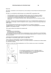
Wanneer de kogel , zonder aanhanger, de zichtbaarheid van de nummerplaat behindert,
dient men het afneembare deel van de trekhaak te demonteren.
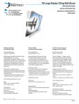
Haal de demper uit zijn ophangrubbers en verwijder de steunplaat.
Sla de bekleding van de kofferbak terug en plaats aan de binnenzijde van de
kokerbalken de platen “1” rechts en “2” links t.p.v. de openingen in de bodem.
Plaats de plaat “3” onder de rechter kokerbalk. Bevestig met bouten M8x35 de gaten “4”
en met bout M10x40 het gat “5” in de achterwand van het voertuig inclusief de platen “6”
(30x30mm) en “7” (20x20) zoals in het figuur is aangegeven.
Plaats de plaat “8” onder de rechter kokerbalk. Bevestig met bouten M8x35 de gaten “4”
en met bout M10x40 het gat “5” in de achterwand van het voertuig, inclusief de platen
“6” (30x30mm) en “7” (20x20) zoals in het figuur is aangegeven.
Boor met boor Ø 13mm in de bumpersteun t.p.v. de gaten “9”. Verwijder de boorschilfers
en bescherm het gat met roestwerende primer.
Monteer de dwarsbalk van de trekhaak “10” t.p.v. de gaten “11” met bouten M12x30 en
t.p.v. de gaten “9” met bouten M12x65.
Draai alle bouten en moeren aan . Monteer de stekkerdoos op de stekkerplaat en de
kogel m.b.v. de bouten M10x80. Sluit de bedrading aan volgens de bijgevoegde
handleiding en het instructieboekje van het voertuig. Tenslotte de uitlaatdemper met zijn
steun opnieuw monteren en bevestigen met bijgeleverde bout M8x25. Leg de bekleding
van de kofferbak terug.
•
•
•
•
•
•
•
4342 / 25.10.2004 / 3
GEBRUIK EN ONDERHOUD
1. Men dient het kogeldeel schoon en ingevet te bewaren. De diameter van de kogelkop (50mm)
dient men regelmatig te controleren. Zodra de diameter op een willekeurige plaats is
verminderd tot 49 mm mag men het kogeldeel om veiligheidsredenen niet meer gebruiken.
2. Afneembare systemen dient men te controleren op een spelingvrije verbinding van kogel
met systeem. Draag zorg voor het schoonhouden en smeren van beide.
3. Het is aan the bevelen om na ca. 1000 Km gebruik de boutverbindingen overeenkomstig de
tabel na te trekken.
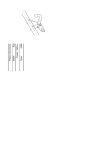
Demonteer de bumper. Plaats de boormal in het midden aan de onderzijde van de
bumper en zaag het aangegeven deel uit.
•
MONTAGEHANDLEIDING:
Indien t.p.v. de bevestigingspunten een bitumen laag of anti-dreunlaag aanwezig is, dient men
deze te verwijderen. Kaal plaatwerk en boor-gaten dient men van een roestwerende primer te
voorzien.
5.
OPMERKINGEN:
1. Voor montage dient men te controleren of de te monteren trekhaak, voor het voertuig de
juiste is.
2. Om veiligheidsredenen mag de trekhaak alleen door vakkundig personeel gemonteerd
worden.
3. Beschadigde onderdelen mogen alleen vervangen worden door originele onderdelen,
gemonteerd door vakkundig personeel.
4. Aan de trekhaak mogen geen veranderingen plaatsvinden
Trekhaak type:
Voertuig type:
Towing bracket type:
For cars:
4342
LANCIA MUSA / FIAT IDEA
GB
SAFETY INSTRUCTIONS:
1. Make sure the towbar is suitable for the vehicle before starting the installation activity.
2. For safety, all work involving tow-bar installation (including electrical components) must
be undertaken by skilled technicians.
3. Damaged components must be replaced with manufacturer’s spares and fitted by
qualified staff.
In absence of the trailer, if the towball limits the view of the numberplate, remove the
detachable part of the towbar.
4. It is forbidden to make any modification or structural repair to towing assembly.
5.
•
•
•
•
•
•
•
Attach the cross tube “10” to holes “11” with M12x30 bolts and to holes “9” with M12x50
bolts.
Drill with Ø 13mm flat drill the bumper support bolt with reference to holes “9”. Discard
the drilling burs and recoat the hole with rust proof paint.
Position the side-arm “8” under the left side-member. Attach it on holes “4” with M8x35
bolts and on hole “5” on the vehicle rear panel with M10x40 bolts, using the spreader
plates “6” (30x30mm) and “7” (20x20mm) as shown in the picture.
Position the side-arm “3” under the right side-member. Attach it on holes “4” with M8x35
bolts and on hole “5” on the vehicle rear panel with M10x40 bolts, using the spreader
plates “6” (30x30mm) and “7” (20x20mm) as shown in the picture.
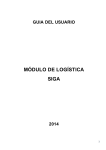
Lift the internal boot lining and position the spreader plates “1” on the right and “2” on the
left inside the side-members, using the hole on the floor.
Lower the silencer from its elastic supports and remove the support.
Remove the rear bumper and cut out a central aperture on the lower edge of the bumper,
using template and instructions supplied, to allow clearance for the ball supports.
FITTING INSTRUCTIONS:
Remove and scrape all underseal from areas which may come in contact with tow-bar assembly
and recoat areas with rust proof paint.
•
Torque all bolts to recommended values, fit the electrical sockets and the ball housing,
using the M12x65 bolts. Complete all electrical connections following the instructions
enclosed with wiring kits and guidelines outlined in vehicle handbook. Finally fit the
silencer by fixing its own support with the M8x25 screw supplied, and replace the boot
lining.
USE AND MAINTENANCE
1. Tow-bars should be kept clean and lubricated. For added safety, diameter of tow-ball (50mm)
should be checked at regular intervals. If tow-ball measures less than 49 mm, after selected
readings across diameter, tow-ball must be replaced with new system.
2. In case of detachable devices, check the absence of backlash between the tow-ball and
the connection device and provide for cleaning and lubrication of them.
3. After 1000 Km of towing, check torque settings for nuts and bolts, in accordance with table:
- (below).
4342 / 25.10.2004 / 4
USO E MANUTENZIONE
1. Mantenere la sfera dell’organo di traino pulita e lubrificata. Per motivi di sicurezza, controllare
periodicamente il diametro della sfera; qualora si riscontrasse un diametro di 49mm dopo
ripetute misurazioni in diversi punti della sfera, l’organo di traino non potrà più essere
utilizzato fino a sostituzione avvenuta della predetta sfera.
2. Nel caso di dispositivi smontabili, controllare la mancanza di giochi tra gli accoppiamenti sfera - dispositivo di attacco e provvedere alla pulizia ed alla lubrificazione degli
stessi.
3. Verificare il perfetto serraggio di tutte le viti dopo circa 1000 km di traino.
Larghezza max. rimorchiabile per Caravan e T.A.T.S.: 2,40 m
(Larghezza motrice +70cm = .... Arrotondare ai 5cm superiori)
(vedi D.M. 28/05/85) - (Circolare D.C. IV n.B100).
4342
LANCIA MUSA / FIAT IDEA
350????? ?? opp. 350????? ??? opp.
350????? ????
•
Massa max. rimorchiabile: vedere CARTA di CIRCOLAZIONE del veicolo
Dispositivo di traino tipo:
Per autoveicoli:
Tipo:
•
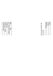
DA COMPILARE PER IL COLLAUDO
DICHIARAZIONE DI CORRETTO MONTAGGIO
Si Ditta dichiara di aver montato in maniera corretta ed in conformità alle prescrizioni sia
del costruttore del veicolo che del costruttore del dispositivo stesso il seguente dispositivo
di attacco meccanico:
tipo:.........................................................costruttore:........................................................
Il dispositivo di attacco meccanico sopra descritto è stato installato su autoveicolo
tipo:.........................................................targa:.................................................................
TIMBRO E FIRMA
Si dichiara inoltre di aver informato l’utente del veicolo sull’USO e MANUTENZIONE
del dispositivo stesso.
Data...............................................................
4342 / 25.10.2004 / 13
4342
LANCIA MUSA / FIAT IDEA
I
In assenza del rimorchio, nel caso la sfera limiti la visibilità della targa, smontare la parte
estraibile del dispositivo di traino.
Sganciare il silenziatore dai propri supporti elestici e rimuovere la staffa di supporto.
Alzare il rivestimento interno del vano bagagli e posizionare all’interno delle longherine
le contropiastre “1” a destra e “2” a sinistra utilizzando le asole esistenti sul pavimento.
Posizionare il tirante “3” sotto la longherina destra. Fissarlo con viti M8x35 nei fori “4”, e
con vite M10x40 nel foro “5” esistente sulla parete posteriore vettura, interponendo le
contropiastre “6” (30x30mm) e “7” (20x20mm) come indicato in figura.
Posizionare il tirante “8” sotto la longherina sinistra. Fissarlo con viti M8x35 nei fori “4” e
con vite M10x40 nel foro “5” esistente sulla parete posteriore vettura, interponendo le
contropiastre “6” (30x30mm) e “7” (20x20mm) come indicato in figura.
Forare con punta Ø13mm la staffa supporto paraurti con riferimento ai fori “9”. Eliminare
le bave di foratura e proteggere il foro effettuato con vernice antiruggine
Montare la traversa del dispositivo di traino “10” facendo riferimento ai fori “11” con viti
M12x30 e “9” con viti M12x50.
Serrare a fondo la bulloneria; montare la presa di corrente ed il blocchetto della sfera
utilizzando le viti M12x65. Effettuare i collegamenti elettrici seguendo le istruzioni allegate alla confezione del cablaggio elettrico e le istruzioni riportate sul libretto d’uso e
manutenzione della vettura; per ultimo rimontare il silenziatore fissando il proprio supporto con la vite in dotazione M8x25 e risistemare il rivestimento interno del vano bagaglio.
•
•
•
•
•
•
•
4342 / 25.10.2004 / 12
Smontare il paraurti posteriore e praticarvi, in posizione centrale inferiore, utilizzando
l’apposita maschera di foratura e seguendo le istruzioni in essa contenute, un taglio atto
al passaggio dei supporti sfera.
•
ISTRUZIONI DI MONTAGGIO:
Rimuovere gli eventuali mastici di protezione nelle zone di contatto fra scocca del veicolo e
dispositivo di traino; ed eventualmente verniciare le parti scoperte con vernice antiruggine.
5.
NOTE INFORMATIVE:
1. Prima di iniziare qualsiasi attività di installazione assicurarsi che l’organo di traino in oggetto
sia adatto per il veicolo sul quale lo si intende installare. Per eventuali chiarimenti chiamare
il: (Tel.n°0522/834213 - 0522/834206).
2. L’organo di traino è un elemento di sicurezza e come tale deve essere installato soltanto da
personale specializzato.
3. Eventuali pezzi danneggiati o usurati devono essere sostituiti con ricambi originali da
personale specializzato.
4. E’ proibito effettuare qualsiasi modifica sostanziale o riparazione strutturale sull’organo di
traino.
Istruzioni da conservare in fase di collaudo
Dispositivo di traino tipo:
Per autoveicoli:
4342
LANCIA MUSA / FIAT IDEA
D
4342 / 25.10.2004 / 5
Falls die Kugel (ohne Anhänger) die Kennzeichen-Sichtbarkeit beeinträchtigt, ist
der abnehmbare Teil der Zugvorrichtung abzumontieren.
MONTAGEANLEITUNG:
Die in den Berührungspunkten zwischen Fahrzeugaufau und Kupplungskugel eventuell
vorhandene Schutzdichtmasse entfernen und evt. die ungedeckten Teilen mit
Rostschutzfarbe anstreichen.
• Die hintere Stossstange abbauen und im mittleren und unteren Bereich mit Hilfe der
mitgelieferten Bohrschablone und der dazugehörenden Montageanleitungen, eine Öffnung durchführen, die zum Durchgang des Kugelshalterungs geeignet ist.
• Den Auspufftopf von seinen federnden Halterungen ausklinken und den Halterungsbügel fortschaffen.
• Die Kofferauminnenverkleidung anheben; und innen des Längsträgers die Gegenplatte
„1“ auf die Rechte Seite und die Gegenplatte „2“ auf die linke Seite positionieren und die
Ösen vom Boden benutzen.
• Die Zugstange „3“ unten die rechte Längsträger positionieren. Mit den Schrauben M8x35
die Bohrungen „4“ fixieren und mit den Schrauben M10x40 die Bohrung „5“ am Ruckseite des Fahrzeugs fixieren, wobei die Gegenplatte „6“ (30x30mm) und „7“ (20x20mm)
dazwischenzulegen sind – wie im Bild angezogen.
• Die Zugstange „8“ unten die linke Längsträger positionieren. Mit den Schrauben M8x35
die Bohrungen „4“ fixieren und mit den Schrauben M10x40 die Bohrung „5“ am Ruckseite des Fahrzeugs fixieren, wobei die Gegenplatte „6“ (30x30mm) und „7“ (20x20mm)
dazwischenzulegen sind – wie im Bild angezogen.
• Den Bügel der Stosstangeshalterung mit Bohrer Ø 13 mm bezüglich der Bohrungen „9“ durchbohren. Die Bohrgräten beseitigen, und die Bohrung mit Rostschutzfarbe anstreichen.
• Die Kupplungstraverse „10“ bezüglich der Bohrungen „11“ mit Schrauben M12x30 und
„9“ mit Schrauben M12x50 montieren.
• Schrauben und Muttern fest anziehen; die Steckdose und die Kugelhalterung mit Schrauben M12x65 montieren. Die elektrischen Anschlüsse herstellen. Zuletzt den Schalldämpfer wieder montieren, indem die eigene Halterung mit der mitgelieferten Schraube M8x25
zu befestigen ist, und die Kofferraum-Innerverkleidung wieder in Ordnung bringen.
GEBRAUCH UND WARTUNG
1. Die Kupplungskugel ist sauber und eingeschmiert zu halten. Aus Sicherheitsgruenden
ist der Kugeldurchmesser regelmaessig nachzupruefen. Sollte sich dabei nach
wiederholten Messungen an verschiedenen Kupplungsteilen ein Durchmesser von 49
mm herausstellen, dann darf die abgenutzte Kupplungskugel nicht mehr verwendet
werden, bis die oben genannte Kugel ersetzt worden ist.
2. Im Fall gibt es abnehmbare Einheiten, die Abwesenheit der Spielräume zwischen den
Kugelskupplungen und der Verbindungsvorrichtung nachprüfen und für die Säuberung
und die Schmierung sorgen.
3. Der vollkommene Zug saemtlicher Schrauben ist nach 1000 Km Ziehen wieder
nachzupruefen.
5.
INFORMATIVE ERKLAERUNGEN:
1. Bevor jegliche Einbaueingriffe vorgenommen werden, ist sicherzustellen, daß die betreffende
Kupplungskugel für das Fahrzeug geeignet ist, an welchem sie einzubauen ist.
2. Die Kupplungskugel ist ein Sicherheitsorgan und als solches nur durch Fachleute
einzubauen.
3. Eventuell beschaedigte bzw. abgenutzte Teile sind nur mit Original-Ersatzteilen durch
Fachleute zu ersetzen.
4. Keine wesentliche Abaenderung bzw. Konstruktionsreparatur an der
Anhaengevorrichtung vornehmen.
Kupplungskugel Typ:
für Fahrzeuge:
Dispositif de remorquage type:
Pour autos:
4342
LANCIA MUSA / FIAT IDEA
F
En absence de la remorque, si la boule limite la visibilité de la plaque, démonter la partie
démon table de l’attelage.
NOTES D’INFORMATION:
1. Avant de commencer l’activité d’installation s’assurer que l’attelage en objet va avec le
véhicule sur lequel il doit être installé.
2. L’attelage est un élément de sécurité et donc il peut être installé seulement par du personnel
qualifié.
3. Il faut que le personnel spécialisé remplace les éventuelles parties endommagées par des
pièces de rechange originales.
4. Il est interdit d’effectuer toutes les modifications substantielles et les réparations structurales
sur l’attelage.
5.
•
•
•
•
•
•
•
Monter la traverse de l’attelage “10” dans les trous “11” avec les vis M12x30 et “9” avec
les vis M12x50.
Percer avec mèche Ø13mm l’étrier de support dans les trous “9”. Ôter les bavures de
perçage et protéger le trou avec vernis antirouille.
Placer le tirant “8” sous le longeron gauche. Solidariser avec les vis M8x35 dans les
trous “4” et avec les vis M10x40 dans le trou “5” sur la partie arrière véhicule, en utilisant
les contreplaques “6” (30x30mm) et “7” (20x20mm) comme indiqué dans l’illustration.
Placer le tirant “3” sous le longeron droit. Solidariser avec les vis M8x35 dans les trous
“4” et avec les vis M10x40 dans le trou “5” placé sur la partie arrière véhicule, en utilisant
les contreplaques “6” (30x30mm) et “7” (20x20mm) comme indiqué dans l’illustration.
Soulever le revêtement intérieur de la malle et placer à l’interieur des longerons les
contreplaques “1” à droite et “2” à gauche, en utilisant les trous sur le sol.
Démonter le silencieux de son supports élastiques et démonter l’étrier de support.
Démonter le pare-chocs arrière et percer en position centrale inférieure, en utilisant le
gabarit de perçage et les instructions jointes, un trou pour le passage des supports
boule.
INSTRUCTIONS DE MONTAGE:
Enlever les éventuels mastics de protection dans les points de contact entre la coque de la
voiture et l’attelage, éventuellement vernir les parties découvertes avec du vernis antirouille.
•
Bloquer la boulonnerie, monter la prise de courant et le logement de la boule avec les
vis M12x65. Effectuer les connexions en suivant les instructions jointes à la boîte des
câbles pour le câblage et celles indiquées dans la notice d’entretien. A’ la fin remonter
le silencieux en fixant son support avec la vis livré M8x25 et replacer le revêtement
intérieur de la malle.
USAGE ET ENTRETIEN
1. Il faut maintenir la boule de l’attelage propre et lubrifiée. Pour des raisons de sécurité, contrôler
périodiquement le diametrè de la boule; si on relève un diamètre de 49 mm. après plusieurs
mesurages dans de différents points de la boule l’attelage ne pourra plus être utilisé jusqu’au
replacement de la boule susdite.
2. Dans le cas de dispositif amovible, vérifier líabsence de jeu entre les accouplements boule
etl’attelage et pourvoir au nettoyage et à la lubrification.
3. Vérifier le parfait serrage de toutes les vis après avoir parcouru 1000 Km. de traînage
environ.
4342 / 25.10.2004 / 6
Gancho de remolque:
Para autovehículos:
4342
LANCIA MUSA / FIAT IDEA
E
Si la bola (sin el remolque) cubre parcialmente o totalmente la matrícula, retirar la
partedesmontable del gancho de remolque.
NOTAS INFORMATIVAS:
1. Antes de empezar cualquier actividad de instalación asegurarse que el gancho de
remolquesea él apropiado para el vehículo al que se le quiere instalar.
2. El gancho de remolque es un elemento de seguridad y como tal debe ser instalado
solamentepor personal especializado.
3. Las partes que eventualmente puedan estar rotas o dañados deberán ser sustituidas
porrecambio original por personal especializado.
4. Esta prohibido efectuar cualquier modificación provisional o reparaciones estructurales
sobreel gancho de remolque.
5.
INSTRUCIONES DE MONTAJE:
Sacar la resina de protección sobre la zona de contacto entre la estructura del vehículo y
el enganche; y eventualmente barnizar la parte descubierta con barniz anti-oxido.
• Desmontar el parachoque posterior y practicar, en posición central inferior, utilizando la
misma mascara para taladrar y siguiendo las instruccines en el contenido, un corte
igual al pasar los soportes esfera.
• Desganchar el silenciador del proprio soporte elastico y quitar la estafeta de relevo de
los soportes.
• Levantar el suelo del maletero, y posicionar al interno de los largueros la contrachapa
“1” del lado derecho y “2” y el lado izquierdo utilizando los ojales esistente en el piso.
• Posicionar el tirante “3” debajo de los largueros del lado derecho. Fijarlo con tornillos
M8x35 y los huecos “4” y con tornillos M10x40 el hueco “5” ya existente en la pared
posterior del coche, interponiendo la contrachapa “6” (30x30mm) y “7” (20x20) como es
indicado en la figura.
• Posicionar el tirante “8” debajo de los largueros del lado izquierdo. Fijarlo con tornillos
M8x35 y los huecos “4” y con tornillos M10x40 el hueco “5” ya existente en la pared
posterior del coche, interponiendo la contrachapa “6” (30x30mm) y “7” (20x20) como es
indicado en la figura.
• Taladrar con punta Ø13mm el ojal de soporte parachoque con referimiento a los huecos
“9”. Eliminar el resto de lo taladrado y proteger el hueco hecho con barníz anti-oxido.
• Montar la travesía del gancho de remolque “10” haciendo referimiento a los huecos “11”
con tornilos M12x30 y “9” con tornillos M12x50.
• Cerrar a fondo los tornillos; montar la presa de corriente y la plaqueta de la esfera,
utilizando los tornillos M12x65 . Efectuar los colegamiento electríco, siguiendo las
instrucciones legada en la confeccione de los cables electrícos y las instrucciones que
son en el librito de uso y mantenimiento del vehículo; por último montar nuevamente el
silenciador, fijando con el propio soporte con los tornillos en dotación M8x25 y sistemar
denuevo el revestimiento interno del fondo de el baúl .
4342 / 25.10.2004 / 11
USO Y MANUTENCIÓN
1. Mantener la esfera del O.T. limpia y lubrificada. Por motivo de seguridad, controlar
periodicamente el diametro de la esfera; en el caso si se encuentra un diametro de 49
mm despuesde repetidas medidas en diversos puntos de la esfera, O.T. no podra ser
más utilizado hasta La sostitución de La misma predicha esfera.
2. En caso de dispositivos desmontables, controlar que no haya juego entre los
acoplamientos bola-dispositivo de enganche y proveer a la limpiadura y lubricación de
los mismos.
3. Verificar La perfecta cerradura de todos los Tornillos despues cerca 1000 Km de acareo.
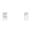
Cod.:
Vehicle:
4342
LANCIA MUSA / FIAT IDEA
1
3
2
4
4342 / 25.10.2004 / 9