1
www.benza.es
Modelo
Modêlo
Model
Motor
Motor
Engine
Alternador
Alternador
Alternator
Chasis
Chassis
Chassis
ES 4200CD
EX21
ER series
ES 4200CD
GENERADORES - GERADORES - GENERATORS
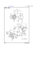
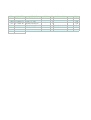
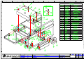
DESPIECE
PEÇAS
SPARE PAR TS
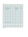
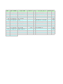
EX210 SPEC.No
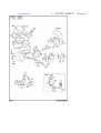
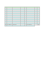
1 CRANK CASE
EX210DS5222
REF.
10
20
26
30
40
50
60
70
75
80
90
210
220
230
250
260
270
280
300
610
620
630
631
680
690
700
710
960
PART NUMBER PART NAME CODE NO.
278-10102-4CRANK CASE
237-14202-0VALVE GUIDE
277-16010-0STEM SEAL
044-02502-0OIL SEAL
060-02800-2BALL BEARIN
277-15011-0PIPE KNOCK
010-50802-5STUD
010-50603-5STUD
044-00600-2OIL SEAL
040-11400-3PLUG
021-11400-2GASKET
277-11002-2MAIN BEARIN
044-02502- OIL SEAL
060-02501-4BALL BEARIN
277-45004-JGOVERNOR GE
277-41901-0GOVERNOR SL
277-63601- OIL GAUGE
021-31600-2GASKET
001-04083-5FLANGE BOLT
278-13001- CYLINDER HE
277-15001-2GASKET(HEAD
011-00802-4FLANGE BOLT
011-00803- FLANGE BOLT
277-15503-0ROCKER COVE
277-16001- GASKET(ROCK
277-15011-0PIPE KNOCK
011-00600-2FLANGE BOLT
277-99001-2GASKET SET
QTY
R E M A R K INTERCHANGE
1 W/OIL SENSOR
2 5.5DX9.5DX27L
1 5.5DX9.5DX15DX7.8B
1 25DX38DX7B
1 28DX58DX16B
2 10.3DX8.5DX14L
2 M8X1.25X25L
2 M6X1.0X98L
1 6DX10DX2.5B
1 M14X1.5X20DX12L
1 14.1DX19DX2.3T
1 FLANGE 4-5/16-24UNF
1 25DX41.25DX6B
1 25DX52DX15B
1 53DX29.1T N=33
1 6DX7.6DX16DX26L
2 M18X1.5 L=70+18
2 16DX23DX1.2T RUBBER
6
1
1 T=0.2
4 M8X1.25X16DX68L
1 M8X1.25X16DX33L
1
1 T=0.5
2 10.3DX8.5DX14L
4 M6X1.0X14DX12L
1
FIG.
100
100
100
100
100
100
100
100
100
100
100
100
100
100
100
100
100
100
100
100
100
100
100
100
100
100
100
100
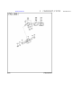
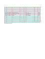
EX210 SPEC.No
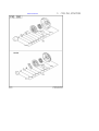
2 CRANKSHAFT,PISTON
EX210DS5222
REF.
10
50
70
310
311
320
350
360
361
362
370
371
372
380
PART NUMBER
278-21201-31
018-01400-20
032-30300-10
278-22501-10
278-22502-00
277-23001-03
277-23301-13
277-23401-J3
277-23403-J3
277-23404-J3
277-23501-17
277-23502-17
277-23503-17
056-51600-10
PART NAME
CRANKSHAFT CP
FLANGE NUT
WOODRUFF KEY
CONNECTING ROD AY
CONNECTING ROD AY
CONNECTING ROD BOLT
PISTON PIN
PISTON
PISTON
PISTON
PISTON RING SET
PISTON RING SET
PISTON RING SET
CLIP
INTERCHANGE FIG.
CODE NO. QTY
R E M A R K S
1 L=271 DH 19.2DX1/5.3
200
1 M14X1.5X28DX12H
200
1 3BX6HX16D
200
1 91.3CDX25B 30D-16D
200
1 0.25 U.S.
200
2 M6X1.0X13DX33L
200
1 16DX11DX48.5L
200
1 STD (67DX40H)
200
1 0.25 O.S.(67DX40H)
200
1 0.50 O.S.(67DX40H)
200
1 STD(67D) OIL 3 PIECE
200
1 0.25 O.S. OIL 3 PIEC
200
1 0.50 O.S. OIL 3 PIEC
200
2 17.1DX1.4D
200
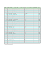
EX210 SPEC.No
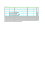
3
INTAKE EXHAUST
EX210DS5222
REF.
10
25
27
34
35
37
38
60
70
80
90
95
150
160
163
166
170
200
202
220
225
230
231
240
241
290
310
320
340
350
360
361
365
385
387
540
550
560
570
580
PART NUMBER
277-31601-31
277-35101-03
024-00600-10
277-38601-03
277-36401-03
277-36501-03
277-38702-03
279-33601-03
269-33701-03
277-33401-H3
277-33501-H3
132-10KA0-31
278-35601-11
277-36911-03
277-37101-03
277-36902-03
277-36913-13
277-35002-01
003-13050-00
277-36201-00
277-36202-00
014-90500-20
014-90500-20
017-00500-30
017-00500-30
011-00600-20
277-30101-J1
277-30101-H1
277-34201-21
277-34201-11
277-35201-13
980-20082-80
015-20600-90
011-00600-10
011-00803-20
277-37203-H1
015-00400-60
277-32902-J1
277-35903-J3
277-35902-J3
002-38060-00
011-00600-50
PART NAME
CAM SHAFT CP
PIN(CAM SHAFT)
O RING
PIN(SPRING)
RELEASE LEVER
CLIP
RETURN SPRING
VALVE SPRING
SPRING RETAINER
INTAKE VALVE
EXHAUST VALVE
COLLET-VALVE
TIMING CHAIN CP
TENTIONER
SPRING(TENTIONER)
PIN(TENTIONER)
CHAIN GUIDE
PIN(ROCKER) CP
CLIP
ROCKER ARM(IN) AY
ROCKER ARM(EX) AY
ADJUST SCREW
ADJUST SCREW
NUT
NUT
FLANGE BOLT
MUFFLER CP
MUFFLER CP
MUFFLER COVER CP
MUFFLER COVER CP
GASKET(MUFFLER)
FLANGE NUT
TAPPING BOLT
FLANGE BOLT
FLANGE BOLT
SCREEN CP
TAPPING SCREW
INSULATOR CP
GASKET2(INSULATOR)
GASKET1(INSULATOR)
FLANGE NUT
FLANGE BOLT
CODE NO. QTY
R E M A R K S NTERCHANG FIG.
1 85DX2.9B N=40
300
1 9DX78.5L
300
1 5.8DX9.6D
300
1 4DX8DX9L
300
1
300
1 13.8DX20.3DX0.4T
300
1 5.1DX0.6DX4.4L N=7
300
2 19.2DX2.3DX27.4L
300
2
300
1 25.5DX5.5DX68.1L
300
1 23.5DX5.5DX68.1L
300
4
300
1 92 LINK
300
1
300
1 10DX1.8DX14L N=4.5
300
1 6DX13DX34L
300
1
300
1 6DX46L
300
1
300
1
300
1
300
1 M5X0.5X23L
300
1 M5X0.5X23L
300
1 M5X0.5X4.1H
300
1 M5X0.5X4.1H
300
1 M6X1.0X14DX12L
300
70001
300
-6999
1
300
70311
300
-7030
1
300
1 T=0.2 26D 9DX58P
300
2
300
2 M6X13DX10L
300
1 M6X1.0X14DX8L
300
1 M8X1.25X16DX12L
300
1
300
2 M4X6L
300
1
300
1 T=0.5
300
1 T=0.5
300
2
300
1 M6X1.0X13DX20L
300
EX210 SPEC.No
3
INTAKE EXHAUST
EX210DS5222
REF.
510
-200
-210
-220
-250
-260
-270
-272
-520
PART NUMBER
277-32615-20
277-32615-10
277-32630-18
277-32610-08
277-32604-08
277-32640-08
277-32609-08
277-32741-18
277-32741-08
277-32607-08
277-32611-07
PART NAME
CODE NO. QTY
R E M A R K S TERCHANG FIG.
AIR CLEANER AY 70921
315
AIR CLEANER AY
-7091
1 DUAL
315
BASE CP
1
315
PACKING
1
315
PACKING
1
315
COVER CP
1
315
LABEL
1
315
WING NUT
70921
315
WING NUT
-7091
1
315
WING NUT
1
315
ELEMENT SET
1 DUAL
315
EX210 SPEC.No
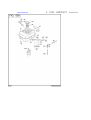
4 GOVERNOR,OPERATION
EX210DS5222
REF.
10
20
30
40
50
60
70
80
310
340
350
355
360
365
435
450
485
PART NUMBER
277-42301-23
277-42201-33
277-42701-11
277-42801-23
003-13050-00
013-00602-40
018-60600-20
279-42505-33
277-43303-03
277-43502-03
277-44501-03
021-70600-70
004-31062-50
237-45004-23
277-46002-02
002-35060-00
011-00600-20
PART NAME
GOVERNOR LEVER
GOVERNOR SHAFT
GOVERNOR ROD CP
ROD SPRING
CLIP
BOLT AND WASHER AY
NUT
GOVERNOR SPRING
SPEED CONTROL LEVER
STOP PLATE
WASHER
FRICTION WASHER
SCREW
SPRING (ADJUST)
SPEED CONT.BRKT UN
SELF LOCK NUT
FLANGE BOLT
CODE NO. QTY
R E M A R K S TERCHANG FIG.
1
400
1
400
1
400
1 7DX0.5DX182L N=16
400
1
400
1 M6X1.0X25L W/TWO W
400
1 M6X1.0X4.9H SQUARE
400
1 7.5DX0.7DX115L N=25
400
1
400
1
400
1
400
1 6.5DX24DX0.8T NYLON
400
1
400
1 6.9DX0.9DX20L N=7
400
1
400
1
400
2 M6X1.0X14DX12L
400
EX210 SPEC.No
5 COOLING,STARTING
EX210DS5222
REF.
10
20
40
41
60
61
62
81
82
110
135
220
PART NUMBER
278-51251-01
073-20054-70
011-00600-30
011-00600-10
277-52712-03
277-52702-03
278-52701-03
011-00600-20
015-20500-10
278-54101-03
277-75501-03
011-00600-10
PART NAME
BLOWER HOUSING CP
LABEL(TRADE MARK)
FLANGE BOLT
FLANGE BOLT
BAFFLE 1(CASE)
BAFFLE 2(HEAD)
BAFFLE 3
FLANGE BOLT
TAPPING SCREW
COOLING BLOWER
CLAMP(SEL)
FLANGE BOLT
CODE NO. QTY
R E M A R K S
1 DS ROBIN YELLOW
1 60D
4 M6X1.0X14DX14L
1 M6X1.0X14DX8L
1
1
1
1 M6X1.0X14DX12L
2 M5X10DX10L
1
1
4 M6X1.0X14DX8L
INTERCHANGE
FIG.
500
500
500
500
500
500
500
500
500
500
500
500
EX210 SPEC.No
5 COOLING,STARTING
EX210DS5222
REF.
210
- 1
- 2
- 3
- 4
- 5
- 6
- 7
- 8
- 11
- 49
PART NUMBER
278-50201-20
270-50115-08
269-50120-08
282-50111-18
261-50100-08
270-50125-08
227-50131-08
227-50135-08
270-50261-08
278-50145-08
227-50152-08
PART NAME
RECOIL STARTER AY
SPIRAL SPRING
REEL
STARTER ROPE
STARTER KNOB
RATCHET
FRICTION SPRING
RETURN SPRING
RATCHET GUIDE
STARTER PULLEY
SET SCREW
CODE NO. QTY
R E M A R K S TERCHANG FIG.
1 160PD
520
1
520
1
520
1
520
1
520
2
520
1
520
2
520
1
520
1
520
1
520
EX210 SPEC.No
6
FUEL LUBRICANT
EX210DS5222
REF.
10
20
23
30
40
48
60
63
70
90
PART NUMBER
277-60101-11
073-20051-81
278-95111-03
043-04400-50
X64-13600-10
050-51200-20
002-38060-00
011-00601-30
278-62601-01
056-11100-50
X56-11100-20
224 277-43801-01
PART NAME
CODE NO. QTY
R E M A R K S NTERCHANG FIG.
FUEL TANK CP
1 3.6L ROBIN YELLOW
600
LABEL(WARNING)
1 42X104 ENGLISH
600
LABEL(MODEL)
1 28X99
600
FUEL TANK CAP CP
1 43DX68DX14H BLACK
600
FUEL FILTER
1
600
UNION
1 M12X4DX78L W/FILTER
600
FLANGE NUT
2
600
FLANGE BOLT
1 M6X1.0X14DX25L
600
FUEL PIPE CP
1
600
HOSE CLAMP
69722
600
HOSE CLAMP
-6971
2 10.5DX8BX0.7T
600
CHOKE LEVER CP
1
600
EX210 SPEC.No
6
FUEL LUBRICANT
EX210DS5222
REF.
210
- 1
- 2
- 3
- 5
- 8
- 11
- 12
- 14
- 15
- 16
- 17
- 18
- 19
- 20
- 22
- 24
- 28
- 40
- 41
- 44
- 45
- 62
- 79
-102
-144
-300
-302
-303
-325
-327
PART NUMBER
278-62302-30
277-62535-08
209-62351-08
277-62525-08
278-62420-08
277-62520-08
277-62531-18
227-62451-08
277-62500-08
277-62515-08
277-62506-08
214-62450-08
214-62540-08
226-62506-08
278-62440-08
277-62405-08
226-62701-18
277-62360-08
106-62556-08
283-62357-08
106-62411-08
106-62410-08
236-62680-08
236-62541-08
246-62390-08
277-62553-08
279-62103-10
277-62110-18
277-62100-18
277-62552-08
165-62377-08
PART NAME
CARBURETOR AY
THROTTLE VALVE
SCREW
CHOKE VALVE
PILOT JET
CHOKE LEVER
THROTTLE SHAFT-A
BOLT
NEEDLE
PIN
FLOAT BODY AY
PACKING
CHAMBER PACKING
FLOAT
MAIN NOZZLE
MAIN JET
CLIP
BOLT
SCREW
SPRING
AIR JET
AIR JET(PILOT)
SEAL
PACKING
SEAL
NUT
COCK BODY-A
PACKING
CUP
O-RING
SCREW
CODE NO. QTY
R E M A R K S INTERCHANGE
1
1 #160
1
1
1 #41.3
1
1
1
1
1
1
1
1
1
1
1 #83.8
1
1
1
1
1
1
1
1
1
1
1
1
1
1
2
FIG.
640
640
640
640
640
640
640
640
640
640
640
640
640
640
640
640
640
640
640
640
640
640
640
640
640
640
640
640
640
640
640
EX210 SPEC.No
7
ELECTRIC DEVICE
EX210DS5222
REF.
10
11
12
20
23
30
35
50
100
110
PART NUMBER
278-79251-01
277-79431-01
277-79301-01
277-71002-03
277-79501-03
001-14062-50
001-13063-50
279-73105-H1
065-01401-50
065-50002-70
PART NAME
FLYWHEEL CP
IGNITION COIL CP
LAMP COIL CP
RING GEAR
SPACER
BOLT AND WASHER AY
BOLT AND WASHER AY
WIRE 5 CP
SPARK PLUG
SPARK PLUG CAP
TERCHANG FIG.
CODE NO. QTY
R E M A R K S
1 MARK MF5368
700
1 MARK BM3790
700
1
700
1 D 159DX186DX6B N=105
700
1
700
2
700
2
700
1 L=510 BLACK
700
1 NGK BR6HS
700
1
700
EX210 SPEC.No
7
ELECTRIC DEVICE
EX210DS5222
REF.
128
130
131
220
- 1
230
384
PART NUMBER
980-40081-10
011-00604-70
011-00604-80
066-00003-30
066-00099-80
147-71401-01
056-30000-20
PART NAME
STR PIN-8X10
FLANGE BOLT
FLANGE BOLT
SWITCH
KEY,SWITCH
DIODE RECTIFIER CP
WIRE BAND
CODE NO. QTY
R E M A R K S TERCHANG
1
1 M6X1.0X13DX20L
1 M6X1.0X13DX30L
1
2 MARK 103
1
1 2.5BX1.2TX100L
FIG.
720
720
720
720
720
720
720
EX210 SPEC.No
7
ELECTRIC DEVICE
EX210DS5222
REF.
120
- 1
- 6
- 7
- 8
- 9
- 11
- 15
- 16
- 17
- 19
- 20
- 32
- 33
- 43
- 44
- 46
- 49
- 73
PART NUMBER
277-70502-00
277-70550-08
277-70551-08
277-70520-08
227-70561-08
277-70501-08
277-70502-08
277-70573-08
227-70562-08
277-70570-08
254-70576-08
227-70573-08
277-70574-08
277-70560-08
227-70574-08
227-70572-08
277-70571-08
277-70572-08
227-70577-08
PART NAME
STARTING MOTOR AY
YOKE ASSY
ARMATURE ASSY
CLUTCH,SUB-ASSY
NUT,PINION STOP
HOUSING ASSY
FLAME ASSY
CONTACTOR ASSY
RING,SNAP
BOLT,THROUGH
NUT
WASHER,PLATE SK
SCREW,W/WASHER
SPRING
COLLAR,ARMATURE
O RING
O RING
WIRE,SUB-ASSY
BOLT,W/WASHER
CODE NO. QTY R E M A R K S INTERCHANGE
1
1
1
1
1
1
1
1
1
2
2
1
1
1
1
2
2
1
1
FIG.
730
730
730
730
730
730
730
730
730
730
730
730
730
730
730
730
730
730
730
EX210 SPEC.No
7
ELECTRIC DEVICE
EX210DS5222
REF.
700
705
733
740
741
PART NUMBER
277-76301-21
KU3-11043-11
277-75801-03
013-00602-60
015-20500-10
PART NAME
OIL SENSOR CP
FLOAT C/U CP3
SHIELD PLATE(O/S)
BOLT AND WASHER AY
TAPPING SCREW
CODE NO. QTY
R E M A R K S NTERCHANGE FIG.
1
770
1
770
1
770
2 M6X1.0X16L W/SW
770
1 M5X10DX10L
770
EX210 SPEC.No
9 ACCESSORIES LABEL
EX210DS5222
REF. PART NUMBER
PART NAME
10 277-90301-H0 ACCESSORY TOOL KIT
CODE NO. QTY
1
R E M A R K S
INTERCHANGE
FIG.
900
serie ER
MANUALE D'USO E MANUTENZIONE
USE AND MAINTENANCE MANUAL
MANUEL POURL'EMPLOI ET L`ENTRETIEN
BEDIENUNGS - UND WARTUNGANLEITUNG
MANUAL PARA EL USO Y MANTENIMIENTO
INFORMAZIONI GENERALI
GENERAL INFORMATION
INFORMATIONS GENERALES
Le presenti istruzioni hanno lo scopo dindicare le corrette condizioni dimpiego e manutenzione dei generatori SINCRO.
The object of these instructions is to indicate correct operating - maintenance
conditions.
Le présent mode demploi a pour objet de
donner les informations nécessaires à un
emploi et à un entretien correct des
générateurs SINCRO.
VERIFICHE PRELIMINARI
Si raccomanda di esaminare lalternatore
per verificare che non abbia subito danni
durante il trasporto.
PRELIMINARY CHECKS
We recommend inspecting the alternator
after shipping for damage.
VERIFICATIONS PRELIMINAIRES
Contrôler létat de lalternateur afin de relever
les dommages éventuels subis durant le
transport.
IMMAGAZZINAGGIO
In caso di inutilizzo prolungato, lalternatore
deve essere immagazzinato in luogo asciutto
e coperto.
Prima della messa in servizio, dopo lunghi
periodi di inattività, controllare la bontà disolamento di tutti gli avvolgimenti; valori accettabili devono essere maggiori di 2 MW.
In caso contrario si deve procedere
allessiccazione del solo alternatore in forno (60÷80°C).
STORAGE
In case the alternator is not installed
immediately, it should be kept indoors in a
dry place.
Before starting the alternator, after a long
period of inactivity or storage, the insulation
resistance of the winding must be measured.
An acceptable value is at least 2 MW.
If this is not reached, only the alternator
must be dried in an oven at 60 ÷ 80 C°.
INSTALLAZIONE
Prima della messa in funzione, verificare la
bontà dei collegamenti, e lassenza dimpedimenti alla rotazione del rotore.
Fare attenzione che le aperture per laspirazione e espulsione dellaria non siano ostruite, evitare inoltre che lalternatore aspiri
laria calda espulsa dallalternatore stesso
e/o dal motore.
INSTALLATION
Before starting we recommended checking
the connections and make sure that there is
no obstacle to the rotation of the rotor.
Make sure that the air inlet and outlet are
free from obstacles.
Prevent the alternator from sucking the
warm air from the motor or itself.
STOCKAGE
En cas de non-utilisation prolongée de
lalternateur, ce dernier doit être stocké
dans un lieu sec et à labri des agents
atmosphériques. Après une période de
non-utilisation prolongée, la mise en service
doit être précédée par un contrôle de
lisolement de tous les enroulements. Les
valeurs acceptables doivent être supérieures
à 2MW. Si tel nest pas le cas, procéder à la
dessiccation de lalternateur dans un four
(60÷80°C).
COLLEGAMENTO ELETTRICO
Rispettare le norme di sicurezza vigenti del
paese dutilizzo.
Verificare che i dati di targa siano conformi
alle caratteristiche dellimpianto a cui la
macchina verrà collegata.
Provvedere al collegamento a terra del gruppo.
ELECTRIC CONNECTION
The electric connection must be performed
in accordance with the local regulations in
force. Make sure that the rating plate data
correspond to the specifications of the power
mains to which the machine will be
connected. Provide the unit with adequate
grounding.
MANUTENZIONE
Verificare che non ci siano anomalie, come
vibrazioni - rumori - uscite daria ostruite.
MAINTENANCE
Check periodically if there are any anomalies
such as vibrations - noise - obstructions of
inlets and outlets.
!
!
INSTALLATION
Avant la mise en service, vérifier la qualité
des connexions et quil nexiste aucun
empêchement à la rotation du rotor.
Sassurer que les ouvertures pour la
ventilation ne sont pas obstruées. Eviter
que lalternateur aspire ses propres
émanations dair chaud ou celles émises
par le moteur.
CONNEXION ELECTRIQUE
Respecter les normes de sécurité en vigueur
dans le pays dinstallation. Vérifier la
conformité des données de plaque aux
caractéristiques de linstallation à laquelle
la machine sera branchée. Effectuer la
liaison du groupe avec la borne de terre.
ENTRETIEN
Vérifier périodiquement le bon fonctionnement du groupe afin de relever
déventuelles anomalies comme, vibrations
- bruits suspects - obstruction des sorties
dair.
!
ATTENZIONE!
Non toccare l'alternatore durante il funzionamento e subito dopo l'arresto del gruppo,
in quanto vi potrebbero essere superfici a
temperatura elevata
WARNING!
Never touch the alternator during operation
or immediately after the stopping of the unit
because some surface parts might still be
very hot.
ATTENTION!
Ne pas toucher lalternateur lors de son
fonctionnement et tout de suite après larrêt
du groupe à cause dun risque de
température élevée des surfaces.
Le macchine elettriche rotanti sono macchine che presentano parti pericolose in quanto poste sotto tensione o dotate di movimento durante il funzionamento, pertanto:
- un uso improprio
- la rimozione delle protezioni e lo scollegamento dei dispositivi di protezione
- la carenza di ispezioni e manutenzione
possono causare gravi danni a persone o
cose.
Di conseguenza per ogni operazione di
carattere elettrico o meccanico si richiede
personale qualificato.
Electric rotating machines have dangerous
parts: when operating they have live and
rotating components. Therefore:
- improper use
- the removal of protective covers and the
disconnection of protection devices
- inadequate inspection and maintenance
can cause personal injury or property
damage.
Electrical and mechanical servicing must
be performed by qualified personnel only.
Les machines électriques rotatives
présentent des parties dangereuses car
elles sont sous tension ou dotées de
mouvement. Cest pourquoi:
-Une utilisation non conforme,
-La violation des protections et le
débranchement de ces dernières,
-Un manquement dans les contrôles et
lentretien,
peuvent causer de graves dommages aux
personnes et aux matériels.
Toutes les opérations à caractère électrique
ou mécanique demandent donc lintervention
de personnel qualifié.
ALLGEMEINE INFORMATIONEN
INFORMACIONES GENERALES
Diese Anleitung dient zur richtigen
Verwendung und Wartung der SINCRO
Generatoren.
Este manual ha sido recopilado con el
objetivo de suministrar al usuario todas las
indicaciones necesarias sobre el correcto
empleo y mantenimiento de los alternadores
SINCRO.
VORPRÜFUNG
Es wird empfohlen, sich zu überzeugen,
daß der Generator keinen Versandschaden
erlitten hat.
LAGERUNG
Wenn man für eine lange Zeit den Generator
nicht verwendet, soll er auf einer trockenen
Stelle gelagert werden. Vor der
Inbertriebsetzung ist es besser, die
Isolierung aller Wicklungen zu prüfen; nur
ein über 2 MW liegender Wert ist akzeptabel,
sonst ist das Trocknen des Generators im
Ofen (60÷80°C) erforderlich.
INSTALLATION
Vor der Inbetriebnahme, sind die Anschlüsse
auf ihre guten Zustand zu prüfen, der Rotor
soll hindernisfrei rotieren können. Sich
überzeugen, daß die Öffnungen für die
Luftanssaugung und den Luftauslaß nicht
verstopft sind.
Es ist zu vermeiden, daß der
Wechselstromgenerator die vom Generator
selbst bzw. vom Motor ausgestoßene
Warmluft ansaugt.
ANSCHLUSS
Für den Anschluß die landesgültigen
Unfallschutzvorschriften einhalten.
Sich überzeugen, daß die Daten des
Schildes den Eigenschaften der Anlage
entsprechen, an die die Maschine
angeschlossen wird.
Für den Erdungsanschluß des Aggregats
vorsehen.
WARTUNG
Es ist wichtig, daß keine Schwingungen,
Geräusche, verstopfte Luftauslässe
vorhanden sind.
!
ACHTUNG
Den Generator während des Betriebs und
gleich nach dem Anhalten des Aggregats
nicht anfassen, da die Flächen heiß sein
könnten.
Elektrische Rotationmaschinen weisen
gefährliche Teile auf, die entweder unter
Spannung stehen oder während des
Maschinenbetriebs drehen.
Daher können:
- unsachgemäßer Gebrauch;
- Entfernen der Schutzverkleidungen und
Überbrücken oder Abklemmen der
Schutzeinrichtungen
- mangelhafte Inspektion oder Wartung
zu schweren Personen- oder Sachschäden
führen.
Daher soll jeder elektrische oder
mechanische Eingriff von Fachpersonal
vorgenommen werden.
VERIFICACIÓN PRELIMINÁR
Aconsejamos comprobar que el alternador
no haya sufrido daños durante el transporte.
ALMACENAJE
En caso de largos períodos de inactividad,
hay que almacenar el alternador en un lugar
seco y cubierto.
Antes de la puesta en marcha, después de
un período largo de inactividad, controlar el
aislamiento de todos los bobinados, valores
aceptables tienen que ser mayores de los
2MW. En caso contrario hay que secar sólo
el alternador en horno (60÷80°C).
INSTALACIÒN
Antes de la puesta en marcha verificar el
estado de las conexiones y comprobar que
no hay nada que pueda impedir la rotaciòn
del rotor.
Controlàr que los orifìcios de aspiraciónexpulsión del aire no están obstruidos,
además evitar que el alternador aspire aire
caliente evacuado por el mismo alternador
y/o por el motor.
CONEXIÓN ELÉCTRICA
Respetar las normas de seguridad vigentes
en el país de utilización.
Verificar que los datos de placa
corresponden a las características de la red
en el lugar de instalación de la máquina.
Efectuar la puesta a tierra del grupo.
MANTENIMIENTO
Comprobar que no hay anomalías como
vibraciones, ruidos y salidas de aire
obstruidas.
!
ATENCIÓN
Nunca tocar el alternador durante el
funcionamiento o inmediatamente después
de la parada del grupo, dado que hay
superficies de temperatura elevada
Las màquinas eléctricas giratorias son
máquinas que tienen piezas peligrosas ya
que están bajo tensión o se mueven durante
el funcionamiento. Por lo tanto:
- el uso inadecuado
- la remoción de las protecciones y la
desconexión de los dispositivos de
seguridad
- la falta de chequeo y mantenimiento,
pueden causar danõs graves a personas o
cosas.
Por consiguiente, las operaciones de
carácter eléctrico o mecánico deben llevarse
a cabo únicamente por personas
cualificadas.
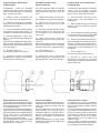
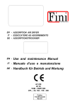
ISTRUZIONI PER IL MONTAGGIO
(FORMA IM B35)
ASSEMBLY INSTRUCTIONS
(IM B35 COUPLING)
INSTRUCTIONS POUR LE MONTAGE
(FORME IM B35)
ATTENZIONE:
prima del montaggio
verificare che le sedi coniche di accoppiamento (sia dell'alternatore che del motore)
siano regolari e ben pulite.
ON: before assembly make sure that the
conical coupling housings for both the
alternator and the motor are in order and
clean.
ATTENTION: Avant deffectuer le montage,
vérifier que les sièges coniques
daccouplement (de lalternateur comme du
moteur) sont en ordre et bien nettoyés.
1) Fissare lo scudo copriventola (3) al
motore (dopo averlo tolto dall'alternatore).
1) Clamp the fan shield (3) on the drive
motor (after removing it from the alternator).
2) Applicare il tirante (6) per il fissaggio
assiale del rotore avvitandolo sulla sporgenza dell'albero motore.
2) Apply the tie rod (6) for the axial
clamping of the rotor, and screw it on the
drive shaft.
1) Fixer le bouclier couvre-rotor (3) au
moteur (après lavoir désolidarisé de
lalternateur).
3) Fissare l'alternatore completo (statore
e rotore assieme) allo scudo usando i 4
tiranti M8 (17) e i dadi autobloccanti M8 (D)
3) Fasten the complete alternator (stator
and rotor together) to its shield, using the
4 tie rods M8 (17) and the M8 (D) selflocking nuts.
4) Bloccare assialmente il rotore avvitando il dado autobloccante M8 (D) sul
tirante (6).
Attenzione: prima di applicare il dado osservare che parte della porzione filettata del
tirante entri nel rotore permettendo cosí un
sicuro bloccaggio.
4) Axially lock the rotor in place by
tightening the M8 (D) self-locking nut on the
tie rod (6).
Caution: before applying the nut, make sure
that the threaded part of the rod partially
enters the rotor in order to obtain tight locking.
5) Montare il tappo (13).
Fissare le due griglie di protezione (1).
5) Fasten the tap (13).
Fasten the protection grid (1).
6) Supportare il gruppo con adeguati
antivibranti (A) curando il corretto allineamento tra motore e alternatore
6) Support the unit on appropriate
vibration dampeners (A) taking care on the
alignment between engine and alternator.
REGOLAZIONE DELLA VELOCITA
La frequenza e la tensione dipendono direttamente dalla velocità di rotazione, la quale
deve quindi rimanere il più possibile costante al variare del carico.
Considerando che il sistema di regolazione
della velocità dei motori di trascinamento
presenta in generale una leggera caduta di
giri tra vuoto e carico, si raccomanda di
regolare la velocità a vuoto circa il 3÷4%
superiore alla velocità nominale.
Con questa regolazione la tensione erogata
dallalternatore a vuoto risulta circa il 5%
superiore al valore nominale.
SPEED ADJUSTMENT
Frequency and voltage depend directly on
the speed of revolution, which must therefore
remain as constant as possible when the
load varies.
The speed adjustment system of the drive
motors usually gives a slight drop in
revolutions between no load and load, so
when the no load speed is being adjusted, it
is best to set it at approx. 3-4% above the
rated speed.
With this adjustment the no load voltage
supplied by the alternator will be about 5%
over its rated value.
2) Mettre en place la tige (6) de fixation
axiale du rotor en la vissant à lergot de
larbre moteur.
3) Fixer lalternateur (complet avec stator
et rotor) au bouclier au moyen de 4 tiges M8
(17) et les écrous autobloquants M8 (D).
4) Bloquer laxe du rotor en serrant lécrou
autobloquant M8 (D) sur la tige centrale (6).
Attention: Avant de mettre en place lécrou,
contrôler que la partie filetée de la tige est
insérée dans le rotor permettant ainsi un
blocage sûr.
5) Fixer le bouchon (13).
Fixer lex deux grilles de protection (1).
6) Soutenir le groupe avec des
amortisseur de vibrations (A) en faisant
attention que le moteur et l'alternateur soient
dans le même axe.
RÉGLAGE DE LA VITESSE
La fréquence et la tension dépendent
directement de la vitesse de rotation qui doit
rester le plus possible constante quand la
charge varie.
Vu que le système de réglage de la vitesse
des moteurs dentraînement présente en
général une légère baisse du nombre de
tours à vide ou en charge, il est conseillé de
régler la vitesse à vide à une valeur
supérieure de 3 à 4 % par rapport à la
vitesse nominale.
Avec ce réglage, la tension générée par
lalternateur à vide est supérieure denviron
5 % par rapport à la vitesse nominale.
MONTAGEANLEITUNG
(IMB35 ANSCHLUSS)
INSTRUCCIONES DE MONTAJE
(ACOPLAMIENTO IMB35)
ACHTUNG: Sich vor dem Einbau überzeugen, daß die kegelförmigen Kupplungssitze (sowohl des Generators als auch des
Motors) regelmässig und sauber ist.
AVISO: Antes del montaje cerciorarse de
que los asientos cónicos de acoplamiento
(tanto del alternador como del motor) son
regulares y limpios.
1) Das Flügelrad-Abdeckschild (3) am
Motor befestigen (nachdem es vom
Generator entfernt wurde).
1) Fijar el escudo cubreventilador (3) al
motor (después de haberlo sacado del
alternador).
2) Die Spannstange (6) für die Längsbefestigung des Rotors anbringen und sie
auf der Vorkragung der Motorwelle
festschrauben.
2) Aplicar el tirante (6) para la fijación
axial del rotor enroscándolo en la parte
saliente del eje motor.
3) Den vollständigen Generator (Stator
und Rotor zusammen) mit den 4 Spannstangen M8 (17) und den selbstsperrenden
M8 Muttern (D) am Kasten befestigen.
4) Den Rotor axial blockieren, und die
selbstsperrende M8 Mutter (D) an die
Spannstange (6) anzuschrauben.
Achtung: bevor die Mutter angebracht wird,
beatchten, dass ein Teil des Gewindes der
Spannstange in den Rotor eintritt und
dadurch eine sichere Blockierung
ermöglicht.
5) Den Stopfen (13) montieren.
Den zwei Schutzgitter (1) montieren.
6) Das Aggregat mit geeigneten
Schwingungsdämpfern (A) stützen, dabei
die korrekte Ausrichtung zwischen Motor
und Generator beachten.
EINSTELLUNG DER GESCHWINDIGKEIT
Frequenz und Spannung hängen direkt von
der Drehgeschwindigkeit ab, die daher bei
Lastveränderung so konstant wie möglich
bleiben muss.
Unter Berücksichtigung, dass das
Regulierungssystem der Geschwindigkeit
der Mitnehmermotoren im allgemeinen
einen leichten Drehzahlabfall zwischen
Leerlauf und Last aufweist, wird empfohlen,
die Leerlaufgeschwindigkeit auf ca. 3÷4%
höher als die Nenngeschwindigkeit
einzustellen.
Mit dieser Regulierung wird die vom
Wechselstromgenerator bei Leerlauf
gelieferte Spannung ca. 5% höher als der
Nennwert sein.
3) Fijar el alternador completo (estator y
rotor juntos) en el escudo utilizando los 4
tirantes M8 (17) y las tuercas de seguridad
M8 (D).
4) Bloquear axialmente el rotor
enroscando la tuerca autobloqueante M8
(D) en el tirante (6).
Aviso: para realizar un bloqueo seguro,
antes de aplicar la tuerca hacer entrar una
parte de la pieza fileteada del tirante en el
rotor.
5) Montar el tapòn (13).
Fijar las dos rejillas de protecciòn (1)
6) Sostener el grupo con antivibradores
(A) adecuados cuitando de que el motor y el
alternador se encuentren correctamente
alineados.
REGULACION DE LA VELOCIDAD
Tanto la frecuencia como la tensión
dependen directamente de la velocidad de
rotación, lo que supone que ésta
permanecerá lo más posible constante al
variar la carga.
Dado que el sistema de regulación de la
velocidad de los motores de arrastre presenta una ligera disminución de revoluciones
entre vacío y cargado, se recomienda regular
la velocidad en vacío alrededor del 3÷4%
superior a la velocidad nominal.
De hacerlo así, la tensión suministrada por
el alternador en vacío resultará de casi el
5% superior al valor nominal.
Schemi elettrici
Wiring diagrams
Schema electrique
Schaltpläne
Esquemas eléctricos
Colori-colourscouleur-farbecolor
Bianco: white blanc
weiss blanco
Blu: blue bleu
blau azul
Grigio: grey gris
grau gris
Nero: black noire
schwarz negro
Marrone: brown
marron braun
marròn
Rosso: red rouge
rot rojo
Arancione: orange
orange orange
anaranjado
Giallo: yellow jaune
gelb amarillo
Viola: violet violette
violett violeta
COLORE (*) TENSIONE FREQUENZA
COLOR (*) VOLTAGE FREQUENCY
GRIGIO
GIALLO
ARANCIONE
VIOLA
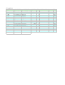
Resistenze degli
avvolgimenti a 20°C
Winding resistances
at 20°C
Résistances bobines
à 20°C
50 Hz - 3000 r.p.m. - 230V
Tipo
Type
Type
Typ
Tipo
Potenza
Power
Puissance
Leistung
Potencia
Statore
Stator
Stator
Stator
Estator
Ausiliario Carica batt.
Auxiliary Batt. charger
Excitation Char. Batt.
Erregung Ladegerät
Excitaciòn Carga baterìa
115V/230V
120V/240V
110V/220V
120V/240V
50 Hz
50 Hz
60 Hz
60 Hz
Widerstand der
Wicklung bei 20°C
Resistencias de los
bobinados a 20°
60 Hz - 3600 r.p.m. - 240V
Rotore
Rotor
Rotor
Rotor
Rotor
Condensat.
Capacitor
Condensat.
Kondensator.
Condensat.
Potenza
Power
Puissance
Leistung
Potencia
Statore
Stator
Stator
Stator
Estator
Ausiliario Carica batt.
Auxiliary Batt. charger
Excitation Char. Batt.
Erregung Ladegerät
Excitaciòn Carga baterìa
Rotore
Rotor
Rotor
Rotor
Rotor
Condensat.
Capacitor
Condensat.
Kondensator.
Condensat.
(R1)
(R2)
(R3)
(R4)
(450V)
(R1)
(R2)
(R3)
(R4)
(450V)
kVA
Ω
Ω
Ω
Ω
µF
kVA
Ω
Ω
Ω
Ω
µF
(56/
3.7
6.9
0.25
1.6
20
2.8
5.7
0.21
1.6
20
(56/
2.8
5.6
0.2
1.7
25
2.11
4.7
0.18
1.7
25
(56/
2.1
3.1
0.19
1.9
30
1.6
2.6
0.16
1.9
30
(5&/
1.23
2.4
0.15
2.1
36
0.93
2
0.13
2.1
36
Restituzione macchine in riparazione
Returning machines repaired
Retour marchandises pour reparation
Rückgabe der maschinen zur reparatur
Devolución máquinas en reparación
Lo scopo della presente scheda è assicurare al Cliente un
valido ed efficiente servizio di
assistenza. Questa scheda
dovrà essere consegnata all'utilizzatore finale da parte del
venditore locale.
PROCEDURA
Nel caso di guasti o anomalie
di funzionamento delle macchine Sincro, il Cliente è invitato ad interpellare il nostro
"Servizio Assistenza" telefonando al 0445-450500.
Se, dopo tale contatto, risultasse necessaria la restituzione del prodotto, il nostro
"Servizio Assistenza" fornirà
al Cliente un numero di "Rientro Materiale Autorizzato"
(RMA), che dovrà essere riportato sia sui documenti di
accompagnamento del materiale che nella presente Scheda di Riparazione.
Prodotti resi senza aver seguito la descritta procedura e
privi della scheda di riparazione, verranno respinti al mittente dal magazzino accettazione.
Per l'eventuale concessione
della garanzia è indispensabile che la Sincro sia contattata
esclusivamente dal proprio
Cliente. Richieste di riparazione provenienti direttamente dall'utilizzatore finale saranno in ogni caso considerate
NON in garanzia.
Prima di procedere a riparazioni verrà comunicato un preventivo e si attenderà l'autorizzazione da parte del Cliente
SCHEDA DI
RIPARAZIONE
La scheda di riparazione deve
essere compilata per ogni prodotto ed inclusa nell'imballo di
restituzione. L'accuratezza
nella compilazione renderà il
nostro intervento rapido e risolutivo.
SPEDIZIONE
La merce resa viaggia esclusivamente a spese e a rischio
del Cliente indipendentemente dalla concessione dell'intervento in garanzia.
Curare che le macchine siano
in ordine, pulite e che l'olio di
eventuali moltiplicatori di giri
sia stato vuotato.
Si raccomanda di restituire il
materiale entro un imballo adeguato curando di proteggere il
prodotto dagli urti.
The scope of this card is to
ensure the client with a valid
and efficient assistance
service. This card must be
given to the purchaser by the
local dealer.
PROCEDURE
Whenever any Sincro
machine malfunctions, the
client is invited to contact our
Assistance Service by
calling ++39 0445 450500. If
the decision is made to return
the product, we will provide
you with an Authorized
Material Return (RMA)
number that must be included
both in the delivery
documents that accompany
the material and this Repair
Card. Products that have
been returned without
following the procedure
above and without a Repair
Card will be returned to
sender.
In order to obtain coverage
under the warranty, Sincro
must
be
contacted
exclusively by its authorized
dealer. Requests for repairs
received directly from final
user clients will be considered
outside the terms of warranty
coverage. Prior to performing
repair, an estimate will be
provided and authorization
must be received from the
authorized dealer before
proceeding with the repair.
REPAIR CARD
A repair card must be
compiled for every product
and enclosed in the
packaged product sent for
repair. Providing accurate
and complete information in
the Repair Card will help us
repair the product faster and
better.
SHIPMENT
All products to be repaired
are shipped at the risk and
expense of the client
regardless of whether
warranty coverage will be
claimed or not. The client
must make sure that the
machines sent for repair are
in good order, clean, and that
the oil in the overgear system
has been drained. We
recommend returning the
products in adequate
packaging that ensures
protection against impact.
Le but de la présente fiche
est dassurer au client un
service après-vente rapide
et efficace. Cette fiche devra
être communiqué à lutilisateur final de la part du
revendeur agréé.
PROCEDURE
En cas de pannes ou
danomalies de fonctionnement des machines
Sincro, le client est invité à
contacter notre Service
Assistance en téléphonant
au ++39 0445 450500. Si à la
suite de ce contact, la
restitution du produit savère
nécessaire, notre Service
Assistance communiquera
au client un numéro pour le
Retour Matériel Autorisé
(RMA) qui devra être reporté
sur le document daccompagnement du matériel comme
sur la présente Fiche
technique de réparation.
Les produits rendus sans
avoir suivi la procédure
décrite et privés de la Fiche
technique de réparation
seront
retournés
à
lenvoyeur. Pour une
éventuelle concession de
garantie il est indispensable
que la Sincro soit contacté
directement par le revendeur
agréé. Les demandes de
réparation effectuées par
lutilisateur final seront
considérées comme étant
hors garantie. Toute
demande de réparation fera
lobjet dun devis.
FICHE TECHNIQUE DE
REPARATION
La fiche technique de
réparation doit être remplie
pour chacun des produits et
jointe à la marchandise
restituée. La clarté des
données fournies permettra
une intervention rapide et
décisive.
EXPEDITION
Les frais dexpédition sont à
la charge du client et cela,
indépendamment du fait que
la marchandise soit encore
sous garantie. Faire en sorte
que les machines soient au
complet, nettoyées et que
lhuile des éventuels
multiplicateurs de tours ait été
évacuée. Il est conseillé
dexpédier la machine dans
un emballage adapté et
antichoc.
Zweck dieser Karte ist, dem
Kunden einen guten und wirksamen Kundendienst zu gewährleisten. Diese Karte soll
dem Endbenutzer vom lokalen
Verkäufer übergeben werden.
Esta ficha se remite al Cliente
con la finalidad de garantizarle un servicio de postventa
válido y eficiente. El revendedor local tiene que suministrarla al usuario final.
VERFAHREN
Bei Schäden oder Betriebsstörungen der Sincro-Maschinen,
ist der Kunde gebeten, unseren
"Kundendienst" unter der Nummer ++39 0445 450500 anzurufen.
Falls nach dieser Kontaktaufnahme eine Rückgabe des Produkts erforderlich sein sollte,
gibt unser "Kundendienst" dem
Kunden eine "Nummer für die
Rückgabe von autorisiertem
Material" (RMA), die sowohl in
die Begleitunterlagen des Materials als auch in diese
Reparaturkarte einzutragen ist.
Produkte, die ohne o.g. Vorgang und ohne Reparaturkarte
zurückgegeben werden, werden nicht akzeptiert und von
der Annahmestelle an den Absender zurückgegeben.Für
eine eventuelle Garantiegewährung ist es erforderlich,
daß die Fa. Sincro ausschließlich vom Kunden selbst kontaktiert wird. Vom Endbenutzer
gemachte Reparaturanfragen
werden in jedem Fall als NICHT
unter Garantie stehende Fälle
bearbeitet.
Vor der Reparaturausführung
wird ein Kostenvoranschlag mitgeteilt und eine Genehmigung
seitens des Kunden abgewartet.
PROCEDIMIENTO
En caso de averías o anomalías de funcionamiento de las
máquinas Sincro, aconsejamos al Cliente que se ponga
en contacto con el Servicio
Postventa llamando el número ++39 0445 450500. Si a
continuación de la llamada
fuera necesario devolver el
producto, el Servicio de
Postventa suministrará al
Cliente un número de Regreso Material Autorizado
(RMA), que deberá encontrarse tanto en los documentos
de expedición del material,
como en la presente Ficha de
Reparación.
Productos devueltos sin haber efectuado el procedimiento descrito anteriormente y los
que no tengan la ficha de reparación, se rechazarán al
Cliente del Almacén de aceptación.
Por lo que respecta a la posible concesión de la garantía,
es preciso que Sincro se
contacte únicamente por el
Cliente; la petición de reparaciones directamente por parte del usuario final han de
considerarse NON en garantía. Antes de proceder a la
reparación se comunicará un
presupuesto al Cliente y se
esperará la autorización del
mismo.
REPARATURKARTE
Die Reparaturkarten müsen für
jedes Produkt ausgefüllt werden und in der Rückgabeverpackung eingeschlossen sein.
Die sorgfältige Ausfüllung ermöglich einen unserseitigen raschen und problemlösenden
Eingriff.
VERSAND
Unabhängig von der Gewährung des Garantieeingriffs, reist
die zurückgegebene Ware ausschließlich auf Kosten und Risiken des Kunden. Sich überzeugen, daß die Maschinen in Ordnung und sauber sind und daß
das Öl eventueller Drehzahlübersetzer ausgeleert wurde.
Es wird empfohlen, das Material
in
einer
entsprechend
geeigneten
Verpackung
zurückzugeben, um das
Produkt vor Stößen zu
schützen.
FICHA DE REPARACIÓN
La ficha de reparación debe
completarse para cada producto e incluirse en el embalaje de devolución. La esmerada completación de la ficha
permitirá una reparación rápida y eficiente.
ENVÍO
Los gastos de transporte corren por cuenta y riesgo del
Cliente, independientemente
de la concesión de la intervención en garantía.
Cerciorarse de que las máquinas están limpias y en buen
estado, y que el aceite de los
posibles multiplicadores de
vueltas ha sido vaciado. Aconsejamos devolver el material
en un embalaje que permita
protegerlo durante el transporte.
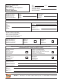
Scheda di riparazione:
Repair card:
Fiche technique de réparation:
Reparaturkarte:
Ficha de reparación:
Descrizione del prodotto:
Description of product:
Description du produit:
Produktbezeichnung:
Descripción del producto:
RMA:
DATA:
Tecnico contattato:
Technician contacted:
Technicien contacté:
Kontaktierter Techniker:
Técnico contactado:
Modello:
Model:
Modèle:
Modell:
Modelo:
Matricola:
Serial number:
N° de série:
Kennummer:
Matrícula:
Tel/Fax:
Ditta:
Company:
Entreprise:
Firma:
Empresa:
Persona da contattare:
Contact person:
Contact:
Ansprechpartner:
Persona a contactar:
Barrare la casella corrispondente:
Put an "X" in the corresponding box:
Barrer la case correspondante:
Das entsprechende Kästchen ankreuzen:
Rellenar la casilla correspondiente:
Motivo della restituzione:
Reason for return::
Motif(s) de la restitution:
Begründung d. Rückgabe:
Motivo de la devolución:
Riparazione:
Repair:
Réparation:
Reparatur:
Reparación:
Manutenzione:
Maintenance:
Entretien:
Wartung:
Mantenimiento:
IDENTIFICAZIONE CLIENTE - CLIENT IDENTIFICATION - DONNEES DIDENTIFICATION CLIENT KUNDENBEZEICHNUNG - IDENTIFICACIÓN DEL CLIENTE
Assenza di tensione:
No voltage:
Absence de tension:
Spannungsmangel:
Falta de tensión:
Problemi sul quadretto elettrico:
Electrical control panel problems:
Problème au niveau des circuits électriques:
Probleme am Schaltbrett:
Problemas en el cuadro eléctrico:
Tensione bassa:
Low voltage:
Tension insuffisante:
Niederspannung
Tensión baja:
Tensione alta:
High voltage:
Surtension:
Hochspannung:
Tensión alta:
Problemi meccanici:
Mechanical problems:
Problèmes mécaniques:
Mechanische Probleme:
Problemas mecánicos:
Note:
Notes:
Remarques:
Anmerkungen:
Notas:
SINCRO s.r.l. - Via Tezze, 3 - Loc. Cereda - 36073, Cornedo (Vi), Italy - Tel. 0445 450500 - Fax 0445 446222
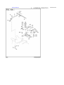
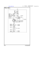
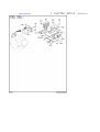
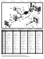
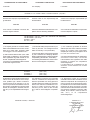
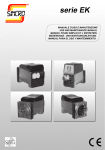
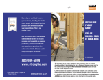
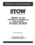
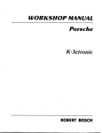
Disegno esploso
Exploded view
Vue eclatee
Teilmontagezeichnung
Despiece
3
4
8
9
7
10
2
1
5
18
7
6
17
11
16
15
14
12
3
19
13
Spare parts list
Parti di ricambio
N.RIF
CODICE
SINCRO
DESCRIZIONE
1 266062001
Griglia anteriore IP21
2 266042001
Griglia anteriore IP23
3(*) 4061011023 Scudo anteriore "E" IMB35 J609A
Pieces detachees
DESCRIPTION
Front grid IP21
Ersatzteilliste
DESCRIPTION
Grille de protection antérieure IP21
Partes de recambio
BESCHREIBUNG
Vorderes Gitter IP21
DESCRIPCIÓN
Rejilla anterior IP21
Front grid IP23
Grille de protection antérieure IP23
Vorderes Gitter IP23
Rejilla anterior IP23
Front shield "E" IMB35 J609A
Flasque antérieur "E" IMB35 J609A
Vorderer Kasten "E" IMB35 J609A
Escudo anterior "E" IMB35 J609A
4061011031 Scudo anteriore "E" IMB35 J609B
Front shield "E" IMB35 J609B
Flasque antérieur "E" IMB35 J609B
Vorderer Kasten "E" IMB35 J609b
Escudo anterior "E" IMB35 J609B
4061011022 Scudo anteriore "E" IMB35 c.23-c.30
Front shield "E" IMB35 c.23-c.30
Flasque antérieur "E" IMB35 c.23-c.30
Vorderer Kasten "E" IMB35 c.23-c.30
Escudo anterior "E" IMB35 c.23-c.30
4061011011 Scudo anteriore "E" IMB34 (B3/B14)
Front shield "E" IMB34 (B3/B14)
Flasque antérieur "E" IMB34 (B3/B14)
Vorderer Kasten "E" IMB34 (B3/B14)
Escudo anterior "E" IMB34 (B3/B14)
Lüfterrad mit Loch Ø 30
Ventilador agujero φ30
4(*) 266083001
Ventola (con foro φ30)
Fan (with hole φ30)
Ventilateur (avec trou φ30)
5(*) 521226…
Rotore ER (Accoppiamento ?) (1)
Rotor ER (Coupling ?) (1)
Rotor ER (Accouplement ?) (1)
Rotor ER (Kupplung ?) (1)
Rotor ER (Acoplamiento ?) (1)
6(*) 17600…
Tirante albero (dimensioni-accoppiam.?)
Shaft stay bolt (dimensions-coupling ?)
Tige centrale (dimensions-accouplem. ?)
Spannstange (Kupplungsabmessung ?)
Tirante àrbol (dimens. - acoplamiento ?)
7 1750016004 Cuscinetto 6004 C3
Bearing - 6004 C3
Roulement - 6004 C3
Lager 6004 C3
Cojinete 6004 C3
8 79060
Diodo + Varistore + Condensatore EMC
Diode + Varistor + EMC Capacitor
Diode + Varistor + Condensateur EMC
Diode + Varistor + Kondens.EMC
Diodo+Variador+Condensador EMC
9(*) 266014005
Coperchio ER rosso
ER red top cover
Couvercle supérieur ER rouge
Gitterhaltedeckel ER rot
Tapa roja (ER)
266024008
Coperchio ER nero
ER black top cover
Couvercle supérieur ER noir
Gitterhaltedeckel ERschwarz
Tapa negra (ER)
7065…
Quadretto ER (vedi...)
ER panel (see...)
Tableau ER (voir...)
Schaltbrett ER (siehe . . . )
Cuadro ER (Véase...)
Cuffia EK cieca
Blind EK end cover
Couvercle post. aspiration EK sans trous
EK Schutzkasten
Tapa EK ciega posterior
Cuadro EK monofasico (Véase...)
12(*) 266061004
7022…
13 266064007
14(*) 300100020
Quadretto EK monofase (vedi...)
EK single-phase panel (see...)
Tableau monophasè EK (voir...)
Schaltbrett EK einphasiger (siehe . . . )
Tappo EK
Tap (EK)
Bouchon (EK)
Stopfen EK
Tapòn EK
Condensatore 20 µF 450V
Capacitor 20 µF 450V
Condensateur 20 µF 450V
Kondensator 20 µF 450V
Condensator 20 µF 450V
300100025
Condensatore 25 µF 450V
Capacitor 25 µF 450V
Condensateur 25 µF 450V
Kondensator 25 µF 450V
Condensator 25 µF 450V
300100030
Condensatore 30 µF 450V
Capacitor 30 µF 450V
Condensateur 30 µF 450V
Kondensator 30 µF 450V
Condensator 30 µF 450V
Condensator 35 µF 450V
300100035
15 17900540
179005401
16(*) 661203…
Condensatore 35 µF 450V
Capacitor 35 µF 450V
Condensateur 35 µF 450V
Kondensator 35 µF 450V
Molla portacondensatore EK (φ 35-40)
EK (φ 35-40) capacitor block spring
Ressort fixation condens. EK(φ 35-40)
EK (φ 35-40) - Kondensatorhaltefeder
Resorte portacondensador EK (φ 35-40)
Molla portacondensatore EK (φ 45-50)
EK (φ 45-50) capacitor block spring
Ressort fixation condens. EK(φ 45-50)
EK (φ 45-50) - Kondensatorhaltefeder
Resorte portacondensador EK (φ 45-50)
Carcasa + Estat. ER
Carcassa + Stat. ER
Housing + Stat. ER
Carcasse + Stat. ER
Gehäuse + Stat. ER
17 176002030
Tirante M8x30
Stay bolt - M8x30
Tige M8x30
Spannstange M8x30
Tirante M8x30
19 300005
KIT: da IMB35 J609B a IMB34 (B3/B14)
KIT: from IMB35 J609B to IMB34 (B3/B14)
KIT: de IMB35 J609B à IMB34 (B3/B14)
KIT: von IMB35 J609B bis IMB34 (B3/B14)
KIT: da IMB35 J609B a IMB34 (B3/B14)
(1) Comprende il particolare 6
(1) 6 item is included
(1) Comprend la pièce 6
(1)Teil 6 inbegriffen
(1) Incluye el particular 6
(*) Includere nella richiesta di pezzi di ricambio la descrizione dell'oggetto, il codice, il numero di matricola e le caratteristiche della macchina (rilevabili dalla targhetta).
(*) When ordering spare parts, please indicate the alternator code-number and machine serial number and characteristics (they are available on the label)
(*) Nous vous prions d’indiquer, dans vos commandes de pièces de rechange, la description de la pièce, le numéro de code et de série et les caractéristiques de la machine
(*) In den Ersatzteilanfrage sind die Gegenstandbeschreibung, die Materialnummer, die Kennummer und die Eigenschaften der Maschine (vom Schild zu entnehmen) anzugeben.
(*) Solicitar las piezas de recambio siempre indicando la descripción del objeto, el código, el número de matrícula y las características de la máquina (descritas en la placa de identificación).
,1&219(1,(17,
&$86(
5,0(',2
Il generatore non si eccita.
1) Macchina smagnetizzata.
1) Applicare ai morsetti d’uscita per 1 sec. una
2) Velocità ridotta.
2) Controllare i giri e portarli al valore nominale.
tensione continua compresa tra 6 ÷12 V.
3) Diodi rotanti difettosi.
3) Controllare e sostituire.
4) Condensatore difettoso
4) Controllare e sostituire.
5) Guasto negli avvolgimenti.
5) Controllare le resistenze degli avvolgimenti come da
1) Velocità ridotta.
1) Controllare i giri e regolare.
2) Diodi rotanti difettosi.
2) Controllare e sostituire.
tabella.
Tensione a vuoto bassa.
3) Condensatore di valore errato
3) Controllare e sostituire.
4) Avvolgimenti avariati.
4) Controllare le resistenze degli avvolgimenti come da
1) Velocità motore troppo alta.
1) Controllare i giri e regolare.
alta.
2) Condensatore di valore errato
2) Controllare e sostituire.
Tensione corretta a vuoto,
1) Possibile sovraccarico.
1) Controllare la corrente di carico.
troppo bassa a carico.
2) Il motore rallenta.
2) Controllare dimensionamento motore.
3) Diodi rotanti difettosi.
3) Controllare e sostituire.
Tensione instabile.
1) Contatti incerti.
1) Controllare le connessioni.
2) Irregolarità di rotazione.
2) Verificare l’uniformità di rotazione.
1) Aperture di ventilazione
1) Smontare e pulire le cuffie di aspirazione ed
tabella.
Tensione a vuoto troppo
Surriscaldamento della
macchina.
parzialmente ostruite.
espulsione aria.
2) Possibile sovraccarico.
2) Controllare la corrente di carico.
1) Cuscinetti avariati.
1) Controllare e sostituire.
2) Accoppiamento difettoso.
2) Verificare e riparare.
'()(&7
&$86(
5(0('<
The alternator does not excite.
1) Demagnetized machine.
1) Apply to the terminal a DC voltage between 6÷12V
2) Reduced speed.
2) Check the speed and bring it to the rated value.
3) Faulty rotating diodes.
3) Check and replace.
4) Faulty rotating diodes.
4) Check and replace.
Macchina rumorosa.
for 1 second.
Low no-load voltage
5) Failure in the windings.
5) Check the windings resistances as per the table.
1) Reduced speed.
1) Check the speed and regulate.
2) Faulty rotating diodes.
2) Check and replace.
3) Wrong capacitor value.
3) Check and replace.
4) Faulty windings.
4) Check the resistance as per the table.
Too high no-load voltage
1) Excessive motor speed.
1) Regulate the motor speed.
2) Wrong capacitor value.
2) Check and replace.
Correct no-load voltage
1) Probable overload.
1) Check the load current.
and too low full-load
2) The engine speed slows down.
2) Check motor dimensions.
voltage.
3) Faulty rectifier bridge.
3) Check and replace.
Unstable voltage.
1) Loose connections.
1) Check the connections.
Machine overheating.
2) Irregular rotation.
2) Verify the rotation uniformity.
1) Partially obstructed ventilation
1) Remove and clean the air inlet and outlet grids.
openings.
Noisy machine.
2) Probable overload.
2) Check the load current.
1) Faulty bearings.
1) Check and replace.
2) Faulty coupling.
2) Verify and repair.
3$11(6
&$86(6
62/87,216
Le générateur ne s’excite pas.
1) Machine démagnétisée.
1) Appliquer aux bornes en sortie durant 1 seconde
2) Vitesse réduite.
2) Contrôler les tours et les porter à la valeur nominale.
3) Diodes roulantes défectueuses.
3) Contrôler et substituer si nécessaire.
une tension continue comprise entre 6 ÷ 12V.
4) Condensateur défectueux.
4) Contrôler et substituer si nécessaire.
5) Pannes au niveau des bobines.
5) Contrôler les résistances des bobines en suivant les
1) Vitesse réduite.
1) Contrôler les tours et les régler si nécessaire.
indications données par le tableau.
Tension à vide insuffisante.
2) Diodes roulantes défectueuses.
2) Contrôler et substituer si nécessaire.
3) Valeur du condensateur erronée.
3) Contrôler et substituer si nécessaire.
4) Bobines défectueuses.
4) Contrôler les résistances des bobines en suivant les
Tension à vide trop élevée.
1) Vitesse moteur trop élevée.
1) Contrôler les tours et les régler si nécessaire.
2) Valeur du condensateur erronée.
2) Contrôler et substituer si nécessaire.
Tension à vide correcte.
1) Possible surcharge.
1) Contrôler le courant de charge.
Tension en charge insuffisante.
2) Le moteur ralenti.
2) Contrôler dimensions moteur.
indications données par le tableau.
3) Diodes roulantes défectueuses.
3) Contrôler et substituer si nécessaire.
Tension instable.
1) Contacts incertains.
1) Contrôler les connexions.
2) Irrégularité dans la rotation.
2) Vérifier l’uniformité de la rotation.
Surchauffe de la machine.
1) Ouvertures ventilation
1) Démonter et nettoyer les protecteurs aspiration et
partiellement obstruées.
expulsion air.
2) Possible surcharge.
2) Contrôler le courant de charge.
1) Coussinets endommagés.
1) Contrôler et substituer si nécessaire.
2) Accouplement défectueux.
2) Contrôler et réparer.
67g581*
856$&+(
$%+,/)(
Der Generator erregt sich nicht.
1) Entmagnetisierung der Maschine.
1) En den klemmen für eine Sekunde eine
2) Antriebsdrehzahl zu niedrig.
2) Drehzahl des Antriebsmotors auf Nennwert bringen.
3) Fehlerhafte drehende Diode.
3) Kontrollieren und ersetzen.
4) Fehlerhafter Kondensator
4) Wicklungswiderstände entsprechend der Tabelle
5) Wicklungensstörung.
5) Kontrollieren und ersetzen.
1) Antriebsdrehzahl zuniedrig.
1) Drehzahl kontrollieren und regeln.
Niveau sonore machine élevé.
Gleichspannung zwischen 6 und 12 V anbringen
überprüfen.
Niedrige Leerlaufspannung.
2) Fehlerhafte drehende Diode.
2) Kontrollieren und ersetzen.
3) Wicklungen beschädigt.
3) Wicklungswiderstände entsprechend der Tabelle
4) Kondensator mit falschen Wert
4) Kontrollieren und ersetzen
1) Antriebsdrehzahl zu hoch.
1) Drehzahl kontrollieren und regeln.
überprüfen.
Zu hohe Leerlaufspannung.
4) Kondensator mit falschen Wert
4) Kontrollieren und ersetzen
Richtige Leerlaufspannung,
1) Zu hohe Belastung.
1) Belastungsstrom überprüfen.
Lastspannung zu gering.
2) Zu geringe Antriebsleistung.
2) Abgabeleistung des Motors überprüfen.
3) Fehlerhafte drehende Dioden
3) Kontrollieren und ersetzen.
Spannungsschwankungen.
1) Fehlerhafte Kontakte.
1) Elektrische Anschlüsse überprüfen.
2) Drehzahlschwankungen.
2) Drehzahlregler des Antriebsmotors einstellen.
Zu stärke Erwärmung der
1) Lüftungsgitter verstopft.
1) Zu-und Abluftgitter demontieren und reinigen.
Maschine.
2) Zu hohe Belastung.
2) Belastungsstrom überprüfen.
Geräuschentwicklung.
1) Schadhafte Kugellager.
1) Uberprüfen und ersetzen.
2) Fehlerhafte Verbindung von
2) Uberprüfen und reparieren.
Motor u. Generator.
)$//$
&$86$
62/8&,Ï1
El alternador no se excita.
1) Máquina desmagnetizada.
1) Aplicar a los terminales de salida durante 1 segundo
2) Velocidad reducida.
2) Comprobar las RPM del motor y llevarlas a su valor
3) Diodos rotatorios defectuosos.
3) Comprobar y sustituir.
una tensión continua de entre 6-12 V.
nominal .
4) Condensador defectuoso
4) Comprobar y sustituir
5) Avería en los bobinados.
5) Comprobar las resistencias de los bobinados, como
1) Velocidad reducida.
1) Comprobar las RPM y regular.
2) Diodos rotatorios defectuosos.
2) Comprobar y sustituir.
se indica en la tabla.
Tensión en vacio baja.
3) Condensador de valor incorrecto
3) Comprobar y sustituir
4) Avería en los bobinados.
4) Comprobar las resistencias de los bobinados, como
se indica en la tabla.
Tensión en vacio demasiado alta. 1) Velocidad del motor demasiado alta. 1) Comprobar las RPM y regular.
2) Entrehierro del compound alto.
2) Regularlo.
Tensión correcta en vacío,
1) Posible sobrecarga.
1) Comprobar la corriente de carga.
demasiado baja en carga.
2) El motor decelera.
2) Comprobar el dimensionamiento del motor.
3) Diodos rotatorios defectuosos.
3) Comprobar y sustituir.
1) Contactos inciertos.
1) Controlar las conexiones.
Tensión inestable.
Sobrecalentamiento de la
máquina.
Ruido en la máquina.
2) Irregularidad de rotación.
2) Verificar la uniformidad de rotación.
1) Orificios de ventilación
1) Desmontar y limpiar las envolturas de aspiración y
parcialmente obstruidos.
expulsión aire.
2) Posible sobrecarga.
2) Comprobar la corriente de carga.
1) Cojinetes defectuosos.
1) Comprobar y sustituir.
2) Acoplamiento defectuoso.
2) Comprobar y arreglar.
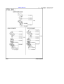
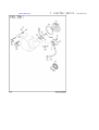
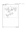
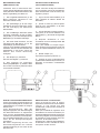
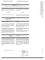
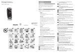
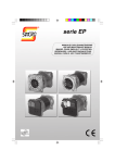
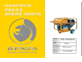
Verifica dei diodi.
Con un ohmmetro controllare ogni singolo diodo che dovrà indicare continuità in un solo senso.
Oppure con una pila e una lampadina invertendo la polarità della pila la lampadina si deve accendere in un solo senso come da figura.
Checking the diodes.
Use an ohmmeter to check each individual diode. Diodes must show continuity in one direction only.
This check can also be done using a battery and a light bulb. When inverting battery polarity, the light
bulb must turn on and off, in one direction only, as shown in the figure below.
Contrôle des diodes.
A laide dun ohmmètre, contrôler les diodes une à une. Chacune delle devra indiquer continuité en
sens unique.
Ce test peut être réalisé avec une pile et une ampoule. En inversant les pôles de la pile, lampoule
doit sallumer dans le seul sens indiqué sur la figure.
Überprüfung des Gleichrichters (Dioden).
Die Dioden werden mit einem Widerstandsmessgerät (Ohmmeter) geprüft.
Die Dioden müssen in einer Richtung sperren und in der anderen durchlassen. Die Messung kann
auch mit einer Glühlampe und einer Hilfsspannüng (Batterie) durchgeführt werden. Die Lampe muss
in einer Stromrichtung aufleuchten und in der anderen dunkel bleiben (siehe Figur).
Verificaciòn de los diodos.
Con un ohmniómetro comprobar cada diodo que deberá indicar continuidad en un sólo sentido. O
bien, con una pila y una bombilla, invirtiendo la polaridad de la pila, la bombilla tiene que encenderse
solo en un sentido, tal como se indica en la figura.
CONFORMITY CERTIFICATE
DICHIARAZIONE DI CONFORMITA'
The company
La società
DECLARATION DE CONFORMITE'
La société
SINCRO s.r.l.
Via Tezze,3 - Loc. Cereda - 36073 - Cornedo Vicentino - (Vi) ITALY
dichiara sotto la propria responsabilità che
gli alternatori
declares under its own responsibility that
the alternators:
déclare sous sa propre responsabilité que
les alternateurs
serie ER
serie ER
série ER
sono costruiti e collaudati in accordo alle
norme di seguito indicate:
have been manufactured and tested in compliance with the following standards
sont construits et testés dans le respect des
normes indiquées ci-après:
CEI EN 60034-1 (CEI 2-3 - NF 51.100 - VDE 0530 - BS 4999-5000)
CEI EN 60204-1 (CEI 44-5)
EN 292-1, 292-2
IEC 34.1, 34.5
e risultano conformi:
and thereby conform to:
et sont conformes:
1) ai requisiti generali di sicurezza stabiliti
dalla Direttiva Bassa Tensione del 19 Febbraio 1973 (73/23 CEE), recepita in Italia
con la legge n°791 del 18 Ottobre 1977.
1) all General Safety Requirements as provided by the EEC Low Voltage Directive
dated 19 February 1973 (73/23 EEC).
1) Aux conditions générales de sécurité
établies par la Directive relative à la basse
tension du 19 Février 1973 (73/23 CEE),
adoptée par lItalie par promulgation de la
loi n°791 du 18 Octobre 1977.
2) alla Direttiva 89/336 CEE (mod. dalla
93/68 CEE) riguardante il ravvicinamento
delle legislazioni degli stati membri in materia di compatibilità elettromagnetica.
La verifica di compatibilità è stata condotta
in base alle seguenti norme:
2) all principal safety requirement specified
by the Committee for Adapting Member
States Legal Regulation on Electromagnetic
Compatibility (89/336 EEC, 93/68 EEC).
The following standards were used to evaluate the electromagnetic compatibility:
EN 55011
EN 50081-1
EN 50082-1
Gli alternatori oggetto della presente dichiarazione sono da intendersi come componenti; pertanto vige il divieto di messa in
servizio prima che le macchine in cui saranno incorporati siano dichiarate conformi
alle direttive riguardanti la sicurezza (CEE
89/392, art.4, allegato 2, lettera B; CEE 91/
368, art.1) e la compatibilità elettromagnetica.
2) A la Directive 89/336 CEE (et modification
successive 93/68 CEE) concernant
lharmonisation des législations des états
membres en matière de comptabilité
électromagnétique.
La vérification de compatibilité a été
effectuée conformément aux normes
suivantes:
(CEI 110-6)
(CEI 110-7)
(CEI 110-8)
The alternators covered by this certificate
must be considered as components and
therefore prohibited from being placed in
operation before the machine in which they
will be used has been certificated for conformity to safety directives (EEC 89/
392,art.4, point 2, letter B; EEC 91/368,
art.1) and for electromagnetic compatibility.
Cereda di Cornedo, li 02/01/97
Les alternateurs objets de la présente
déclaration doivent être considérés comme
étant des composants. En conséquence, la
mise en service de ces derniers est interdite, avant la mise en conformité des machines
auxquelles ils seront incorporés. Les dites
machines devront être déclarées conformes
aux directives regardant la sécurité (CEE
89/392, art.4, annexe 2, lettre B; CEE 91/
368, art.1) et la compatibilité
électromagnétique.
SINCRO s.r.l.
L' amministratore unico
The chairman
LAdministrateur unique
SOGA LINO
La sociedad
SINCRO s.r.l.
Via Tezze,3 - Loc. Cereda - 36073 - Cornedo Vicentino - (Vi) ITALY
erklärt unter der eigenen Verantwortung,
daß der Bau und die Abnahme der Generatoren
declara bajo la propia responsabilidad que
los alternadores
Baureihe ER
serie ER
den nachstehenden Vorschriften entspricht:
han sido fabricados y probados siguiendo
la normativa que se detalla a continuación:
CEI EN 60034-1 (CEI 2-3 - NF 51.100 - VDE 0530 - BS 4999-5000)
CEI EN 60204-1(CEI 44-5)
EN 292-1, 292-2
IEC 34.1, 34. 5
darüberhinaus erfüllen sie:
y cumplen:
1) die allgemeinen Sicherheitsanforderungen der Richtlinie für Niederspannung vom 19 Februar 1973 (73/23 CEE), in
Italien mit dem Gesetz Nr. 791 vom 18 Oktober 1977 aufgenommen.
1) las prescripciones que sobre seguridad
quedan definidas en la Norma sobre la Baja
Tensión del 19 de Febrero del 1973 (73/23
CEE) introducida en Italia con la ley n° 791
del 18 de Octubre del 1977.
2) die Richtlinie 89/336CEE (Mod. der 93/
68 CEE) bezüglich der Annäherung der
Gesetzgebungen der Mitgliedsstaaten in
Sachen elektromagnetischer Kompatibilität.
Die Kompatibilitätsprüfung wurde mit Zugrundelegung folgender Normen ausgeführt:
2) la Norma 89/336 CEE (y sucesiva modificación 93/68 CEE) sobre la compatibilidad elctromagnética.
La prueba de compatibilidad se ha realizado en base a las siguientes normas:
EN 55011
EN 50081-1
EN 50082-1
Die Generatoren, Gegenstand dieser Erklärung, sind als Komponenten zu verstehen;
daher ist ihre Inbetriebnahùe verboten, bevor nicht die Maschinen, in die sie integriert
werden, mit den Richtlinien bezüglich Sicherheit (CEE 89/392, Art. 4, Anlage 2,
Buchstabe B; CEE 91/368, Art. 1) und elektrischer Kompatibiolität für konform erklärt
werden.
Cereda di Cornedo, li 02/01/97
(CEI 110-6)
(CEI 110-7)
(CEI 110-8)
Los alternadores objeto de la presente declaración han de entenderse como componentes; por lo tanto se prohibe su puesta en
servicio antes de que las máquinas a las
cuales se acoplarán no se declaren conformes a las normas sobre seguridad (CEE
89/392, art. 4, anexo 2, letra B; CEE 91/368,
art. 1) y sobre compatibilidad
elctromagnética.
SINCRO s.r.l.
Der Alleingeschäftsführer
El Gerente
SOGA LINO
Cod 0900217 - 01/01
Die Firma
DECLARACIÓN DE CONFORMIDAD
La SINCRO si riserva di apportare modifiche senza preavviso.
The manufacturer reserves the right to modify features without notice.
Les valeurs peuvent subir des variations sans préavis.
Die Werte können ohne Vorankündigung Änderungen unterzogen werden.
La Sincro se reserva el derecho de aportar las modificaciones sin preaviso.
KONFORMITÄTSERKLÄRUNG
SINCRO s.r.l. - Via Tezze, 3 - Loc. Cereda - 36073, Cornedo (Vi), Italy - Tel. 0445/450500 - Fax 0445/446222 - e-mail: [email protected]