1
Istruzioni per installazione, uso e manutenzione
Montage und Bedienungsanleitung
Installation, use and maintenance instructions
I
D
GB
Bruciatori di gas ad aria soffiata
Gas-Gebläsebrenner
Forced draught gas burners
Funzionamento bistadio progressivo o modulante
Zweistufig-gleitender oder modulierender Betrieb
Two stage progressive or modulating operation
CODICE
CODE
MODELLO - MODELL
MODEL
TIPO - TYP
TYPE
3762250
BS2/M
916M
3762350
BS3/M
917M
3762450
BS4/M
918M
2902861 (11) - 01/2008
INDICE
1.
INFORMAZIONI GENERALI . . . . . . . . . . . . . . . . . . . . . . . . . . . . . . . . . . . . . . . . . . . . . . . . . . . . . . . . . . . 1
2.
DESCRIZIONE DEL BRUCIATORE . . . . . . . . . . . . . . . . . . . . . . . . . . . . . . . . . . . . . . . . . . . . . . . . . . . . . 2
2.1
Materiale a corredo . . . . . . . . . . . . . . . . . . . . . . . . . . . . . . . . . . . . . . . . . . . . . . . . . . . . . . . . . . . . . . . . . . . 2
2.2
Accessori. . . . . . . . . . . . . . . . . . . . . . . . . . . . . . . . . . . . . . . . . . . . . . . . . . . . . . . . . . . . . . . . . . . . . . . . . . . 3
3.
DATI TECNICI . . . . . . . . . . . . . . . . . . . . . . . . . . . . . . . . . . . . . . . . . . . . . . . . . . . . . . . . . . . . . . . . . . . . . . 3
3.1
Dati tecnici. . . . . . . . . . . . . . . . . . . . . . . . . . . . . . . . . . . . . . . . . . . . . . . . . . . . . . . . . . . . . . . . . . . . . . . . . . 3
3.2
Dimensioni . . . . . . . . . . . . . . . . . . . . . . . . . . . . . . . . . . . . . . . . . . . . . . . . . . . . . . . . . . . . . . . . . . . . . . . . . 3
3.3
Campi di lavoro . . . . . . . . . . . . . . . . . . . . . . . . . . . . . . . . . . . . . . . . . . . . . . . . . . . . . . . . . . . . . . . . . . . . . . 4
4.
INSTALLAZIONE . . . . . . . . . . . . . . . . . . . . . . . . . . . . . . . . . . . . . . . . . . . . . . . . . . . . . . . . . . . . . . . . . . . . 5
4.1
Fissaggio alla caldaia . . . . . . . . . . . . . . . . . . . . . . . . . . . . . . . . . . . . . . . . . . . . . . . . . . . . . . . . . . . . . . . . . 5
4.2
Rampa gas . . . . . . . . . . . . . . . . . . . . . . . . . . . . . . . . . . . . . . . . . . . . . . . . . . . . . . . . . . . . . . . . . . . . . . . . . 6
4.3
Linea di alimentazione gas . . . . . . . . . . . . . . . . . . . . . . . . . . . . . . . . . . . . . . . . . . . . . . . . . . . . . . . . . . . . . 7
4.4
Posizionamento sonda elettrodo. . . . . . . . . . . . . . . . . . . . . . . . . . . . . . . . . . . . . . . . . . . . . . . . . . . . . . . . . 7
5.
SCHEMI ELETTRICI. . . . . . . . . . . . . . . . . . . . . . . . . . . . . . . . . . . . . . . . . . . . . . . . . . . . . . . . . . . . . . . . . . 8
5.1
Impianto elettrico (eseguito in fabbrica) . . . . . . . . . . . . . . . . . . . . . . . . . . . . . . . . . . . . . . . . . . . . . . . . . . . 8
5.2
Collegamenti elettrici (a cura dell’installatore). . . . . . . . . . . . . . . . . . . . . . . . . . . . . . . . . . . . . . . . . . . . . . . 9
6.
FUNZIONAMENTO. . . . . . . . . . . . . . . . . . . . . . . . . . . . . . . . . . . . . . . . . . . . . . . . . . . . . . . . . . . . . . . . . . 10
6.1
Regolazione della combustione . . . . . . . . . . . . . . . . . . . . . . . . . . . . . . . . . . . . . . . . . . . . . . . . . . . . . . . . 10
6.2
Regolazione testa di combustione . . . . . . . . . . . . . . . . . . . . . . . . . . . . . . . . . . . . . . . . . . . . . . . . . . . . . . 10
6.3
Regolazione servomotore serranda aria . . . . . . . . . . . . . . . . . . . . . . . . . . . . . . . . . . . . . . . . . . . . . . . . . . 11
6.4
Prima accensione . . . . . . . . . . . . . . . . . . . . . . . . . . . . . . . . . . . . . . . . . . . . . . . . . . . . . . . . . . . . . . . . . . . 12
6.5
Controllo della combustione . . . . . . . . . . . . . . . . . . . . . . . . . . . . . . . . . . . . . . . . . . . . . . . . . . . . . . . . . . . 13
6.6
Pressostato aria . . . . . . . . . . . . . . . . . . . . . . . . . . . . . . . . . . . . . . . . . . . . . . . . . . . . . . . . . . . . . . . . . . . . 13
6.7
Pressostato gas . . . . . . . . . . . . . . . . . . . . . . . . . . . . . . . . . . . . . . . . . . . . . . . . . . . . . . . . . . . . . . . . . . . . 13
6.8
Programma di avviamento . . . . . . . . . . . . . . . . . . . . . . . . . . . . . . . . . . . . . . . . . . . . . . . . . . . . . . . . . . . . 14
7.
MANUTENZIONE . . . . . . . . . . . . . . . . . . . . . . . . . . . . . . . . . . . . . . . . . . . . . . . . . . . . . . . . . . . . . . . . . . . 14
8.
ANOMALIE / RIMEDI . . . . . . . . . . . . . . . . . . . . . . . . . . . . . . . . . . . . . . . . . . . . . . . . . . . . . . . . . . . . . . . . 15
2861
I
1.
INFORMAZIONI GENERALI
IDENTIFICAZIONE
La Targhetta d’identificazione di prodotto riporta il numero di matricola, il modello e i principali dati tecnicoprestazionali. La manomissione, l'asportazione, la mancanza della Targhetta d’identificazione non permette
la sicura identificazione del prodotto e rende difficoltosa e/o pericolosa qualsiasi operazione di installazione
e di manutenzione.
AVVERTENZE GENERALI
Al fine di garantire una combustione col minimo tasso di emissioni inquinanti, le dimensioni ed il tipo di camera di combustione del generatore di calore, devono corrispondere a valori ben definiti.
È pertanto consigliato consultare il Servizio Tecnico di Assistenza prima di scegliere questo tipo di bruciatore per l’abbinamento con una caldaia.
Il personale abilitato è quello avente i requisiti tecnico professionali indicati dalla legge 5 marzo 1990 n° 46.
L’organizzazione commerciale dispone di una capillare rete di agenzie e servizi tecnici il cui personale partecipa periodicamente a corsi di istruzione e aggiornamento presso il Centro di Formazione aziendale.
Questo bruciatore deve essere destinato solamente all’uso per il quale è stato espressamente realizzato.
È esclusa qualsiasi responsabilità contrattuale ed extracontrattuale del costruttore per danni causati a persone,
animali o cose, da errori d’installazione, di regolazione, di manutenzione e da usi impropri.
INFORMAZIONI PER L’UTENTE
Nel caso si verificassero anomalie di accensione o di funzionamento, il bruciatore effettuerà un “arresto di
sicurezza”, identificato con la segnalazione rossa di blocco del bruciatore. Per ripristinare le condizioni di
avviamento premere il pulsante di sblocco. Nel momento in cui il bruciatore riparte, la luce rossa si spegne.
Tale operazione, può essere ripetuta un massimo di 3 volte. Il ripetersi di “arresti di sicurezza” impone
l’intervento del Servizio Tecnico di Assistenza.
REGOLE FONDAMENTALI DI SICUREZZA
³
³
³
³
³
³
³
³
³
È vietato l’uso dell’apparecchio da parte di bambini o persone inesperte.
È assolutamente vietato tappare con stracci, carte od altro le griglie di aspirazione o di dissipazione e
l'apertura di aerazione del locale dov'è installato l'apparecchio.
È vietato qualsiasi tentativo di riparazione dell’apparecchio da parte di personale non autorizzato.
È pericoloso tirare o torcere i cavi elettrici.
È vietata qualsiasi operazione di pulizia prima di avere scollegato l’apparecchio dalla rete di alimentazione elettrica.
Non effettuare pulizie del bruciatore né di sue parti con sostanze facilmente infiammabili (es. benzina,
alcool, ecc.). La pulizia della mantellatura deve essere fatta solamente con acqua saponata.
Non appoggiare oggetti sul bruciatore.
Non tappare o ridurre dimensionalmente le aperture di aerazione del locale dov’è installato il generatore.
Non lasciare contenitori e sostanze infiammabili nel locale dov’è installato l’apparecchio.
2861
1
I
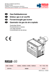
2.
DESCRIZIONE DEL BRUCIATORE
Bruciatore di gas con funzionamento bistadio progressivo o modulante.
³
Marcatura CE secondo direttiva gas 90/396/CEE; PIN 0085BN0609.
Conforme alle direttive: CEM 89/336/CEE - 2004/108/CE, Bassa Tensione 73/23/CEE - 2006/95/CE,
Macchine 98/37/CEE e Rendimenti 92/42/CEE.
Il bruciatore è omologato per funzionamento intermittente secondo la Normativa EN 676.
Il bruciatore risponde al grado di protezione IP X0D (IP 40) secondo EN 60529.
Rampa gas conforme a EN 676.
³
³
³
1
Fig. 1
2
4
8
5
3
6
13
11
10
12
7
9
D4428
1
2
3
4
5
6
7
8
2.1
–
–
–
–
–
–
–
–
9 – Presa 4 poli per collegamento
2° stadio / modulante
10 – Presa 7 poli per alimentazione bruciatore
11 – Presa 6 poli per collegamento rampa
12 – Presa di pressione aria (da collegare al gruppo
valvola gas)
13 – Interruttori per funzionamento:
automatico / manuale (AUT / MAN)
aumento / diminuzione potenza (+/-)
Flangia con schermo isolante
Tubo fiamma
Apparecchiatura di comando e controllo
Pulsante di sblocco con segnalazione di blocco
Gruppo regolazione aria
Vite di regolazione testa di combustione
Pressostato aria
Presa di pressione aria in camera di combustione
(da collegare al gruppo valvola gas)
MATERIALE A CORREDO
Flangia con schermo isolante . . . . . . . . . . . .
Viti e dadi per flangia di fissaggio alla caldaia
Vite e dado per flangia. . . . . . . . . . . . . . . . . .
Tubo in plastica blu . . . . . . . . . . . . . . . . . . . .
.
.
.
.
.
.
.
.
.
.
.
.
.
.
.
.
N° 1
N° 4
N° 1
N° 1
Raccordo a gomito G 1/8 . . . . . . . . . . N° 1
Spina 4 poli . . . . . . . . . . . . . . . . . . . . N° 1
Spina 7 poli . . . . . . . . . . . . . . . . . . . . N° 1
2.2 ACCESSORI (optional):
• KIT (KIT INTERFACCIA PC): cod. 3002719
• KIT REGOLATORE DI POTENZA
Con il funzionamento modulante, il bruciatore adatta automaticamente la potenza erogata tra il suo valore
massimo e minimo, mantenendo costante il parametro, temperatura o pressione, da controllare.
Due componenti devono essere ordinati:
– Regolatore di potenza da installare sul bruciatore;
– Sonda da installare sulla caldaia.
PARAMETRI DA
REGOLARE
Temperatura
Pressione
SONDA
Campo di
regolazione
– 100...+ 500 °C
0...2,5 bar
0...16 bar
REGOLATORE
Tipo
Codice
Tipo
Codice
PT 100
Potenza sonda 4...20 mA
Potenza sonda 4...20 mA
3010110
3010213
3010214
RWF40
3001078
2861
2
I
3.
DATI TECNICI
3.1
DATI TECNICI
TIPO
916M
917M
918M
26/49 ÷ 91
48/79 ÷ 195
68/140 ÷ 250
22,4/42,1 ÷ 78,2
41,3/67,9 ÷ 167,7
58,5/120,4 ÷ 215
kW
Potenza termica (1)
Mcal/h
Pci: 8 ÷ 12 kWh/Nm3
Gas naturale (Famiglia 2)
=
7000 ÷ 10.340 kcal/Nm3
Pressione: min. 20 mbar
–
max. 36 mbar
Monofase, 230V ± 10% ~ 50Hz
Alimentazione elettrica
Motore
0,8 A assorbiti
2800 g/min.
293 rad/s
1,8 A assorbiti
2800 g/min.
293 rad/s
1,9 A assorbiti
2800 g/min.
293 rad/s
4 µF
6,3 µF
8 µF
Condensatore
Primario 230V – 45 VA
Secondario 1 x 15 kV – 25 mA
Trasformatore d’accensione
Potenza elettrica assorbita
0,18 kW
0,35 kW
0,53 kW
(1) Condizioni di riferimento: Temperatura 15°C – Pressione barometrica 1013 mbar – Altitudine 0 m s.l.m.
Per gas della famiglia 3 (GPL) richiedere kit a parte.
PAESE
AT - CH - IS
GB - IE - IT
DE
FR
NL
BE
LU
II2H3B/P
II2H3
II2ELL3B/P
II2Er3P
II2L3B/P
I2E(R)B/I3
II2E3B/P
CATEGORIA GAS
PRESSIONE
GAS
3.2
G20
H
20
20
–
–
–
–
20
G25
L
–
–
20
–
25
–
–
G20
E
–
–
20
20/25
–
20/25
–
DIMENSIONI
F
N
A
D
U
E
45°
H
11
°
45
M
B
C
P
O
øL
G
D4429
R
S
I
T
TIPO
A
B
C
D
E
F
916M
285
280
325 125,5 125,5 352
917M
330
345
391
150
150
918M
330
345
392
150
150
G
H
I
L-U
M
N
O
P
R
S
T
238 ÷ 252 114 ÷ 100
174
106
230
192
66
167
140
170
18
390
262 ÷ 280 128 ÷ 110
196
129
285
216
76,5
201
160
190
21
446
278 ÷ 301 168 ÷ 145
212
137
286
218
80,5
203
170
200
21
2861
3
I
3.3
CAMPI DI LAVORO
CAMPO DI ACCENSIONE 916M
CAMPO DI ACCENSIONE 917M
916M
917M
5,6
combustione – mbar
Pressione in camera di
4,8
4,0
3,2
2,4
1,6
A
0,8
0
-0,5
0
50
100
150
200
kW
D4451
0
50.000
100.000
CAMPO DI ACCENSIONE 918M
150.000
kcal/h
Potenza termica
A
918M
VEDI NOTA A PAG. 11
combustione – mbar
Pressione in camera di
4,8
4,0
3,2
2,4
1,6
0,8
A
0
-0,5
50
100
150
200
250
kW
D4455
50.000
100.000
150.000
200.000
kcal/h
Potenza termica
ATTENZIONE
Per garantire il corretto funzionamento del bruciatore, le partenze devono avvenire sempre entro il relativo campo di accensione (vedi tabella pagina 12).
CALDAIE DI PROVA
Il campo di lavoro è stato ottenuto su caldaie di prova secondo norma EN 676.
CALDAIE COMMERCIALI
L’abbinamento bruciatore-caldaia non pone problemi se la caldaia è conforme alla norma EN 303 e le
dimensioni della sua camera di combustione sono prossime a quelle previste nella norma EN 676.
Se invece il bruciatore viene abbinato ad una caldaia commerciale non conforme alla norma EN 303 o con
dimensioni della camera di combustione nettamente più piccole di quelle indicate nella norma EN 676, consultare i costruttori.
2861
4
I
Pressione gas alla testa
di combustione in mbar
CORRELAZIONE TRA PRESSIONE DEL GAS E POTENZIALITÀ
Per avere la massima potenzialità occorrono 9,3 mbar, relativamente al modello 916M, misurati alla testa
(M2, vedi cap. 4.3, pag. 7) con camera di combustione a 0 mbar e gas G20 – Pci = 9,45 kWh/m3 (8.127 kcal/m3).
10
8
7M
91
6M
91
M
918
6
4
2
0
0
50
0
50.000
100
150
200
250 kW
D4452
4.
100.000
150.000
200.000
kcal/h
Potenza termica
INSTALLAZIONE
L’INSTALLAZIONE DEL BRUCIATORE DEVE ESSERE EFFETTUATA IN CONFORMITÀ ALLE LEGGI E
NORMATIVE LOCALI.
4.1
³
³
³
³
³
FISSAGGIO ALLA CALDAIA
Allargare, se necessario, i fori dello schermo isolante (3, fig. 3), avendo cura di non danneggiarlo.
Montare sulla flangia (5) la presa di pressione (7) fornita a corredo del bruciatore.
Fissare alla portina della caldaia (1, fig. 2) la flangia (5) interponendo lo schermo isolante (3) mediante
le viti (4) e (se necessario) i dadi (2), ma tenendo allentata una delle due viti superiori (4).
Infilare la testa di combustione del bruciatore nella flangia (5), stringere la flangia con la vite (6), quindi
bloccare la vite (4) rimasta allentata.
Verificare che la presa di pressione (7), attraverso lo schermo isolante (3), possa realmente rilevare la
pressione in camera. Se tale segnale non fosse sicuro, provvedere all’inserimento della presa direttamente
collegata alla camera di combustione (ad esempio, attraverso il condotto del visore, se disponibile).
Il mancato collegamento ad una presa di pressione della camera di combustione efficace può portare ad una
funzionamento non sicuro e a probabili accensioni difficoltose.
ATTENZIONE: Il bruciatore può essere
fissato con la quota (A) variabile,
3
come dimostra la figura 4.
Assicurarsi, comunque,
7
che la testa di combustione
attraversi tutto lo
5
spessore della
portina della
4
caldaia.
2
Fig. 3
D5012
A
Fig. 4
1
6
4
Fig. 2
TIPO
916M
917M
918M
E9251
2861
5
I
A
114 ÷ 100
128 ÷ 110
167,5 ÷ 145
D4453
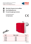
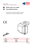
4.2 RAMPA GAS, (secondo EN 676)
La rampa gas viene fornita a parte e per la sua installazione / regolazione vedere le istruzioni che l’accompagnano.
RAMPA GAS
ATTACCHI
Modello
CODICE
BRUCIATORE
ABBINABILE
CG 120
3970587
BS2/M
Rp 3/4”
Flangia 2
Gas naturale e GPL
CG 220
3970588
BS3/M - BS4/M
Rp 3/4”
Flangia 3
Gas naturale e GPL
INGRESSO
USCITA
IMPIEGO
Fig. 5
Legenda
9
1
2
3
4
5
6
Collegamento pressostato gas
Collegamento valvole
Vite per taratura pressostato gas “Pw”
Flangia entrata gas
Vite di regolazione “PUNTO ZERO” (N)
Vite di regolazione “RAPPORTO GAS/
ARIA” (N)
7 - Attacco presa di pressione camera di
combustione “PF”
8 - Attacco pressione aria “PL”
9 - Flangia uscita gas
4
Pw
1
3
N
mbar
5
V
6
8
-
D7035
2
7
Fig. 6
PL
COLLEGAMENTO PRESA DI PRESSIONE
BRUCIATORE ALLA RAMPA GAS
PF
A
Pw
mb a r
N
Per effettuare i suddetti collegamenti procedere
come segue:
V
³
³
³
B
D7034
2861
6
I
Fissare il raccordo da G1/8 (a corredo del
bruciatore) nel punto A (flangia bruciatore).
Tagliare in due parti il tubo in plastica blu
fornito a corredo del bruciatore.
Collegare la presa caldaia A con la presa
d’aria “PF” e la presa manicotto B con la
presa valvola “PL” mediante i tubi precedentemente tagliati.
ATTENZIONE
Il tubo che collega la presa valvola PF con la presa caldaia A deve essere posizionato in modo tale che
l’eventuale condensa venga scaricata in camera di combustione e non all’interno della valvola.
³ E’ necessario mantenere un percorso breve per le linee ad impulsi.
³ E’ opportuno non appoggiare le linee ad impulsi alla caldaia causa danneggiamento dovuto all’alta temperatura.
³ In alcune applicazioni, dove la rilevazione della pressione in camera di combustione risulta imprecisa, è
necessario spostare il raccordo da G1/8 dalla flangia del bruciatore alla portina della caldaia.
In questo caso provvedere a tappare il foro della flangia.
³ La non osservanza di tale avvertenza può causare il mancato funzionamento della valvola, nonché il suo
danneggiamento.
³
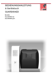
4.3
LINEA DI ALIMENTAZIONE GAS
1
2
3
M1
4
5
6
7
8
M2
Fig. 7
M3
1 – Condotto arrivo gas
2 – Saracinesca manuale
(a carico dell’installatore)
3 – Manometro pressione gas
(a carico dell’installatore)
4 – Filtro
5 – Pressostato gas
6 – Valvola elettromagnetica di
sicurezza
7 – Valvola elettromagnetica di
funzionamento
8 – Regolatore di pressione
4.4
PF
PL
PF – Pressione in camera di combustione
PL – Pressione aria alla testa di combustione
M1 – Presa per la misurazione pressione gas
di alimentazione
M2 – Presa di pressione per la misurazione
del gas all’uscita della rampa
M3 – Presa per la misurazione pressione gas
alla testa di combustione
D4430
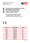
POSIZIONAMENTO SONDA ELETTRODO
Fig. 8
ATTENZIONE
³ Assicurarsi che la piastrina (3, fig. 8) sia sempre
inserita nella spianatura dell’elettrodo (1).
³ Appoggiare l’isolatore della sonda (4) alla tazza (2).
3,5 ± 0,3
TIPO
916M
917M
918M
A ± 0,3
A
30
31
31
1
D6088
2861
7
I
3
4
2
5.
SCHEMI ELETTRICI
5.1
COLLEGAMENTI ELETTRICI STANDARD, (eseguito in fabbrica)
LME 22
D7133
ATTENZIONE:
³ Non scambiare il neutro con la fase, rispettare esattamente lo schema indicato ed eseguire un buon collegamento di terra.
³ La sezione dei conduttori deve essere di min. 1 mm2 . (Salvo
diverse indicazioni di norme e leggi locali).
³ I collegamenti elettrici eseguiti dall’installatore devono rispettare le norme vigenti nel paese.
COLLAUDO
Verificare l’arresto del bruciatore aprendo i termostati ed il
blocco aprendo il connettore (CN3) inserito nel filo rosso della
sonda, posto all’esterno dell’apparecchiatura.
NOTE:
I bruciatori sono stati omologati per funzionamento intermittente.
Ciò significa che devono fermarsi almeno 1 volta ogni 24 ore per
permettere all’apparecchiatura elettrica di effettuare un controllo
della propria efficienza all’avviamento. Normalmente l’arresto
del bruciatore viene assicurato dal termostato limite (TL) della
caldaia. Se così non fosse, è necessario applicare in serie a
(TL) un interruttore orario che provveda all’arresto del bruciatore
almeno una volta ogni 24 ore.
2861
8
I
Legenda
C
– Condensatore motore
CN... – Connettori
F1
– Filtro contro radiodisturbi
MB – Morsettiera ausiliaria
MV – Motore
PA – Pressostato aria di min.
SM – Servomotore
SO – Sonda di ionizzazione
S1 – Interruttore per funzionamento:
MAN = manuale
AUT = automatico
OFF = spento
S2 – Pulsante per:
– = diminuzione potenza
+ = aumento potenza
TA – Trasformatore di accensione
TB – Terra bruciatore
XP4 – Presa 4 poli
XP6 – Presa 6 poli
XP7 – Presa 7 poli
5.2 COLLEGAMENTI ELETTRICI, (a cura dell’installatore)
ATTENZIONE
Se la caldaia è provvista di spina a 7 poli, è indispensabile sostituirla con quella data a corredo
del bruciatore.
SENZA REGOLATORE DI POTENZA (funzionamento bistadio progressivo)
D4548
Legenda:
PS
MB
X7
X4
X6
h2
TR
h1
S
IN
–
–
–
–
–
–
–
–
–
–
Sblocco manuale a distanza
Morsettiera bruciatore
Spina 7 poli
Spina 4 poli
Spina 6 poli
Contaore di 2° stadio
Termostato alta/bassa fiamma
Contaore di 1° stadio
Segnale di blocco remoto
Interruttore manuale
TL
T6A
TS
PG
VR
VS
–
–
–
–
–
–
Termostato di limite
Fusibile
Termostato di sicurezza
Pressostato gas di minima
Elettrovalvola di regolazione
Elettrovalvola di sicurezza
CON REGOLATORE DI POTENZA (funzionamento modulante)
ATTENZIONE
Non collegare nessun contatto tra T6 e T8 della
spina a 4 poli e tra T1 e T2
della spina a 7 poli per evitare interferenze con il
regolatore.
Legenda:
PS
MB
X4
X7
BT
BP
–
–
–
–
–
–
Sblocco manuale a distanza
Morsettiera bruciatore
Spina 4 poli
Spina 7 poli
Sonda di temperatura
Sonda di pressione
D7137
2861
9
I
6.
FUNZIONAMENTO
6.1
REGOLAZIONE DELLA COMBUSTIONE
In conformità con la Direttiva Rendimento 92/42/CEE, l’applicazione del bruciatore alla caldaia, la regolazione e il collaudo, devono essere eseguiti nell’osservanza del manuale d’istruzione della caldaia stessa,
compreso il controllo della concentrazione di CO e CO 2 nei fumi, della loro temperatura e di quella media
dell’acqua della caldaia. A seconda della portata richiesta dalla caldaia va definita la regolazione della testa
di combustione e la regolazione del servomotore serranda aria.
6.2
REGOLAZIONE TESTA DI COMBUSTIONE, (vedi fig. 9)
La regolazione della testa di combustione varia in base alla portata del bruciatore.
Si esegue ruotando in senso orario o antiorario
la vite di regolazione (6) fino a che la tacca incisa sulla staffa di regolazione (2) coincide con il
piano esterno del gruppo testa (1).
Nella figura 9, la staffa di regolazione della testa è tarata alla tacca 3,5.
Esempio per bruciatore tipo 917M:
Il diagramma riportato è orientativo ed indica
la taratura della testa di combustione in funzione alla potenza bruciata. Per garantire le
migliori prestazioni del bruciatore si consiglia
di effettuare tale regolazione in funzione alle
esigenze richieste dal tipo di caldaia.
Il bruciatore è installato in una caldaia da 100 kW.
Considerando un rendimento del 90% il bruciatore dovrà erogare circa 110 kW; per questa
potenzialità la regolazione deve essere effettuata a tacca 3,5.
Fig. 9
6
5
1
3
8
7
11
ESTRAZIONE DEL GRUPPO TESTA
Per l’estrazione del gruppo testa eseguire le
seguenti operazioni:
³ Assicurarsi che il servomotore (7) si trovi in
posizione di chiusura (CAMMA II = 0).
³ Sconnettere i collegamenti (3 e 5).
³ Svitare le viti (4) e togliere il servomotore (7).
4
E9223
kcal/h
ATTENZIONE
L’albero di rotazione (10) gestito dal servo- 210.000
motore (7) è dotato di un meccanismo di sicurezza (11) che ne impedisce la rotazione
accidentale durante le operazioni di ma- 170.000
nutenzione.
³ Svitare la vite (9), allentare le viti (8) ed es130.000
trarre il gruppo porta testa (1) apportando
una lieve rotazione verso destra.
Si raccomanda di non alterare la posizione
di regolazione staffa-gomito (2) nella fase 90.000
di smontaggio.
RIMONTAGGIO DEL GRUPPO TESTA
Rimontare con procedura inversa a quanto
sopra descritto, riposizionando il gruppo testa (1)
come in origine.
9
1
2
10
kW
D4456
250
8M
91
230
210
917M
190
170
150
130
110
90
916M
70
50.000
50
30
10.000
10
0
2
4
6
8
ATTENZIONE
³ Avvitare le viti (9) (senza bloccarle) fino a
battuta; quindi bloccarle con una coppia di serraggio di 3 - 4 Nm.
³ Controllare che, durante il funzionamento, non si verifichino perdite di gas dalle sedi delle viti.
2861
10
I
10
Tacca
A
Per garantire il funzionamento del bruciatore oltre una certa
potenzialità, nei modelli tipo 917M e 918M, è necessario
togliere il fonoassorbente pretranciato per liberare le feritoie
addizionali di ingresso d’aria sul cofano, come illustrato in
figura 10.
TIPO
Potenzialità - kW
917M
> 140
918M
> 200
Fig. 10
S7025
6.3 REGOLAZIONE SERVOMOTORE SERRANDA ARIA, (vedi fig. 11)
Fig. 11
SOSTA
CAMMA II
La CAMMA II assicura la chiusura della serranda
dell’aria, quando il bruciatore è in sosta. E’ regolata in fabbrica a 0°. NON MODIFICARE.
PRIMO STADIO
CAMMA III
La CAMMA III regola la posizione della serranda
dell’aria quando il bruciatore è alla potenza minima. Può essere regolata durante la messa in funzione. La CAMMA IV è solidale alla CAMMA III.
SECONDO STADIO
CAMMA I
La CAMMA I regola la posizione della serranda
dell’aria quando il bruciatore lavora alla potenza
massima. E’ regolata in fabbrica a 90°.
D4438
Il servomotore segue la regolazione della CAMMA III solo quando si riduce l'angolo della camma.
Se bisogna aumentare l'angolo della camma, è necessario prima aumentare l’angolo del servomotore con il tasto “aumento potenza (+)”, poi aumentare l'angolo della CAMMA III ed infine riportare il servomotore nella posizione di potenza MIN con il tasto “diminuzione potenza (-)”.
Per l’eventuale regolazione della CAMMA III, togliere il coperchio (1), inserito a scatto, come indicato nella
fig. 12, estrarre l’apposita chiavetta (2) dal suo interno ed inserirla nell’intaglio della CAMMA III.
Fig. 12
D4439
2861
11
I
6.4
PRIMA ACCENSIONE, (vedi fig. 13 e fig. 5 pag. 6)
Fig. 13
AUT
+
MAN
-
OFF
Dopo aver verificato i collegamenti elettrici e la tenuta delle connessioni idrauliche, posizionare il pressostato dell’aria al valore minimo.
Collegare il manometro alla presa di pressione gas alla testa del bruciatore
(M3, fig. 7 pag. 7).
La tabella seguente indica le impostazioni di accensione riferite ad un bruciatore funzionante con gas metano.
I valori di riferimento sono:
– la potenza di accensione;
– la posizione di pretaratura della serranda aria (CAMMA III);
– la posizione di pretaratura della vite di taratura del PUNTO 0 della rampa gas;
– il modello di rampa gas da utilizzare.
D4468
Potenza di
accensione
Regolazione
CAMMA III
Regolazione
PUNTO 0
Regolaz. RAPPORTO
GAS/ARIA
RAMPA GAS
kW
Tacca N°
Tacca N°
Tacca N°
Modello
26 ÷ 33
20° ÷ 30°
X
917M
48 ÷ 83
30° ÷ 40°
X
918M
68 ÷ 110
30° ÷ 35°
X
917M
48 ÷ 83
30° ÷ 40°
0,1 ÷ 0,25
918M
68 ÷ 110
30° ÷ 35°
-0,7 ÷ -0,5
TIPO
916M
X
CG 120
In funzione della
potenza massima
CG 220
CG 220
In funzione della
potenza massima
MBC - 300 - VEF
MBC - 700 - VEF
Tarare su valori prossimi ad inizio scala (-1,5).
1 - In funzione della potenza massima richiesta regolare la testa di combustione come indicato a pag.10.
2 - Selezionare il modo manuale “MAN” di funzionamento ed effettuare le pretaratura della CAMMA III del
servomotore e della vite di taratura del PUNTO 0 come indicato in tabella, quindi avviare il bruciatore.
3 - Ad accensione avvenuta portare manualmente il servomotore verso la posizione di seconda fiamma
premendo l’interruttore (+). Durante tale operazione controllare la stabilità di fiamma: se risulta instabile aumentare o diminuire la taratura della vite di taratura del RAPPORTO GAS/ARIA leggermente fino
al raggiungimento della massima potenza desiderata e di corretti valori di CO2 nei fumi, quindi
tarare la camma I sul valore raggiunto dal servomotore.
4 - Portare manualmente il servomotore verso la posizione di prima fiamma premendo l’interruttore (-).
Verificare la combustione ed utilizzare, se necessario, la sola vite di taratura del PUNTO 0 per ottenere
corretti valori di CO2 nei fumi.
5 - Se la potenza di prima fiamma deve essere modificata, agire sulla CAMMA III.
Tutte le modifiche della vite di taratura del PUNTO 0 faranno variare anche la portata massima di gas.
6 - Portare nuovamente il servomotore alla massima apertura e verificare nuovamente la potenza massima, agendo sulla vite di taratura del RAPPORTO GAS/ARIA.
7 - Ruotare ancora il servomotore nella posizione di prima fiamma e regolare nuovamente la potenza,
agendo solamente sulla vite di taratura del PUNTO 0.
8 - Ripetere le operazioni (6) e (7), fino a che non sono più richiesti aggiustamenti delle viti di taratura del
RAPPORTO GAS/ARIA e del PUNTO 0.
9 - Controllare i valori della combustione a potenza intermedia e se necessario procedere con ulteriori aggiustamenti delle viti di taratura del RAPPORTO GAS/ARIA e del PUNTO 0.
Al termine, dopo avere verificato che il bruciatore abbia una buona accensione e una buona stabilità di
fiamma, selezionare il funzionamento automatico impostando il selettore sulla posizione “AUT”: la
modulazione avverrà tra la posizione di taratura della CAMMA III e quella della CAMMA I.
2861
12
I
6.5 CONTROLLO DELLA COMBUSTIONE
In conformità con la Direttiva Rendimento 92/42/CEE, l’applicazione del bruciatore alla caldaia, la
regolazione e il collaudo, devono essere eseguiti nell’osservanza del manuale d’istruzione della caldaia
stessa, compreso il controllo della concentrazione di CO e CO2 nei fumi, della loro temperatura e di quella
media dell’acqua della caldaia.
È consigliabile regolare il bruciatore, a seconda del tipo di gas utilizzato, secondo le indicazioni fornite nella
tabella seguente:
ECCESSO D’ARIA:
potenza max. λ ≤ 1,2 – potenza min. λ ≤ 1,3
EN 676
GAS
CO2 max. teorico
0 % O2
G 20
G 30
G 31
11,7
14,0
13,7
Taratura
CO2 %
λ = 1,2
9,7
11,6
11,4
λ = 1,3
9,0
10,7
10,5
CO
mg/kWh
≤ 100
≤ 100
≤ 100
NOx
mg/kWh
≤ 170
≤ 230
≤ 230
CORRENTE DI IONIZZAZIONE
La corrente minima per far funzionare l’apparecchiatura è 2 µA. Il bruciatore dà una corrente nettamente
superiore, tale da non richiedere normalmente alcun controllo. Qualora, comunque, si voglia misurare la corrente di ionizzazione bisogna aprire il connettore (CN3) (vedi schema elettrico pag. 8) inserito nel filo rosso
ed inserire un microamperometro.
Connettore
Morsettiera
apparecchiatura
1
D5006
6.6
Sonda
PRESSOSTATO ARIA
Eseguire la regolazione del pressostato aria dopo aver effettuato tutte le altre regolazioni del bruciatore con il
pressostato aria regolato a inizio scala. Con il bruciatore funzionante alla potenza minima, ruotare la manopola lentamente in senso orario fino al blocco del bruciatore. Ruotare quindi la manopola in senso antiorario di
un valore pari a circa il 20% del valore regolato e verificare successivamente il corretto avviamento del bruciatore. Se il bruciatore si blocca nuovamente, ruotare ancora un poco la manopola in senso antiorario.
Attenzione:
Per norma il pressostato aria deve impedire che la pressione dell’aria scenda al di sotto dell’ 80% del valore di regolazione e che il CO nei fumi superi l’ 1% (10.000 ppm).
Per accertarsi di ciò, inserire un analizzatore della combustione nel camino, chiudere lentamente la bocca di
aspirazione del ventilatore (per esempio con un cartone) e verificare che avvenga il blocco del bruciatore,
prima che il CO nei fumi superi l’ 1%.
6.7
PRESSOSTATO GAS
Per la taratura del pressostaro gas è necessario fare riferimento al manuale d’istruzione della rampa gas.
2861
13
I
6.8
PROGRAMMA DI AVVIAMENTO
Termostato limite
Termostato di sicurezza
Motore
{
2
Motore apriserranda 1
0
Trasformatore
Valvola gas
2a fiamma
1a fiamma
24s
Min. 30s
D4435
15 ÷ 25s
2,5s
11s
3s
3s max.
11s
7.
MANUTENZIONE
Il bruciatore richiede una manutenzione periodica, che deve essere eseguita da personale abilitato e in
conformità alle leggi e normative locali.
La manutenzione diventa essenziale per un buon funzionamento del bruciatore, evitando in questo modo
consumi eccessivi di combustibile e riducendo pertanto le emissioni inquinanti nell’ambiente.
Prima di effettuare qualsiasi operazione di pulizia o controllo, togliere l’alimentazione elettrica al
bruciatore agendo sull’interruttore generale dell’impianto.
LE OPERAZIONI BASILARI DA EFFETTUARE SONO LE SEGFig. 14
UENTI:
³ Verificare periodicamente la possibile ostruzione dei fori del
distributore gas e, se necessario, pulire con un utensile appuntito come illustrato nella figura 14.
³ Verificare che non ci siano occlusioni o strozzature nei tubi di
alimentazione e ritorno del combustibile, nelle zone di aspirazione aria e nei condotti di evacuazione dei prodotti della
combustione.
³ Verificare la corretta esecuzione dei collegamenti elettrici del
bruciatore e della rampa gas.
³ Verificare che la rampa gas sia idonea alla potenzialità del bruciatore, al tipo di gas utilizzato ed alla pressione gas della rete.
³ Verificare il corretto posizionamento della testa di combusE9252
tione e del suo fissaggio alla caldaia.
³ Verificare il corretto posizionamento della serranda aria.
³ Verificare il corretto posizionamento della sonda di ionizzazione e dell'elettrodo (vedi fig. 8, pag. 7).
³ Verificare la regolazione del pressostato aria e del pressostato gas.
Lasciare funzionare il bruciatore a pieno regime per circa dieci minuti, controllando le corrette tarature
in 1° e 2° stadio di tutti gli elementi indicati nel presente manuale.
Quindi effettuare un’analisi della combustione verificando:
●
●
Percentuale di CO2 (%);
Corrente di ionizzazione (µA);
●
●
Contenuto di CO (ppm);
Temperatura dei fumi al camino.
2861
14
I
●
Contenuto NOx (ppm);
8.
ANOMALIE / RIMEDI
L’apparecchiatura in dotazione ha una sua funzione diagnostica attraverso la quale è possibile facilmente
individuare le possibili cause di mal funzionamento.
Per utilizzare tale funzione, bisogna aspettare almeno dieci secondi dall’istante di messa in sicurezza
dell’apparecchiatura e premere il pulsante di sblocco per un tempo minimo di tre secondi.
Dopo aver rilasciato il pulsante, il LED ROSSO comincerà a lampeggiare, come illustrato nella seguente
tabella.
LED ROSSO acceso
Premere sblocco
per > 3s
aspettare per almeno 10s
Segnale
3s
Segnale
Gli impulsi del LED costituiscono un segnale intervallato da 3 secondi circa.
Il numero degli impulsi darà le informazioni sui possibili guasti, secondo la seguente legenda:
SEGNALE
2
3
4
5
7
10
POSSIBILE CAUSA
Non viene rilevato un segnale stabile di fiamma nel tempo di sicurezza:
– guasto alla sonda di ionizzazione;
– guasto alla valvola del gas;
– inversione fase/neutro;
– bruciatore non regolato.
Il pressostato aria di minima non chiude:
– verificare intervento di blocco VPS;
– guasto al pressostato aria;
– pressostato aria non regolato;
– il motore della girante non funziona;
– intervento del pressostato aria di massima.
Luce presente in camera durante la preventilazione, oppure guasto
all’apparecchiatura.
Il pressostato aria di minima non commuta:
– guasto al pressostato aria;
– pressostato aria non regolato.
Sparizione della fiamma durante il funzionamento:
– bruciatore non regolato;
– guasto alla valvola del gas;
– cortocircuito tra la sonda di ionizzazione e la terra.
Apparecchiatura guasta.
2861
15
I
INHALT
1.
ALLGEMEINE INFORMATIONEN. . . . . . . . . . . . . . . . . . . . . . . . . . . . . . . . . . . . . . . . . . . . . . . . . . . 1
2.
BESCHREIBUNG DES BRENNERS . . . . . . . . . . . . . . . . . . . . . . . . . . . . . . . . . . . . . . . . . . . . . . . . . 2
2.1
Mitgeliefertes Zubehör . . . . . . . . . . . . . . . . . . . . . . . . . . . . . . . . . . . . . . . . . . . . . . . . . . . . . . . . . . . . 2
2.2
Zubehör. . . . . . . . . . . . . . . . . . . . . . . . . . . . . . . . . . . . . . . . . . . . . . . . . . . . . . . . . . . . . . . . . . . . . . . 3
3.
TECHNISCHE MERKMALE . . . . . . . . . . . . . . . . . . . . . . . . . . . . . . . . . . . . . . . . . . . . . . . . . . . . . . . 3
3.1
Technische Daten . . . . . . . . . . . . . . . . . . . . . . . . . . . . . . . . . . . . . . . . . . . . . . . . . . . . . . . . . . . . . . . 3
3.2
Abmessungen . . . . . . . . . . . . . . . . . . . . . . . . . . . . . . . . . . . . . . . . . . . . . . . . . . . . . . . . . . . . . . . . . . 3
3.3
Arbeitsfelder . . . . . . . . . . . . . . . . . . . . . . . . . . . . . . . . . . . . . . . . . . . . . . . . . . . . . . . . . . . . . . . . . . . 4
4.
INSTALLATION . . . . . . . . . . . . . . . . . . . . . . . . . . . . . . . . . . . . . . . . . . . . . . . . . . . . . . . . . . . . . . . . 5
4.1
Brennermontage . . . . . . . . . . . . . . . . . . . . . . . . . . . . . . . . . . . . . . . . . . . . . . . . . . . . . . . . . . . . . . . . 5
4.2
Gasstrecke . . . . . . . . . . . . . . . . . . . . . . . . . . . . . . . . . . . . . . . . . . . . . . . . . . . . . . . . . . . . . . . . . . . . 6
4.3
Gasanschluss-Schema . . . . . . . . . . . . . . . . . . . . . . . . . . . . . . . . . . . . . . . . . . . . . . . . . . . . . . . . . . . 7
4.4
Fühler - und Elektrodenstellung . . . . . . . . . . . . . . . . . . . . . . . . . . . . . . . . . . . . . . . . . . . . . . . . . . . . . 7
5.
SCHALTPLÄNE . . . . . . . . . . . . . . . . . . . . . . . . . . . . . . . . . . . . . . . . . . . . . . . . . . . . . . . . . . . . . . . . 8
5.1
Elektrische Anlage (Werkseitig ausgeführt) . . . . . . . . . . . . . . . . . . . . . . . . . . . . . . . . . . . . . . . . . . . 8
5.2
Elektrische Anschlüsse (Vom Installateur auszuführen). . . . . . . . . . . . . . . . . . . . . . . . . . . . . . . . . . . 9
6.
BETRIEB . . . . . . . . . . . . . . . . . . . . . . . . . . . . . . . . . . . . . . . . . . . . . . . . . . . . . . . . . . . . . . . . . . . . 10
6.1
Einstellung der Brennerleistung . . . . . . . . . . . . . . . . . . . . . . . . . . . . . . . . . . . . . . . . . . . . . . . . . . . . 10
6.2
Einstellung des Brennerkopfes . . . . . . . . . . . . . . . . . . . . . . . . . . . . . . . . . . . . . . . . . . . . . . . . . . . . 10
6.3
Einstellung des Luftklappenstellantriebs . . . . . . . . . . . . . . . . . . . . . . . . . . . . . . . . . . . . . . . . . . . . . 11
6.4
Erste Zündung. . . . . . . . . . . . . . . . . . . . . . . . . . . . . . . . . . . . . . . . . . . . . . . . . . . . . . . . . . . . . . . . . 12
6.5
Verbrennungskontrolle . . . . . . . . . . . . . . . . . . . . . . . . . . . . . . . . . . . . . . . . . . . . . . . . . . . . . . . . . . 13
6.6
Minimalluftdruckwächter . . . . . . . . . . . . . . . . . . . . . . . . . . . . . . . . . . . . . . . . . . . . . . . . . . . . . . . . . 13
6.7
Gasdruckwächter . . . . . . . . . . . . . . . . . . . . . . . . . . . . . . . . . . . . . . . . . . . . . . . . . . . . . . . . . . . . . . 13
6.8
Betriebsablauf . . . . . . . . . . . . . . . . . . . . . . . . . . . . . . . . . . . . . . . . . . . . . . . . . . . . . . . . . . . . . . . . . 14
7.
WARTUNG . . . . . . . . . . . . . . . . . . . . . . . . . . . . . . . . . . . . . . . . . . . . . . . . . . . . . . . . . . . . . . . . . . . 14
8.
STÖRUNGEN / ABHILFE . . . . . . . . . . . . . . . . . . . . . . . . . . . . . . . . . . . . . . . . . . . . . . . . . . . . . . . . 15
2861
D
1.
ALLGEMEINE INFORMATIONEN
IDENTIFIZIERUNG
Auf dem Typenschild sind die Seriennummer, das Modell und die wichtigsten technischen Angaben und
Leistungsdaten angegeben. Durch eine Beschädigung und/oder Entfernung und/oder das Fehlen des
Typenschildes kann das Produkt nicht genau identifiziert werden, wodurch Installations- und Wartungsarbeiten schwierig und/oder gefährlich werden.
ALLGEMEINE HINWEISE
Um bestmögliche Verbrennungs-Ergebnisse sowie niedrige Emissionswerte zu erzielen, muß die Brennkammer-Geometrie des Heizkessels für den Brenner geeignet sein.
Deshalb ist es notwendig, vor Einsatz des Brenners Informationen bei einzuholen, um ein einwandfreies Funktionieren des Brenners zu gewährleisten.
Dieser Brenner darf nur für den Einsatzzweck verwendet werden, für den er hergestellt wurde.
Eine vertragliche und außervertragliche Haftung des Herstellers für Personen-, Tier- und Sachschäden aufgrund von Fehlern bei der Installation, der Einstellung, der Wartung und aufgrund von unsachgemäßem Gebrauch ist ausgeschlossen.
INFORMATIONEN FÜR DEN BENUTZER
Im Falle von Störungen bei Zündung oder Betrieb wird der Brenner ein „Sicherheitsabschalten“ ausführen,
erkennbar an der roten Störabschaltungsmeldung des Brenners. Um die Bedingungen für das Einschalten
wieder herzustellen, muss auf die Entriegelungstaste gedrückt werden.
Das rote Licht wird bei erneutem Anfahren des Brenners erlöschen. Dieser Vorgang kann höchstens 3 Mal
wiederholt werden. Wenn sich die “Sicherheitsabschaltungen” wiederholen, muss der Kundendienst zu
Rate gezogen werden.
GRUNDLEGENDE SICHERHEITSVORSCHRIFTEN
³
Der Gebrauch des Geräts durch Kinder oder Unerfahrene ist verboten.
³
Es ist absolut verboten, die Ansaug- oder Dissipationsgitter und die Belüftungsöffnung des Installationsraumes des Geräts mit Lumpen, Papier oder sonstigem zu verstopfen.
³
Reparaturversuche am Gerät durch nicht autorisiertes Personal sind verboten.
³
Es ist gefährlich, an elektrischen Kabeln zu ziehen oder diese zu biegen.
³
Reinigungsarbeiten vor der Abschaltung des Geräts vom elektrischen Versorgungsnetz sind verboten.
³
Den Brenner und seine Teile nicht mit leicht entzündbaren Substanzen (wie Benzin, Spiritus, usw.) reinigen. Die Brennerhaube darf nur mit Seifenwasser gereinigt werden.
³
Keine Gegenstände auf den Brenner legen.
³
Die Belüftungsöffnungen des Installationsraums des Erzeugers nicht verstopfen bzw. verkleinern.
³
Keine Behälter und entzündbare Stoffe im Installationsraum des Geräts lassen.
2861
1
D
2.
BESCHREIBUNG DES BRENNERS
Gasbrenner mit zweistufig-gleitendem oder modulierendem Betrieb mit Anbringung eines Leistungsreglersatzes.
³
³
³
³
CE Kennzeichnung gemäß der Gasgeräterichtlinie 90/396/EWG; PIN 0085BN0609.
Gemäß Richtlinien: EMV 89/336/EWG - 2004/108/EG, Niederspannungsrichtlinie 73/23/EWG - 2006/
95/EG, Maschinenrichtlinie 98/37/EWG und Wirkungsgradrichtlinie 92/42/EWG.
Der Brenner ist gemäß der Norm EN 676 für intermittierenden Betrieb typgenehmigt.
Der Brenner entspricht der Schutzart IP X0D (IP 40) gemäß EN 60529.
Gasstrecke gemäß der Euronorm EN 676.
1
2
4
8
5
Abb. 1
3
6
13
11
10
12
7
9
D4428
1
2
3
4
5
6
7
8
2.1
–
–
–
–
–
–
–
–
Kesselflansch mit Isolierdichtung
Flammrohr
Steuergerät
Entstörtaste mit Störanzeige
Luft-Einstellgruppe
Kopf-Stellschraube
Minimaldruckwächter
Luftdruckentnahmestelle in der Brennkammer (an der Gasventilgruppe anzuschließen)
9 – 4-polige Steckdose für den Anschluss
der 2. Stufe / modulierend
10 – 7 - polige Steckdose für die Brennerversorgung
11 – 6 - polige Steckdose für Gasstrecke
12 – Luftdruckentnahmestelle (an der Gasventilgruppe
anzuschließen)
13 – Betriebsschalter für:
automatischen / manuellen Betrieb (AUT / MAN)
steigerung / reduzierung der Leistung (+/-)
MITGELIEFERTES ZUBEHÖR
Kesselflansch mit Isolierdichtung . . . . . . . . . . . . . . 1 St.
Kniegelenk G 1/8
Blaues Plastikrohr. . . . . . . . . . . . . . . . . . . . . . . . . . 1 St.
4 poliger Stecker
Schraube und Muttern für Brennerflansch . . . . . . . 1 St.
7 poliger Stecker .
Schrauben und Muttern für Befestigungsflansch am Heizkessel . . . . . . . . . . . . .
.
.
.
.
.
.
.
.
.
.
.
.
.
.
.
.
.
.
.
.
.
.
.
.
.
.
.
.
.
.
.
.
.
.
.
.
.
.
.
.
.
.
.
.
.
.
.
.
.
.
.
.
.
.
.
.
.
.
.
.
.
.
.
.
1
1
1
4
St.
St.
St.
St.
2.2 ZUBEHÖR (Optionals):
• SATZ (SATZ PC SCHNITTSTELLE): cod. 3002719
• SATZ LEISTUNGSREGLER
Bei modulierendem Betrieb passt der Brenner die abgegebene Leistung automatisch zwischen Höchstund Mindestwert an, wobei der zu regelnde Temperatur- oder Druckwert konstant bleibt.
Es müssen zwei Komponenten bestellt werden:
– Leistungsregler, am Brenner zu installieren;
– Fühler, am Heizkessel zu installieren.
REGELPARAMETER
Temperatur
Gasdruck
Regelbereich
– 100...+ 500 °C
0...2,5 bar
0...16 bar
FÜHLER
Typ
PT 100
Leistung des 4...20 mA Fühlers
Leistung des 4...20 mA Fühlers
2861
2
D
Code
3010110
3010213
3010214
REGLER
Typ
Code
RWF40
3001078
3.
TECHNISCHE MERKMALE
3.1
TECHNISCHE DATEN
TYP
916M
917M
918M
26/49 ÷ 91
48/79 ÷ 195
68/140 ÷ 250
22,4/42,1 ÷ 78,2
41,3/67,9 ÷ 167,7
58,5/120,4 ÷ 215
kW
Brennerleistung (1)
Mcal/h
Unterer Heizwert: 8 ÷ 12 kWh/Nm3
Erdgas (Familie 2)
Anschlussdruck:
7000 ÷ 10.340 kcal/Nm3
=
Min. 20 mbar
–
Max. 36 mbar
Einphasig, 230V ± 10% ~ 50Hz
Stromversorgung
Motor
0,8 A Stromaufn.
2800 U/min.
293 rad/s
1,8 A Stromaufn.
2800 U/min.
293 rad/s
1,9 A Stromaufn.
2800 U/min.
293 rad/s
4 µF
6,3 µF
8 µF
Kondensator
Primär 230V – 45 VA
Sekundär 1 x 15 kV – 25 mA
Zündtransformator
Leistungsaufnahme
0,18 kW
(1) Bedingungen: Temperatur 15°C
–
0,35 kW
Luftdruck 1013 mbar
–
0,53 kW
Höhe 0 m auf Meereshöhe.
Für Gas der 3. Gasfamilie (Flüssiggas) Umstellsatz anfordern.
LAND
AT - CH - IS
GB - IE - IT
DE
FR
NL
BE
LU
II2H3B/P
II2H3
II2ELL3B/P
II2Er3P
II2L3B/P
I2E(R)B/I3
II2E3B/P
GASKATEGORIE
GASANSCHLUSSDRUCK
3.2
G20
H
20
20
–
–
–
–
20
G25
L
–
–
20
–
25
–
–
G20
E
–
–
20
20/25
–
20/25
–
ABMESSUNGEN
F
N
A
D
U
E
45°
H
°
11
M
45
B
C
P
O
øL
G
D4429
R
S
I
T
TYP
A
B
C
D
E
F
916M
285
280
325 125,5 125,5 352
917M
330
345
391
150
150
918M
330
345
392
150
150
G
H
I
L-U
M
N
O
P
R
S
T
238 ÷ 252 114 ÷ 100
174
106
230
192
66
167
140
170
18
390
262 ÷ 280 128 ÷ 110
196
129
285
216
76,5
201
160
190
21
446
278 ÷ 301 168 ÷ 145
212
137
286
218
80,5
203
170
200
21
2861
3
D
3.3
ARBEITSFELDER
ZÜNDUNGSFELD 916M
ZÜNDUNGSFELD 917M
916M
917M
5,6
4,0
mbar
Druck im Feuerraum
4,8
3,2
2,4
1,6
A
0,8
0
-0,5
0
50
100
150
200
kW
D4451
0
50.000
kcal/h
150.000
Brennerleistung
100.000
ZÜNDUNGSFELD 918M
A
918M
SIEHE ANMERKUNG AUF SEITE 11
4,0
3,2
mbar
Druck im Feuerraum
4,8
2,4
1,6
0,8
A
0
-0,5
50
100
150
200
250
kW
D4455
50.000
100.000
150.000
200.000
kcal/h
Brennerleistung
ACHTUNG
Um den korrekten Brennerbetrieb zu gewährleisten, müssen die Starts immer innerhalb des jeweiligen Zündungsfeldes erfolgen (siehe Tabelle auf Seite 12).
PRÜFKESSEL
Das Arbeitsfeld wurde an einem Prüfkessel, gemäß der Norm EN 676, ermittelt.
HANDELSÜBLICHE HEIZKESSEL
Die Abstimmung Brenner-Kessel ist ohne Probleme, wenn der Kessel der Euronorm EN 303 entspricht und
die Abmessungen des Feuerraumes mit Euronorm EN 676 übereinstimmen.
Wenn der Brenner mit einem Heizkessel kombiniert werden soll, der nicht der Euronorm EN 303 und der
EN 676 entspricht, müssen die technischen Daten aufeinander abgestimmt werden. Die Kesseldaten beim
Hersteller abfragen.
2861
4
D
VOM GASDRUCK AM BRENNERKOPF ABHÄNGIGE BRENNERLEISTUNG
Um die maximale Leistung zu erhalten, sind für das Modell 916M 9,3 mbar, am Kopf (M2, siehe Punkt 4.3, S. 7)
gemessen und mit Brennkammer auf 0 mbar und Gas G20 – Pci = 9,45 kWh/m3 (8.127 kcal/m3), erforderlich.
Gasdruck im mbar
am Brennerkopf
10
8
7M
91
6M
91
M
918
6
4
2
0
0
50
100
0
50.000
150
200
250 kW
D4452
4.
100.000
150.000
200.000
kcal/h
Brennerleistung
INSTALLATION
DIE INSTALLATION DES BRENNERS MUSS IN ÜBEREINSTIMMUNG MIT DEN ÖRTLICHEN GESETZEN
UND VORSCHRIFTEN AUSGEFÜHRT WERDEN.
4.1
³
³
³
³
³
BRENNERMONTAGE
Falls nötig, die Bohrungen am Wärmeschild (3, Abb. 3) vergrößern, dieses dabei aber nicht beschädigen.
Die mit dem Brenner gelieferte Druckentnahmestelle (7) an den Flansch (5) montieren.
Mit den Schrauben (4) (falls erforderlich) den Muttern (2) an der Kesseltür (1) den Flansch (5) mit Isolierdichtung (3) montieren, aber eine der zwei höheren Schrauben losschrauben (Siehe Abb. 2).
Den Verbrennungskopf des Brenners an dem Flansch (5) einsetzen, den Flansch mit der Schraube (6)
anziehen und dann die Schraube (4) blockieren, die losschraubt war.
Prüfen, dass die Druckentnahmestelle (7) durch das Wärmeschild (3) effektiv den Druck in der Kammer
messen kann. Sollte dieses Signal nicht sicher sein, die Druckentnahmestelle direkt in der Brennkammer
anschließen (z.B. durch die Leitung des Sichtgeräts, falls vorhanden). Der nicht erfolgte Anschluss der
Brennkammer an einer wirksamen Druckentnahmestelle kann einen nicht sicheren Betrieb und sogar
schwierige Zündungen verursachen.
ACHTUNG: Der Brenner kann mit dem
3
veränderlichen Maß (A) befestigt
werden (Siehe Abb. 4).
7
Der Verbrennungskopf soll
die ganze Stärke der
5
Kesseltür durchgehen.
2
Abb. 3
D5012
4
A
Abb. 4
1
6
4
Abb. 2
TYP
916M
917M
918M
E9251
2861
5
D
A
114 ÷ 100
128 ÷ 110
167,5 ÷ 145
D4453
4.2 GASSTRECKE, (nach EN 676)
Die Gasstrecke wird gesondert geliefert; für ihre Installation / Einstellung wird auf die ihr beiliegenden Anleitungen verwiesen.
GASSTRECKE
ANSCHLÜSSE
Modell
CODE
ABGESTIMMTER
BRENNER
CG 120
3970587
BS2/M
Rp 3/4”
Flansch 2
Erdgas und Flüssiggas
CG 220
3970588
BS3/M - BS4/M
Rp 3/4”
Flansch 3
Erdgas und Flüssiggas
EINGANG
AUSGANG
GEBRAUCH
Abb. 5
Zeichenerklärung
1 - Verbindung Gasdruckwächter
2 - Verbindung Ventil
3 - Schraube zur Eichung des Gasdruckwächters “Pw”
4 - Flansch, Gaseintritt
5 - Stellschraube “NULLPUNKT-STELLSCHRAUBE” (N)
6 - Stellschraube für das GAS-/LUFTVERHÄLTNIS (V)
7 - Brennkammerdruckentnahmestelle “PF”
8 - Luftdruckanschluss “PL”
9 - Flansch, Gasaustritt
9
4
Pw
1
3
N
mbar
5
V
6
8
D7035
2
7
Abb. 6
PL
ANSCHLUSS DER GASDRUCKENTNAHMESTELLEN MIT DEN GASARMATUREN
PF
A
Pw
mb a r
N
Zur Durchführung der oben genannten
Anschlüsse wie folgt vorgehen:
V
³
³
³
B
D7034
2861
6
D
Das Anschlussstück zu G1/8 (mit dem Brenner geliefert) an Punkt A (Brennerflansch)
befestigen.
Das mit dem Brenner gelieferte, blaue Plastikrohr in zwei Teile schneiden.
Die Heizkesselentnahmestelle A mit der
Ventilentnahmestelle “PF” und die Entnahmestelle B an der Muffe mit der Ventilentnahmestelle “P F ” mit Hilfe der vorher
geschnittenen Rohre verbinden.
ACHTUNG
Das Verbindungsrohr zwischen Ventilsteckanschluss P F und Heizkesselsteckanschluss A muss so
angebracht werden, dass Kondensat in die Brennkammer, nicht in das Ventil entladen wird.
³ Die Schlauchleitungen müssen auf einer kurzen Strecke verlegt werden.
³ Die Schlauchleitungen nicht am Heizkessel aufliegen lassen, um Beschädigungen infolge hoher Temperatur
zu vermeiden.
³ Bei einigen Anwendungen, wo die Druckmessung in der Brennkammer ungenau ist, muss das
Anschlussstück zu G1/8 vom Brennerflansch zur Heizkesseltür verschoben werden.
In diesem Fall die Flanschbohrung mit einem Stopfen verschließen.
³ Wenn diese Vorschrift nicht beachtet wird, könnte das Ventil nicht funktionieren oder beschädigt werden.
³
4.3
GASANSCHLUSS–SCHEMA
1
2
3
M1
4
5
6
7
8
M2
Abb. 7
M3
1 – Gaszuleitung
2 – Handabsperrschieber
(Sonderzubehör)
3 – Gasdruckmanometer
(Sonderzubehör)
4 – Filter
5 – Gasdruckwächter
6 – Elektromagnetisches
Sicherheitsventil
7 – Elektromagnetisches
Betriebsventil
8 – Druckregler
4.4
PF
PL
PF
PL
M1
M2
–
–
–
–
Brennkammerdruck
Luftdruck am Brennerkopf
Messung, Anschlußdruck
Druckentnahmestelle zur Messung
des Gases am Ausgang der Gasstrecke
M3 – Druckentnahmestelle zur Messung
des Gasdrucks am Flammkopf
D4430
FÜHLER - UND ELEKTRODENSTELLUNG
Abb. 8
ACHTUNG
³ Das Einfügen der Platte (3, Abb. 8) in der Abflachung der Elektrode (1) nachprüfen.
³ Den Isolator des Fühlers (4) an die Tasse (2) lehnen.
3,5 ± 0,3
TYP
916M
917M
918M
A ± 0,3
A
30
31
31
1
D6088
2861
7
D
3
4
2
5.
SCHALTPLÄNE
5.1
ELEKTRISCHE ANLAGE (Werkseitig ausgeführt)
LME 22
D7133
ACHTUNG:
³ Nullleiter nicht mit Phase austauschen; sich genau an das angegebene Schema halten und eine gute Erdung ausführen.
³ Der Leiterquerschnitt muss mindestens 1 mm2 sein.
(Außer im Falle anderslautender Angaben durch Normen und örtliche Gesetze).
³ Die vom Installateur ausgeführten elektrischen Verbindungen müssen den lokalen Bestimmungen entsprechen.
PRÜFUNG
Bei der Öffnung der Kessel-Thermostaten wird die Brennerabschaltung überprüft, und bei der Öffnung des Verbinders (CN3), der im
roten Kabel des Ionisationsstromkreises außerhalb des Gerätes eingesetzt ist, wird das Störrelais überprüft.
ANMERKUNGEN:
Das bedeutet, dass sie mindestens 1 Mal alle 24 Stunden anhalten
müssen, damit das elektrische Steuergerät eine Kontrolle seiner Effizienz beim Anfahren ausführen kann. Gewöhnlich wird das Anhalten
des Brenners durch den Begrenzungsthermostat (TL) des Heizkessels gewährleistet. Sollte dies nicht der Fall sein, muss ein Zeitschalter mit (TL) seriengeschaltet werden, der für das Anhalten des
Brenners mindestens einmal alle 24 Stunden sorgt.
2861
8
D
Zeichenerklärung
C
– Kondensator
CN... – Verbinder
F1
– Funk-enstörfilter
MB – Hilfsklemmleiste
MV – Motor
PA – Minimalluftdruckwächter
SM – Stellantrieb
SO – Flammenfühler
S1 – Schalter für:
MAN = manuell
AUT = automatisch
OFF = aus
S2 – Druckknopf für:
– = Leistungsreduzierung
+ = Leistungserhöhung
TA – Zündtransformator
TB – Brenner-Erdung
XP4 – 4- polige Steckdose
XP6 – 6- polige Steckdose
XP7 – 7- polige Steckdose
5.2 ELEKTRISCHE ANSCHLÜSSE (Vom Installateur auszuführen)
WICHTIGER HINWEIS
Falls der Heizkessel keinen 7-polligen Stecker hat, muss er durch den mit dem Brenner gelieferten
ersetzt werden.
OHNE LEISTUNGSREGLER (Zweistufig-gleitender Betrieb)
D4548
Zeichenerklärung:
PS
MB
X7
X4
X6
h2
TR
h1
S
IN
–
–
–
–
–
–
–
–
–
–
Manuelle Fernentriegelung
Brennerklemmleiste
7- poliger Stecker
4- poliger Stecker
6- poliger Stecker
2. Stufe Stundenzähler
Thermostat hohe/niedrige Flamme
1. Stufe Stundenzähler
Fernsignal Störabschaltung
Manueller Schalter
TL –
T6A –
TS –
PG –
VR –
VS –
Grenzthermostat
Sicherung
Sicherheitsthermostat
Minimalgasdruckwächter
Regelmagnetventil
Sicherheitsventil
MIT LEISTUNGSREGLER (Modulierender Betrieb)
ACHTUNG
Keinen Kontakt zwischen
T6 und T8 des 4-poligen
Steckers und zwischen T1
und T2 des 7-poligen Stekkers anschließen, um Interferenzen mit dem Regler zu
vermeiden.
Zeichenerklärung:
PS
MB
X4
X7
BT
BP
–
–
–
–
–
–
Manuelle Fernentriegelung
Brennerklemmleiste
4- poliger Stecker
7- poliger Stecker
Temperaturfühler
Druckfühler
D7137
2861
9
D
6.
BETRIEB
6.1
EINSTELLUNG DER BRENNERLEISTUNG
In Konformität mit der Wirkungsgradrichtlinie 92/42/EWG müssen die Anbringung des Brenners am Heizkessel, die Einstellung und die Inbetriebnahme unter Beachtung der Betriebsanleitung des Heizkessels ausgeführt werden, einschließlich Kontrolle der Konzentration von CO und CO 2 in den Abgasen, der
Abgastemperatur und der mittlenen Kesseltemperatur. Entsprechend der gewünschten Kesselleistung werden die Einstellung des Brennkopfes und des Luftklappenstellantriebs bestimmt.
6.2
BRENNERKOPFEINSTELLUNG, (siehe Abb. 9)
Die Brennerkopfeinstellung ist je nach Brennerdurchsatz verschieden.
Sie erfolgt, indem die Stellschraube (6) im oder
gegen den Uhrzeigersinn gedreht wird, bis die
Raste auf der Regulierspindel (2) mit der
Außenfläche des Kopfblocks (1) zusammenfällt.
In Abbildung 9 ist die Kopfregulierspindel auf
Raste 3,5 geeicht.
5
Beispiel für Brenner Typ 917M:
Das angegebene Diagramm dient nur als Hinweis und zeigt die Brennerkopfeichung je nach
gelieferter Leistung. Um die besten Brennerleistungen zu garantieren, wird empfohlen,
den Kopf je nach Bedarf des Heizkesseltyps
einzustellen.
Der Brenner wird in einem 100 kW Heizkessel
installiert. Mit einer Leistung von 90% muss
der Brenner ca. 110 kW liefern, wenn die
Spindel auf Raste 3,5 gestellt ist.
9
6
1
3
8
7
11
ENTNAHME DES KOPFBLOCKS
U m den Kopfblock herauszunehmen, fol4
gende Vorgänge ausführen:
³ Sicher stellen, dass sich der Stellantrieb (7)
in geschlossener Stellung befindet
(NOKKEN II = 0).
³ Die Verbindungen (3 und 5) abtrennen.
³ Die Schrauben (4) losschrauben und den
kcal/h
kW
Stellantrieb (7) entfernen.
210.000
ACHTUNG
Die vom Stellantrieb (7) betriebene Drehwelle
(10) ist mit einem Sicherheitsmechanismus
(11) ausgestattet, der eine zufällige Drehung 170.000
während der Wartungsarbeiten verhindert.
³ Die Schraube (9) losschrauben, die Schrauben
130.000
(8) lockern und den Kopfblockhalter (1) mit
einer leichten Rechtsdrehung herausnehmen.
Es wird empfohlen, die Lage von Einstellspindel und Knie (2) während der Demontage 90.000
nicht zu ändern.
ERNEUTE MONTAGE DES KOPFBLOCKS
Für die erneute Montage das oben Beschriebene auf umgekehrte Art ausführen und den Kopfblock (1) wieder wie ursprünglich anbringen.
Abb. 9
E9223
1
2
10
D4456
250
8M
91
230
210
917M
190
170
150
130
110
90
916M
70
50.000
50
30
10.000
10
0
2
4
6
8
10
ACHTUNG
Raste
³ Die Schrauben (9) bis zum Anschlag anschrauben (aber nicht befestigen), diese dann mit einem Anziehmoment von 3 - 4 Nm befestigen.
³ Prüfen, dass es während des Betriebs keine Gasverluste durch die Schrauben gibt.
2861
10
D
A
Um den Brennerbetrieb über eine gewissen Leistung hinaus
zu gewährleisten, muss an den Modellen 917M und 918M das
bereits vorgeschnittene, schallschluckende Material entfernt
werden, um die zusätzlichen Luftschlitze an der Brennerhaube frei zu machen, wie in Abbildung 10 gezeigt.
TYP
Brennerleistung - kW
917M
> 140
918M
> 200
Abb. 10
S7025
6.3 EINSTELLUNG DES LUFTKLAPPENSTELLANTRIEBS, (siehe Abb. 11)
Abb. 11
STILLSTAND
NOCKEN II
Der NOCKEN II versichert das Schließen der
Luftklappe, wenn sich der Brenner in Pause befindet. Er ist werkseitig auf 0° eingestellt; NICHT
ÄNDERN.
ERSTE STUFE
NOCKEN III
Der NOCKEN III regelt die Stellung der Luftklappe,
wenn der Brenner auf Mindestleistung ist. Kann
während der Inbetriebsetzung eingestellt werden.
Der NOCKEN IV ist mit NOCKEN III vereint.
ZWEITE STUFE
NOCKEN I
Der NOCKEN I regelt die Stellung der Luftklappe, wenn der Brenner auf Mindestleistung ist.
Ist werkseitig auf 90° eingestellt.
D4438
Der Stellantrieb folgt der Einstellung des NOCKENS III nur, wenn sich der Winkel des Nockens reduziert.
Muss der Nockenwinkel erhöht werden, so muss zuvor der Winkel des Stellantriebs mit der Taste “Leistungssteigerung (+)” erhöht werden, dann den Winkel des NOCKENS III erhöhen und abschließend den Stellantrieb mit der Taste “Leistungsreduzierung (-)” auf MIN. Leistung zurückbringen.
Für die eventuelle Einstellung des NOCKENS III, den eingerasteten Deckel (1) abnehmen, wie in Abb. 12 gezeigt,
den dazu vorgesehenen Schlüssel (2) aus ihm nehmen und diesen in den Einschnitt des NOCKENS III stecken.
Abb. 12
D4439
2861
11
D
ERSTE ZÜNDUNG, (siehe Abb. 13 und Abb. 5 S. 6)
Abb. 13
Nach Überprüfung der elektrischen Anschlüsse und der Dichtheit der hydraulischen Verbindungen, den Luftdruckwächter auf den Mindestwert stellen.
Das Manometer an der Gasdruckentnahmestelle am Brennerkopf anschließen
(M3, Abb. 7 Seite 7).
In der nachfolgenden Tabelle sind die Einstellungen für die Zündung eines Erdgasbrenners gezeigt.
Die Bezugswerte sind:
– die Zündleistung;
– die Stellung der voreingestellten Luftklappe (NOCKEN III);
– die Stellung der voreingestellten Nullpunkt-Stellschraube der Gasstrecke;
– das zu benutzende Gasstreckenmodell.
TYP
916M
+
MAN
D4468
Zündleistung
Einstellung
NOCKEN III
Einstellung
NULLPUNKTEINSTELLUNG
Einstellung von
GAS-/LUFTVERHÄLTNIS
GASSTRECKE
kW
Raste
Raste
Raste
Modell
26 ÷ 33
20° ÷ 30°
X
CG 120
In Abhängigkeit von der
Höchstleistung
917M
48 ÷ 83
30° ÷ 40°
X
918M
68 ÷ 110
30° ÷ 35°
X
917M
48 ÷ 83
30° ÷ 40°
0,1 ÷ 0,25
918M
68 ÷ 110
30° ÷ 35°
-0,7 ÷ -0,5
X
AUT
OFF
6.4
CG 220
CG 220
In Abhängigkeit von der
Höchstleistung
MBC - 300 - VEF
MBC - 700 - VEF
Auf Werte in der Nähe des Anfangs der Skala einstellen (-1,5).
1 - Den Brennerkopf je nach verlangter Höchstleistung einstellen, wie auf Seite 10 angegeben.
2 - Den manuellen Betriebsmodus “MAN” wählen und die Voreinstellung des NOCKENS III des Stellantriebs und der NULLPUNKT-Stellschraube wie in der Tabelle angegeben ausführen, dann den Brenner
anfahren.
3 - Den Stellantrieb bei erfolgter Zündung von Hand zur Stellung der zweiten Flamme bringen, indem auf
Schalter (+) gedrückt wird. Bei diesem Vorgang die Stabilität der Flamme kontrollieren: falls sie nicht
stabil ist, die Stellschraube GAS/LUFTVERHÄLTNIS leicht verstellen, bis die gewünschte Höchstleistung und die korrekten CO2-Werte in den Abgasen erreicht werden, dann Nocken I auf den
vom Stellantrieb erreichten Wert einstellen.
4 - Den Stellantrieb von Hand zur Stellung der ersten Flamme bringen, indem auf Schalter (-) gedrückt
wird. Die Verbrennung überprüfen und ggf. nur die NULLPUNKT-Stellschraube verwenden, um die
korrekten CO2-Werte in den Abgasen zu erhalten.
5 - NOCKEN III betätigen, falls die Leistung der ersten Flamme geändert werden muss.
Alle Änderungen an der NULLPUNKT-Stellschraube werden auch den Gashöchstdurchsatz verändern.
6 - Den Stellantrieb wieder auf maximale Öffnung stellen und die Höchstleistung durch Betätigung der
Stellschraube GAS/LUFTVERHÄLTNIS erneut überprüfen.
7 - Den Stellantrieb nochmals in die Stellung der ersten Flamme bringen und die Leistung erneut und nur
durch Betätigung der NULLPUNKT-Stellschraube überprüfen.
8 - Die Vorgänge (6) und (7) wiederholen, bis keine Justierungen der Stellschrauben des GAS-/LUFTVERHäLTNISSES und des NULLPUNKTS mehr erforderlich sind.
9 - Die Verbrennungswerte bei Zwischenleistung kontrollieren, ggf. weitere Einstellungen an den Stellschrauben GAS-/LUFTVERHäLTNIS und NULLPUNKT durchführen.
Am Ende, nachdem geprüft worden ist, dass der Brenner gut zündet und die Flamme stabil ist, den automatischen Betriebsmodus wählen, indem der Schalter auf “AUT” gestellt wird: die Modulation wird
zwischen der eingestellten Position von NOCKEN III und der von NOCKEN I erfolgen.
2861
12
D
6.5 VERBRENNUNGSKONTROLLE
In Konformität mit der Wirkungsgradrichtlinie 92/42/EWG müssen die Anbringung des Brenners am Heizkessel, die Einstellung und die Inbetriebnahme unter Beachtung der Betriebsanleitung des Heizkessels ausgeführt werden, einschließlich Kontrolle der Konzentration von CO und CO 2 in den Abgasen, der
Abgastemperatur und der mittlenen Kesseltemperatur.
Der Brenner muß gemäß untenstehender Tabelle auf die jeweils vorhandene Gasart eingestellt werden:
EN 676
GAS
Max. theoretischer CO2
Gehalt bei 0% O2
G 20
G 30
G 31
11,7
14,0
13,7
LUFTÜBERSCHUSS:
max. Leistung λ ≤ 1,2 – min. Leistung λ ≤ 1,3
Einstellung CO2 %
NOx
CO
mg/kWh
mg/kWh
λ = 1,2
λ = 1,3
9,7
11,6
11,4
9,0
10,7
10,5
≤ 100
≤ 170
≤ 100
≤ 230
≤ 100
≤ 230
IONISATIONSSTROM
Der Betrieb des Steuergerätes erfordert einen Ionisationsstrom von mindenstens 2 µA.
Da unter normalen Bedingungen ein weitaus höhere Strom erzeugt wird, sind normalerweise keine Kontrollen nötig. Wenn aber der Ionisationsstrom gemessen werden soll, muß der in dem roten Kabel geschaltete
Kabelverbinder (CN3), (siehe elektrisches Schema Seite 8) geöffnet und ein Gleichstrom - Mikroamperemeter zwischengeschaltet werden.
Kabelverbinder
Klemmleiste des
Steuergerätes
1
D5006
6.6
Flammenfühler
MINIMALLUFTDRUCKWÄCHTER
Während der Einregulierung des Gasbrenners wird der Luftdruckwächter auf 0 gestellt. Ist die Einregulierung abgeschlossen, wird der Luftdruck einreguliert. Die Regulierskala langsam im Uhrzeigersinn drehen
bis der Brenner auf Störung schaltet. Dann die Regulierskala gegen den Uhrzeigersinn um ca. 20% des
eingestellten Werts züruckdrehen und prüfen, ob der Brenner korrekt anfährt. Wenn der Brenner in dieser
Einstellung wieder auf Störung schaltet, den Luftdruckwächter nachregulieren.
Achtung:
Der Luftdruckwächter muss verhindern, dass der Luftdruck unter 80% des Regelwertes sinkt und dass der
CO-Wert in den Abgasen 1% (10.000 ppm) überschreitet.
Um dies zu überprüfen, wird ein Abgasanalysegerät angeschlossen und die Luftansaugung am Brenner
zugehalten. Der Brenner muß abschalten bei CO-Wert <10.000 ppm.
6.7
GASDRUCKWÄCHTER
Für die Eichung des Gasdruckwächters muss auf die Anleitung der Gasstrecke Bezug genommen werden.
2861
13
D
6.8
BETRIEBSABLAUF
Begrenzungsthermostat
Sicherheitstemperaturbegrenzer
Motor
{
2
Luftklappenmotor 1
0
Zündtransformator
Gasventil
2. Stufe Flamme
1. Stufe Flamme
24s
Min. 30s
D4435
15 ÷ 25s
2,5s
11s
3s
3s max.
11s
7.
WARTUNG
Der Brenner muß in regelmäßigen Zeitabständen und in Übereinstimmung mit den örtlichen Gesetzen
und Vorschriften vom Kundendienst gewartet werden.
Die Wartung ist für den umweltfreundlichen Betrieb des Brenners unbedingt notwendig. Es wird dadurch
sichergestellt, daß bestmögliche Energie-Verbrauchswerte erreicht werden, was mit einer SchadstoffReduzierung gleichzusetzten ist.
Vor jeder Wartungsarbeit den Brenner stromlos schalten.
WICHTIGSTE WARTUNGSARBEITEN:
Abb. 14
³ In regelmäßigen Abständen die Löcher am Gasverteiler auf Verstopfungen überprüfen und gegebenenfalls mit einem geeigneten Werkzeug reinigen, wie auf der Abbildung 14 gezeigt.
³ Prüfen, dass die Brennerzu- und –rückleitungen die Luftansaugzonen und die Leitungen, durch welche die Verbrennungsprodukte ausgestoßen werden, keine Verstopfungen oder
Drosselungen aufweisen.
³ Die korrekte Durchführung der elektrischen Anschlüsse des
Brenners und der Gasstrecke überprüfen.
³ Prüfen, ob sich die Gasstrecke für das Potential des Brenners, den benutzten Gastyp und den Gasdruck des Gasnetzes eignet.
³ Die korrekte Positionierung des Flammkopfes und dessen
E9252
Befestigung am Heizkessel überprüfen.
³ Die korrekte Positionierung der Luftklappe überprüfen.
³ Die korrekte Positionierung des Ionisationsfühlers und der Elektrode überprüfen (siehe Abb. 8, Seite 7).
³ Die Einstellung des Luft- und des Gasdruckwächters überprüfen.
Brenner ca. 10 Minuten auf voller Leistung laufen lassen, die in diesem Handbuchaufgeführten 1. und 2. Stufe
Einstellungen aller Elemente korrekt prüfen.
Danach Abgasanalyse erstellen:
●
●
● CO Gehalt (ppm);
CO2 Anteil (%);
Temperatur der Abgase zum Kamin.
●
NOx Gehalt (ppm);
2861
14
D
●
Ionisationsstrom (µA).
8.
STÖRUNGEN / ABHILFE
Das mitgelieferte Steuergerät hat eine Diagnosefunktion, mit der die Ursachen von Betriebsstörungen
leicht auffindbar sind.
Um diese Funktion anzuwenden, muss man mindestens zehn Sekunden ab dem Abschalten des Geräts
warten, dann mindestens 3 Sekunden lang auf den Entriegelungsschalter des Steuergeräts drücken.
Nach dem Loslassen des Schalters, beginnt die ROTE LED zu blinken, wie in der folgenden Tabelle gezeigt.
ROTE LED ein
mindestens
10 s warten
> 3 s auf
Entriegelungsschalter
Signal
drücken
3s
Signal
Die Impulse der LED erzeugen ein Signal in einem Zeitabstand von ca. 3 Sekunden.
Die Anzahl der Impulse gibt Auskünfte über mögliche Defekte, nach der hier folgenden Legende:
SIGNAL
2
3
4
5
7
10
MÖGLICHE URSACHE
Innerhalb der Sicherheitszeit wird keine stabile Flamme festgestellt:
– Defekt am Ionisationsfühler;
– Defekt am Gasventil;
– Umkehrung von Phase/Nullleiter;
– Brenner nicht eingestellt.
Minimalluftdruckwächter schließt nicht:
– Auslösung für die Störabschaltung der VPS überprüfen;
– Defekt am Luftdruckwächter;
– Luftdruckwächter nicht eingestellt;
– Der Motor des Gebläserad funktioniert nicht;
– Ansprechen des Maximalluftdruckwächters.
Licht in der Kammer während der Vorbelüftung vorhanden, oder defekt am
Steuergerät.
Minimalluftdruckwächter schaltet nicht um:
– Defekt am Luftdruckwächter;
– Luftdruckwächter nicht eingestellt.
Erlöschen der Flamme während des Betriebs:
– Brenner nicht eingestellt;
– Defekt am Gasventil;
– Kurzschluss zwischen Ionisationsfühler und Erde.
Steuergerät defekt.
2861
15
D
INDEX
1.
GENERAL INFORMATIONS . . . . . . . . . . . . . . . . . . . . . . . . . . . . . . . . . . . . . . . . . . . . . . . . . . . . . . . . . . . 1
2.
BURNER DESCRIPTION . . . . . . . . . . . . . . . . . . . . . . . . . . . . . . . . . . . . . . . . . . . . . . . . . . . . . . . . . . . . . 2
2.1
Burner equipment . . . . . . . . . . . . . . . . . . . . . . . . . . . . . . . . . . . . . . . . . . . . . . . . . . . . . . . . . . . . . . . . . . . 2
2.2
Accessories . . . . . . . . . . . . . . . . . . . . . . . . . . . . . . . . . . . . . . . . . . . . . . . . . . . . . . . . . . . . . . . . . . . . . . . . 3
3.
TECHNICAL DATA . . . . . . . . . . . . . . . . . . . . . . . . . . . . . . . . . . . . . . . . . . . . . . . . . . . . . . . . . . . . . . . . . . 3
3.1
Technical data . . . . . . . . . . . . . . . . . . . . . . . . . . . . . . . . . . . . . . . . . . . . . . . . . . . . . . . . . . . . . . . . . . . . . . 3
3.2
Overall dimensions . . . . . . . . . . . . . . . . . . . . . . . . . . . . . . . . . . . . . . . . . . . . . . . . . . . . . . . . . . . . . . . . . . 3
3.3
Firing rates . . . . . . . . . . . . . . . . . . . . . . . . . . . . . . . . . . . . . . . . . . . . . . . . . . . . . . . . . . . . . . . . . . . . . . . . . 4
4.
INSTALLATION . . . . . . . . . . . . . . . . . . . . . . . . . . . . . . . . . . . . . . . . . . . . . . . . . . . . . . . . . . . . . . . . . . . . . 5
4.1
Boiler fixing. . . . . . . . . . . . . . . . . . . . . . . . . . . . . . . . . . . . . . . . . . . . . . . . . . . . . . . . . . . . . . . . . . . . . . . . . 5
4.2
Gas train . . . . . . . . . . . . . . . . . . . . . . . . . . . . . . . . . . . . . . . . . . . . . . . . . . . . . . . . . . . . . . . . . . . . . . . . . . . 6
4.3
Gas feeding line . . . . . . . . . . . . . . . . . . . . . . . . . . . . . . . . . . . . . . . . . . . . . . . . . . . . . . . . . . . . . . . . . . . . . 7
4.4
Probe-electrode positioning . . . . . . . . . . . . . . . . . . . . . . . . . . . . . . . . . . . . . . . . . . . . . . . . . . . . . . . . . . . 7
5.
ELECTRICAL WIRING . . . . . . . . . . . . . . . . . . . . . . . . . . . . . . . . . . . . . . . . . . . . . . . . . . . . . . . . . . . . . . . 8
5.1
Electrical system (set up by the manufacturer) . . . . . . . . . . . . . . . . . . . . . . . . . . . . . . . . . . . . . . . . . . . . 8
5.2
Electrical connection (set up by the installer). . . . . . . . . . . . . . . . . . . . . . . . . . . . . . . . . . . . . . . . . . . . . . 9
6.
WORKING . . . . . . . . . . . . . . . . . . . . . . . . . . . . . . . . . . . . . . . . . . . . . . . . . . . . . . . . . . . . . . . . . . . . . . . . 10
6.1
Combustion adjustment . . . . . . . . . . . . . . . . . . . . . . . . . . . . . . . . . . . . . . . . . . . . . . . . . . . . . . . . . . . . . . 10
6.2
Combustion head setting. . . . . . . . . . . . . . . . . . . . . . . . . . . . . . . . . . . . . . . . . . . . . . . . . . . . . . . . . . . . . 10
6.3
Setting of the air damper servomotor . . . . . . . . . . . . . . . . . . . . . . . . . . . . . . . . . . . . . . . . . . . . . . . . . . . 11
6.4
First start-up . . . . . . . . . . . . . . . . . . . . . . . . . . . . . . . . . . . . . . . . . . . . . . . . . . . . . . . . . . . . . . . . . . . . . . . 12
6.5
Combustion check . . . . . . . . . . . . . . . . . . . . . . . . . . . . . . . . . . . . . . . . . . . . . . . . . . . . . . . . . . . . . . . . . . 13
6.6
Air pressure switch . . . . . . . . . . . . . . . . . . . . . . . . . . . . . . . . . . . . . . . . . . . . . . . . . . . . . . . . . . . . . . . . . 13
6.7
Gas pressure switch . . . . . . . . . . . . . . . . . . . . . . . . . . . . . . . . . . . . . . . . . . . . . . . . . . . . . . . . . . . . . . . . 13
6.8
Burner start-up cycle . . . . . . . . . . . . . . . . . . . . . . . . . . . . . . . . . . . . . . . . . . . . . . . . . . . . . . . . . . . . . . . . 14
7.
MAINTENANCE. . . . . . . . . . . . . . . . . . . . . . . . . . . . . . . . . . . . . . . . . . . . . . . . . . . . . . . . . . . . . . . . . . . . 14
8.
FAULTS / SOLUTIONS . . . . . . . . . . . . . . . . . . . . . . . . . . . . . . . . . . . . . . . . . . . . . . . . . . . . . . . . . . . . . . 15
2861
GB
1.
GENERAL INFORMATION
IDENTIFICATION
The Identification Plate on the product gives the serial number, model and main technical and performance
data. If the Identification Plate is tampered with, removed or missing, the product cannot be clearly identified
thus making any installation or maintenance work potentially dangerous.
GENERAL WARNINGS
The dimension of the boiler’s combustion chamber must respond to specific values, in order to guarantee a
combustion with the lowest polluting emissions rate.
The Technical Service Personnel will be glad to give you all the imformation for a correct matching of this
burner to the boiler.
This burner must only be used for the application it was designed for.
The manufacturer accepts no liability within or without the contract for any damage caused to people, animals and property due to installation, adjustment and maintenance errors or to improper use.
USER INFORMATION
If faults arise in ignition or operations, the burner performs a "safety stop", which is signalled by the red
burner lock out Led. To rearm start up conditions, press the release button.
When the burner starts up again, the red Led goes out. This operation can be repeated for a maximum of 3
times.
If the "safety stop" recurs, then the Technical Assistance Centre must be called out.
BASIC SAFETY MEASURES
³
Children or inexpert persons must not use the appliance.
³
Under no circumstances must the intake grids, dissipation grids and ventilation vents in the installation
room be covered up with cloths, paper or any other material.
³
Unauthorised persons must not attempt to repair the appliance.
³
It is dangerous to pull or twist the electric leads.
³
Cleaning operations must not be performed if the appliance is not disconnected from the main power supply.
³
Do not clean the burner or its parts with inflammable substances (e.g. petrol, alcohol, etc.). The cover
must be cleaned with soapy water.
³
Do not place anything on the burner.
³
Do not block or reduce the size of the ventilation vents in the installation room.
³
Do not leave containers and inflammable products in the installation room.
2861
1
GB
2.
BURNER DESCRIPTION
Gas burner with two stage progressive or modulating operation.
³ CE marking according to Gas Appliance directive 90/396/EEC; PIN 0085BN0609.
According to directives: EMC 89/336/EEC - 2004/108/EC, Low Voltage 73/23/EEC - 2006/95/EC,
Machines 98/37/EEC and Efficiency 92/42/EEC.
³ The burner is approved for intermittent operation as per Directive EN 676.
³ The burner meets protection level of IP X0D (IP 40), EN 60529.
³ Gas train according to EN 676.
1
2
4
8
5
Fig. 1
3
6
13
11
10
12
7
9
D4428
1
2
3
4
5
6
7
8
2.1
–
–
–
–
–
–
–
–
9 – 4 pole socket for 2nd stage / modulating
connection
10 – 7 pole socket for burner supply
11 – 6 pole socket for gas train
12 – Air pressure test point (to be connected to gas
valve assembly)
13 – Operating mode switches for:
automatic / manual mode (AUT / MAN)
increase / decrease output (+/-)
Flange with insulating gasket
Blast tube
Control box
Reset button with lock-out lamp
Air damper adjustment assembly
Combustion head setting screw
Air pressure switch
Air pressure test point in combustion chamber
(to be connected to gas valve assembly)
BURNER EQUIPMENT
Flange with insulating gasket . . . . . . . . . . . . . .
Screws and nuts for flange to be fixed to boiler
Screw and nut for flange . . . . . . . . . . . . . . . . .
Blue plastic tube . . . . . . . . . . . . . . . . . . . . . . . .
.
.
.
.
.
.
.
.
No.
No.
No.
No.
1
4
1
1
G1/8 union elbow . . . . . . . . . . . . . . . . .No. 1
4 pin plug . . . . . . . . . . . . . . . . . . . . . . No. 1
7 pin plug . . . . . . . . . . . . . . . . . . . . . . No. 1
2.2 ACCESSORIES (optional):
• KIT (PC INTERFACE KIT): cod. 3002719
• OUTPUT POWER REGULATOR KIT
Under modulating operation, the burner automatically adapts to one of an infinite number of firing rates
between the low and high flame output position, thus ensuring stable operating conditions in terms of temperature or pressure. Two components should be ordered
– Power regulator to install to the burner;
– Probe to install to the boiler.
PARAMETER TO
BE REGULATED
Temperature
Pressure
Range
– 100...+ 500 °C
0...2.5 bar
0...16 bar
PROBE
Type
PT 100
Output probe 4...20 mA
Output probe 4...20 mA
2861
2
GB
Code
3010110
3010213
3010214
REGULATOR
Type
Code
RWF40
3001078
3.
TECHNICAL DATA
3.1
TECHNICAL DATA
TYPE
916M
917M
918M
26/49 – 91
48/79 – 195
68/140 – 250
22.4/42.1 – 78.2
41.3/67.9 – 167.7
58.5/120.4 – 215
kW
Thermal power (1)
Mcal/h
Net heat value: 8 – 12 kWh/Nm3
Natural gas (Family 2)
Pressure:
Electrical supply
min. 20 mbar
–
max. 36 mbar
230V ± 10% ~ 50Hz
Single phase,
Motor
7000 – 10.340 kcal/Nm3
=
Run current 0.8 A
2800 rpm
293 rad/s
Run current 1.8 A
2800 rpm
293 rad/s
Run current 1.9 A
2800 rpm
293 rad/s
4 µF
6.3 µF
8 µF
Capacitor
Primary 230V – 45 VA
Secondary 1 x 15 kV – 25 mA
Ignition transformer
Absorbed electrical power
0.18 kW
0.35 kW
0.53 kW
(1) Reference conditions: Temperature 15°C - Barometric pressure 1013 mbar – Altitude 0 m above sea level
For gas family 3 (LPG) ask for separate kit.
COUNTRY
AT - CH - IS
GB - IE - IT
DE
FR
NL
BE
LU
II2H3B/P
II2H3
II2ELL3B/P
II2Er3P
II2L3B/P
I2E(R)B/I3
II2E3B/P
GAS CATEGORY
GAS
PRESSURE
3.2
G20
H
20
20
–
–
–
–
20
G25
L
–
–
20
–
25
–
–
G20
E
–
–
20
20/25
–
20/25
–
OVERALL DIMENSIONS
F
N
A
D
U
E
45°
H
°
11
M
45
B
C
P
O
øL
G
D4429
R
S
I
T
TYPE
A
B
C
D
E
F
916M
285
280
325 125.5 125.5 352
917M
330
345
391
150
150
918M
330
345
392
150
150
G
H
I
L-U
M
N
O
P
R
S
T
238 − 252 114 − 100
174
106
230
192
66
167
140
170
18
390
262 − 280 128 − 110
196
129
285
216
76.5
201
160
190
21
446
278 − 301 168 − 145
212
137
286
218
80.5
203
170
200
21
2861
3
GB
3.3
FIRING RATES
FIRING RANGE 916M
FIRING RANGE 917M
916M
917M
4.8
chamber – mbar
Pressure in the combustion
5.6
4.0
3.2
2.4
1.6
A
0.8
0
-0.5
0
100
50
150
200
kW
D4451
0
50,000
100,000
FIRING RANGE 918M
150,000
kcal/h
Thermal power
A
918M
SEE NOTE PAGE 11
4.0
chamber – mbar
Pressure in the combustion
4.8
3.2
2.4
1.6
0.8
A
0
-0.5
50
100
150
200
250
kW
D4455
50,000
100,000
150,000
200,000
kcal/h
Thermal power
ATTENTION
For the burner to work properly, starting must always occur within the relevant firing range (see table on
page 12).
TEST BOILER
The firing rate has been defined according to EN 676 standard.
COMMERCIAL BOILERS
The burner-boiler matching is assured if the boiler conforms to EN 303 and the combustion chamber
dimensions are similar to those shown in the diagram EN 676. For applications where the boiler does not
conform to EN 303, or where the combustion chamber is much smaller than the dimensions given in
EN 676, please consult the manufacturers.
2861
4
GB
CORRELATION BETWEEN GAS PRESSURE AND BURNER OUTPUT
To obtain maximum output, you will need a pressure of 9.3 mbar, for model 916M, measured at the head (M2,
see chapter 4.3, page 7) with the combustion chamber at 0 mbar and using gas G20 with a net heat value of
9,45 kWh/m3 (8.127 kcal/m3).
Gas pressure in the
combustion head – mbar
10
8
7M
91
6M
91
M
918
6
4
2
0
0
50
100
0
50,000
150
200
250 kW
D4452
4.
100,000
150,000
200,000
kcal/h
Thermal power
INSTALLATION
THE BURNER MUST BE INSTALLED IN CONFORMITY WITH LEGISLATION AND LOCAL STANDARDS.
4.1
³
³
³
³
³
BOILER FIXING
Widen, if necessary, the insulating gasket holes (3, fig. 3), taking care not to damage them.
Fit the pressure point (7) supplied with the burner to the flange (5).
Fix the flange (5) to the boiler door (1) using four screws (4) and (if necessary) the nuts (2) interposing
the insulating gasket (3) but keep unloosing one of the two upper screws (4) (see fig. 2).
Put on the flange (5) the burner combustion head, tighten the flange with the screws (6) and lock the
loose screw (4).
Check that pressure point (7) can measure the chamber pressure through the insulating gasket accurately. If
the signal is not clear, fit the pressure point directly to the combustion chamber (for instance through the
inspection window pipe, if available). Failure to connect to an efficient pressure point in the combustion
chamber can result in poor firing and unsafe operation.
ATTENTION: The burner can be fixed with the variable dimension (A) (see fig. 4).
Anyway, make sure that the
2
combustion head crosses
3
completely the boiler
door thickness.
7
Fig. 3
5
D5012
4
A
Fig. 4
1
6
4
Fig. 2
TYPE
916M
917M
918M
E9251
2861
5
GB
A
114 - 100
128 - 110
167,5 - 145
D4453
4.2 GAS TRAIN (according to EN 676)
The gas train is supplied separately, for its installation/adjustment see the enclosed instructions.
GAS TRAIN
CONNECTIONS
Model
CODE
MATCHED
BURNER
CG 120
3970587
BS2/M
Rp 3/4”
Flange 2
Natural gas and LPG
CG 220
3970588
BS3/M - BS4/M
Rp 3/4”
Flange 3
Natural gas and LPG
Fig. 5
INLET
OUTLET
USE
Key to lay-out
1
2
3
4
5
6
7
Electrical connection for pressure switch
Electrical connection for valves
Setting screw for “Pw” gas pressure switch
Gas inlet flange
“ZERO POINT” (N) setting screw
“GAS/AIR RATIO” (V) setting screw
Pressure connection (combustion chamber)
“PF”
8 - Pressure connection (air) “PL”
9 - Gas outlet flange
9
4
Pw
1
3
N
mbar
5
V
6
8
-
D7035
2
7
Fig. 6
PL
CONNECTION OF PRESSURE TAPS TO
GAS TRAIN
PF
A
Pw
mb a r
N
To connect the taps proceed as follows:
V
³
³
³
B
D7034
2861
6
GB
Fit the G1/8 connector (supplied with the
burner) to A (burner flange).
Cut the blue plastic tube supplied with the
burner into two.
Connect boiler tap A with valve tap “PF”
and sleeve tap B with valve tap “PL” using
the previously cut pipes.
ATTENTION
The tube connecting valve tap PF with boiler tap A must be positioned so that any condensate is drained into
the combustion chamber and not inside the valve.
³ The run for the pulse lines must be short.
³ It is necessary for the pulse lines not to touch the boiler since the high temperature would damage them.
³ In certain applications, where pressure measurement in the combustion chamber is inaccurate, it is necessary to move the G1/8 connector from the burner flange to the boiler door. In this case, blank the flange hole.
³ Failure to do so may cause the valve to malfunction, and to be damaged.
³
4.3
GAS FEEDING LINE
1
2
M1
4
5
6
7
M2
Fig. 7
M3
1 – Gas supply pipe
2 – Manual cock
(charged to the installer)
3 – Gas pressure gauge
(charged to the installer)
4 – Filter
5 – Gas pressure switch
6 – Electromagnetic safety valve
7 – Electromagnetic operating valve
8 – Pressure governor
PF – Pressure
in
combustion
chamber
4.4
PF
PL
P L – Air pressure at combustion head
M1 – Gas-supply pressure test point
M2 – Pressure point for gas measurement at
gas train outlet
M3 – Pressure point for gas pressure measurement at combustion head
D4430
PROBE - ELECTRODE POSITIONING
Fig. 8
ATTENTION
³ Verify that the plate (3, fig. 8) is always inserted in the
flattening of the electrode (1).
³ Lean the probe insulator (4) against the cup (2).
3.5 ± 0.3
TYPE
916M
917M
918M
A ± 0.3
A
30
31
31
1
D6088
2861
7
GB
3
4
2
5.
ELECTRICAL WIRING
5.1
ELECTRICAL SYSTEM, (as set up by the manufacturer)
LME 22
D7133
ATTENTION:
³ Do not swap neutral and phase over, follow the diagram
shown carefully and carry out a good earth connection.
³ The section of the conductors must be at least 1mm².
(Unless requested otherwise by local standards and legislation).
³ The electrical wiring carried out by the installer must be in
compliance with the rules in force in the country.
TESTING
Check the shut-down of the burner by opening the thermostats,
and the lock-out by opening the connector (CN3) inserted in the
red cable of the probe placed outside of the control box.
NOTES
The burners have been type-approved for intermittent operation. This means they must stop at least once every 24 hours in
order to allow the electrical control box to check its efficiency on
start-up. The boiler limit thermostat (TL) normally ensures the
burner halts. If this does not happen a time switch halting the
burner at least once every 24 hours must be applied in series to
limit thermostat (TL).
2861
8
GB
Key to lay-out
C
– Motor capacitor
CN... – Connectors
F1
– Suppressor
MB – Auxiliary terminal block
MV – Motor
PA – Min. air pressure switch
SM – Servomotor
SO – Ionisation probe
S1
– Switch for:
MAN = manual operation
AUT = automatic operation
OFF = stand by
S2
– Button for:
– = power reduction
+ = power increase
TA – Ignition transformer
TB – Burner-earth
XP4 – 4 pole socket
XP6 – 6 pole socket
XP7 – 7 pole socket
5.2 ELECTRICAL CONNECTION (As set up by the installer)
WARNING
If the boiler has a the 7 pin plug, it should be replaced with the one supplied with the burner.
WITHOUT REGULATOR (high-low progressive mode operation)
D4548
Key to lay-out:
PS
MB
X7
X4
X6
h2
TR
h1
S
IN
–
–
–
–
–
–
–
–
–
–
Remote manual reset
Burner terminal block
7 pin plug
4 pin plug
6 pin plug
2nd stage hourcounter
High-low mode control device system
1st stage hourcounter
Remote lock-out signal
Manual burner stop switch
TL
T6A
TS
PG
VR
VS
–
–
–
–
–
–
Limit control device system
Fuse
Safety control device system
Min. gas pressure svitch
Adjustment valve
Safety valve
WITH REGULATOR (fully modulating mode operation)
ATTENTION
Do not connect any contact
between T6 and T8 at the
4 pin plug and between T1
and T2 at the 7 pin plug, in
order to avoid interference
with the regulator.
Key to lay-out:
PS
MB
X4
X7
BT
BP
–
–
–
–
–
–
Remote manual reset
Burner terminal block
4 pin plug
7 pin plug
Temperature probe
Pressure probe
D7137
2861
9
GB
6.
WORKING
6.1
COMBUSTION ADJUSTMENT
In conformity with Efficiency Directive 92/42/EEC the application of the burner on the boiler, adjustment and
testing must be carried out observing the instruction manual of the boiler, including verification of the CO
and CO2 concentration in the flue gases, their temperatures and the average temperature of the water in the
boiler. To suit the required appliance output, choose the proper setting of the combustion head, and the air
damper servomotor.
6.2
COMBUSTION HEAD SETTING, (see fig. 9)
Combustion head adjustment varies depending
on burner delivery.
It is carried out by rotating clockwise or counterclockwise the setting screw (6) until the setpoint marked on the regulating rod (2) is level
with the outside plane of the head assembly (1).
In figure 9, the head’s regulating rod is set to setpoint 3.5.
5
Example for burner type 917M:
The diagram is orientative and indicates combustion head setting depending on required thermal power. To assure a good working of the
burner, we suggest to adjust the combustion
head according to the boiler.
The burner is installed in a 100 kW boiler. considering an efficiency of 90%, the burner will
have to deliver about 110 kW; for this output, adjustment should be made to setpoint 3.5.
6
3
8
7
11
4
1
E9223
ATTENTION
Rotation shaft (10) managed by the servomotor (7) features a safety mechanism (11) that kcal/h
prevents it turning accidentally whilst main210,000
tenance work is in progress.
³ Loosen the screw (9), loosen screws (8) and
remove head-holder assembly (1) by rotating
170,000
slightly to the right.
Take care not to alter the regulating rod-elbow (2) position while disassembling.
ATTENTION
³ Tighten the screws (9) (without locking them)
completely; then lock them with a torque wrench
setting of 3 - 4 Nm.
³ Control that, during the working, there are not
gas losses coming from the screws.
9
1
HEAD ASSEMBLY REMOVING
To remove the head assembly, carry out the following operations:
³ Make sure servomotor (7) is in the closing position (CAM II = 0).
³ Disconnect the connections (3 and 5).
³ Loosen the screws (4) and remove the servomotor (7).
REASSEMBLY OF THE HEAD SYSTEM
Refit following the above procedure in the
reverse order, restoring the head assembly (1) to
its original position.
Fig. 9
130,000
2
10
kW
D4456
250
8M
91
230
210
917M
190
170
150
130
90,000
110
916M
90
70
50,000
50
30
10,000
10
0
2
4
6
8
10
Set point
2861
10 GB
A
For the burner to operate over a given output, in the model
type 917M e 918M, you must remove the blank deadening to
free the supplementary slits of the air inlet on the cover, as
illustrated in figure 10.
TYPE
Thermal power - kW
917M
> 140
918M
> 200
Fig. 10
S7025
6.3 SETTING OF THE AIR DAMPER SERVOMOTOR, (see fig. 11)
Fig. 11
STAND-BY
CAM II
CAM II assures the fully closed position of the air
damper, when the burner is shut down (stand by).
It is adjusted by the factory at 0°. DO NOT ALTER.
FIRST STAGE
CAM III
CAM III adjusts the air damper for the ignition
and for the minimum output. It can be adjusted
whilst it is being put into service. CAM IV is integral
with CAM III.
SECOND STAGE
CAM I
I limits the rotation at the maximum output. It is adjusted at 90° by the factory. DO NOT INCREASE
THAT VALUE: the burner can be damaged.
D4438
The servomotor only follows adjustment of CAM III when the cam’s angle is reduced.
If the cam’s angle needs increasing, you must first increase the servomotor angle with the “increase output (+)”
key, then increase the angle of CAM III and, lastly, return the servomotor to the MIN output position with the “decrease output (-)” key.
Where necessary, CAM III can be adjusted by removing cover (1), which is snapped on, as illustrated in fig. 12,
removing the relevant key (2) from inside, and inserting it in the slot on CAM III.
Fig. 12
D4439
2861
11 GB
FIRST START-UP, (see fig. 13 and fig. 5 page 6)
Fig. 13
Once you have made sure wiring is correct, and checked hydraulic connections
for leaks, set the air pressure switch to the minimum value.
Connect the pressure gauge to the gas pressure test point at the burner head
(M3, fig. 7 page 7).
The following table gives start-up settings with reference to a burner fuelled
with methane gas.
Reference values are:
– firing power;
– air damper preset position (CAM III);
– preset position of gas train POINT 0 setting screw;
– the model of gas train to be used.
TYPE
916M
+
MAN
D4468
Firing power
Adjustment
CAM III
Adjustment
0 POINT
Adjustment
GAS/AIR RATIO
GAS TRAIN
kW
Set point
Set point
Set point
Model
26 ÷ 33
20° ÷ 30°
X
917M
48 ÷ 83
30° ÷ 40°
X
918M
68 ÷ 110
30° ÷ 35°
X
917M
48 − 83
30° − 40°
0.1 − 0.25
918M
68 − 110
30° − 35°
-0.7 − -0.5
X
AUT
OFF
6.4
CG 120
Depends on maximum
output
CG 220
CG 220
Depends on maximum
output
MBC - 300 - VEF
MBC - 700 - VEF
Set to values close to start of scale (-1.5).
1 - Depending on required maximum output, adjust the combustion head as indicated on page 10.
2 - Select manual operating mode “MAN” and calibrate the servomotor’s CAM III and adjust the 0 POINT
setting screw as indicated in the table, then start the burner.
3 - Once it has fired, move the servomotor by hand towards the second flame position by pressing switch
(+). During this operation, check flame stability: if it looks unstable, adjust the GAS/AIR RATIO setting
screw to increase or decrease the setting until you reach the maximum desired output and correct
CO2 values for fumes. Next, set CAM I to the value reached by the servomotor.
4 - Move the servomotor by hand towards the first flame position by pressing switch (-).
Check combustion and, where necessary, use the 0 POINT setting screw only to achieve correct CO 2
values for fumes.
5 - If first flame output needs altering, adjust CAM III.
All 0 POINT setting screw adjustments will also cause the maximum gas delivery to be varied.
6 - Return the servomotor to maximum opening and check maximum output again, adjusting with the GAS/
AIR RATIO setting screw.
7 - Turn the servomotor to first flame position again and adjust output again, adjusting with the 0 POINT
setting screw only.
8 - Repeat steps (6) and (7) until GAS/AIR RATIO and 0 POINT setting screws no longer need adjusting.
9 - Check combustion values at intermediate output and, where necessary, adjust further with GAS/AIR
RATIO and 0 POINT setting screws.
Once you have done, and have made sure the burner features good firing and good flame stability, select automatic mode by setting the selector to “AUT”. modulation will occur between the setting position of CAM III and that of CAM I.
2861
12 GB
6.5 COMBUSTION CHECK
In conformity with Efficiency Directive 92/42/EEC the application of the burner on the boiler, adjustment and
testing must be carried out observing the instruction manual of the boiler, including verification of the CO and CO2
concentration in the flue gases, their temperatures and the average temperature of the water in the boiler.
It is advisable to set the burner according to the type of gas used and following the indications of the table:
AIR EXCESS:
max. output λ ≤ 1.2 – min. output λ ≤ 1.3
EN 676
GAS
Theoretical max. CO2
0 % O2
G 20
G 30
G 31
11.7
14.0
13.7
Setting
λ = 1.2
9.7
11.6
11.4
CO2 %
λ = 1.3
9.0
10.7
10.5
CO
mg/kWh
≤ 100
≤ 100
≤ 100
NOx
mg/kWh
≤ 170
≤ 230
≤ 230
IONIZATION CURRENT
The minimum current necessary for the control box operation is 2 µA.
The burner normally supplies a higher current value, so that no check is needed. Anyway, if you want to
measure the ionization current, you have to open the connector (CN3), (see electrical scheme page 8) fitted
on the wire and insert a microammeter.
Connector
Terminal block
of control-box
1
D5006
6.6
Probe
AIR PRESSURE SWITCH
Adjust the air pressure switch once you have performed all the other burner adjustments with the air pressure
switch set to the start of the scale. With the burner operating at minimum output, turn the knob slowly clockwise
until the burner locks out. Next, turn the knob anticlockwise by a value of approx. 20% of the set value and then
make sure the burner starts properly. If the burner locks out again, turn the knob just a bit further anticlockwise.
Attention:
As a rule, the air pressure switch must prevent the air pressure from lowering below 80 % of the adjustment
value as well as preventing the CO in the fumes from exceeding 1% (10,000 ppm).
To check this, insert a combustion analyser into the chimney, slowly close the fan suction inlet (for example
with cardboard) and check that the burner locks out, before the CO in the fumes exceeds 1 %.
6.7
GAS PRESSURE SWITCH
For the gas pressure switch setting see the gas train instruction manual.
2861
13 GB
6.8
BURNER START-UP CYCLE
Limit thermostat
Safety thermostat
Motor
{
2
Servomotor 1
0
Ignition transformer
Valve
2nd flame
1st flame
24s
Min. 30s
D4435
15 − 25s
2.5s
11s
3s
3s max.
11s
7.
MAINTENANCE
The burner requires periodic maintenance carried out by a qualified and authorised technician in conformity with legislation and local standards.
Maintenance is essential for the reliability of the burner, avoiding the excessive consumption of fuel and
consequent pollution.
Before carrying out any cleaning or control always first switch off the electrical supply to the
burner acting on the main switch of the system.
THE BASIC CHECKS ARE:THE FUNDAMENTAL OPERAFig. 14
TIONS TO CARRY OUT ARE AS FOLLOWS:
³ Check at regular intervals that the holes of the gas head are
not obstructed. If they are, clean them with a suitable tool as
shown in the figure 14.
³ Check there are no occlusions or obstructions in the inlet or
return pipes, in the air suction areas and in the combustion
product waste pipe.
³ Check that the burner and gas train electrical connections are
correct.
³ Check that the gas train is suited to the burner capacity, the type
of gas used and the network gas pressure.
³ Check that the positioning of the combustion head is correct
and that it is properly fixed to the boiler.
E9252
³ Check that the air damper is positioned correctly.
³ Check that the ionisation probe and the electrode are positioned correctly (see fig. 8, page 7).
³ Check that the air pressure switch and the gas pressure switch are set correctly.
Leave the burner working without interruptions for 10 min. and checking the right 1 st and 2nd stage
settings of all the components stated in this manual.
Then carry out a combustion check verifying:
●
●
● CO content (ppm);
CO2 percentage (%);
Flue gases temperature at the stack.
●
NOx content (ppm);
2861
14 GB
●
Ionisation current (µA);
8.
FAULTS / SOLUTIONS
The control box has a self-diagnostic system, by which it is possible to easily check the faults and find the
solutions.
To use this function, wait for a minimum of 10 sec after the lock out, then push the reset button for 3 sec.
After releasing the button, the RED LED will begin to flash, as shown in the following schedule.
Red fault LED
waiting time 10s
Press lockout reset
button for > 3s
Blink code
Approx. 3s
The LED provide a blink code each 3sec.
The blink codes give the information of the possible faults, as follows:
BLINK CODE
2
3
4
5
7
10
POSSIBLE CAUSE
The flame does not stabilize at the end of the safety time:
– faulty or soiled ionization probe;
– faulty or soiled fuel valves;
– neutral/phase exchange;
– poor burner regulation.
Minimum air pressure switch does not close:
– make sure VPS trips to produce lockout;
– air pressure switch faulty;
– air pressure switch incorrectly regulated;
– fan motor does not run;
– maximum air pressure switch operating.
Extraneous light during pre-purging, or control box faulty.
Minimum air pressure switch does not open:
– air pressure switch faulty;
– air pressure switch incorrectly adjusted.
Loss of flame during operation:
– poor burner regulation;
– faulty or soiled fuel valves;
– short circuit between ionization probe and earth.
Control box faulty.
2861
15 GB
Blink code
RIELLO S.p.A.
I-37045 Legnago (VR)
Tel.: +39.0442.630111
http:// www.rielloburners.com
Con riserva di modifiche - Änderungen vorbehalten! - Subject modifications