1
llllllllllllllllllllllIllllIllllllllllllllllllllllllIllllllllllllllllllllll
.
US005175762A
Unlted States Patent [19]
[11] Patent Number:
Kochis et al.
[45]
,
y
_
Date of Patent: '
1
[54] REMOTE PRIl\TI.\G USIl\G FAX
73
A ~
:
H
1 mp3 k d C
Sslgneeq Met: ecamc ar
Dec. 29, 1992
OTHER PUBLICATIONS
[75] Inventors: Richard L. Kochis; Brian L. Hastings,
both of Fort Collins, (1010,
[ ]
5,175,762
Introduction to the CCITT T30 Speci?cation’ M
Erickson, Feb. 16, 1990, Hewlett Packard Memo.
Adobe Demos Postscript Fax/Printer, lnfoworld vol.
, P 1
11, Issue 45, Nov. 6, 1989, p. 12 (Entire Article).
ompany a0
Appendix A and Appendix B Laserjet IIP Printer
[21] App]. No.: 865,794
User’s Manual, Hewlett Packard 1989.
Terminal Equipment and Protocols for Telematic Ser
vices, Recommendations T.0-T.63, The International
[221 Filed=
Telegraph and Telephone Consultative Committee,
IXth Plenary Assembly, Melbourne, Nov. 14-25, 1988,
APP- 7’ 1992
pp. 77-118.
Related US. Application Data
[63]
[51]
Primary Examiner-James L. Dwyer
Continuation of Ser. No. 606,244, Oct. 31, 1990, aban~ -
Amman’ Emmmepwing H Chan
de?ed‘
[57]
Int. Cl: .......................................... .. H04M 11/00
Disclosed is a system having a Multifunctional Pe'iph'
338(5)]; s'égrch """""""" " 358/432’"X;i_337799//19030
399/9648 106
to
a'local computer, and a compatible FAX receiving
facility, with an attached printer, accessible remotely
eral Device with a FAX transmitting facility attached
’
[56]
ABSTRACT
from the computer. The local computer sends a com
‘
References C‘ted
U5, PATENT DOCUMENTS
4,587,633
5/1986
mand to the local FAX transmitting facility causing it to
connect to the remote FAX receiving facility. The
computer then sends data to the local FAX facility,
which sends the data to the remote FAX facility where
it is printed on the printer. Both FAX facilities use a
FAX transmission protocol, CCITT Group 3, however,
Wang et al. ....................... .. 358/403
4,802,204 l/l989
4,827,349 5/1989
M
4,g6Q_110 8/1989
they use the Non-Standard Facility (NSF) within
4,907,094 3/1990 Mishima et al. .................. .. 358/437
FOREIGN PATENT DOCUMENTS
0283295
CCITT Group 3 to transfer the ?le without converting
it into a graphical image format.
9/1988 European Pat, Off. ............ .. 379/96
4 Claims, 6 Drawing Sheets
"é’btlémm #204
202
PERIPHERAL
p4
DEVICE
HOSTI
,306
p6
SWITCH
\
PRINTER
—‘V
FAX
F230
SECTION
L~232
21a
TELEPHONE
N208
SYSTEM
220
224
I“
FAX
210
HOST2
*
,1
226
,5254
212
SECTION
SWITCH
f
2122
v
\
v
HULTIFUNCTIONAL
PERIPHERAL
DEVICE
“22a
PRINTER
US. Patent
102
f
HOST
SYSTEM
‘Dec. 29, 1992
110
if)
‘
104
'J
FAX
Sheet 1 of 6
5,175,762
106
’’
112
Qg
FACILITY
FAX
FACILITY
114
10a
PRINTER
FIG. .7
US. Patent
Dec. 29, 1992
Sheet 2 of 6
MULTI"
FUNCTIONAL
,‘302
HOSTl
5,175,762
204
w
PERIPHERAL
214
DEVICE
ll:>
SWITCH
,306
216
it) PRINTER
FAX
“230
SECTION
“232
21a
TELEPHONE
r2208
SYSTEM
220
224
,9
HOST2
210
FAX
SECTION
———-1\
SWITCH
226
I“
MULTIFUNCTIONAL
PERIPHERAL
DEVICE
FIG. 2
234
'
212
r,
222
PRINTER
“228
U.S. Patent
Dec. 29, 1992
?2En05k: ?nw$Ek3Ow
.
.
I
.
¢
l
.
I.
¢
.
0
I
.
l
‘
l
~
|
.
.
.
..
I
a
.
a
~
.
o
.
a
Sheet 3 of 6
zmhw>mHo J8»;12m18mMW2»wonAV.25553
L0z:4.1J<m0p5nuz_wo¢lmjw
38Sin
n
r
?nkmo3nk
5,175,762
$52. .
9326>05?!.8
R<
SN
U.S. Patent
Dec. 29, 1992
Sheet 4 of 6
SNH
H$2561:8
2v?{2v0 Lw:
..
~
1.
.~
~
.
I
.
~
.
.u
u
.
I
I
I
~
.
.
.1
.
¢
.
|
~
.
.
0
.
l
.
.
{r
I).
\L
MW
9?8v0?wow
dwiv@25 8r53E8N:EH ~916m?z ?w
A.
V
25553,
‘k
‘
<
Emzw_5?38:
.
.@589:
r
LmSvk021QQLovk
“m.?$2z5.XE0:, :
8:426
5 %$85230156, 23N~\ .
5,175,762
US. Patent
Dec. 29, 1992
Sheet 5 of 6
5,175,762
INTERRUPT
HOST
HOST
CMD/DATA
CMD/DATA
50s
r’
FIG. 6
512
SEND CMD/DATA
/“
TO FCL MODULE
SIGNAL FAX
516
ELECTRONICS TO
w
‘
BUFFER DATA
520“ RESERVE PRINTER
SET FAX FLAG
FOR FAX
‘
522
M518
_—\\v
SET PRINTER
526
BUSY To HOST
SET"; QIXNTIEQTA r,‘
T
524
sET PRINTER
“ STATE FOR FAX
I
REsToRE PRINTER 330
STATE
T
SET PRINTER NOT 332
FIG.
5 .
‘-
BUSY To HOST
( RETURN )
US. Patent
Dec. 29, 1992
I
Sheet 6 of 6
5,175,762
PCL
CMD/gATA
604
FCL
CMD/DATA
REMOTE
PRINT FLAG
SEND cMD/DATA
612
TO FCL MODULE
REMOTE
PRINT
l
cMo
‘
614
SAVE
A
STATE f
——_4r
I
#610
SEND cMD/DATA
CHANGE
TO SCL MODULE
1r
SEND cMD/DATA
To
.______?
PRINTER
_
_
‘
SET TIMER
I
-
“616
FoRMAT DATA
_
FOR
#518
SEND DATA TO
-
FCL
PRINT FLAG
#624
W626
REMoTE FAX
I
MODULE
\
4r
CONNECT T0
NSF
TRANSFER
Tl
______j
sET REMoTE
920
'
Y
622
608
1
5,175,762
REMOTE PRINTING USING FAX
computer system.
A further aspect is to provide such remote printing
This is a continuation of copending application
using facsimile transmission facilities attached to the
07/606,244 ?led on Oct. 31, 1990, now abandoned.
computer.
FIELD OF THE INVENTION
A further aspect of the invention is to provide remote
printing using the Non-Standard Facility (NSF) of the
CCITT Group 3 FAX transmission protocol.
This invention relates'to computer systems and more
particularly to printing on such systems. Even more
particularly, the invention relates to printing data on a
A further aspect is to provide remote printing using
CCITT Group 3 FAX without converting the ?le to a
remote printer using facsimile data transmission.
graphical image format.
BACKGROUND OF THE INVENTION
A still further aspect is to provide remote printing
capability having print quality superior to standard
FAX printers.
In small or personal computer systems, modems or
other data transmission capability is increasingly being
The above and other objects of the invention are
accomplished in a system having a FAX transmitting
facility attached to a computer, and a compatible FAX
built into or attached to the computer system. These
systems sometimes have the ability to transfer ?les from
one computer system to another, through a software
receiving facility, with an attached printer, accessible
remotely from the computer. The computer sends a
command to the local FAX transmitting facility causing
program running in the computer system. Although
these systems can transfer a ?le to a remote computer
system, and the remote computer system can print the
?le transferred, this type of operation requires consider
able expertise and intervention by the user of the sys
tem. For example, in order to print a ?le created by
word processing software on a remote computer, the
2
Another aspect of the invention is to provide remote
printing while sharing the remote printer with a remote
25
it to connect to the remote FAX receiving facility. The
computer then sends the ?le to the local FAX facility,
which sends the ?le to the remote FAX facility where
it is printed on the printer.
7
user of the word processing software must ?rst format
Both FAX facilities use a FAX transmission protocol,
the ?le, using the word processing software, into a ?le
that is compatible with a printer and then place the ?le
CCITT Group 3,.however, they use the Non-Standard
Facility (NSF) within CCITT Group 3 to transfer the
?le without converting it into a graphical image format.
Therefore, using the NSF, the ?le remains in the stan
on a disk. The user then unloads the word processing
software, loads the-?le transfer software, telephones the
remote computer system, and uses the ?le transfer soft
ware to transfer the printer compatible ?le to the re
mote computer system. The user must then telephone
another user at the remote computer system and ask this
second user to print the ?le that was transferred.
Some computer systems have facsimile transmission
facilities, called FAX boards, built into them. These
FAX boards can send a ?le from the computer system
to a remote FAX machine, or another FAX board, 40
dard ?le format of the computer, which saves consider
able transfer time. For example, a typical page of data in
graphics format may take 30 to 45 seconds to transmit,
whereas that same page, in standard computer ?le for
mat, would take only 2 to 3 seconds to transmit.
The FAX facility in the preferred embodiment is a
multi-functional peripheral device which has the ability
to share the printer with the host computer system,
along with FAX'transmitting and receiving capability.
where the ?le is printed. Signi?cantly, however, these
systems ?rst convert the ?le being transmitted from the
When the host computer wishes to print remotely, it
prefaces the print ?le with a setup command string
standard computer ?le format, such as ASCII, into a
giving the remote print command and the remote tele
graphical image format and transmit the graphical
phone number. The local multi-functional peripheral
image to the remote FAX system. Since graphical im 45 device calls the remote multi-functional peripheral de
vice and transfers the ?le in the host computer ?le for
ages are much larger than standard ?les, this method
mat. The remote multi-functional peripheral device
requires signi?cantly more time to print a ?le remotely
receives the ?le and prints it on the remote printer.
then would be required if the ?le were left in the stan
dard format. Also, if the remote receiving FAX system
BRIEF DESCRIPTION OF THE DRAWINGS
is a FAX board in a computer, the ?le may be stored on 50
the remote system, and a user of the remote system will
still have to intervene to print the ?le before it is avail
able.
There is a need in the art then for a system to print
The above and other objects, features, and advan
tages of the invention will be better understood by read
ing the following more particular description of the
invention, presented in conjunction with the following
remotely without requiring user intervention. There is 55 drawings, wherein:
further need for such a system that uses facsimile trans
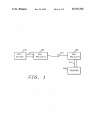
,_ FIG. 1 shows a block diagram of the concepts of the
system of the present invention;
mission capability available on the local and remote
computer systems. A still further need is for such a
system that transmits the data in a standard computer
?le format, such as ASCII, rather than converting the
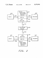
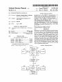
FIG. 2 shows a block diagram of the system of the
present invention being used to print data on a remote
data into a graphical image format. The present inven
Peripheral Device;
tion meets these needs.
printer by‘ using a FAX section of a Multi-Function
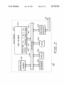
FIG. 3 shows a block diagram of the host computer
system of FIG. 2;
SUMMARY OF THE INVENTION
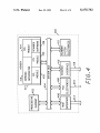
FIG. 4 shows a block diagram of the Multi-Func
It is an aspect of the present invention to allow re 65 tional Peripheral Device of FIG. 2, which includes the
present invention;
mote printing of a ?le.
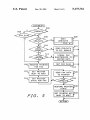
FIG. 5 shows a ?owchart of the top level of the
It is another aspect of the invention to provide such
software of the present invention; and
remote printing without requiring user intervention.
3
5,175,762
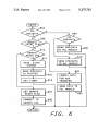
FIG. 6 shows a ?owchart of the host data/command
processing software of the present‘invention.
DESCRIPTION OF THE PREFERRED '
EMBODIMENT
The following description is of the best presently
contemplated mode of carrying out the present inven
tion. This description is not to be taken in a‘limiting
sense but is made merely for the purpose of describing
the general principles of the invention. The scope of the
invention should be determined by referencing the ap
pended claims.
FIG. 1 shows-a block diagram depicting the concept
4
FIG. 3 shows a block diagram of the host computer
system 202 of FIG. 2, which is typical of host computer
systems. The only requirement of a host system is that it
have a parallel or serial interface to a printer. Referring
now to FIG. 3, the host system 202 contains a processor
302 which is connected to the other components of the
system over a system bus 304. A keyboard 306 allows a
user of the host system 202 to enter information into the
system. A display 308 allows information to be pres
ented to the user of the host system 202. A disk 310 is
used to store software and data for the host system 202
and a peripheral interface 324 is used to communicate
over a bus 214 to the Multi-Functional Peripheral De
now to FIG. 1, a host system 102 is connected over a
vice 204 containing the switch of the present invention.
The peripheral interface 324 may be a serial interface
bus 110 to a FAX facility 104. The FAX facility 104 is
such as RS/232, or a parallel interface such as the Cen
connected via a telephone line 112 to a remote FAX
tronics parallel printer interface.
of the present invention and its environment. Referring
A memory 312 contains user software 314 and an
operating system 316. Printer Command Language
108. The host system 102 sends data over the bus 110 to
the local FAX facility 104. This data contains a com 20 (PCL) driver software 318 is used by the user software
314 to communicate to the printer 206 through the
mand that causes the FAX facility 104 to connect, via
facility 106 which is connected via bus 114 to a printer
switch 230 of the present invention. A Scanner Com
the telephone line 112, to the remote FAX facility 106.
mand Language (SCL) driver module 320 is used to
After the connection has been made, any data sent by
the host system 102 is transferred over the telephone 25 communicate to a scanner device within the Multi
Functional Peripheral Device 204. A FAX Command
line 112 to the remote FAX facility 106, which then
Language (FCL) driver module 322 is used by the user
sends the data to the printer 108 where the data is
software 314 to control all FAX functions within the
printed. Each time data is received by the local FAX
Multi-Functional Peripheral Device 204.
facility 104, it sets a timer. If the timer expires, the local
FIG. 4 shows a block diagram of the Multi-Func
FAX facility 104 assumes that the host system 102 has 30
tional Peripheral Device 204, which contains the system
completed printing and disconnects from the remote
of the present invention.’ Referring now to FIG. 4, the
FAX facility 106.
Multi-Functional Peripheral Device 204 contains a pro
FIG. _2 shows a block diagram wherein the present
cessor 402 which communicates to other elements of
invention uses a pair of Multi-Functional Peripheral
_ Devices to print remotely. Referring now to FIG.'2, a 35 the system over a system bus 404. A host system inter
face 406 is used to communicate with the host system
host system 202 is connected via a bus 214 to a local
202 over the bus 214. FAX electronics 408 are used to
Multi-Functional Peripheral Device 204 which contains
communicate to the remote FAX section 234 (FIG. 2)
a switch 230 and a FAX section 232. A remote Multi
via the telephone system 208 (FIG. 2) over the bus 218.
Functional Peripheral Device 210 is connected via
wires 220 to a telephone system 208. The telephone 40 A printer interface 410 is used to send data to the printer
206 over the bus 216. Scanner system electronics 412
system 208 is connected via wires 218 to the FAX sec
are used with a data scanning device which may also be
tion 232 of the local Multi-Functional Peripheral De
part of the Multi-Functional Peripheral Device 204. A
vice 204. The switch 230 is also connected via a bus 216
memory 414 contains a command interpreter 416 which
to a local printer 206. The switch 232 allows the host
system 202 to share the printer 206 with the FAX sec 45 routes PCL. FCL, and SCL commands between the
PCL (318), FCL (322), and SCL (320) drivers in FIG. 3
tion 232. A remote FAX section 234, within the remote
and the PCL (422), FCL (420), and SCL (424) modules
Multi-Functional Peripheral Device 210 performs the
of FIG. 4. The PCL, FCL, and SCL modules within the
same function as the local FAX section 232. The FAX
Multi-Functional Peripheral Device 204 control the
section 232 calls the FAX section 234 when the host
system 202 sends a remote print command over the bus 50 printer interface 410, the FAX electronics 408 and the‘
scanner system electronics 412, respectively. The com
214. When the remote FAX section 234 receives a call
mand interpreter 416 will be described below with re
from the local FAX section 232, it connects to the re
spect to FIGS. 5 and 6. An FCL module 420 is used to
mote printer 212 and recon?gures the printer 212 to
process commands sent by the FCL driver module 322
allow it to receive data from the host 202. When the
host system 202 sends printer data to the Multi-Func 55 (FIG. 3) in order to perform FAX related functions,
including receiving and printing remote data and FAX
tional Peripheral Device 204, the data is routed to the
messages on the shared printer 206. The FCL module
FAX section 232 which sends it to the remote FAX
420 sends commands and status to the command inter
. section 234. The remote FAX section 234 then sends the
preter 416 which processes those commands and sends
data to the printer 212 where it is printed.
A switch 228 within the remote Multi-Functional 60 them to the host system 202. The FCL module 420,
when receiving remote print data or a FAX, also sends
Peripheral Device 210 monitors all commands sent
data directly to a PCL module 422. The PCL module
from a remote host system 224 to the remote printer 212
422 receives commands and data from the command
in order to keep a copy of the printer state within RAM
interpreter and the FCL module 420, and passes those
contained in the device 210. Therefore, after the remote
print is complete, the switch 228 uses its copy of the 65 commands through the printer interface 410 to the
printer 206 (FIG. 2). An SCL module 424 receives
printer 212 state to place the printer 212 back into the
scanner command language commands from the SCL
state expected by the host system 224. In the same man
driver module 320 (FIG. 3) and passes those commands
ner, host2 224 can print data onprinter 206.
5
5,175,762
6
.If PCL commands or data were received, block 602
transfers to block 606 which determines whether the
to scanner system software 426 which interfaces to the
scanner system electronics 412.
remote print flag is set. If the remote print flag is set,
FIGS. 5 and 6 show ?owcharts of the software of the
command interpreter 416 of FIG. 4. This software is
block 606 transfers to block 620 which formats the data
for transmission to the remote FAX unit, and block 622
sends the data to the FCL module for transmission to
used to perform the remote printing and switch func- -
tions of the present invention, in conjunction with hard
ware described by the block diagram of FIG. 4. Refer
the remote FAX unit where it will be printed. Control
then returns to FIG. 5.
ring now to FIGS. 5 and 6, this ?owchart is entered
when an interrupt occurs. The interrupt indicates that a
command or data has arrived from either the host sys
tem or the FAX section of the Multi-Functional Periph
eral Device. After entry, block 502 determines whether
a timeout has occurred. A timeout will occur when the
If the remote print flag is not set, control goes to
block 612 which examines the PCL command/data to
determine if a remote print command has been received.
Table 1 shows an example of a remote print command,
which is an escape sequence sent before the data is sent.
In Table l , 9999999999 represents the telephone num
ber of the remote printer. If a remote print command
has been received, block 612 transfers to block 624
which sets the remote print flag, and block 626 uses the
telephone number in the remote print command to dial
the remote FAX and establish communication for the
host system has completed using the printer. If a time
out has occurred, block 502 transfers to block 504
which determines if the FAX is waiting to print. If the
FAX is waiting to print, block 504 transfers control to
block 520 to start the FAX print, otherwise, block 504
transfers to block 506. Block 506 determines whether
data or commands have been received from the host 20 remote print. After establishing communication with
the remote FAX, block 626 then returns to FIG. 5 to
over the host interface 406. If data or a command has
wait for data to be sent.
been received from the host, block 506 transfers to
If the command or data received from the host was
block 508 which calls FIG. 6-to process the data or
not a remote print command, it is assumed that the
command from the host before returning from the inter
rupt.
_
25 command or data is to be sent to the local printer, so
If a command or data has not been received from the
host, block 506 transfers to block 510 which determines
whether a print request has been received from the
FAX section of the Multi-Functional Peripheral De
vice. If a FAX print request has not been received, then
a command or data has been received from the FAX
section, so block 510 transfers to block 512 to send the
command or data to the FCL module for processing. If
a FAX print request has been received from the FAX
block 6712 transfer to block 614 which saves any change
in the printer state in a buffer. Block 616 then sends the
commands or data to the PCL module for processing,
and block 618 sets a timer indicating that the host is
using the printer. This timer is always set to a new value
when new commands or data are received for the
printer. Therefore, after the host has completed using
the printer, the timer will time for a full ?ve to ten
seconds before the FAX will be allowed to use the
printer. This provides sufficient time for the host to
section, block 510 transfers to block 514 which deter
re-address the printer if more printing is to be done.
mines if time has expired on the timer. If time has not
After setting the timer value, or after sending com
expired, the host is still printing, so block 514 transfers
mands
or data to the FCL or SCL modules, FIG. 6
to block 516 which signals the FAX electronics 408 to
‘
buffer the incoming FAX data. Then block 518 sets the 40 returns to FIG. 5.
Facsimile
communication
using
CCITT
Group
3
FAX flag to indicate that the FAX is waiting to print.
protocol consists of ?ve separate and consecutive pha
If the timer has expired, block 514 transfers to block
ses, as described in CCITT Terminal Equipment and
520 which reserves the printer for the FAX, and block
Protocols for Telematic Services, Volume VII-Fascicle
522 sets a busy, signal in interface 214 to indicate to the
host that the printer is busy. Block 524 sends commands 45 VII.3, Recommendation 7130, IXth Plenary Assembly,
Melbourne, 14-25 November 1988, published in Geneva.
to the printer to set the printer state to allow a FAX
1989: phase A includes call set-up, dialing, answering,
print, and block 526 sends the ?rst FAX data to the
and establishing a connection; phase B includes pre
printer. Block 528 determines if all FAX data has been
sent, and if not, block 528 transfers back to block 526 to
send more data. After all FAX data has been sent, block
528 transfers to block 530 which sends commands to the '
printer to restore the printer state, and then block 532
removes the busy signal from interface 214 before re
turning from the interrupt.
qmessage procedure for identifying and selecting fea
tures such as ?ne mode, non-standard features (NSF),
etc.; phase C includes data transmission; phase D in
cludes post-message procedures including end-of-page,
page con?rmation, and multi-document messages; and
phase B includes call release (hang up). In the present
invention, phases A and B will follow the normal FAX
FIG. 6 shows a flowchart of the host data command 55
protocol. The NSF command exchange in phase B will
processing module called by block 508 (FIG. 5). Refer
ring now to FIG. 6, after entry, block 602 determines
whether printer command language commands or data
were received. If not, block 602 transfers to block 604
which determines whether FAX command language
commands or data were received. If FAX command
language commands or data were received from the
establish the use of the NSF for remote printing. A code
in the NSF ?eld will indicate that the receiver is capable
of remote printing, and the sender will send a CCITT
NSS command indicating that remote printing will be
performed.
Phase C will then send the data in the computer stan
dard format, typically ASCII, and the receiver will
print the data on its attached printer thus providing
host, block 604 transfers to block 608 which sends the
command or data to the FCL module for processing.
faster transmission and higher print quality. This data
If FCL command/data information was not received, 65 will comprise:
the system assumes that the command/data is for the
SCL module, and control goes to block 610 to send the
The number of packets to be sent
command or data to the SCL module for processing.
1)
5,175,762
7
8
codes, printable character codes and graphical
-continued
codes into a printed document; and,
Number of bytes per packet
second facsimile means, compatible with said ?rst
Packet one. followed by a Z-byte checksum
Packet two, followed by a Z-byte checksum
facsimile means, connected to said telephone com
munication system and connected directly to said
remote printer means without an intervening com
n)
puter,
for receiving and transmitting facsimile data via
said telephone communication system, and
Last packet, followed‘ by a Z-byte checksum.
Phase D is entered automatically when the proper 10
for receiving and detecting said remote printer com
mand from said ?rst facsimile means, and
- number of packets have'been sent and received. Phase
D will be performed the same as for other normal FAX
for receiving said electronic ?le from said ?rst
facsimile means, and
transmissions, and phase E will hang up in the same
for transmitting said electronic ?le directly to said
manner as other FAX transmissions.
remote printer means, without an intervening
The state information for a printer includes print
resolution, such as 300 dots per inch; page orientation,
such as portrait or landscape; paper margins; selected
fonts; and page size. Other parameters may also be
included in the printer state depending upon the type of
computer, as said printer commands, control
codes, printable character codes and graphical
codes, whenever said second facsimile means
detects said remote printer command, so that
said remote printer means prints a document in
accordance with said electronic ?le.
2. A system as in claim 1 further comprising:
means for saving and restoring a printer state when
printer being used. Different state information might be
needed for other peripheral devices. For example, a disk
would have selected read/write head and current cylin
der as state information.
ever said second facsimile means detects said re
Having thus described a presently preferred embodi
mote printer command.
ment of the present invention, it will now be appreci 25
3. A method for remotely printing an electronic ?le
ated that the objects of the invention have been fully
from an electronic source, said electronic ?le compris
achieved, and it will be understood by those skilled in
ing printer commands, control codes, printable charac
the art that many changes in construction and circuitry
ter codes, and graphical codes, the method comprising
and widely differing embodiments and applications of
the steps of:
transmitting a remote printer command and said elec
the invention will suggest themselves without departing
from the spirit and scope of the present invention. The
tronic ?le from said electronic source to a ?rst
disclosures and the description herein are intended to be
illustrative and are not in any sense limiting of the in
facsimile system, said first facsimile system capable
vention, more preferably de?ned in scope by the fol 35
lowing claims.
TABLE l-Remote Print Command
i
What is claimed is:
1. A remote printing system for printing an electronic
?rst facsimile system to a second facsimile system,
said second facsimile system capable of receiving
and sending facsimile data;
receiving via said telephone communication system
?le hat is transmitted through a telephone communica
tion system, said electronic ?le comprising printer com
mands, control codes, printable character codes, and
graphical codes, said remote printing system compris
said remote printer command from said electronic
source by said second facsimile system;
detecting said remote printer command from said
electronic source by said second facsimile system;
ing:
electronic source means for transmitting a remote
printer command and said electronic ?le;
receiving via said telephone communication system
?rst facsimile means, connected to said electronic
said electronic ?le from said electronic source by
said second facsimile system;
transmitting said electronic ?le as said printer com
source means and connected to said telephone
communication system;
for receiving and transmitting facsimile images via
said telephone communication system, and
for receiving and detecting said remote printer
mands, control codes, printable character codes
- and graphical codes from said second facsimile
system directly to a printer, without an intervening
computer, whenever said second facsimile system
detects said remote printer command;
command from said electronic source means,
and
for receiving said electronic ?le from said elec
tronic source means, and
detecting said remote printer command by said ?rst
facsimile system;
transmitting via a telephone communication system
said remote printer command and said electronic
?le as said printer commands, control codes ,print
able character codes, and graphical codes from said
Esc‘{4I9999999999I<cr>/* Enter remote Printing
Mode */
of receiving and sending facsimile data;
receiving said electronic ?le by said printer; and,
translating said printer commands, control codes,
printable character codes and graphical codes by
t
for transmitting said remote. printer command and
said electronic ?le as said printer commands,
control codes, printable character codes and
graphical codes via said telephone communica
said printer into a printed document.
4. A method as in claim 3 further comprising:
saving a printer state whenever said second facsimile
means detects said remote printer command; and
tion system, whenever said ?rst facsimile means
detects said remote printer command;
remote printer means for receiving said electronic ?le
and for translating said printer commands, control
65
restoring said printer state whenever said printer
completes printing said printed document.
it
it
ll
it
it
'