1
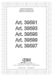
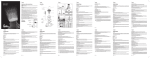
Fig. 1
Fig. 2
Fig. 5
Fig. 4
Fig. 7
Ch. 2,5 mm
Fig. 3
Ch. 27 mm
Fig. 6
Fig. 1
A
ISTRUZIONI DI MONTAGGIO, D’USO E MANUTENZIONE
- Prima dell’installazione e messa in funzione.
Attenzione! I tubi d’alimentazione devono essere sciacquati con cura prima dell’installazione del miscelatore, in modo
che non rimangano trucioli, residui di saldatura o canapa, o altre impurità all’interno dei tubi. Attraverso
tubazioni non sciacquate a fondo o attraverso la rete idrica generale, nel miscelatore possono entrare
corpi estranei in grado di danneggiare le guarnizioni/guarnizioni ad anello. Generalmente si consiglia di
installare un filtro sul raccordo principale dell’acqua. Prima della messa in funzione, svitare l’aeratore e
sciacquare molto bene.
Sostituzione della cartuccia (Fig. 1)
Prima di sostituire la cartuccia, accertarsi che il raccordo dell’acqua sia chiuso. Svitare la vite di fissaggio (A) utilizzando una chiave a brugola, estrarre quindi la maniglia (B) sfilandola dalla cartuccia (F). Sollevare la ghiera copricartuccia
(C) facendo leva (come in figura) tramite l’apposita scanalatura di riferimento. Allontanare l’anello indicatore (D), svitare
la ghiera di fissaggio (E) e togliere la cartuccia (F) dal corpo del miscelatore (G). Infine introdurre la nuova cartuccia, accertandosi che le due spine di centraggio siano nella loro sede e che le guarnizioni siano correttamente posizionate.
Montaggio del monocomando (Fig. 2 - Fig. 3)
Prima di inserire il monocomando nel foro del lavello assicurarsi che la guarnizione di base sia ben posizionata nella
propria sede e che i flessibili di alimentazione siano ben avvitati al corpo del rubinetto. Sistemare il monocomando
sul foro del lavello orientando la bocca di erogazione verso la vasca del lavello. Inserire quindi il kit di fissaggio nella
sequenza indicata e rispettivamente:
· la guarnizione sagomata e la flangia nel caso si installi il monocomando su un lavello di spessore 3-4 cm;
· la guarnizione sagomata, la flangia triangolare in plastica e la flangia nel caso si installi il monocomando su un lavello
in acciaio inox di spessore 1-2 mm.
Serrare a fondo l’apposito tirante o dado filettato. Nel caso il rubinetto sia un monocomando con doccetta estraibile
collegare il flessibile al tubetto di uscita interponendo la guarnizione di tenuta. Fissare il contrappeso di piombo sul
tubo del flessibile ad una distanza di 40 cm dall’attacco del tubetto di uscita.Procedere al collegamento dei flessibili
alla rete di alimentazione. Nel caso il rubinetto sia un monocomando con doccetta estraibile avvitare la doccetta al tubo
flessibile interponendo la guarnizione di tenuta e verificare che il flessibile scorra in maniera lineare.
B
Ch.2.5 mm
C
D
Ch.28mm
E
F
G
Fig. 2
40 MAX
Ø33.5
1 - 2 mm
Fig. 3
40 MAX
Ø33.5
1 - 2 mm
40cm
misure in mm - measures in mm - dimensions en mm - Maß im mm - medidas en el mm
DIRECTIONS FOR ASSEMBLY, USE AND MAINTENANCE
- Before installation and setting to work
Attention! The feeding pipes have to be rinsed thoroughly before the installation of the mixer, so that no shavings,
welding or hemp residual or other dirt can be found in the pipes. Foreign bodies can enter the mixer through
the rinsed pipes or the general water plant and could damage the washers/ring washers. Normally, it is
recommended to install a filter on the main water union. Before the setting to work, unscrew the aerator
and rinse it very well.
- Replacement of the cartridge (Fig. 1)
Before carrying out this operation make sure that water connection is closed. Unscrew the fastening screw (A) using
an Allen wrench, take out the handle (B), removing it from the cartridge (F). Lift the finishing ring nut (C) using the
reference notch (as indicated in the figure). Remove the indicator ring (D), unscrew the fixing ring nut (E) and take the
cartridge (F) out form the mixer body (G). Then put the new cartridge, verifying that the two centering pins enter into
the respective seats and that gaskets are well positioned.
- Assembling instructions for the single-lever mixer (Fig. 2 - Fig. 3)
Before inserting the single lever group in the hole of the sink, make sure that the base gasket is properly positioned in
its seat and that the flexible hoses are well tightened to the body of the tap. Place the single lever group in the hole of
the sink, orienting the spout toward the sink tank. Insert the fixing kit with the indicated sequence, and respectively:
· the shaped gasket and flange in case the single lever group is installed on a sink having thickness of 3-4 cm;
· the shaped gasket, the triangular plastic flange and the flange in case of a stainless steel sink having thickness of
1-2 mm.
Tighten well the tie rod or the threaded nut. In case the tap is a single lever group with extractable shower, connect the
flexible hose to the outlet pipe interposing the gasket. Fix the lead counterweight to the flexible hose at a distance of
approx. 40 cm from the connection to the outlet pipe. Proceed connecting the flexible hoses to the plumbing. In case
the tap is a single lever group with extractable shower, tighten the shower to the hose interposing the gasket and confirm the hose can slide smoothly through the passage hole.
INSTRUCTIONS DE MONTAGE, D’EMPLOI ET D’ENTRETIEN
- Avant l’installation et la mise en fonction.
Attention! Les tubes d’alimentation doivent être rincés avec soin avant l’installation du mélangeur, de façon qu’il ne
reste pas de riblons, de restes de soudure ou de chanvre, ou d’autres saletés à l’intérieur des tubes. A
travers les tuyauteries qui ne sont pas bien rincées ou à travers l’installation hydrique générale, des corps
étrangers peuvent entrer dans le mélangeur et abîmer les joints/ les joints à anneau. Généralement nous
conseillons d’installer un filtre sur le joint principal de l’eau. Avant la mise en fonction, dévisser l’aérateur
et bien rincer.