1
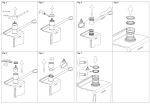
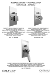
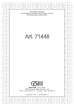
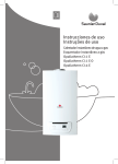
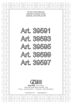
Instructions de montage du mélangeur mono-commande (Fig.
1-2-3)
Avant d’insérer le monocommande dans le trou de l’évier, il faut
s’assurer que le joint de base est bien placé dans son emplacement
et que les flexibles d’alimentation sont bien vissés au corps du robinet.
Il faut placer le monocommande sur le trou de l’évier en orientant la
bouche de distribution vers le bac de l’évier. Insérer donc le kit de
fixage dans la séquence indiquée et respectivement:
· le joint façonné et la bride si on installe le monocommande sur un
évier d’une épaisseur de 3-4 cm;
· le joint façonné, la bride triangulaire en plastique et la bride dans le
cas d’un évier en acier inox d’une épaisseur de 1-2 mm.
Serrer à fond le tirant ou l’écrou fileté. Si le robinet est un
monocommande avec la douchette détachable, il faut relier le flexible
au tuyau de sortie en interposant le joint d’étanchéité. Il faut fixer le
contrepoids de plomb sur le tuyau du flexible à une distance de 400
mm du raccord du tuyau de sortie, il faut visser la douchette au tuyau
flexible en interposant le joint d’étanchéité et il faut vérifier que le
flexible glisse de façon linéaire. Procéder à la liaison des flexibles au
réseau d’alimentation.
Substitution de la cartouche (Fig. 4)
Avant d'effectuer la substitution de la cartouche, vérifier que la
connexion de l'eau est fermée.
Dévisser la vis de fixation (A) utilisant une clé à griffe, extraire en
suite la poignée (B) en la soulevant de la cartouche (F). Soulever la
virole de finition (C) en utilisant (comme indiqué en la figure) la rainure
de référence. Quitter la bague d'indication (D), dévisser la virole
de fixation (E) et enlever la cartouche (F) du corps de mitigeur (G).
Introduire enfin la cartouche nouvelle, en vérifiant que les deux pivots
de centrage entrent dans les sièges respectifs et que les garnitures
sont bien positionnées.
MONTAGE-, WARTUNGS- UND GEBRAUCHSANWEISUNGEN
Vor der Installation und Inbetriebnahme
Achtung! Die Zuleitungsrohre müssen vor dem Installieren der
Armatur gründlich durchgespült werden, damit keine Späne, Löt
- Hanfreste oder andere Unreinheiten zurückbleiben. Bei nicht
durchgespülten Rohrleitungen oder durch die Wasseranlage
allgemein können Fremdkörper in die Armatur geraten und die
Dichtungsscheiben/Dichtungen beschädigen und/oder die Kartuschen
und die Oberteile beschädigen können. Um eine lange Dauer
dem Produkt zu gewährleisten, installieren Sie die Wasserhahne
Unterwaschbecken mit einem Filter, das regelmäßig gereinigt werden
muss. Vor Inbetriebnahme der Armatur den Perlator abschrauben und
gut durchspülen.
Montageanleitung Einhebelmischer (Abb. 1-2-3)
Bevor Sie die Einhebel-Mischbatterie in die Bohrung des Spülbeckens
einführen, vergewissern Sie sich, dass die Basisdichtung perfekt in
ihrem Sitz positioniert ist und das die Versorgungsschläuche gut am
Armaturenkörper festgeschraubt sind. Die Einhebel-Mischbatterie
auf der Bohrung des Spülbeckens positionieren, wobei der Auslauf in
Richtung des Spülbeckens orientiert sein muß.
Anschließend den Befestigungssatz in der angegebenen Reihenfolge
einführen, und zwar:
· die
geformte Dichtung und den Flansch, falls man die EinhebelMischbatterie auf einem Spülbecken mit einer Dicke von 3-4 cm
installiert;
·d
ie geformte Dichtung, den dreieckigen Kunststoffflansch und den
Flansch, falls man diese auf einem Inoxstahl-Spülbecken mit einer
Dicke von 1-2 mm installiert.
Die eigens dafür vorgesehene Zugstange oder die gestrehlte
Schraubenmutter bis zum Anschlag festziehen. Das Gegengewicht
aus Blei in einem Abstand von 400 mm vom Anschluss des
Ausgangsrohr an dem Schlauch fixieren, schließt man Den Schlauch an dem
Rohrausgang an, wobei man die Dichtung dazwischen einlegt. Dann schließt
man die Schläuche an das Versorgungsnetz an. Falls es sich bei der Armatur
um eine Einhebel-Mischbatterie mit herausziehbarer Handbrause handelt,
schraubt man die Handbrause an dem Schlauch fest, wobei man die Dichtung
dazwischen einlegt und sich vergewissert, dass der Schlauch linear verläuft.
Austauschen der kartusche (Abb. 4)
Bevor man die Kartusche austauscht muß man sich vergewissern, dass das
Wasserversorgungsnetz geschlossen ist.
Die Befestigungsschraube (A) unter Einsatz eines Sechskantschlüssel
losschrauben, dann den Griff (B) herausziehen, indem man ihn von der
Kartusche (F) abzieht. Die Nutmutter, welche die Kartusche (C) abdeckt,
entfernen, wobei man Druck auf die eigens dafür vorgesehene Bezugsrille
(entsprechend der Abbildung) ausübt. Den Anzeigering (D) entfernen, die
Befestigungsnutmutter (E) losschrauben und die neue Kartusche (F) vom
Körper der Mischbatterie (G) entfernen. Schließlich eine neue Kartusche
einsetzen, wobei man sich vergewissert, dass sich die beiden Zentrierstifte in
ihrem Sitz befinden und das die Dichtungen korrekt positioniert sind.
INSTRUCCIONES DE MONTAJE, DE USO Y MANUTENCION
Antes de la instalación y la puesta en función
¡Cuidado! Los tubos de alimentación tienen que ser enjuagados a fondo
antes de la instalación del mezclador de manera que no queden virutas,
residuos de soldadura o cáñamo u otras impurezas en los tubos. A través
de tubería no bien enjuagada o de la red hídrica en general, en el mezclador
pueden entrar cuerpos extraños capaces de dañar los empaques/anillos de
cierre y/o cartuchos/ monturas. Para garantizar un plazo largo de vida del
producto, instalen las llaves de paso con filtro debajo del lavabo y límpienlas
periódicamente. Antes de la puesta en función, destornillen el regulador de
flujo y enjuaguen muy bien.
Instalación de monomando (Fig. 1-2-3)
Antes de introducir el monomando en el agujero del fregadero, asegúrense
que la junta de base esté bien posicionada en su propio asiento y que
los flexibles de alimentación estén bien atornillados al cuerpo del grifo.
Posicionen el monomando sobre el agujero del fregadero, orientando el caño
de erogación hacia la cubeta del fregadero. Introduzcan el juego de fijación
según la secuencia indicada y respectivamente:
· la junta moldurada y la brida en el caso de que se instale el monomando
sobre un fregadero de 3-4 cm de espesor;
· la junta moldurada, la brida triangular de plástico y la brida en el caso de
que se instale el monomando sobre un fregadero de acero inoxidable de 1-2
mm de espesor.
Rosquen hasta el fondo el tirante o la tuerca roscada. En el caso de que el
grifo sea un monomando con ducha-teléfono extraíble, conecten el flexible al
tubo de salida interponiendo la junta de cierre. Fijen el contrapeso de plomo
sobre el tubo del flexible a una distancia de 400 mm de la conexión del tubo
de salida, atorníllen la ducha-teléfono al tubo flexible, interponiendo la junta
de cierre y verifiquen que el flexible deslice de manera lineal. Efectúen la
conexión de los flexibles a la red de alimentación.
Sustitución del cartucho (Fig. 4)
Antes de sustituir el cartucho, asegúrense que la conexión del agua esté
cerrada.
Destornillen el tornillo de fijación (A) utilizando una llave de allén, extraigan
la maneta (B) sacándola del cartucho (F). Levanten la virola cubre-cartucho
(C) utilizando la ranura de referencia (como indicado en la figura). Quiten el
anillo indicador (D), destornillen la virola de fijación (E) y extraigan el cartucho
(F) del cuerpo del mezclador (G). Finalmente introduzcan el cartucho nuevo,
asegurándose que las dos clavijas de centraje se encuentren en su asiento y
que las juntas estén posicionadas correctamente.
ET 37224 - R1
PROGRAMMA MISCELAZIONE CUCINA
KITCHEN MIXING PROGRAM
PROGRAMME DU MITIGEUR POUR LA CUISINE
KÜCHEN-MISCHUNGSPROGRAMM
PROGRAMA MEZCLADORES COCINA
OZONE
Art. 15251
Art. 15257
Gessi SpA - Parco Gessi
13037 Serravalle Sesia (Vercelli) - Italy
Phone +39 0163 454111 - Facsimile +39 0163 459273
www.gessi.com - [email protected]
Fig. 1
Fig. 2
Fig. 3
ISTRUZIONI DI MONTAGGIO, D’USO E MANUTENZIONE
Prima dell’installazione e messa in funzione
Attenzione! I tubi d’alimentazione devono essere sciacquati con cura prima dell’installazione del miscelatore, in modo
che non rimangano trucioli, residui di saldatura o canapa, o altre impurità all’interno dei tubi. Attraverso tubazioni non
sciacquate a fondo o attraverso la rete idrica generale, nel miscelatore possono entrare corpi estranei in grado di
danneggiare le guarnizioni/guarnizioni ad anello e/o cartucce/vitoni. Al fine di garantire una lunga durata del prodotto
installare i rubinetti sottolavabo dotati di filtro, da pulire periodicamente. Prima della messa in funzione, svitare l’aeratore
e sciacquare molto bene.
Montaggio del monocomando (Fig. 1-2-3)
Prima di inserire il monocomando nel foro del lavello assicurarsi che la guarnizione di base sia ben posizionata nella
propria sede e che i flessibili di alimentazione siano ben avvitati al corpo del rubinetto. Sistemare il monocomando
sul foro del lavello orientando la bocca di erogazione verso la vasca del lavello. Inserire quindi il Kit di fissaggio nella
sequenza indicata e rispettivamente:
· la guarnizione sagomata e la flangia nel caso si installi il monocomando su un lavello di spessore 3-4 cm;
· la guarnizione sagomata, la flangia triangolare in plastica e la flangia nel caso si installi il monocomando su un lavello
in acciaio inox di spessore 1-2 mm.
Serrare a fondo l’apposito tirante o dado filettato. Nel caso il rubinetto sia un monocomando con doccetta estraibile
collegare il flessibile al tubetto di uscita interponendo la guarnizione di tenuta. Fissare il contrappeso di piombo sul
tubo del flessibile ad una distanza di 400 mm dall’attacco del tubetto di uscita, avvitare la doccetta al tubo flessibile
interponendo la guarnizione di tenuta e verificare che il flessibile scorra in maniera lineare. Procedere al collegamento
dei flessibili alla rete di alimentazione.
Sostituzione della cartuccia (Fig. 4)
Prima di sostituire la cartuccia, accertarsi che il raccordo dell’acqua sia chiuso.
Svitare la vite di fissaggio (A) utilizzando una chiave a brugola, estrarre quindi la maniglia (B) sfilandola dalla cartuccia
(F). Sollevare la ghiera copricartuccia (C) facendo leva (come in figura) tramite l’apposita scanalatura di riferimento.
Allontanare l’anello indicatore (D), svitare la ghiera di fissaggio (E) e togliere la cartuccia (F) dal corpo del miscelatore
(G). Infine introdurre la nuova cartuccia, accertandosi che le due spine di centraggio siano nella loro sede e che le
guarnizioni siano correttamente posizionate.
1-2 mm
45mm
Ø33.5
40max
400 mm
19mm
Fig. 2
Fig. 1
Fig. 3
1-2 mm
Ø33.5
40max
11mm
Fig. 4
19mm
266
220
B
266
223
2,5mm
236
A
C
Ø50
15°
144
217
Ø50 15°
40 MAX
D
139
40max
27mm
E
350
350
F
G
G3/8"
G3/8"
dimensioni in mm - measures in mm - dimensions en mm - Maß im mm - medidas en mm
DIRECTIONS FOR ASSEMBLY, USE AND MAINTENANCE
Before installation and setting to work
Attention! The feeding pipes have to be rinsed thoroughly before the installation of the mixer, so that no shavings,
welding or hemp residual or other dirt can be found in the pipes. Foreign bodies can enter the mixer through the rinsed
pipes or the general water plant and could damage the washers/ring washers and/or cartridges/headvalves. In order
to guarantee a long use of the product, install the angle valve equipped with filter and clean them regularly. Before the
setting to work, unscrew the aerator and rinse it very well.
Assembling instructions for the single-lever mixer (Fig 1-2-3)
Before inserting the single lever group in the hole of the sink, make sure that the base gasket is properly positioned in
its seat and that the flexible hoses are well tightened to the body of the tap.
Place the single lever group in the hole of the sink, orienting the spout toward the sink tank. Insert the fixing kit with the
indicated sequence, and respectively:
· the shaped gasket and flange in case the single lever group is installed on a sink having thickness of 3-4 cm;
· the shaped gasket, the triangular plastic flange and the flange in case of a stainless steel sink having thickness of 1-2
mm.
Tighten well the tie rod or the threaded nut. In case the tap is a single lever group with extractable shower, connect
the flexible hose to the outlet pipe interposing the gasket. Fix the lead counterweight to the flexible hose at a distance
of approx. 400 mm from the connection to the outlet pipe, tighten the shower to the hose interposing the gasket and
confirm the hose can slide smoothly through the passage hole. Proceed connecting the flexible hoses to the plumbing.
Cartridge replacement (Fig 4)
Before carrying out this operation make sure that water supply is turned off.
Unscrew the fastening screw (A) using an Allen key, remove the handle (B) from the cartridge (F). Lift the finishing ring
nut (C) using the reference notch (as shown in the figure). Remove the indicator ring (D), unscrew the fixing ring nut
(E) and take the cartridge (F) out from the mixer body (G). Put the new cartridge into the body checking that the two
centering pins enter into the respective seats and that gaskets are well positioned.
INSTRUCTIONS DE MONTAGE, D’EMPLOI ET D’ENTRETIEN
Avant l’installation et la mise en fonction
Attention! Les tubes d’alimentation doivent être rincés avec soin avant l’installation du mélangeur, de façon qu’il ne
reste pas de riblons, de restes de soudure ou de chanvre, ou d’autres saletés à l’intérieur des tubes. A travers les
tuyauteries qui ne sont pas bien rincées ou à travers l’installation hydrique générale, des corps étrangers peuvent entrer
dans le mélangeur et abîmer les joints/ les joints à anneau et/ou cartouches/têtes. Dans le but de garantir une longue
durée du produit, instaure les robinets sous lavabo munis du filtre et nettoie-les régulièrement. Avant la mise en fonction,
dévisser l’aérateur et bien rincer.