1
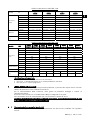
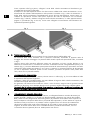
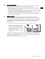
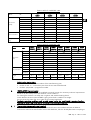
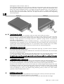
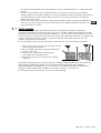
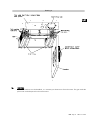
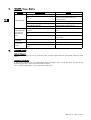
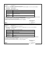
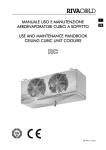
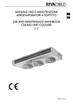
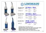
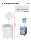
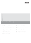
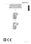
MANUALE USO E MANUTENZIONE
AEROEVAPORATORI A SOFFITTO
USE AND MAINTENANCE HANDBOOK
CEILING UNIT COOLERS
RDF
RDF REV. 01 04/06
I
UK
RDF Pag. 2
REV. 01 04/06
ITALIANO
SOMMARIO
1. Scopo del manuale
2. Norme di uso generale
3. Modo di identificazione della macchina
4. Installazione
5. Collegamento frigorifero
6. Collegamento scarico condensa
7. Installazione elettrica
8. Dati tecnici
9. Manutenzione e pulizia
10.Smaltimento
11.Guasti e rimedi
12.Optional
pag. 3
pag. 3
pag. 4
pag. 5
pag. 6
pag. 6
pag. 7
pag. 10
pag. 10
pag. 11
pag. 12
pag. 12
I
1.
SCOPO DEL MANUALE
Il presente manuale ha lo scopo di aiutare l’operatore nella corretta messa in funzione
dell’evaporatore, chiarire le relative norme di sicurezza vigenti nella comunità europea ed eliminare
eventuali rischi da errati utilizzi.
2.
NORME DI USO GENERALE
• Per un utilizzo corretto e sicuro della macchina, è necessario attenersi alle prescrizioni contenute nel
presente manuale in quanto fornisce istruzioni e indicazioni circa:
9 modalità di installazione
9 uso della macchina
9 manutenzione della macchina
9 smaltimento e messa fuori servizio
• Il costruttore non risponde per danni derivanti dalla inosservanza delle note e avvertenze contenute
nel presente libretto di istruzioni.
• Leggere attentamente le etichette sulla macchina, non coprirle per nessuna ragione e sostituirle
immediatamente in caso venissero danneggiate.
• Conservare con cura il presente manuale.
• Il costruttore si riserva di aggiornare il presente libretto senza nessun preavviso.
• Gli aeroevaporatori sono realizzati per la sola refrigerazione industriale e commerciale in sede
stabile. Non sono consentiti usi diversi da quello destinato. Ogni altro uso è considerato improprio e
quindi pericoloso.
• Dopo aver tolto l’imballo assicurarsi che la macchina sia intatta in ogni sua parte, in caso contrario
rivolgersi al rivenditore.
• E’ vietato l’utilizzo della macchina in ambienti con presenza di gas infiammabile e in ambienti con
rischio di esplosione.
• Non lavare la macchina con getti d’acqua diretti o in pressione, o con sostanze nocive.
• Non usare la macchina priva di protezioni (carenatura e griglia)
• Evitare che la macchina sia esposta a fonti di calore.
• In caso di incendio usare un estintore a polvere.
• Il materiale dell’imballaggio deve essere smaltito nei termini di legge.
RDF Pag. 3
REV. 01 04/06
MODO DI IDENTIFICAZIONE DELLA MACCHINA
Tutte le macchine sono provviste di relativa etichetta di riconoscimento (la posizione è indicata in Fig.1)
in cui sono riportati i seguenti dati:
assorbimento in Watt (W)
• codice
tensione di alimentazione (Volt/Ph/Hz)
• n° motoventilatori - n° giri (RPM)
• gruppo fluido refrigerante: Gruppo 2 (*)
assorbimento in Watt (W)
• pressione PS (pressione massima di lavoro)
assorbimento in ampere (A)
tensione di alimentazione (Volt/Ph/Hz)
• temperatura TS (temperatura minima di esercizio)
• sbrinamento:
• matricola
n° resistenze
3.
I
(*) Secondo la normativa EN 378/1 appartengono al Gruppo 2 i seguenti gas :
R22,R134a,R507,R404A,R407C,R410A,R410B
Tutti gli evaporatori RDF rientrano nella categoria 0 secondo la direttiva 97/23/CE (P.E.D.)
Fig. 1
B
P
B
C
H
P+300
F
50
min 700
min 700
E
140
Etichetta di
riconoscimento
A
Dettaglio A
9
D
30
RDF versione a 3 motoventilatori con
3 staffe di fissaggio
RDF Pag. 4
REV. 01 04/06
Tabella caratteristiche modelli RDF –250
Modello
RDF
Dimensioni
(mm)
1250
2250
3250
4250
1250ED
2250ED
3250ED
4250ED
P
335
735
1135
1535
B
93,5
93,5
93,5
93.5
C
710
710
710
710
D
650
650
650
650
E
638
638
638
638
H
150
150
155
160
F
50
50
50
50
10 x 1mm – 1/2” SAE
10 x 1mm - 1/2” SAE
12 x 1mm - 1/2” SAE
12 x 1mm - 1/2” SAE
Ø entrata
Attacchi
I
Ø uscita
12 x 1 mm
12 x 1 mm
18 x 1mm
22 x 1mm
Ø scarico
1/2" gas (20mm)
1/2" gas (20mm)
1 gas (33mm)
1 gas (33mm)
Peso
vers. normale
11,5
18,0
27,0
34,0
(kg)
vers. ED
12,0
19,0
28,5
36,0
Tabella caratteristiche modelli RDF –350
Modello
RDF
23503
23507
23503ED 23507ED
P
Dimensioni
(mm)
Attacco scarico
Peso
(kg)
53503
53507
53503ED
53507ED
1020
1470
1920
2370
P1
---
510
960
960
B
173
173
173
173
C
860
860
860
860
D
800
800
800
800
E
756
756
756
756
H
241
246
251
256
F
Attacchi batteria
33507
43503
43507
33503
33503ED 33507ED 43503ED 43507ED
Ø entrata
110
110
110
110
12x1mm – 1/2” SAE
12x1 mm – 1/2” SAE
16x1 mm – 5/8” SAE
16x1 mm – 5/8” SAE
Ø uscita
22 x 1 mm
28 x 1.5mm
35 x 1.5mm
35 x 1.5mm
Ø scarico
1” gas (33mm)
1” gas (33mm)
1” gas (33mm)
1” gas (33mm)
vers.
normale
36.1
35.5
50.4
49.5
60.6
59.5
73.6
72.2
vers. ED
38.6
38.0
53.9
53.0
65.1
64.0
79.4
78.0
Identificazione della matricola:
• cifra 1 e 2 = ultime due cifre dell’anno di costruzione
• cifra 3 e 4 = settimana dell’anno in cui è stata prodotta la macchina
• cifre 5,6,7e 8 = numero progressivo
4.
INSTALLAZIONE (Note generali)
L’installazione deve essere eseguita da personale qualificato, in possesso dei requisiti tecnici necessari
stabiliti dal paese dove viene installata la macchina.
Per la movimentazione della macchina, usare guanti di protezione antitaglio o sistema di
sollevamento idoneo.
Assicurarsi che la struttura su cui andrà fissato l’RDF, sia adeguata al suo peso.
Non canalizzare l’aria dei motoventilatori per non aumentare le perdite di carico.
Condizioni particolari di funzionamento come celle troppo basse, stoccaggi eccessivi, ostacoli al getto
d’aria, possono influenzare le prestazioni dichiarate.
4. 1
Montaggio valvola termostatica (non fornita)
Dimensionare opportunamente la valvola termostaticha che dovrà essere installata con l'equilibrio
esterno.
RDF Pag. 5
REV. 01 04/06
Come riportato nella fig.3 part.A, collegare l’uscita della valvola termostatica al distributore già
corredato da connessione a flangiare.
Predisporre il tubo dell’equilibrio esterno che dovrà essere saldato sulla valvola termostatica e vicino
all'estremità del collettore dell'evaporatore nella posizione mostrata in Fig. 3 Part. B. Posizionare il
bulbo della valvola termostatica immediatamente prima del tubo dell’equilibrio esterno posto sul
collettore di aspirazione. Fissarlo nella parte superiore del tubo di aspirazione con la fascetta
metallica (Fig. 3 Part.C). Saldare sull’ingresso della valvola termostatica, un tubo opportunamente
piegato in precedenza (Fig. 3 Part D). Il tubo sarà collegato successivamente alla tubazione del
liquido dell’impianto frigorifero.
I
Fig. 2
Fig. 3
B
D
A
C
4. 2
Posizionamento a soffitto
Una volta collegata la valvola termostatica, fissare l’evaporatore al soffitto della cella.
La macchina deve essere installata solo in posizione orizzontale, utilizzando le apposite asole di
fissaggio. Gli interassi di fissaggio e la posizione delle ventole rispetto alle pareti della cella, è mostrata
in Fig.1.
Lasciare intorno alla macchina sufficiente spazio per permettere un buon ricircolo dell’aria e per
effettuare le manutenzioni in condizioni di sicurezza. La distanza minima consigliata dalla parete, è di
700mm (Fig. 1). Lasciare abbastanza spazio posteriormente ed anteriormente per permettere una facile
sostituzione della valvola termostatica e per inserire o sostituire le resistenze elettriche di sbrinamento
(se non è disponibile sufficiente spazio sul lato resistenze, prevedere un’apertura sulla parete della
cella, chiusa con un pannello mobile).
5.
COLLEGAMENTO FRIGORIFERO
Sull’uscita dell’evaporatore (tubo in basso) si dovrà inserire un sifone (Fig. 3), che verrà saldato sul tubo
di aspirazione dell’impianto frigorifero.
Collegare il tubo che precedentemente era stato saldato all’ingresso della valvola termostatica, alla
tubazione del liquido dell’impianto frigorifero.
Per garantire una buona tenuta ermetica e ridurre i rischi di rottura, eseguire tutte le giunzioni tramite
saldatura a “bicchiere”. Se il diametro dei tubi non lo consente, utilizzare dei giunti a saldare idonei.
Durante le fasi di collegamento tubazioni, fare attenzione a non forzare o modificare la posizione del
collettore in quanto si potrebbero favorire rotture.
6.
COLLEGAMENTO SCARICO CONDENSA
La tubazione per lo scarico dell’acqua di condensa, và collegata all’attacco maschio da 20mm (per
quanto riguarda i modelli a 1 e 2 ventole con diametro ø250) o da 33mm (per tutti gli altri modelli
RDF) situato sul lato collegamento elettrico/frigorifero (la pendenza minima deve essere superiore al
20%). Predisporre sulla parete della cella in prossimità dell’evaporatore, un foro attraverso il quale la
tubazione uscirà per arrivare in un pozzetto a sifone. Sigillare il foro con silicone (di caratteristiche
idonee all’uso della cella) onde evitare infiltrazioni di aria calda. In caso di cella a temperatura
negativa, la linea di scarico deve essere riscaldata durante il periodo di sbrinamento, con una
resistenza al silicone (optional) da circa 100W posta al suo interno.
RDF Pag. 6
REV. 01 04/06
7.
7. 1
INSTALLAZIONE ELETTRICA
Le operazioni di collegamento elettrico, devono essere eseguite da personale qualificato in possesso
dei requisiti tecnici necessari stabiliti dal paese dove viene installata la macchina
• Predisporre opportuni sistemi di protezione sulla linea di alimentazione ed accertarsi che la
tensione corrisponda a quella indicata sull’etichetta applicata sulla macchina (tolleranza
consentita ± 10% della tensione nominale).
• E’ obbligatorio, a termini di legge, collegare la macchina ad un efficiente impianto di messa a
terra. Si declina ogni responsabilità dall’inosservanza di tale disposizione e qualora l’impianto
elettrico a cui ci si allaccia non sia realizzato secondo le norme vigenti.
• Sull’evaporatore va installato un termostato meccanico opportunamente tarato che disabilita le
resistenze in caso di sovratemperatura. Il bulbo del termostato va posizionato nel pacco alettato
nel punto più alto dell’evaporatore.
Collegamento elettrico
Sul lato collegamento elettrico (vedi Fig. 8-9), si trova la scatola di derivazione utilizzata per il
collegamento di tutti i componenti elettrici dell’evaporatore. Per quanto riguarda i modelli RDF con
diametro ø 250,all’interno della scatola di derivazione, sono presenti due morsettiere: la morsettiera
per il collegamento di terra e la morsettiera ad innesto rapido dove collegheremo l’alimentazione dei
motoventilatori e delle resistenze. Per quanto riguarda invece i modelli con ø 350, all’interno della
scatola di derivazione, è presente una sola morsettiera ad innesto rapido dove collegheremo le
resistenze e le terre.
Per l’inserimento dei fili sulla morsettiera ad innesto rapido, seguire le seguenti istruzioni:
1- inserire a fondo un giravite sull’apposita
apertura (vicina al centro della morsettiera)
2- la lama del giravite mantiene aperta la molla
permettendo l’introduzione del conduttore
3- Inserire il conduttore con l’estremità spellata o
dotata di terminale crimpato
4- estrarre il giravite. Il conduttore è ormai fissato
in modo sicuro.
I modelli hanno motoventilatori alimentati con una tensione 230V/1Ph/50-60Hz; sui modelli /ED
sono presenti le resistenze di sbrinamento, predisposte per essere alimentate a 400V/3Ph/50-60Hz
(vedi Fig. 4-6). Volendo alimentare le resistenze con una tensione di 230V/1Ph/50-60Hz, modificare
il collegamento come mostrato in Fig. 5 - 7.
Per il passaggio dei cavi, utilizzare le aperture già predisposte.
RDF Pag. 7
REV. 01 04/06
I
Fig. 4
I
R1
R2
N
N
230V/1Ph/50-60Hz
4
3
2
1
L1
L2
N
L
400V/3Ph/50-60Hz
N
Fig. 5
R1
R2
N
Modello
Motoventilatori
Assorbimento
motoventilatori
Potenza resistenze
RDF
n x ømm
A
W
W
1250
1250ED
1 x 250
0,45
65
800
N
230V/1Ph/50-60Hz
4
3
2
1
N
L1
L
N
2250
2250ED
2 x 250
0,90
130
1650
230V/1Ph/50-60Hz
3250
3250ED
3 x 250
1,35
195
2500
RDF Pag. 8
4250
4250ED
4 x 250
1,8
260
3150
REV. 01 04/06
Fig. 6
R1
R2
M M M
R3
I
M M
R4
1 1 2 3 N N N 4 N 5
400V/3Ph/50-60Hz
"A"
L1
L2
L3
N
L
L
L0
L0
230V/1Ph/50-60Hz
N
Fig. 7
R1
R2
M M M
R3
M M
R4
1 1 2 3 N N N 4 N 5
"A"
L1
230V/1Ph/50-60Hz
N
L
L
L0
L0
230V/1Ph/50-60Hz
N
Modello
Motoventilatori
Assorbimento
motoventilatori
Potenza resistenze
RDF
23503 - 23503ED
23507 - 23507ED
33503 - 33503ED
33507 - 33507ED
43503 - 43503ED
43507 - 43507ED
53503 - 53503ED
53507 - 53507ED
n x ømm
A
W
W
2 x 350
1,64
356
2800
3 x 350
2,46
534
4096
4 x 350
3,28
712
5360
5 x 350
4,10
890
6160
I motori sono dotati di un sistema di protezione interno a riarmo automatico.
Se si intende utilizzare un sistema di regolazione del numero di giri del motoventilatore, accertarsi che
sia compatibile con il motoventilatore stesso.
RDF Pag. 9
REV. 01 04/06
8.
DATI TECNICI
Gli aereoevaporatori sono equipaggiati con motoventilatori assiali non adatti per prevalenze
aggiuntive.
Lo scambiatore di calore è in rame-alluminio, quindi non adatto ad essere impiegato in ambienti
aggressivi.
9.
MANUTENZIONE E PULIZIA
La manutenzione e pulizia devono essere eseguite solamente da tecnici specializzati.
Prima di qualsiasi operazione si deve verificare che la corrente elettrica sia disconnessa.
• Controllare il serraggio di tutti i morsetti all'interno della scatola di derivazione ( frequenza
quadrimestrale)
• Controllare visivamente tutto il circuito frigorifero, anche internamente alle macchine, alla ricerca di
perdite di refrigerante, che sono denunciate anche da tracce di olio lubrificante. Intervenire
tempestivamente e approfondire in caso di dubbio. (frequenza quadrimestrale)
• Pulire periodicamente l’evaporatore per evitare l’accumulo di sostanze nocive . Si consiglia l’uso di
acqua e sapone, evitando solventi, agenti aggressivi, abrasivi o a base di ammoniaca.
• In caso di sostituzione di componenti della macchina essi devono essere sostituiti con componenti
identici agli originali
Importante: al termine della manutenzione, riposizionare tutte le protezioni rimosse (carenatura e
griglia; vedi Fig. 8-9).
I
Fig. 8
RDF Pag. 10
REV. 01 04/06
Fig. 9
I
10.
SMALTIMENTO
Qualora la macchina sia messa fuori servizio, è necessario scollegarla dall’impianto elettrico. Il gas
contenuto all’interno dell’impianto non deve essere disperso nell’ambiente.
RDF Pag. 11
REV. 01 04/06
11.
I
GUASTI Cause – rimedi
Problema
Evaporatore
ghiacciato
Evaporatore
ghiacciato solo
vicino alla
valvola
termostatica
Evaporatore
danneggiato
Ventilatori
bloccati
12.
Causa possibile
Durata fase sbrinamento troppo breve.
Intervallo tra due sbrinamenti troppo
lunghi.
Tempo di sgocciolamento insufficiente.
Infiltrazione dell’aria attraverso la
porta, aperta troppo frequentemente.
Resistenze elettriche bruciate.
L’afflusso del refrigerante
all’evaporatore è ridotto.
Orifizio della valvola termostatica
troppo piccolo.
Surriscaldamento elevato.
Rimedio
Aumentare il tempo di sbrinamento.
Aumentare i cicli di sbrinamento.
Verificare eventuali tubi schiacciati.
Verificare il tempo di sgocciolamento
impostato.
Ridurre la frequenza di apertura ed
eliminare eventuali fessure
Sostituire le resistenze guaste.
Controllare dimensionamento valvola
termostatica
Aumentare il diametro dell’orifizio.
Alette deformate.
Controllare le temperature ed agire sulla
valvola.
Raddrizzare le alette con un pettine.
Motore ventilatore guasto.
Tensione di linea inferiore ai limiti di
tolleranza.
Sostituzione.
Verificare il valore della tensione con un
voltmetro.
OPTIONAL
Verniciatura batteria
La verniciatura della batteria, protegge la stessa dagli agenti corrosivi che possono essere presenti
nella cella.
Resistenza per il tubo di scarico
Deve essere inserita all’interno del tubo di scarico dell’acqua di condensa, in modo che l’acqua
formatasi durante lo sbrinamento, non congeli all’interno dello scarico.
Si utilizza per applicazioni su celle in bassa temperatura
RDF Pag. 12
REV. 01 04/06
ENGLISH
Contents
1. Handbook purpose
2. Norms for general use
3. Machine identification
4. Installation
5. Refigerating connection
6. Condensate drain connection
7. Electrics installation
8. Technical data
9. Maintenance and cleaning
10. Disposal
11. Failures and solutions
12. Optional items
pag. 13
pag. 13
pag. 14
pag. 15
pag. 16
pag. 16
pag. 16
pag. 20
pag. 20
pag. 21
pag. 22
pag. 22
UK
1.
HANDBOOK PURPOSE
This handbook is issued in order to assist an operator properly to bring the unit cooler on stream ,
give explainations about the relevant safety norms in force within the European Community and avoid
any risks that may be caused by a wrong usage.
2.
NORMS FOR GENERAL USE
• For a correct and safe use of the machine, it is necessary to follow the prescriptions present in this
manual as it gives instructions and information about :
9 installation
9 use
9 maintenance
9 disabling and disposal
• The manufacturer cannot accept any liability for damages resulting from failure to follow the
prescriptions and advice given in this handbook.
• Read carefully labels placed on the machine, do not cover them for any reason and replace them
in case they are damaged .
• Keep this manual carefully.
• The manufacturer may review this manual at any time, without notice.
• The unit coolers are designed for the use in industrial and commercial refrigeration application for
stable cold rooms. They are not intended for any other purpose. Any other use is to be considered
improper and dangerous .
• When the package is removed, please check that every part of the machine is intact; if not, contact
the retailer immediately .
• It is forbidden the use of the machine in environment with presence of inflammable gas or
where there is a risk of explosion.
• Do not clean the machine with direct water jet, under pressure or with improper substances .
• Do not use the machine without its protections ( housing and grid)
• Do not expose the machine to heating sources
• In case of fire use a powder fire extinguisher
• Packaging material must be suitably disposed of according to the low in force
RDF Pag. 13
REV. 01 04/06
3.
UK
MACHINE IDENTIFICATION
All the machines are equipped with an identifying label (the position of the label is shawn in Drawing 1)
where the following data are quoted :
Watt absorption(W)
• code
power supply voltage (Volt/Ph)
• no. of fan motors - no. of revolutions(RPM)
• refrigerant group: Group 2(*)
Watt absorption (W)
• PS pressure (max working pressure)
Ampere absorption (A)
Power supply voltage (Volt/Ph/Hz)
• TS temperature (min. operating temp.)
• serial number
• defrosting:
heaters number
(*) According to EN378/1 norm belong to the group 2 the following gas types:
R22,R134a,R507,R404A,R407C,R410A,R410B
All RDF range unit coolors belongs to CAT 0 in conformity with the 97/23/CE (P.E.D.) directive.
Drawing 1
B
P
B
C
H
P+300
F
50
min 700
E
140
min 700
Identifying label
A
Detail A
9
D
30
RDF version with 3 fan motors and
3 fixing brackets;
RDF Pag. 14
REV. 01 04/06
Features table for model RDF –250
Model
RDF
Dimensions
(mm)
Coil connections
1250
2250
3250
4250
1250ED
2250ED
3250ED
4250ED
P
335
735
1335
1535
B
93,5
93,5
93,5
93,5
C
710
710
710
710
UK
D
650
650
650
650
E
638
638
638
638
H
150
150
150
160
F
50
50
50
50
Ø inlet
10 x 1mm -1/2”SAE
10 x 1mm -1/2”SAE
12 x 1mm -1/2”SAE
12 x 1mm -1/2”SAE
Ø outlet
12 x 1 mm
12 x 1 mm
18 x 1mm
22 x 1mm
1/2" gas (20mm)
1/2" gas (20mm)
1" gas (33mm)
1" gas (33mm)
Ø drain connection
Weight
Without ED
11,5
18,0
27,0
34,0
(kg)
With. ED
12,0
19,0
28,5
36,0
Features table for model RDF –350
RDF
Model
Dimensions
(mm)
Coil connections
23503
23507
23503ED 23507ED
33507
43503
43507
33503
33503ED 33507ED 43503ED 43507ED
53503
53507
53503ED
53507ED
P
1020
1470
1920
2370
P1
---
510
960
960
B
173
173
173
173
C
860
860
860
860
D
800
800
800
800
E
756
756
756
756
H
241
246
251
256
F
110
110
110
110
Ø inlet
12x1mm – 1/2” SAE
12x1 mm – 1/2” SAE
16x1 mm – 5/8” SAE
16x1 mm – 5/8” SAE
Ø outlet
22 x 1 mm
28 x 1.5mm
35 x 1.5mm
35 x 1.5mm
1” gas (33mm)
1” gas (33mm)
1” gas (33mm)
1” gas (33mm)
Ø drain
connection
Weight
Without ED
36.1
35.5
50.4
49.5
60.6
59.5
73.6
72.2
(kg)
With. ED
38.6
38.0
53.9
53.0
65.1
64.0
79.4
78.0
Serial number designation :
• number 1 and 2 = last two numbers of the manufacturing year
• number 3 and 4 = week of the year when the unit was manufactured
• numbers 5,6,7and 8 = progressive number
4.
INSTALLATION (general notes)
Installation must be carried out by qualified personnel having the necessary technical requirements
asked for by the country where the machine is to be installed.
For moving the machine use safety anti-cut gloves and suitable hoisting device.
Check that the structure where the RDF is going to be fixed is suitable to its weight .
Do not convey the motor fan air in order not to increase load losses.
Particular operating conditions such as cold rooms having too small height, excessive loading ,
obstacles to the air flow, may have an influence to the stated performances .
4. 1
Thermostatic valve mounting (not supplied)
The thermostatic valve is to be properly sized and will have to be installed with external balance.
Connect the outlet of the thermostatic valve to the distributor, which is already fitted with a coupling to
RDF Pag. 15
REV. 01 04/06
be flanged, as shown in Draw. 3 Part. A.
Fit the external equaliser pipe, which must be welded to the thermostatic valve and near to the end of
the evaporator manifold, in the position shown in Draw. 3 Part. B. Position the thermostatic valve
bulb on the suction manifold so that it is just before the external equaliser pipe. Fix it into place on
the top section of the suction pipe, using the metal clip (Draw. 3 Part. C). Weld a suitably bent pipe
(Draw. 3 Part D) to the thermostatic valve inlet. The pipe will then be connected to the refrigerating
system liquid pipes.
UK
Drawing 2
Drawing 3
B
A
D
C
4. 2
Positioning on the ceiling
Once the thermostatic valve is connected, fix the unit cooler to the cold room ceiling.
The unit has to be installed in horizontal position, by means of the proper fixing slots. The fixing
distances between centers and the position of the fans relating to the cold room walls is shown in
Drawing 1. Keep around the unit enough space for a good air cycling and for a maintenance
operation in safe conditions.
The minimum distance from the wall is of 700mm (Drawing 1). Keep enough space (previously and
subsequently to the evaporator) for an easy replacement of the thermostatic valve and for fitting or
replacing the electrical defrosting heaters (if it is not possible to have enough space on the heater
side provide an opening through the cold room wall by means of a demounting panel ).
5.
REFRIGERATING CONNECTION
A siphon must be inserted on the evaporator outlet (bottom pipe) (Fig. 3), and this must be welded to
the suction pipe of the cooling system.
Connect the pipe that was previously soldered to the inlet side of the thermostatic valve to the liquid
piping of the refrigerating system.
In order to guarantee a good hermetic seal and reduce break risks, execute all the joints by means
of a “ bell type” welding . If the pipe diameter do not allow that , use proper soldering joints .
During the pipe connection procedure pay attention not to force or modify the position of the header
as this may a cause of breaks.
6.
CONDENSATE DRAIN CONNECTION
The piping for condensation water drainage is to be connected to a 20 mm male coupling (for
models with 1 or 2 fans with a diameter of ø250) or to a 33 mm coupling (for all other RDF models)
on the electrical/refrigeration connection side (the minimum slope must be greater than 20%).
Provide on the cold room wall, next to the unit cooler, for a hole through which the pipe will come
out leading to a siphon trap. Seal the hole by means of silicon (the features of which will be suitable
to the cold room use) in order to avoid infiltration of warm air. In case of a low temperature cold
room the draining line must to be heated during defrosting time by means of a silicon heater
(optional) of about 100W placed inside it .
7.
ELECTRICAL INSTALLATION
The wiring must be carried out by qualified personnel having the necessary technical requirements
asked for by the country where the machine is to be installed.
• Provide for proper protection systems on the power supply line and check that the voltage
RDF Pag. 16
REV. 01 04/06
corresponds to that quoted on the label placed on the unit ( allowed tolerance ± 10% of the rated
tension).
• The law requires that the unit is earthed: therefore it is necessary to connect it to an efficient
earthing equipment. No liability whatsoever can be accepted if the above instruction requirement is
not complied with or if the electrical plant to which the unit is to be connected is not made by
following the law in force
• On the unit cooler is to be installed a mechanical thermostat properly set which will disabile the
heaters in case of overheating. The thermostat bulb must be placed inside the finned coil on the UK
upper side of the unit cooler .
7. 1 Electrical connection
On the electrical connection side (see Drawing 8-9) it is placed the terminal box used for the
connection of all electrical components of the unit cooler . For RDF models with a diameter of ø 250,
inside the terminal box there are two terminal boards : one for the earth connection the other for the
fast connections were the power supply of the fan motors and heaters will connected . For models with
ø 350, inside the terminal box, there is a single terminal block for the fast connection were the
heathers and grounds will connected.
For the placing of wires on the fast connections terminal board , see the instructions as follows:
1- Insert a screw driver in the proper opening ( near the
centre of the terminal board)
2- the screw blade keeps the spring open allowing the
insertion of the wire
3- Insert the wire end without insulating cover
or provided with pinched terminal
4- Take the screw driver out. The wire now is fixed in
a safe way .
All models are equipped with fan motors having a voltage of 230V/1Ph/50-60Hz. The model with
/ED are fitted with defrosting heaters, which are preset for being powered with a voltage of
400V/3Ph/50-60Hz (see Drawing 4-6). In case there is the need of powering the heaters with a
voltage of 230V/1Ph/50-60Hz, change the connection as shown in Drawing 5-7.
For making the wires pass through , use the preset side openings .
RDF Pag. 17
REV. 01 04/06
Drawing 4
R1
UK
R2
N
4
3
2
1
N
L1
L2
N
230V/1Ph/50-60Hz
L
400V/3Ph/50-60Hz
N
Drawing 5
R1
R2
N
Model
Fan motors
Fan motor
absorptions
Heater power
RDF
n x ømm
A
W
W
N
230V/1Ph/50-60Hz
4
3
2
1
N
L1
L
N
1250
1250ED
1 x 250
0,45
65
800
2250
2250ED
2 x 250
0,90
130
1650
230V/1Ph/50-60Hz
3250
3250ED
3 x 250
1,35
195
2500
4250
4250ED
4 x 250
1,8
260
3150
RDF Pag. 18
REV. 01 04/06
Drawing 6
R1
R2
M M M
R3
M M
UK
R4
Note "A"
It is possible to vary the number of
motor revs (1010/1300). Connect
terminals L,N for low speed;
connect L0 and N for high speed.
1 1 2 3 N N N 4 N 5
400V/3Ph/50-60Hz
"A"
L1
L2
L3
N
L
L
L0
L0
230V/1Ph/50-60Hz
Drawing 7
R1
R2
M M M M M
R3
R4
Note "A"
It is possible to vary the number of
motor revs (1010/1300). Connect
terminals L,N for low speed;
connect L0 and N for high speed.
1 1 2 3 N N N 4 N 5
"A"
L1
230V/1Ph/50-60Hz
N
Model
Fan motor
Fan motor
absorption
Heater power
L
L
L0
L0
230V/1Ph/50-60Hz
RDF
23503 - 23503ED
23507 - 23507ED
33503 - 33503ED
33507 - 33507ED
43503 - 43503ED
43507 - 43507ED
53503 - 53503ED
53507 - 53507ED
n x ømm
A
W
W
2 x 350
1,64
356
2800
3 x 350
2,46
534
4096
4 x 350
3.28
712
5360
5 x 350
4,10
890
6160
The fan motors are equipped with an internal protection system with automatic cutout.
In case there is the need of fitting a regulation system of fan motor number of revolutions , check that
it is suitable for the fan motor itself .
RDF Pag. 19
REV. 01 04/06
UK
8.
TECHNICAL DATA
The ceiling unit coolers are equipped with axial fan motors which are not suitable for additional air.
The heat exchanger is made of copper-aluminium ; therefore it is not suited for being used in
aggressive ambient.
9.
MAINTENANCE AND CLEANING
Maintenance and cleaning have to be carried out by qualified technical presonnel only .
Before any intervention make sure that the electrical feed is disconnected from the mains.
• Check the fastening of all terminals inside the electrical box (every four months)
• Visually check the refrigerating circuit completely, also inside the machines, in order to detect
refrigerant leaks, that are also put in evidence by traces of lubricant oil. Make a fast intervention
and further check in case of doubt . (every four month)
• Periodically clean the unit in order to avoid deposits of toxic substances. The use of water and
soap is recommended and avoid using solvents , aggressive agents , abrasive or ammonia-based
materials.
• In the event that machine parts need replacing, they have to be replaced by items exactly the
same to the originals ones
Important: once the maintenance is accomplished, replace all safeties previously removed (housing
and grid ; see Drawing 8-9).
Drawing 8
RDF Pag. 20
REV. 01 04/06
Drawing 9
UK
10.
DISPOSAL
In case the machine is to be disabled , it is necessary to disconnect it from the mains. The gas inside the
plant must not be dispersed in the environment.
RDF Pag. 21
REV. 01 04/06
11.
FAILURES : Causes – Solutions
Problem
Possibile cause
Defrosting time too short
Time Interval between two defrostings too
long
UK
Iced Evaporator
Dripping time not long enough
Air infiltration through the door which is
too frequently opened
Burnt electrical heaters.
The refrigerant inflow to the evaporator is
Iced evaporator reduced .
only near the
The orifice of the thermostatic valve is too
thermostatic
little.
valve
High Overheating.
Damaged
evaporator
Blocked fan
motors
12.
solution
Increase defrosting time.
Increase defrosting cycles.
Check the possibile presence of
squashed pipes
Check the set dripping time.
Reduce the door opening frequency
and eliminate possibile fissure
Replace the faulty heaters .
Check the size of the thermostatic
valve.
Increase the orifice diameter
Deformed finns
Check the temperatures and operate
on the valve
Straighten the finns with a comb .
Fan motor breakdown.
Mains Tension lower than the allowed
limits.
Replacement.
Check the tension value by a voltmeter
.
OPTIONAL ITEMS
Coil varnishment
The varnishment give the coil a protection from corrosive agent that can be present inside the cold
room.
Discharge pipe heater
It has to be inserted into the condensation water discharge pipe so that the water formed during
defrosting operations does not freeze inside the waste.
This is used for application in low temperature cold rooms.
RDF Pag. 22
REV. 01 04/06
DICHIARAZIONE DI CONFORMITÀ
Produttore:
Indirizzo:
RIVACOLD S.r.l.
Via Sicilia 7, 61020 Montecchio (PU), Italia.
Con la presente la Rivacold S.r.l. dichiara che l’aeroevaporatore a soffitto serie RDF, è conforme alle seguenti direttive:
98 / 37 CE
73 / 23 CEE
Direttiva Macchine
Bassa Tensione
è stato realizzato applicando le seguenti norme:
EN 60 204- 1
Sicurezza del macchinario – Equipaggiamento elettrico delle macchine
CEI EN 60335-1
Sicurezza degli apparecchi elettrici
CEI EN 60335-2-24
Sicurezza degli apparecchi elettrici
UNI EN 292 – 1
UNI EN 292 - 2
Sicurezza del macchinario
EN 378 – 1
prEN 378 – 2
Impianti refrigeranti e pompe di calore – Requisiti di sicurezza e ambientali
Gli evaporatori Rivacold della serie RDF, sono progettati, costruiti e collaudati in accordo alle disposizioni riguardanti la sicurezza
delle attrezzature sottoposte a pressione, disposte dalla direttiva 97/23/CE.
In particolare si evidenzia che tali evaporatori rientrano nella Cat. 0 (Articolo 3.3, vedi tabella 7).
La pressione massima ammissibile (PS) è di 25 bar.
I fluidi per i quali gli scambiatori sono predisposti, appartengono al gruppo 2.
Direzione Generale
Alceste Vitri
REV 15
DICLARATION OF CONFORMITY
Manufacturer:
RIVACOLD S.r.l.
Address:
Via Sicilia 7, 61020 Montecchio (PU), Italy.
Hereby Rivacold S.r.l. states that ceiling cubic unit coolers of the RDF range conform with the following direttives:
98 / 37 CE
Machine directive
73 / 23 CEE
Low tension
And were manufactured in conformity with the following norms :
EN 60 204- 1
Machinery safety – Machinery electrical equipment
CEI EN 60335-1
Electrical devices safety
CEI EN 60335-2-24
Electrical devices safety
UNI EN 292 – 1
UNI EN 292 - 2
Machinery safety
EN 378 – 1
prEN 378 – 2
Refrigerating equipment and heat pumps – Safety and environmental
requirements
RDF range unit cooler, have been designed , manufactured and tested in conformity with provisions of 97/23/CE directive
concerning the safety of equipment under pressure
In particular it is to point out that all unit coolers are of Cat. 0 (Article 3.3, see table 7).
The maximum pressure allowed (PS) is 25 bar.
The fluids which the heat exchangers are preset for, belong to the group 2.
Managing Director
Alceste Vitri
REV 15
COD. 99215006
S.r.l. - Costruzione Gruppi Frigoriferi e Accessori
Via Sicilia, 7 - 61020 Montecchio (PU) - Italy - Tel. +39 0721 919911- Fax +39 0721 490015
Internet: www.rivacold.com - E-mail: [email protected]