1
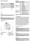
ASI.UM.037.1
Motori asincroni trifase per atmosfere potenzialmente esplosive
SERIE DDK (DDY) 71-315
SERIE DDC (DDX) 71-160
II 2G EEx d (EEx de) II C T3 … T6
II 2G EEx d (EEx de) II B T3 … T6
ITALIANO
Istruzioni e avvertenze sulla sicurezza
Le macchine elettriche a cui si riferiscono le "Istruzioni" sono componenti destinati ad operare in aree industriali (macchine/impianti) e
quindi non possono essere trattati come prodotti per vendita al minuto.
La presente documentazione riporta pertanto le informazioni atte ad essere utilizzate solo da personale qualificato. Esse devono essere
integrate dalle disposizioni legislative e dalle norme tecniche vigenti e non sostituiscono alcuna norma di impianto ed eventuali prescrizioni
aggiuntive, anche non legislative, emanate comunque ai fini della sicurezza.
Macchine in esecuzione speciale o con varianti costruttive possono differire nei dettagli rispetto a quelle descritte.
In caso di difficoltà si prega di contattare l'organizzazione della Marelli Motori specificando:
- tipo della macchina
- codice completo della macchina
- numero di matricola.
E‘ responsabilità dell’impiantista stabilire l’idoneità del motore ad essere utilizzato nel contesto di un determinato
impianto, analizzate le caratteristiche di pericolo esistenti nell’area di installazione e nel rispetto delle vigenti
disposizioni legislative o di quelle emesse comunque ai fini della sicurezza.
Oltre alle avvertenze di sicurezza applicabili ai motori elettrici in genere, i motori per impiego in atmosfere potenzialmente
esplosive richiedono ulteriori prescrizioni volte a non intaccare il modo di protezione del motore e a non introdurre cause di
rischio.
Avvertenze generali sulla sicurezza
PERICOLO
Tutti i diritti riservati
All rights reserved
Le macchine elettriche rotanti sono macchine che presentano parti pericolose in quanto poste sotto tensione
o dotate di movimento durante il funzionamento. Pertanto:
- un uso improprio,
- la rimozione delle protezioni e lo scollegamento dei dispositivi di protezione,
- la carenza di ispezioni e manutenzioni,
possono causare gravi danni a persone o cose.
Il responsabile della sicurezza deve perciò assicurarsi e garantire che la macchina sia movimentata, installata, messa in servizio, gestita,
ispezionata, manutentata e riparata esclusivamente da personale qualificato, che quindi dovrà possedere:
- specifica formazione tecnica ed esperienza, con addestramento che abbia incluso anche istruzioni sui vari modi di protezione e sui
principi generali della classificazione dei luoghi pericolosi,
- conoscenza delle Norme tecniche e delle leggi applicabili,
- conoscenza delle prescrizioni generali di sicurezza, nazionali, locali e dell'impianto,
- capacità di riconoscere ed evitare ogni possibile pericolo.
I lavori sulla macchina elettrica devono avvenire su autorizzazione del responsabile della sicurezza, a macchina ferma, scollegata
elettricamente dalla rete, (compresi gli ausiliari, come ad es. le scaldiglie anticondensa), in assenza di atmosfera esplosiva.
Il motore elettrico è un componente che viene meccanicamente accoppiato ad un'altra macchina (singola o costituente parte di un
impianto); è pertanto responsabilità di chi esegue l'installazione garantire che durante il servizio ci sia un adeguato grado di protezione
contro il pericolo di contatti con parti in movimento che restino scoperte e che sia interdetto un accostamento pericoloso per le persone o le
cose. Misure di protezione aggiuntive devono essere adottate e garantite da chi è responsabile dell'installazione nel caso
necessitino condizioni di protezione più restrittive.
Nel caso che la macchina presenti caratteristiche anomale di funzionamento (assorbimenti maggiori, incrementi delle temperature,
rumorosità, vibrazioni), avvertire prontamente il personale responsabile della manutenzione.
1. Generalità sull’idoneità del motore al luogo di installazione
Nel caso di utilizzo in aree con pericolo di esplosione si deve verificare l’idoneità del motore alla classificazione della zona ed alle
caratteristiche delle sostanze infiammabili presenti sull’impianto.
I requisiti essenziali di sicurezza contro il rischio di esplosione nelle aree classificate sono fissati dalle direttive europee
- 94/9/CE del 23 marzo 1994 per quanto riguarda le apparecchiature,
- 1999/92/CE del 16 dicembre 1999 per quanto riguarda gli impianti.
I criteri per la classificazione delle aree con rischio di esplosione sono dati dalla norma EN 60079-10.
I requisiti tecnici degli impianti elettrici nelle aree classificate sono dati dalla norma EN 60079-14.
In base a queste disposizioni tecniche e legislative la scelta del tipo di motore deve tenere conto dei seguenti fattori:
♦ tipo di impianto: miniere con possibile presenza di grisou (gruppo I), impianti di superficie diversi dalle miniere (gruppo II),
♦ classificazione della zona (per impianti di superficie diversi dalle miniere):
0, 1, 2 (atmosfere potenzialmente esplosive per presenza di gas, vapori o nebbie , per le quali sono idonee apparecchiature
rispettivamente di categoria 1G, 2G, 3G),
♦ caratteristiche delle sostanze infiammabili presenti sotto forma di gas, vapori, nebbie,
- sottogruppo (per il gas): IIA, IIB,IIC
- classe di temperatura: T1, T2, T3, T4, T5,T6 (per i gas) ,
Normalmente non è concesso l’uso dei motori elettrici per la zona 0.
MARELLI MOTORI
1
ASI.UM.037.1
2. Marcatura del motore oggetto della fornitura e controllo della corrispondenza
I motori DD hanno ottenuto la certificazione CE di tipo in accordo alla Direttiva Comunitaria 94/9/ CE - ATEX .
Ciò rende questa serie di motori asincroni idonei ad essere impiegati in aree classificate ove sia richiesta una delle seguenti protezioni:
Gruppo Categoria Modo di protezione Classe di temperatura
serie
II
2G
EEx d II C
T3…T6
DDK
II
2G
EEx de II C
T3…T6
DDY
II
2G
EEx d II B
T3…T6
DDC
II
2G
EEx de II B
T3…T6
DDX
E’ da verificare che tipo di motore (come riportato in targa) e relativa protezione siano compatibili con le specifiche
dell’impianto elettrico a sicurezza in cui la macchina elettrica dovrà essere installata.
Motori del tipo DD di Categoria 2G potranno essere utilizzati anche in aree pericolose per la presenza di gas richiedenti l’impiego di
apparecchiature elettriche appartenenti alla Categoria 3G.
I dati riportati in targa contengono, oltre ai dati funzionali:
- le marcature (specifica e supplementare) relativa al modo di protezione del motore (per impiego in atmosfera potenzialmente
esplosiva),
- i riferimenti agli organismi notificati incaricati della certificazione.
I dati di targa riguardanti la sicurezza sono i seguenti:
Simbolo
Descrizione
Marcatura di conformità alla direttiva 94/9/CE e alle altre direttive europee applicabili
zzzz
Numero dell’organismo notificato che ha effettuato la notifica della qualità del sistema di produzione
(0102 ≡ PTB)
Marcatura specifica ai sensi della direttiva 94/9/CE (ATEX) e delle relative norme tecniche
II 2G
EEx d
EEx de
Motore per impianti di superficie, diversi dalle miniere, con presenza di gas o vapori, di categoria 2,
idoneo per Zona 1 e (con ridondanza) per Zona 2
Motore a prova di esplosione con scatola morsetti a prova di esplosione
Motore a prova di esplosione con scatola morsetti a sicurezza aumentata
IIC
Custodia del gruppo IIC, idonea per sostanze (gas) del gruppo IIC (ed anche dei gruppi IIB e IIA)
II B
Custodia del gruppo IIB, idonea per sostanze (gas) del gruppo IIB (ed anche del gruppo IIA)
T3, T4, T5, T6
ABxx ATEX yyyy
Classe di temperatura del motore (massima temperatura superficiale) idonea alla corrispondente
classe di temperatura della sostanza infiammabile. I motori con una data classe di temperatura sono
idonei anche per tutte le sostanze con classe di temperatura superiore (ad es. motori T4 sono idonei
anche per sostanze con classe di temperatura T3, T2, T1)
AB : nome del laboratorio che ha rilasciato il certificato CE di tipo (PTB)
xx : anno di emissione del certificato CE di tipo (04 ≡ 2004)
yyyy : numero del certificato CE di tipo
Il rispetto delle temperature superficiali massime definite dalla Classe di Temperatura riportata in targa è assicurato qualora la temperatura
ambiente non ecceda i 40°C od il valore indicato in targa.
I motori DD sono utilizzabili in impianti la cui temperatura ambiente minima sia superiore a -20°C ed inferiore a + 40°C (o a valore
superiore se riportato in targa). La temperatura ambiente comunque non deve superare i 60°C.
3. Descrizione
Le macchine oggetto delle presenti istruzioni sono motori asincroni trifasi chiusi antideflagranti con ventilazione esterna, rotore a gabbia e
alimentazione a bassa tensione.
Grado di protezione IP.
Il grado di protezione dei motori è indicato in targa.
Rumorosità.
Le informazioni contenute nelle presenti istruzioni sono riferite ad una ampia gamma di motori e di varianti costruttive.
I valori di
rumorosità, legati alla specifica grandezza, costruzione e velocità, sono indicati nei cataloghi e nella documentazione di prodotto, e sono
contenuti nei valori previsti dalle norme.
Cuscinetti.
I motori montano nell’esecuzione standard cuscinetti a sfere del tipo a doppio schermo (2Z) o, per le taglie più grandi, con ingrassatori.
Il tipo dei cuscinetti è riportato nella targa del motore.
Il posizionamento assiale del rotore è ottenuto mediante bloccaggio del cuscinetto lato D per le grandezze 71÷160 e del cuscinetto lato
N per le grandezze 180÷315.
Il funzionamento di un motore con cuscinetto a rulli in assenza di carichi radiali applicati all’estremità d’albero potrebbe
danneggiare il cuscinetto stesso.
E’ consigliabile la sostituzione dei cuscinetti dopo lo smontaggio del motore e comunque periodicamente, senza attendere il
decadimento funzionale degli stessi.
Accessori.
I motori possono essere provvisti di vari accessori, come resistenze anticondensa, termistori, termorivelatori, unità di ventilazione, ecc. in
relazione a quanto definito in sede di ordine.
2
MARELLI MOTORI
ASI.UM.037.1
4. Trasporto e giacenza a magazzino
Si raccomanda di esaminare il motore accuratamente all'arrivo a destinazione per verificare che non abbia subito danni durante il trasporto;
eventuali danni visibili devono essere denunciati direttamente al trasportatore.
I motori hanno uno o più golfari per il sollevamento e la movimentazione.
I golfari sono adatti al sollevamento del solo motore, non del gruppo nel quale il motore viene incorporato.
Nel depositare la macchina, assicurarsi sempre che siano garantiti appoggi sicuri e stabili.
Di seguito sono riportati i pesi massimi dei motori normali:
Peso max dei motori normali (kg)
Grandezza
71
80
90
100
112
132
160
180
200
kg
25
35
45
60
75
115
215
260
280
225
420
250
515
280
710
315 S
850
315 M
1300
Se il motore non viene posto immediatamente in servizio, dovrà essere immagazzinato in un luogo coperto, pulito, asciutto e privo di
vibrazioni.
Istruzioni aggiuntive per periodi prolungati di immagazzinamento possono essere richieste alla Marelli Motori.
5. Installazione
5.1
Controlli preliminari
L’installatore deve garantire l’effettiva esistenza del tipo di sicurezza che ha consentito la scelta del tipo di
costruzione per la specifica area di installazione, (con il pieno rispetto delle Norme che caratterizzano il tipo di
sicurezza del motore installato), al fine di assicurare l’effettiva efficacia degli apprestamenti di difesa (barriere),
contro il manifestarsi di un evento non voluto propri dei vari modi di protezione.
Prima della installazione, occorre controllare che i dati indicati sulla targa della macchina siano adeguati alle caratteristiche
della rete di alimentazione e del servizio previsto e che l'installazione dei motori sia conforme a quanto previsto dal costruttore.
La classe di temperatura indicata sulla targa del motore deve essere idonea alla classe di temperatura dei gas infiammabili che
potrebbero eventualmente formarsi.
Sono elementi essenziali di barriera:
- l’integrità della custodia (che deve essere priva di incrinature accidentali, forature non autorizzate, coperchi non in sede, fori di ingresso
inutilizzati e non chiusi da tappi certificati);
- le entrate di tubo (che devono essere realizzate con filettatura idonea e munite dei necessari raccordi di bloccaggio);
- le entrate di cavo (che devono essere realizzate con pressacavi di tipo certificato, con perfetto serraggio delle guarnizioni e
dell’eventuale armatura).
Controllare che i motori ad asse verticale con estremità d'albero rivolta verso il basso siano provvisti di tettuccio.
Accertarsi che sui motori che devono funzionare in ambienti particolari siano state predisposte le soluzioni più idonee per garantire un
corretto funzionamento: trattamenti di tropicalizzazione, protezioni contro l'irraggiamento solare diretto, ecc..
Assicurarsi che in funzionamento non sarà superata la velocità massima prevista dal costruttore (prevedere eventualmente dispositivi di
controllo e protezione).
Qualsiasi controllo sul motore deve avvenire previa assicurazione della totale assenza di presenza di atmosfera
esplosiva durante il controllo stesso.
5.2
Prova d'isolamento
Prima della messa in servizio e dopo lunghi periodi di inattività o giacenza a magazzino si dovrà misurare la resistenza d'isolamento tra gli
avvolgimenti e verso massa con apposito strumento in corrente continua (500 V).
Non toccare i morsetti durante e negli istanti successivi alla misurazione in quanto i morsetti sono sotto tensione.
Dopo la misura, gli avvolgimenti vanno scaricati per evitare shock elettrici.
Assicurarsi che non ci sia presenza di eventuale atmosfera esplosiva durante la fase di controllo/misura.
La resistenza d'isolamento, misurata con l'avvolgimento a temperatura di 25°C, non deve essere inferiore a:
- 10 MΩ per avvolgimento nuovo,
- 1 MΩ per avvolgimento di macchina che ha funzionato per diverso tempo.
Valori inferiori sono normalmente indice di presenza di umidità negli avvolgimenti; provvedere in tal caso ad essiccarli fino a che il valore di
resistenza sia superiore al minimo richiesto.
5.3
Equilibratura e montaggio dell'organo di trasmissione
Salvo diversa indicazione, iI rotore è bilanciato dinamicamente con mezza linguetta applicata all'estremità d'albero, secondo la EN 60034-14.
Bilanciare quindi l'organo di trasmissione con mezza linguetta prima del montaggio.
Il montaggio dell'organo di trasmissione deve essere fatto a regola d'arte, senza colpi che danneggerebbero i cuscinetti. Di norma il
montaggio va eseguito a caldo. Si consiglia di scaldare il pezzo alla temperatura di 80÷100 °C (togliendo dal semigiunto le eventuali parti
elastiche deteriorabili). Non avendo la possibilità di scaldare il pezzo si può usare in qualche caso l'attrezzo indicato in fig. 1.
5.4
Condizioni di installazione
Installare il motore in un locale aerato, lontano da fonti di calore. Evitare che la vicinanza di ostacoli impedisca la ventilazione e che l'aria
calda in uscita sia di nuovo aspirata. Ciò può comportare pericolosi aumenti della temperatura superficiale e degli avvolgimenti.
Prevedere la possibilità di effettuare con facilità operazioni di ispezione e manutenzione anche dopo l'installazione.
Il motore dovrà essere sostenuto da un basamento o da una fondazione piana, abbastanza robusta da assorbire le vibrazioni e
sufficientemente rigida da mantenere l'allineamento.
MARELLI MOTORI
3
ASI.UM.037.1
Particolare attenzione deve essere posta nella disposizione delle adeguate protezioni al fine di prevenire il contatto
accidentale con le parti rotanti o con le parti della cassa che possono superare i 50°C.
Nel caso di utilizzo di protezioni termiche, prevedere gli opportuni accorgimenti atti ad evitare i pericoli connessi con la
possibilità di un improvviso riavviamento.
Proteggere elettricamente i motori contro gli effetti dei cortocircuiti, dei sovraccarichi (dispositivo di protezione sulle tre fasi temporizzato, a
tempo inverso, e regolato in funzione della corrente nominale in accordo alla EN 60079-14, con protezione per mancanza di fase) e delle
reinserzioni che possono essere causa di sovratensioni.
Una protezione termica addizionale utilizzante sensori termometrici (termistori
PTC) inseriti negli avvolgimenti del motore, richiede l’uso di un idoneo dispositivo.
Nel caso di accoppiamento con cinghie di trasmissione installare il motore con l'asse parallelo a quello della macchina condotta, per evitare
spinte assiali sui sopporti, e su slitte per poter regolare esattamente la tensione delle cinghie.
Non superare i carichi radiali ed assiali massimi ammessi (possono essere ricavati dai cataloghi o concordati con Marelli Motori).
L’accoppiamento con cinghie deve essere attentamente valutato e comunque deve essere tale da evitare l’accumulo di
cariche elettrostatiche sulle cinghie in movimento, cariche che potrebbero causare scintille (usare cinghie certificate
per ambiente con rischio di esplosione).
In particolare per i motori con forma costruttiva IM V3 , IM V6 , IM V36, IM V19 (sporgenza d’albero verso l’alto) dovrà essere protetto il
motore contro la caduta di materiali all’interno della calotta copriventola.
Per le forme IM V5, IM V1, IM V15, IM V18 (sporgenza d’albero verso il basso) il copriventola dovrà avere il tettuccio di protezione.
5.5
Allineamento
Allineare il motore e la macchina accoppiata accuratamente. Un allineamento impreciso può causare vibrazioni, danneggiamento dei
cuscinetti e rottura dell'estremità d'albero.
L'allineamento si esegue verificando con comparatore o calibro per spessori che la distanza tra i semigiunti sia uguale lungo tutta la
periferia e controllando con comparatore la coassialità delle fasce esterne dei semigiunti (fig. 2).
I controlli vanno eseguiti su quattro punti diametralmente opposti. Gli errori devono essere corretti con spessori infilati tra i piedi e il
basamento.
L'allineamento deve essere sempre ricontrollato dopo il serraggio dei bulloni di fissaggio.
Controllare a mano che il rotore giri facilmente.
5.6
Collegamento elettrico
I lavori sulla macchina elettrica devono avvenire a macchina ferma, scollegata elettricamente dalla rete, (compresi
gli ausiliari, come ad es. le scaldiglie anticondensa).
Per l'esecuzione standard lo schema elettrico dei collegamenti principali del motore è riportato nel § 10.
Impiegare cavi di alimentazione aventi sezione adeguata per sopportare la corrente massima assorbita dal motore, evitando
surriscaldamenti e/o cadute di tensione.
Impedire la trasmissione di sollecitazioni meccaniche ai morsetti del motore.
Verificare che i dadi dei morsetti siano ben serrati.
Assicurarsi che le aperture d’ingresso cavo non utilizzate siano chiuse e che sia garantito il grado di protezione indicato in targa.
I collegamenti equipotenziali con i morsetti di terra posti sulla cassa e nella scatola morsetti, devono essere dimensionati con
una sezione adeguata ed eseguiti secondo le vigenti Norme.
Le superfici di contatto delle connessioni devono essere pulite e protette dalla corrosione.
Nel caso di motori in esecuzione EEx-de (scatola morsetti in esecuzione EEx e) eseguire la connessione ai morsetti
con cura, garantendo le distanze di sicurezza tra parti nude in tensione.
Nell’effettuare i collegamenti devono essere mantenute, tra conduttori a diverso potenziale, le distanze d’isolamento in aria
specificate dalla norma EN 50019 e di seguito riportate:
Tensione nominale U (V)
175 < U ≤ 275
275 < U ≤ 420
420 < U ≤ 550
550 < U ≤ 750
Minima distanza in aria (mm)
5
6
8
10
Allacciamento degli ausiliari (se presenti).
•
Protezioni termiche. Verificare il tipo di protezione installato prima di effettuarne il collegamento. Per i termistori è necessario un
apposito relè di sgancio.
• Resistenze anticondensa. Le resistenze anticondensa (scaldiglie) devono essere alimentate con linea separata rispetto
all’alimentazione del motore. Non devono assolutamente essere alimentate con il motore in funzione.
Controllare che la
tensione corrisponda a quella indicata sull’apposita targa.
• Ventilazione ausiliaria.
Vedere paragrafo specifico (5.7)
I collegamenti di potenza ed ausiliari devono essere effettuati con le coppie di serraggio indicate nel § 6.3.
Entrate di cavo
I collegamenti devono essere realizzati mediante entrate di cavo o condutture in tubo conformi alla norma EN 60079-14.
L’entrata cavi deve essere realizzata in modo da non alterare le proprietà specifiche del modo di protezione.
La scelta del pressacavo deve essere fatta correttamente in rapporto al tipo di impianto e al tipo di cavo. Il pressacavo deve:
- impedire la trasmissione, sui morsetti del motore, di sollecitazioni meccaniche,
- garantire il grado di protezione (IP) e il modo di protezione della scatola morsettiera.
Per le scatole morsetti EEx-d le entrate di cavo devono essere approvate secondo le norme EN 50014 ed EN 50018, con un grado di
protezione minimo IP 55.
Per le scatole morsetti EEx-e le entrate di cavo devono essere approvate secondo le norme EN 50014 ed EN 50019 con un grado di
protezione minimo IP 55.
I pressacavi devono essere certificati e marcati CE per il gruppo II categoria 2G, con modo di protezione compatibile con quello del motore
(ad es. EEx d IIC per i motori con modo di protezione EEx d IIC ed EEx e II per i motori con modo di protezione EEx de IIC).
Collegamento dei dispositivi ausiliari (Termorivelatori, Termistori)
Si raccomanda che il collegamento dei dispositivi accessori integrati nel motore sia realizzato tramite cavi schermati, opportunamente
distanziati dai cavi di alimentazione principale.
4
MARELLI MOTORI
ASI.UM.037.1
5.7
Motori con ventilazione ausiliaria
Collegare separatamente l'alimentazione del motore dell'elettroventilatore da quello del motore principale.
Il motore dell’elettroventilatore deve avere modo di protezione e classe di temperatura congruente con quello del
motore principale.
Predisporre un dispositivo e relativa logica impiantistica che consenta l'avviamento ed il funzionamento del motore
principale solo quando il ventilatore ausiliario è in funzione.
Il controllo deve assicurare che l’esercizio del motore principale dotato di dispositivo di ventilazione ausiliaria potrà avvenire solo
se il dispositivo di protezione termica, utilizzante i dispositivi termorivelatori inseriti nel motore, sia operante.
Il ripristino della alimentazione, dopo un eventuale intervento della protezione termica, non deve essere automatico.
5.8
Motori alimentati da inverter
Dovrà essere verificato che le condizioni di esercizio previste siano compatibili con quanto riportato nella tabella di funzionamento in termini
di coppia e campo di velocità forniti con il motore. Pertanto i motori dovranno essere stati esplicitamente ordinati per alimentazione
da inverter ed essi dovranno riportare il riferimento dell’alimentazione da inverter in targa.
I motori in questo caso devono essere provvisti di protezioni termiche passive (es. termistori, PT100).
Il controllo deve
assicurare che il motore possa funzionare solo quando il dispositivo di protezione termica, utilizzante i dispositivi termorilevatori
del motore, sia operante.
Le apparecchiature che utilizzano le protezioni termiche passive montate nel motore devono essere appropriate ed opportunamente
interfacciate con l’inverter.
Il ripristino dell’alimentazione successivamente all’intervento della protezione termica non dovrà
avvenire in modo automatico.
La scelta del tipo di inverter deve essere effettuata tenendo conto che il motore non deve essere sottoposto a picchi di tensione
superiori ai 1060 V).
Il valore dei picchi di tensione è influenzato anche dalla lunghezza del cavo di alimentazione.
L’inverter deve garantire prestazioni di uscita in termini di forma d’onda e distorsione armonica compatibili con l’alimentazione del motore e
secondo le indicazioni del documento IEC 60034-17.
I motori con tensione nominale superiore a 500 V dovranno essere alimentati tramite opportuni filtri dV/dt o filtri sinusoidale.
I cavi di alimentazione del motore devono essere simmetrici e schermati.
Osservare le istruzioni addizionali fornite dal costruttore dell’inverter.
Sono a carico dell’installatore le soluzioni per rispettare i requisiti di compatibilità elettromagnetica (EMC) dell’impianto.
La realizzazione di una opportuna schermatura faciliterà il rispetto dei requisiti EMC richiesti dall’impianto specifico.
Le tensioni e le correnti nei cuscinetti devono essere evitate nei motori Ex.
Per le grandezze uguali o superiori al 280 i motori per alimentazione da inverter sono forniti con cuscinetto lato N isolato.
Nel caso di sostituzione di tale cuscinetto, si dovrà utilizzare un cuscinetto dello stesso tipo. La definizione completa del tipo di supporto a
rotolamento è riportata nella targa di identificazione del motore.
5.9
Messa in servizio
Prima della messa in servizio controllare che l'installazione, l'allineamento, il collegamento elettrico e la messa a terra siano stati eseguiti
correttamente. Verificare che siano state disposte le protezioni contro i contatti accidentali con parti in tensione o in movimento e che
l'ingresso dell'aria sia libero. Le entrate non utilizzate devono essere tutte chiuse con tappi filettati certificati.
E' consigliabile sostituire il grasso nei sopporti dei motori (o i cuscinetti stessi se del tipo a doppio schermo) che siano stati immagazzinati
per un periodo di circa 3 anni in condizioni favorevoli (asciutto, senza polvere e vibrazioni).
Controllare a mano che il rotore giri
facilmente (senza impedimenti).
Per i motori con metodo di ventilazione IC 416 (dotati di dispositivo servo-ventilatore), occorre predisporre in modo che il motore ausiliario
(che aziona la ventola) sia alimentato da rete a frequenza fissa e sia messo in funzione prima dell’avviamento del motore principale (il cui
funzionamento deve essere quindi interdetto in caso di non funzionamento del motore ausiliario).
Eseguire una prova di funzionamento controllando il senso di rotazione, il rumore meccanico ed i dati funzionali di targa e la temperatura
dei cuscinetti.
I motori devono essere sempre utilizzati entro i limiti d’impiego riportati in targa.
Durante il funzionamento la scatola morsetti deve essere sempre regolarmente chiusa.
6. Manutenzione
Qualsiasi intervento sul motore deve essere effettuato a macchina ferma e scollegata dalla rete di
alimentazione (compresi i circuiti ausiliari, in particolare le resistenze anticondensa).
Non si deve aprire la scatola morsetti di un motore situato in un luogo pericoloso senza che ci si sia accertati
che tutte le alimentazioni siano state preventivamente sezionate e che il motore si sia raffreddato o ci si sia
assicurati dell’assenza di atmosfera esplosiva .
Il disegno riportato § 9, relativo a motori standard, contiene le informazioni adatte ad un operatore qualificato per procedere ad interventi
sul motore.
Le costruzioni speciali possono differire in alcuni dettagli.
Le riparazioni devono essere eseguite presso le Officine della Marelli Motori.
Se non espressamente autorizzata dal costruttore, qualsiasi riparazione eseguita dall’utilizzatore finale fa decadere ogni
responsabilità del costruttore sulla conformità del motore fornito.
Possono essere utilizzati solo ricambi originali.
6.1
Intervalli delle ispezioni e manutenzioni.
Il mantenimento nel tempo delle caratteristiche originali delle costruzioni elettriche deve essere assicurato da un programma di ispezione e
manutenzione, messo a punto e gestito da tecnici qualificati, che tenga conto del servizio e delle reali condizioni ambientali in cui esse
operano.
Le verifiche e la manutenzione dei motori nei luoghi con pericolo di esplosione per la presenza di gas devono essere effettuate secondo i
criteri della norma EN 60079-17.
Un accumulo di sporcizia peggiora la dissipazione del calore del motore e ciò comporta un aumento della temperatura superficiale.
MARELLI MOTORI
5
ASI.UM.037.1
Come regola generale per questo tipo di macchine si raccomandano ispezioni iniziali ravvicinate determinando sperimentalmente la
periodicità delle ispezioni e definendo i programmi di verifica.
E’ responsabilità dell’utente considerare l’eventuale necessità di anticipare un intervento di manutenzione, nel caso si verifichino condizioni
anomale.
In occasione delle ispezioni si verificherà che:
- il motore funzioni regolarmente senza rumori o vibrazioni anomale che denotino deterioramento dei cuscinetti;
- i dati funzionali siano rispettati;
- non siano state apportate modifiche che abbiano alterato la struttura e la funzionalità sia elettrica che meccanica del motore;
- l'ingresso dell'aria sia libero e non ci siano depositi sulla carcassa che possano pregiudicare il raffreddamento;
- i cavi di alimentazione non presentino segni di deterioramento e le connessioni siano fermamente serrate (per evitare anomali
resistenze di contatto e conseguenti surriscaldamenti);
- non siano state escluse/starate le protezioni termiche;
- i conduttori di terra, di protezione o di equipotenzialità siano perfettamente integri (non danneggiati);
- viti e dadi siano fermamente serrati;
- non vi siano perdite di grasso dai supporti;
- gli elementi della trasmissione siano in perfette condizioni .
Le ispezioni sopra citate non richiedono il disaccoppiamento o lo smontaggio della macchina.
Lo smontaggio è necessario quando si effettua la sostituzione o la pulizia dei cuscinetti, in occasione del quale si verificheranno anche:
- l'allineamento;
- la resistenza d'isolamento.
Ogni irregolarità o scostamento rilevato durante i controlli dovrà essere prontamente corretto.
Tutte le operazioni di manutenzione che influenzano la protezione antideflagrante, come per esempio:
- le riparazioni sull’avvolgimento statorico e ai morsetti,
- le riparazioni del sistema di ventilazione,
- lo smontaggio delle macchine,
sono regolati dalla Norma IEC 60079-19.
Tali interventi sono da effettuare nelle officine del fabbricante o, se autorizzato, da una officina specializzata autorizzata (con adeguate
conoscenze tecniche relative anche alle norme specifiche e ai modi di protezione) in modo che siano mantenuti i requisiti essenziali di
sicurezza per la costruzione così come certificata, evitando qualsiasi impatto sul modo di protezione.
Nel caso di riparazioni su parti influenti ai fini della protezione contro il rischio di esplosione, non devono essere modificati i dati costruttivi
del motore (ad esempio: dimensione dei giunti, caratteristiche degli avvolgimenti, ecc.) e le parti riparate devono essere sottoposte a
verifica.
La targa principale non deve mai essere rimossa.
Dovrà essere redatta una dichiarazione scritta attestante gli interventi effettuati.
Se il motore dopo l’intervento di riparazione risulta del tutto conforme alla norma ed al certificato, al motore deve essere applicata una targa
supplementare riportante i seguenti minimi dati:
- simbolo
R ,
- nome o marchio del riparatore,
- tipo di riparazione,
- data della riparazione.
Nel caso di riparazioni che modifichino aspetti rilevanti per la protezione Ex ed il motore dopo la riparazione non risulti più conforme al
certificato, deve essere rimossa la targa originale ed il motore non può più essere considerato idoneo per uso in zone con pericolo di
esplosione.
Per un ulteriore utilizzo in tali zone il motore deve essere nuovamente sottoposto ad un esame eseguito e certificato da un
Organismo di certificazione Notificato.
6.2
Lubrificazione
La maggior parte dei motori standard sono normalmente forniti con cuscinetti ad ingrassaggio permanente di tipo 2Z o, nelle grandezze
maggiori, con ingrassatori.
In targa è indicato il tipo di cuscinetti montati.
Si elencano gli intervalli indicativi per una adeguata lubrificazione in condizioni di funzionamento normali, senza vibrazioni e carichi assiali o
radiali esterni, per i cuscinetti lubrificati permanentemente:
grandezza motore fino al 160:
- 8000-10000 ore per i motori a 2 poli,
- 15000-20000 ore per i motori a 4 poli.
grandezze superiori: i valori sopra citati vanno ridotti con il crescere della taglia di motore/cuscinetto.
Le ore di servizio per i motori ad asse verticale sono da dimezzare.
E’ buona norma comunque prevedere la sostituzione dei cuscinetti dopo 3 anni di esercizio.
Per l’estrazione del cuscinetto utilizzare un estrattore (vedere fig. 3).
Per facilitare il montaggio dei cuscinetti, preriscaldarli (a circa 80°C); evitare di colpirli direttamente con parti metalliche per non
danneggiarli.
In occasione della sostituzione dei cuscinetti è buona norma sostituire anche gli eventuali anelli di tenuta sull’albero, provvedendo ad
ingrassare leggermente la zona di strisciamento del labbro di tenuta.
Ingrassatori
I dati per la rilubrificazione di motori con ingrassatori sono riportati in targa e si riferiscono a funzionamento alla velocità nominale con
condizioni ambientali normali, senza vibrazioni anomale e senza carichi assiali o radiali aggiuntivi.
I motori lubrificati con grasso speciale hanno il tipo di grasso riportato in targa.
Quando si esegue la rilubrificazione dei motori dotati di ingrassatori, togliere il tappo di chiusura dello scarico grasso sullo scudo, pulire
sempre l'ingrassatore e ruotare l'albero in modo che il grasso si distribuisca nel cuscinetto.
Nel periodo di funzionamento immediatamente successivo, la temperatura del cuscinetto aumenta (di 10-15°C) per un periodo transitorio,
per decrescere ai valori normali quando il grasso si sarà uniformemente distribuito e gli eventuali eccessi saranno stati espulsi dalle piste
del cuscinetto.
Una quantità di grasso eccessiva provoca autoriscaldamento dei cuscinetti.
Al termine della rilubrificazione rimettere il tappo di chiusura dello scarico grasso.
6
MARELLI MOTORI
ASI.UM.037.1
Nel caso di impiego del motore con alimentazione da convertitore di frequenza con velocità di rotazione superiore alla velocità nominale ma
compatibile con quanto previsti nel certificato di approvazione, gli intervalli di lubrificazione dovranno essere ridotti.
Gli intervalli di lubrificazione per i motori ad asse verticale sono da dimezzare.
La mescolanza di grassi diversi (addensante, tipo di olio base) ne riduce la qualità e deve essere quindi evitata.
Tipi di grasso consigliati (per applicazioni normali):
Esso – Unirex N3;
SKF – LGHQ 3
Klüber – Kluberplex BEM 41-132;
Shell – Albida EMS2.
6.3
Smontaggio e rimontaggio
Tutte le operazioni vanno eseguite adottando le norme antifortunistiche e rispettando scrupolosamente le avvertenze
sulla sicurezza.
Per lo smontaggio/rimontaggio del motore seguire le indicazioni della IEC 60079-19.
Particolare attenzione dovrà essere posta per non danneggiare gli avvolgimenti.
Marcare i componenti allo smontaggio, se ritenuto necessario, per individuarne la corretta posizione durante il successivo rimontaggio.
Cuscinetti e componenti accoppiati con interferenza devono essere smontati con estrattori (vedi fig. 4). Evitare i colpi forti per non
danneggiare i pezzi.
E' consigliabile sostituire sempre gli anelli di tenuta a labbro (lubrificando leggermente con grasso la relativa sede sull’albero) o V-ring se
presenti.
Nella fase di rimontaggio scaldare i cuscinetti a sfere o l'anello interno dei cuscinetti a rulli ad una temperatura di circa 80°C e montarli sulla
loro sede sull’albero.
Le superfici lavorate di accoppiamento su cassa, scudi, coperchietti, ecc., prima del montaggio devono essere leggermente ricoperte con
pasta adatta non indurente oppure con grasso per proteggerle dalla corrosione. Tali superfici non devono essere sottoposte a lavorazioni
meccaniche e/o verniciate.
Viti, dadi e rosette devono essere montate correttamente (sincerarsi del corretto montaggio e serraggio).
Dovendo sostituire qualche elemento di fissaggio assicurarsi che sia dello stesso tipo e classe di resistenza di quello originale.
In caso di danni ai morsetti passanti che assicurano il collegamento fra le custodie del motore, si dovrà procedere alla loro sostituzione con
parti di ricambio originali.
Nella tabella seguente sono riportate le coppie di serraggio valide per viti e relativi dadi di fissaggio:
Coppie di serraggio in Nm
6.5
Applicazione
M5
M6
M8
M10
M12
M16
M20
Fissaggio di connessioni elettriche
2,1
3,3
6,5
11
16
-
-
Fissaggio di componenti (scudi, coperchietti, ecc.)
5
8
20
40
70
170
340
Parti di ricambio
Nelle eventuali richieste di parti di ricambio, precisare sempre il tipo e il codice del motore indicati in targa.
La designazione del componente sarà quella riportata nel § 8.
Alcuni componenti normalizzati (viti, dadi, cuscinetti, ecc.) sono reperibili anche direttamente da rivenditori specializzati.
Nel caso dei cuscinetti, precisare la designazione completa anche del suffisso (che può identificare caratteristiche particolari) che può
essere rilevata direttamente dal cuscinetto installato. Nel caso dei motori alimentati da inverter di grandezze 280 e 315, il cuscinetto lato N
è isolato: sostituire con cuscinetto isolato di tipo identico.
Eccettuate le parti standard commerciali (per es. i cuscinetti) si devono utilizzare solamente componenti originali.
Gli elementi di fissaggio devono essere dello stesso tipo e classe di resistenza di quelli originali.
MARELLI MOTORI
7
ASI.UM.037.1
Arzignano (VI) - ITALY
Three phase induction motors for potentially explosive atmospheres
SERIE DDK (DDY) 71-315
II 2G EEx d (EEx de) II C T3 … T6
SERIE DDC (DDX) 71-160
II 2G EEx d (EEx de) II B T3 … T6
ENGLISH
Instructions and safety information
The motors to which these “instructions” refers are components designed for use in industrial areas (machines/plants) and therefore
cannot be treated as retail goods.
This documentation consequently contains information that is only suitable for use by qualified personnel. It must be used in
compliance with the regulations, laws and technical Standards in force and cannot, under any circumstances, take the place of plant
standards or additional regulations, including any which are not legally enforceable, which have been issued with the scope of ensuring
safety.
Machines built to customer specifications or with constructional differences may differ in detail from the motors described herein. If you
encounter any difficulties please do not hesitate to contact Marelli Motori, specifying:
- the type of motor
the full motor code number
the serial number
The service/installation engineer shall be responsible for ensuring the motor is suitable for its intended use within a
given plant having analysed the dangers in the installation area in compliance with the technical, safety and any
other relevant regulations in force.
Besides safety information concerning induction motors for standard applications, motors to be used in potentially explosive
atmospheres require/need further instructions to avoid damage and risks the protective casing of the motor.
General safety information
DANGER
Electric rotating motors have dangerous parts: during operation they have live and rotating components.
Therefore:
- improper use,
- the removal of protective covers and the disconnection of protection devices,
- inadequate inspection and maintenance,
can result in severe personal injury or property damage.
The person responsible for safety must therefore ensure that the machine is transported, installed, operated, maintained and repaired
by qualified personnel only, which must have:
- specific training and experience, including instructions on the various types of protection and on the general principles of area
classification,
- knowledge of applicable standards and laws,
- knowledge of the general safety regulations, national and local codes and plant requirements,
- the skill to recognise and avoid possible danger.
All maintenance and inspection operations must be carried out only with the authorisation of the person responsible for
safety, with the machine at a standstill, disconnected from the supply (including the auxiliary circuits such as the anticondensation heaters), and after ensuring no explosive atmosphere is present.
As the electric motor is a component to be coupled to another machine (single or part of an installation), it is the responsibility of the
installing engineer to ensure, during operation, proper protection against the risk of contact with bare rotating parts and to prevent people or
things from approaching the machine is established. Additional protective measures must be taken and assured by the person
responsible for the installation, if stricter protection conditions are required.
If the machine shows deviations from the normal performance (higher power input, increase in temperature, noise and vibrations) promptly
advise the personnel responsible for maintenance.
1. General information on motor suitability for the hazardous area
If the motor is used in potentially explosive atmosphere, it is necessary to verify it is appropriate for the zone classification and the
characteristics of the flammable substances present in the installation.
The Essential Health and Safety Requirements for potentially explosive atmospheres are provided by European Directives:
- 94/9/EC of 23 March 1994 regarding the apparatus,
- 1999/92/EC of 16 December 1999 regarding the protection of workers potentially at risk from explosive atmosphere.
EN 60079-10 standard gives the classification criteria of the hazardous areas.
EN 60079-14 standard gives specific requirements for electrical installations in hazardous areas (other than mines) for explosive gas
atmospheres. According to these technical and legal provisions, the motor choice shall consider the following elements:
♦ type of installation: mines endangered by firedamp (group I), surface installations other than mines (group II),
♦ zone classification (for surface installation different from mines):
0, 1, 2 (potentially explosive atmospheres referred to gases, vapours or mists, for which an apparatus of Category 1G, 2G, 3G is
appropriate);
♦ characteristics of the flammable substances which could be present as gas, vapours, mist,
- gas/vapour subdivision: IIA, IIB,IIC
- temperature class: T1, T2, T3, T4, T5, T6 (for gas),
The use of electrical motors is forbidden for Zones 0.
8
MARELLI MOTORI
ASI.UM.037.1
2. Marking of the motor and checks for suitability to the hazardous environment
DD motors have EC type certification according to European Directive 94/9/EC – ATEX.
Therefore this series of motors is appropriate for use in classified areas where one of the following protections is required:
Group Category
Type of protection
Temperature class
series
II
2G
EEx d II C
T3…T6
DDK
II
2G
EEx de II C
T3…T6
DDY
II
2G
EEx d II B
T3…T6
DDC
II
2G
EEx de II B
T3…T6
DDX
It is to be ensure that motor type (as in the nameplate) and Type of Protection are appropriate to area classification (including
apparatus Group, Category and Temperature Class).
DD motors of Category 2G can be used also in hazardous areas for gases which required electrical apparatus of Category 3G.
In the nameplate there is the motor rating and
- the marking (specific and additional) referred to the type of motor protection (for use in potentially explosive atmosphere).
- the identification of the Notified Bodies that issued the approval certification.
Nameplate data concerning the safety include:
Symbol
Description
CE conformity marking indicating compliance with directive 94/9/EC and other applicable European
Directives.
Zzzz
Identification number of the Notified Body involved in the production control stage
(0102 ≡ PTB)
Specific marking according to 94/9/EC (ATEX) and technical standards
II 2G
EEx d
EEx de
Motor for surface installations, other than mines, where gas/vapours could be present, of Group II and
Category 2 (appropriate for Zone 1 and, with redundancy, for Zone 2).
Motor with flameproof “d” enclosure and terminal box.
Motor with flameproof enclosure and safety increase “e” terminal box.
IIC
Apparatus subgroup IIC, appropriate to IIC gas/vapours subdivision (and also IIB, IIA subdivision)
II B
Apparatus subgroup IIB, appropriate to IIB gas/vapours subdivision (and also IIA subdivision)
T3, T4, T5, T6
ABxx ATEX yyyy
Temperature class of the motor (maximum surface temperature) appropriate to the ignition temperature
of the gas. The motor of a specified temperature class is appropriate also to the higher temp. class
(eg.: T4 motor is appropriate also to gases with T3, T2, T1 temperature class)
AB : code of the Notified Body which has carried out the EC Type examination (PTB)
xx : year of issue (04 ≡ 2004)
yyyy : number of the CE Type examination certificate
With regards to the maximum surface temperature defined by the temperature class on the nameplate, is assured if the ambient
temperature does not exceed 40°C or the ambient temperature marked on the nameplate .
DD motors are for use in ambient temperature range between - 20°C and + 40°C (or higher temperature if it is marked in nameplate). The
ambient temperature in any case cannot exceed + 60°C.
3. Description.
These instructions refer to three-phase squirrel-cage explosion proof motors, fan cooled type for low voltage supply.
Degree of protection (IP)
The degree of protection of motors is shown on the name plate.
Noise level
The information refers to a wide range of motors and type variants. The noise emission data referring to specific size, construction and
speed are mentioned in catalogues and in product documentation, and are within the limits stated by standards.
Bearings
The standard motors are normally equipped with ball bearings of the type double-sealed life-lubricated (2Z) or, for the higher sizes, with
regreasing devices.
The type of motor bearings is specified on the nameplate.
The axial positioning of the rotor is obtained by a locating bearing at D-end for the shaft height 71÷160 and at N-end for the shaft height
180÷315.
The operation of a motor with roller bearings without radial loads to the shaft end could damage the bearing.
It is advisable to replace the bearings after motor dismantling and, in any case , periodically, without waiting for their deterioration.
Accessories
According to the customer’s order, motors can be equipped with accessories, such as anti-condensation heaters, thermistors, fan unit,
etc.
4. Transport and storage
The motor shall be carefully inspected on arrival in order to verify if damage occured during transport; if any are identified, they should
be referred directly to the haulier. The motors have one or more lifting eyes for lifting and handling.
The lifting eyes are designed to support only the weight of the motor, not the weight of the set that incorporates the
motor. When lowering the motor always make sure that it will rest on safe and stable supports.
MARELLI MOTORI
9
ASI.UM.037.1
Motor weight is indicated on the following table:
Size
kg
71
25
80
35
90
45
100
60
Max weight of standard motors (kg)
112
132
160
180
200
75
115
215
260
280
225
420
250
515
280
710
315 S
850
315 M
1300
If the motor is not put into operation immediately, it should be stored in a covered area that is clean, dry and vibration-free place.
Detailed information for long terms storage may be supplied by Marelli Motori if requested.
5. Installation
5.1
Check before installation
The installer must ensure the existence of the type of safety which made the type of construction chosen
admissible for the specific installation area (in full compliance with the standard governing the type of safety
of the motor installed) in order to ensure the effective operation of the defences (barriers), preventing the
occurrence of an undesired event, proper of various types of protection.
Before installing the motor, make sure that name plate data correspond to power supply and operating conditions and that
the installation complies with the manufacturer’s recommendations.
The temperature class shown on the motor’s rating plate must be compatible with the temperature class of any inflammable
gases which might form.
The following are essential barrier elements:
- integrity of the enclosure (which must not have any accidental cracks, unauthorised holes, covers not in place, cable entry holes that
are not used and not blanked off by approved plugs)
- pipe entries (which must be made with a suitable thread and fitted with the necessary tightening unions)
- cable entries (which must be made with certified cable glands with perfect tightening of seals and armour).
Check if vertical construction machines with shaft extension downwards are provided with canopy.
Make sure that the motors to be used in particular ambient conditions are equipped with adequate solutions to operate correctly:
tropicalization treatment, protection against direct sun radiation, special fan cowl for the textile industry, etc..
Make sure that the operating speed will not exceed the maximum speed specified by the manufacturer (control and protection devices
shall be used if necessary).
Before carrying out any testing, ensure the atmosphere is non-explosive while the checks are carried out.
5.2
Insulation testing
Before starting up and after long periods at standstill or storage, the insulation resistance of the windings to earth should be measured using
a suitable DC instrument (500 V).
Never touch the terminals during and immediately after measurement since they may carry dangerous voltages.
After measurement, the windings should be discharged immediately to avoid risks of electric shock.
Ensure no explosive atmosphere is present while the check/measure is in progress.
The insulation resistance, measured with the winding temperature at 25°C, should never be less than:
- 10 MΩ for a new winding
- 1 MΩ for windings of a motor having operated for long periods.
Lower values normally indicate the presence of moisture in the windings. If this is the case dry them, in order to obtain an insulation
resistance value higher than the minimum value required.
5.3
Balancing and assembling of the transmission element
Unless otherwise indicated the rotor is balanced dynamically with a half-key fitted on the shaft extension, in compliance with
EN 60034-14. The transmission element should therefore be balanced with a half-key before fitting.
The transmission element should be fitted with the utmost care, without any blows that might damage the bearings.
Generally speaking, the element should be hot mounted. We recommend heating the component to a temperature of 80-100°C (during
heating, remove from the transmission element any elastic part subject to deterioration).
When it is not possible to heat the part, one can use , the tool illustrated in fig. 1.
5.4
Installation conditions
Install the motor in a ventilated room, far from sources of heat and in a place it so that will prevent obstacles from obstructing
ventilation openings. Warm exhaust air must not be sucked in again. This can increase the temperature of frame surface and windings
with dangerous effects.
Make sure that inspections and maintenance can be carried out easily when the motor is installed.
The motor should be supported by a baseplate or a flat foundation suitable to avoid vibrations and sufficiently rigid to maintain the
alignment.
Special attention should be made to ensure proper guards are provided to prevent accidental contact with rotating
parts and with those parts of the frame whose temperature may arise up to and exceeding 50°C.
If thermal protections are used, take measures to prevent any hazard related to sudden unexpected restarting.
All motors must be protected against the effects of short-circuit, overloads (by a current-dependent, time lag protective device monitoring all
three phases and set in function of the rated current according to EN 60079-14 - §7, with protection for loss of a phase) and against
reconnections which may result from overvoltages. An additional thermal protection using thermometric sensors (thermistors PTC) in the
motor windings needs a suitable tripping device.
For belt drives the motor shall be installed with the axis parallel to the driven machine, to avoid axial loads on the bearings, and on slide
rails to set the right tension of the belts.
10
MARELLI MOTORI
ASI.UM.037.1
Never exceed the maximum permissible axial and radial loads (see catalogues or contact Marelli Motori).
Generally the belt drive use should be carefully considered and in any case has to be made in such a way to
prevent electrostatic charges from accumulating on the moving belt, causing sparks (use belts approved for
hazardous areas).
Motors with IM V3, IM V6, IM V36, IM V19 mounting arrangements (with the shaft extension pointing upwards) must be protected against
objects falling into the fan cowl.
Motors with IM V1, IM V5, IM V15 IM V18 mounting arrangements (with the shaft extension pointing downwards) must have a protective
cover over fan-cowl to protect against falling objects.
5.5
Alignment
Align the motor and the driven machine very carefully, inaccurate alignement may result in vibrations, damages to the bearings
and even shaft extension fracture.
The alignment is done by verifying with a comparator or a thickness caliper that the distance between the half-couplings is the same all
the way around and checking with a comparator or a rule if the external surface of the half-couplings are coaxial (fig. 2).
The check must be performed in four diametrically opposite points.
The errors should be corrected using shims placed between the feet and the base.
Always double-check alignment after tightening fixing bolts.
By hand verify that the rotor turns easily.
5.6
Electrical connection
Works on the electric machine should be carried out with the machine stopped and disconnected from the
power supply (including auxiliary circuits, such as anti-condensation heaters).
The connection diagram for standard motors is illustrated in § 10.
Use power supply cables of a size suitable for the maximum current absorbed by the motor, avoiding overheating and/or voltage drops.
Prevent the transmission of mechanical stresses to the motor terminals. Check that the terminal nuts are firmly tightened.
Make sure that unused cable-entry openings are closed and that the requirements concerning the degree of protection shown
on the name plate are fulfilled.
The potential-equalising connections to the earth terminals on the frame and in the terminal box must be sized with a
suitable cross-section and made in compliance with the Standards in force.
The connections contact surfaces must be clean and protected against corrosion.
The connection to the terminals of motors in version EEx de (terminal box in EEx e execution) has to be carried out
with particular care, assuring safety clearance between conductive live parts.
The electrical connection has to be carried out keeping the minimum clearance between bare conductive parts at different
potentials specified by EN 50019 standard and pointed out in the following table:
Working voltage U (V)
Minimum clearance (mm)
175 < U ≤ 275
5
275 < U ≤ 420
6
420 < U ≤ 550
8
550 < U ≤ 750
10
Connecting up the auxiliary circuits (if present).
•
•
•
Thermal protection devices. Check the type of protective device before connecting it up. Thermistors require a suitable trip
relay.
Anti-condensation heaters. The anti-condensation heaters must be powered by a line separated from the motor line. They must
never under any circumstances be powered when the motor is running. Ensure the voltage is in conformity with the value of
the specific nameplate.
Auxiliary fan unit. See specific section (5.7).
The connection to the terminals have to be carried out with tightening torques from section 6.3.
Cable entries
Connections have to be carried out by cable or conduit entries according to EN 60079-14 standard.
Cable and conduit entries shall be constructed and fixed so that they do not alter the specific characteristics of the type of protection.
The selection of the cable gland must be done in relation to the type of installation and type of cable. The cable gland must:
- prevent pulling or twisting applied to it from being transmitted to the terminals,
- ensure the degree of protection (IP) of the terminal box.
In the EEx–d terminal boxes (flameproof type of protection) the cable entries must be approved according to EN 50014 and EN 50018
standards, with a minimum degree of protection IP 55.
In the EEx-e terminal boxes (safety increased type of protection) the cable entries must be approved according to EN 50014 and
EN 50019 standards, with a minimum degree of protection IP 55.
The cable glands must be CE marked according to Group II Category 2G, with type of protection compatible with one of the motor (e.g.:
EEx d IIC for motors with type of protection EEx d IIC and EEx e II for motors with type of protection EEx de IIC).
Connection of the auxiliary devices (Temperature sensors, Thermistors)
It is advisable that the connection of the auxiliary devices is carried out by shielded cables, sufficient distance from the main supply cables to
ensure safety.
5.7
Motors with auxiliary fan unit
Connect the power supply to the motor of the fan separately from that of the main motor.
The motor of the fan unit shall have the same type of protection and temperature class as the main motor.
Incorporate a device and pertinent control logic which only enables operation of the main motor when the fan unit
is activated/energised.
The electrical control must ensure that the main motor with auxiliary fan kit can only operate when the thermal protective device,
using the motor thermistors, is active.
MARELLI MOTORI
11
ASI.UM.037.1
Do not operate any automatic restarting process of the main motor after tripping of protection devices.
5.8
Motors supplied by frequency converter
The running conditions shall be in accordance with the indications of the operating table supplied with the motors, in terms of torque and
speed range.
Check that the motors have been ordered just for inverter supply , one nameplate must have the indication “inverter
supplied”.
Motors operating with frequency converter must be arranged with passive thermal protection (eg. Thermistors, PT100) fitted in
the windings.
The electrical control must ensure that the motor can only operate when the thermal protective device, using the motor
temperature sensors, is active.
The devices using the passive thermal protection shall be appropriate and the inverter shall be capable of processing this information. Do
not operate any automatic restarting of the main motor after thermal protection tripping.
The inverter has to be selected taking into consideration that the maximum permissible voltage peaks at the motor terminals must not
exceed the value of 1060 V .
The values of the voltage spikes are also linked to the cable length.
The inverter output performances, with reference to the harmonic content, shall be compatible with the supply of motor and according to the
indications of IEC 60034-17.
For motors with a rated voltage higher than 500 V shall be used suitable du/dt filter or sinusoidal filter.
The motor power leads must be symmetric and shielded.
Observe the additional instruction of the converter operating manual.
Whoever is responsible for the installation design has to apply solutions to comply with electromagnetic compatibility (EMC) requirements of
the installation.
The achievement of appropriate screening will facilitate the suitability to EMC requirements of the installation.
Bearing voltages and currents must be avoided in Ex motors.
The motors of size equal or larger than 280 for inverter supply are with insulated N-end bearing.
The replacement of this bearing must be carried out using a bearing of the same type.
The complete definition of the bearing type is on the motor nameplate.
5.9
Commissioning
Before starting up, check if installation, alignment, electrical connection and earthing have been carried out correctly.
Make sure that all protective measures against contact with live or rotating parts have been arranged, and that ventilation openings are not
obstructed. Unused apertures are to be closed with approved plugs.
We recommend to replace the grease in the motor supports that have been stored under favourable conditions (dry, dust and vibrationfree rooms) for a period of 3 years or more.
Verify by hand that the rotor turns freely (without hindrance).
For motors with cooling IC 416, the auxiliary motor (which drives the fan) has to be supplied by net at constant frequency and it has to
operate before the starting of the main motor (whose operation has to be forbidden if the auxiliary motor is not running).
Start up the motor and check the direction of rotation, rotation speed, the name plate rating data and the bearing temperature.
Motors have to operate within the operating limits of the nameplate data.
During the motor operation the terminal box has to be always closed regularly .
6. Maintenance
All maintenance and inspection operations must be carried out with the machine at standstill and
disconnected from the power supply (including auxiliary circuits, especially the anticondensation
heaters).
Do not open the terminal box of a motor installed in a hazardous area before all the supplies are de-energised
and insulated and the motor is cooled or is assured the absence of explosive atmosphere.
The drawing on § 9, referring to standard motors, contains useful information for qualified personnel to understand how is made the
motor. Special construction motors may differ in details from the one illustrated.
Repairs must be carried out in the Marelli Motori workshop.
Any repair by the end user, unless expressly approved by the
manufacturer, releases the manufacturer from his responsibility concerning the conformity of the motor.
Only original spare parts may be used.
6.1
Inspections and maintenance intervals
To ensure electric devices maintain their original characteristics over time, it is essential to implement an inspection and maintenance
programme carried out by qualified engineers which takes into account the importance of the plant ambient conditions (dust etc.)
operating conditions (load, numbers of starts, etc.).
The inspections and maintenance of motors in hazardous areas for explosive gas atmospheres must be carried out according to standard
EN 60079-17 .
The accumulation of dust and dirt reduce the motor’s heat dispersing capacity, causing an increase in the surface temperature.
As general rule for this type of machine, an Initial inspections are recommended followed by periodical checks in order to complete an
inspection schedule.
The user is responsible for evaluating any need to carry out a maintenance operation before the scheduled time due to abnormal
operation.
When performing an inspection check that:
- the motor operates smoothly, without noise or irregular vibrations due to bearing deterioration;
- the operating data complies with rating data;
- no modifications have been made to the structure which alter the electrical and mechanical operation of the motor;
- the air inlet openings are not obstructed and there is not an accumulation of dust and dirt on the frame, which can damage
the cooling;
12
MARELLI MOTORI
ASI.UM.037.1
-
the supply cables show no signs of deterioration and connection are firmly tight (to avoid abnormal contact resistances and
consequent overheating);
- the thermal protections are not disconnected or out of calibration;
- the earth, protection device and potential equalising conductors are in perfect condition (undamaged);
- screws and nuts are firmly tightened;
- there are no grease leakages from supports;
- the transmission elements are in perfect condition.
For the above inspections it is not necessary to dismantle the machine.
Dismantling is only necessary when the bearings are cleaned or replaced. In that occasion the following additional checks are required:
- alignment,
- insulation resistance,
Any deviations or changes found out during inspection must be corrected immediately.
All maintenance activities which impact the flameproof protection, such as:
- rewinding and bushing repairs,
- cooling system repairs,
- dismantling ,
shall comply with IEC 60079-19 standard.
These activities must be undertaken by the manufacturer or, if authorised, by an accredited company (which also has knowledge of relevant
standards and type of protections of the motors) to keep the essential health and safety requirements of the certified apparatus avoiding any
impact on type of protection.
If the repair involves parts concerning the flameproof protection, the construction data of the motor (eg.: dimensions and roughness of
flameproof joints, characteristics of the windings, etc.) must not to be changed and the repaired component must be verified.
The original main nameplate shall be retained.
A written declaration of the repair work shall be compiled.
If the motor, after repair, complies completely to the standards and to the certificate, an additional repair plate shall be added to the motor,
showing the following minimum data:
R
- symbol
- company performing the work,
- kind of repair work,
- date of repair.
If the repair modifies relevant aspects concerning the Ex protection and the motor after the repair does not comply with the certificate, the
original nameplate shall be removed and the motor shall not be suitable for use in hazardous areas anymore.
For a further use in these areas the motor needs an additional examination carried out and certified by a Notified Body.
6.2
Lubrication
Most of the standard motors are normally equipped with ball bearings of the type double-sealed life-lubricated (2Z) or, for the higher
sizes, with regreasing devices.
The type of motor bearings is specified on the nameplate.
The following indicative values of grease life for permanently greased bearings are based on the motor running at normal environment,
without vibrations and external axial or radial loads:
motor size up to 160:
- 8000-10000 hours for 2 pole motors,
- 15000-20000 hours for 4 pole motors.
higher sizes: the above values have to be reduced in function of the size of motor/bearing.
Lubrication intervals for vertical machines are half of the above values.
It is good practice to change the bearings every 3 years in any case.
Use an extractor to remove the bearings (see Fig. 3).
Heat the bearings (to approximately 80°C) to make them easier to fit. Never hit the bearings with a hammer to avoid damaging them.
When changing the bearings it is good practice to also change any seal rings on the shaft, lightly greasing the slip zone of the seal lip.
Regreasing devices
The lubricating data of the motors with regreasing devices are given in the nameplates and they are referred to normal environment, without
vibrations and external axial or radial loads.
Motors lubricated with special grease have grease type in the nameplate.
When lubrication is done on a motor with regreasing devices, remove the plug from the endshield, clean the grease nipple before replacing
the grease, turn the rotor in order to distribute the new grease inside the bearing.
Immediately after regreasing the bearing temperature rises (10-15 °C) for a while, and then drops to normal values after the grease has
been uniformly distributed and the excessive grease displaced from the bearing.
An excessive quantity of grease causes the bearing to self heat.
After regreasing, close the exhaust grease opening with the plug.
Recommended grease types (for standard applications):
Esso – Unirex N3;
SKF – LGHQ 3
Klüber – Kluberplex BEM 41-132;
Shell – Albida EMS2.
Mixing different greases (thickener, basic oil) reduces their quality and is therefore to be avoided. When motor is supplied by a frequency
converter, if the speed range is over the synchronous speed of 50 or 60 Hz but within the certified limits, the lubrication interval must be
shorted.
Lubrication intervals for vertical machines are half of the values for horizontal machines.
6.3
Dismantling and assembling
Any operation whatsoever must be carried out in compliance with laws and regulations for safety and accident
prevention.
Dismantling and reassembling operations must be done according to the indications of standard IEC 60079-19 .
Pay special attention not to damage windings.
If necessary, mark components when dismantling, in order to locate them in their correct position when re-assembling.
MARELLI MOTORI
13
ASI.UM.037.1
Bearings and components assembled with interference fit have to be removed with pullers or extractors, see fig. 6. Avoid sharp blows
that may damage the pieces.
It is advisable to always replace the shaft seal rings (slightly greasing the seat on the shaft) or V-rings if used.
When assembling, heat ball bearing or only the inner ring of roller bearings to a temperature of approx 80°C and slip them on the shaft.
On re-assembly, machined surfaces on frame, endshields, bearing caps, etc., must be cleaned and coated with a suitable nonhardening paste or with grease to prevent corrosion. Those coupling surfaces should not be machined or varnished.
Screws, nuts and washers should be correctly assembled.
If a locking element has to be replaced, make sure that the new one is of the same type and same resistance class as the original.
Damaged bushing terminals (which assure the connections between the enclosures of the motor and the terminal box) must be
replaced only with original spare parts.
Following, table 1, are indicated the tightening torques valid for locking screws and nuts:
Tightening torques in Nm
6.5
Application
M5
M6
M8
M10
M12
M16
M20
Fixing of electrical connections
2,1
3,3
6,5
11
16
-
-
Fixing of components: endshields. bearing cups, etc.
5
8
20
40
70
170
340
Spare parts
In the case of ordering spare parts always state motor type and code as shown on the name plate.
The component description will be the same as the one given on § 8.
Some standardised components (screws, nuts, bearings, etc.) are available from specialised dealers.
When ordering bearings, state the complete description with the suffix (it may indicate special characteristics) that can be taken from the
outer ring of the installed bearing. Motors of sizes 280 and 315 energised by inverter have N-end bearings of the insulated type :
replace it with a bearing of the same type.
Be sure that for spare parts (different than standardised components screws, nuts, bearings) only original components are used.
The fasteners must be of the same type and class of those initially used.
7. Figure
7. Figures
Fig. 1
Fig. 2
Fig. 3
Fig. 4
8. Denominazione dei componenti
Pos. Denominazione
Pos. Denominazione
Pos. Denominazione
100
111
112
200
211
300
301
310
312
313
318
321
400
410
412
413
418
419
510
511
512
520
610
611
612
613
614
620
621
624
Cassa con pacco statore
Piede sinistro
Piede destro
Rotore con albero
Linguetta
Scudo IMB3
Scudo IMB5
Cuscinetto lato D
Coperchietto interno lato D
Coperchietto esterno lato D
Anello di tenuta lato D
Anello elastico di bloccaggio
Scudo lato N
Cuscinetto lato N
Coperchietto interno lato N
Coperchietto esterno lato N
Anello di tenuta lato N
Molla di precarico lato N
Ventola
Copriventola IMB3
Lato D = lato comando
Copriventola IMV1
Linguetta ventola
Scatola morsetti
Coperchio scatola morsetti
Piastra terminali intermedia
Guarnizione scatola/coperchio
Guarnizione scatola/cassa
Morsettiera / morsetto
Passafili EEx d
Morsettiera/morsetto ausiliari
Lato N = lato opposto comando
8. Part name
N°.
Name
N°.
Name
N°.
Name
100
111
112
200
211
300
301
310
312
313
Stator frame with core and windings
Foot-left
Foot-right
Rotor with shaft
Key
Endshield, IM B3
Endshield, IM B5
Bearing, D-side
Inner bearing cap, D-end
Outer bearing cap, D-end
318
321
400
410
412
413
418
419
510
511
Seal ring, D-end
Locking ring
Endshield, N-side
Bearing, N-side
Inner bearing cap, N-end
Outer bearing cap, N-end
Seal ring, N-end
Preload washer, N-end
Fan
Fan cowl, IM B3
512
520
610
611
612
613
614
620
621
624
Fan cowl, IM V1
Fan key
Terminal box
Terminal box cover
Intermediate terminal flange
Gasket - terminal box/ cover
Gasket - terminal box/ frame
Terminal board / Bushing terminal
Flameproof conductor bushing
Auxiliary Terminal board / Bushing terminals
D-end = drive end
14
N-end = non-drive end
MARELLI MOTORI
ASI.UM.037.1
9. Disegni in sezione
9 Cross sections
Costruzione normale.
I motori possono differire nei dettagli rispetto a quelli di seguito illustrati, rimanendo nei limiti di protezione previsti nel Certificato di Approvazione CE
di tipo.
Standard design
Delivered motors may differ in details from those illustrated, remaining within the limits of the type of protection for CE Type certificate.
611- d
EEx d
620
Scatola morsetti - Terminal box
DD . 71
EEx e
620
Scatola morsetti - Terminal box
611- e
613
621
400
510
419
410
418
310
321
318
520
211
512
301
100
511
200
MARELLI MOTORI
111
112
15
ASI.UM.037.1
624 – d
620 - d
DD . 80 ÷ 132
611 - d
EEx d
610 - d
Scatola morsetti - Terminal box
621
EEx e
620 - e
611 - e
Scatola morsetti - Terminal box
613
624 - e
610 - e
400
614
510
621
419
310
410
321
418
318
520
211
(°)
512
511
301
100
200
DD 90, 100, 132
(°) - Grandezze 80 e 112 senza anello interno di bloccaggio / Internal clipring not fitted on sizes 80 and 112
16
MARELLI MOTORI
111
112
ASI.UM.037.1
620
611 - d
610610
EEx d
DD . 160
Scatola morsetti - Terminal
624
621
611 - e
613
610
610 d621
624
EEx e
620
Scatola morsetti - Terminal
400
300
510
313
413
410
310
318
418
211
520
301
512
100
511
200
112
111
EEx e
611 - e
Scatola morsetti
Terminal box
613
610 - e
620
624
DD . 180÷225
300
312
313
400
510
412
310
318
413
410
211
418
520
512
301
100
EEx d
200
200-225
511
Scatola morsetti - Terminal box
611 - d
EEx d 180
611 - d
610 - d
610 - d
MARELLI MOTORI
17
ASI.UM.037.1
620
611- d
624
DD . 250÷315
EEx d
610 - d
Scatola morsetti - Terminal box
612
611- e
610 - e
620
624
EEx e
613
Scatola morsetti - Terminal box
312
400
300
510
313
412
310
413
318
410
211
418
520
512
301
100
511
200
Bearing assembling (standard motors)
Grandezza / Size
71-132
Lato accoppiamento
Drive end
(D)
Lato opposto accoppiamento
Non-drive end
(N)
18
MARELLI MOTORI
160
180-315
ASI.UM.037.1
10.
Schema di collegamento
10.
Leggere attentamente anche il § 5.6.
Connection diagram
Read § 5.6 carefully.
Operare la scelta dello schema in funzione della grandezza del motore e del modo di protezione (EEx d o EEx de),
Select the connection diagram in function of motor size and type of protection (EEx d or EEx de).
SCHEMA DI COLLEGAMENTO / CONNECTION DIAGRAM
DDK - DDC 80 - 90 - 100 - 112 - 132
EEx d
Scatola morsetti - Terminal box : EEx d
MOTORI A SINGOLA VELOCITA’ - SINGLE-SPEED MOTORS
Barretta di collegamento per collegamento a stella
Barretta di collegamento per collegamento a triangolo
Connector bar for star connection
Connector bar for delta connection
Per il cambio di collegamento, girare la barretta (vedi a fondo pagina) /
For connection change, turn the bar (see at the foot of the page)
12- 13: Termistori (PTC) / Thermistors (PTC)
14 - 15: Sensori bimetallici NC (contatto normalmente chiuso) / Bimetal Detectors NC (normally closed contact)
16 - 17: Sensori bimetallici NO (contatto normalmente aperto) / Bimetal Detectors NO (normally open contact)
30 - 31: Scaldiglie / Heaters (230V)
32 – 33: Scaldiglie / Heaters (110 V)
MOTORI A DUE VELOCITA’ - TWO-SPEED MOTORS
DUE AVVOLGIMENTI SEPARATI - TWO SEPARATE WINDINGS
AVVOLGIMENTO UNICO IN COLLEGAMENTO DAHLANDER
SINGLE WINDING WITH DAHLANDER CONNECTION
Collegamento a stella
Star connection
Collegamento a triangolo
Delta connection
Barretta di collegamento - Connection bar
MARELLI MOTORI
19
ASI.UM.037.1
SCHEMA DI COLLEGAMENTO / CONNECTION DIAGRAM
DDK - DDC 71 - 160 - 180 - 200 - 225
EEx d
Scatola morsetti - Terminal box : EEx d
EEx de
DDY - DDX 71 - 80 - 90 - 100 - 112 - 132 - 160 - 180 - 200 - 225
Scatola morsetti - Terminal box : EEx e
12 ⎯ 13
20
MARELLI MOTORI
ASI.UM.037.1
SCHEMA
DICOLLEGAMENTI
COLLEGAMENTO
/ CONNECTION DIAGRAM
SCHEMA
/ CONNECTION DIAGRAM
DDK - DDC DDY
- DDX 250 – 280 - 315
EEx d x
- EEx
DDK - DDC DDY - DDX
250 - 280 - 315
EE
dde- EEx de
Scatola morsetti - Terminal box : EEx d – EEx e
MARELLI MOTORI
21
ASI.UM.037.1
⎯
Senso di rotazione
Direction of rotation
I motori in esecuzione standard possono funzionare
indifferentemente nei due sensi di rotazione.
Se si collega una terna normale destrorsa L1, L2, L3 ai morsetti U,
V, W (1U, 1V, 1W o 2U, 2V, 2W nei motori a due velocità o U1, V1,
W1 nei motori ad una velocità), come indicato negli schemi, il senso
di rotazione del motore risulta orario guardando dal lato comando.
Si può invertire il senso di rotazione invertendo tra loro due terminali
(collegamento L1, L2, L3 a V, U, W oppure a W, V, U).
The standard specification motors can operate in either direction
of rotation. If a normal right-hand L1, L2, L3 triad is connected
to terminals U, V, W (1U, 1V, 1W o 2U, 2V, 2W in two speed
motors or U1, V1, W1 in single speed motors), as shown in the
diagrams, the motor will turn in a clockwise direction, looked at
from drive end. The direction of rotation can be reversed by
swapping the connections to two terminals (connecting L1, L2,
L3 to V, U, W or W, V, U).
⎯⎯⎯⎯⎯⎯⎯⎯⎯⎯⎯⎯⎯⎯⎯⎯⎯⎯⎯⎯⎯⎯⎯⎯⎯⎯⎯⎯⎯⎯⎯⎯⎯⎯⎯⎯⎯⎯⎯⎯⎯⎯⎯⎯⎯⎯
⎯⎯⎯⎯⎯⎯⎯⎯⎯⎯⎯⎯⎯⎯⎯⎯⎯⎯⎯⎯⎯⎯⎯⎯⎯⎯⎯⎯⎯⎯⎯⎯⎯⎯⎯⎯⎯⎯⎯⎯⎯⎯⎯⎯⎯⎯
⎯⎯⎯⎯⎯⎯⎯⎯⎯⎯⎯⎯⎯⎯⎯⎯⎯⎯⎯⎯⎯⎯⎯⎯⎯⎯⎯⎯⎯⎯⎯⎯⎯⎯⎯⎯⎯⎯⎯⎯⎯⎯⎯⎯⎯
⎯⎯⎯⎯⎯⎯⎯⎯⎯⎯⎯⎯⎯⎯⎯⎯⎯⎯⎯⎯⎯⎯⎯⎯⎯⎯⎯⎯⎯⎯⎯⎯⎯⎯⎯⎯⎯⎯⎯⎯⎯⎯⎯⎯⎯⎯
⎯⎯⎯⎯⎯⎯⎯⎯⎯⎯⎯⎯⎯⎯⎯⎯⎯⎯⎯⎯⎯⎯⎯⎯⎯⎯⎯⎯⎯⎯⎯⎯⎯⎯⎯⎯⎯⎯⎯⎯⎯⎯⎯⎯⎯⎯
⎯⎯⎯⎯⎯⎯⎯⎯⎯⎯⎯⎯⎯⎯⎯⎯⎯⎯⎯⎯⎯⎯⎯⎯⎯⎯⎯⎯⎯⎯⎯⎯⎯⎯⎯⎯⎯⎯⎯⎯⎯⎯⎯⎯⎯⎯
⎯⎯⎯⎯⎯⎯⎯⎯⎯⎯⎯⎯⎯⎯⎯⎯⎯⎯⎯⎯⎯⎯⎯⎯⎯⎯⎯⎯⎯⎯⎯⎯⎯⎯⎯⎯⎯⎯⎯⎯⎯⎯⎯⎯⎯⎯
⎯⎯⎯⎯⎯⎯⎯⎯⎯⎯⎯⎯⎯⎯⎯⎯⎯⎯⎯⎯⎯⎯⎯⎯⎯⎯⎯⎯⎯⎯⎯⎯⎯⎯⎯⎯⎯⎯⎯⎯⎯⎯⎯⎯⎯⎯
⎯⎯⎯⎯⎯⎯⎯⎯⎯⎯⎯⎯⎯⎯⎯⎯⎯⎯⎯⎯⎯⎯⎯⎯⎯⎯⎯⎯⎯⎯⎯⎯⎯⎯⎯⎯⎯⎯⎯⎯⎯⎯⎯⎯⎯⎯
⎯⎯⎯⎯⎯⎯⎯⎯⎯⎯⎯⎯⎯⎯⎯⎯⎯⎯⎯⎯⎯⎯⎯⎯⎯⎯⎯⎯⎯⎯⎯⎯⎯⎯⎯⎯⎯⎯⎯⎯⎯⎯⎯⎯⎯⎯
⎯⎯⎯⎯⎯⎯⎯⎯⎯⎯⎯⎯⎯⎯⎯⎯⎯⎯⎯⎯⎯⎯⎯⎯⎯⎯⎯⎯⎯⎯⎯⎯⎯⎯⎯⎯⎯⎯⎯⎯⎯⎯⎯⎯⎯⎯
⎯⎯⎯⎯⎯⎯⎯⎯⎯⎯⎯⎯⎯⎯⎯⎯⎯⎯⎯⎯⎯⎯⎯⎯⎯⎯⎯⎯⎯⎯⎯⎯⎯⎯⎯⎯⎯⎯⎯⎯⎯⎯⎯⎯⎯⎯
⎯⎯⎯⎯⎯⎯⎯⎯⎯⎯⎯⎯⎯⎯⎯⎯⎯⎯⎯⎯⎯⎯⎯⎯⎯⎯⎯⎯⎯⎯⎯⎯⎯⎯⎯⎯⎯⎯⎯⎯⎯⎯⎯⎯⎯⎯
⎯⎯⎯⎯⎯⎯⎯⎯⎯⎯⎯⎯⎯⎯⎯⎯⎯⎯⎯⎯⎯⎯⎯⎯⎯⎯⎯⎯⎯⎯⎯⎯⎯⎯⎯⎯⎯⎯⎯⎯⎯⎯⎯⎯⎯⎯
⎯⎯⎯⎯⎯⎯⎯⎯⎯⎯⎯⎯⎯⎯⎯⎯⎯⎯⎯⎯⎯⎯⎯⎯⎯⎯⎯⎯⎯⎯⎯⎯⎯⎯⎯⎯⎯⎯⎯⎯⎯⎯⎯⎯⎯⎯
⎯⎯⎯⎯⎯⎯⎯⎯⎯⎯⎯⎯⎯⎯⎯⎯⎯⎯⎯⎯⎯⎯⎯⎯⎯⎯⎯⎯⎯⎯⎯⎯⎯⎯⎯⎯⎯⎯⎯⎯⎯⎯⎯⎯⎯⎯
⎯⎯⎯⎯⎯⎯⎯⎯⎯⎯⎯⎯⎯⎯⎯⎯⎯⎯⎯⎯⎯⎯⎯⎯⎯⎯⎯⎯⎯⎯⎯⎯⎯⎯⎯⎯⎯⎯⎯⎯⎯⎯⎯⎯⎯⎯
⎯⎯⎯⎯⎯⎯⎯⎯⎯⎯⎯⎯⎯⎯⎯⎯⎯⎯⎯⎯⎯⎯⎯⎯⎯⎯⎯⎯⎯⎯⎯⎯⎯⎯⎯⎯⎯⎯⎯⎯⎯⎯⎯⎯⎯⎯
⎯⎯⎯⎯⎯⎯⎯⎯⎯⎯⎯⎯⎯⎯⎯⎯⎯⎯⎯⎯⎯⎯⎯⎯⎯⎯⎯⎯⎯⎯⎯⎯⎯⎯⎯⎯⎯⎯⎯⎯⎯⎯⎯⎯⎯⎯
Nota - Note
Se non espressamente autorizzata dal costruttore, qualsiasi riparazione eseguita dall’utilizzatore finale fa decadere ogni responsabilità del costruttore
sulla conformità del motore fornito.
⎯⎯⎯⎯⎯⎯
Any repair by the end user, unless expressly approved by the manufacturer, releases the manufacturer from his responsability to conformity.
Smaltimento - Disposal
Imballo. Tutti i materiali costituenti l’imballo sono ecologici e riciclabili e devono essere trattati secondo le vigenti normative.
Motore dismesso. Il motore dismesso è composto da materiali pregiati riciclabili. Per una corretta gestione contattare l’amministrazione comunale
o l’ente preposto il quale fornirà gli indirizzi dei centri di recupero materiali di rottamazione e le modalità di attuazione del riciclaggio.
⎯⎯⎯⎯⎯⎯
Packaging. All packaging materials are ecological and recyclable and must be treated in accordance with the regulations in force.
Motor to be scrapped. The motor is made of quality recyclabe materials. The municipal administration or the appropriate agency will supply
addresses of the centers for the salvaging of the materials to be scrapped and instructions for the correct procedure.
22
MARELLI MOTORI
ASI.UM.037.1
Con la riserva di eventuali modifiche - Changes reserved
MARELLI MOTORI
23
ASI.UM.037.1
11.04
24
MARELLI MOTORI