Download manuale d`uso e manutenzione maintenance & users manual
Transcript
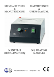
MANUALE D’USO E MANUTENZIONE MAINTENANCE & USERS MANUAL MANTELLI RISCALDANTI MM-MA MM-MA HEATING MANTLES FALC INSTRUMENTS s.r.l. Treviglio (BG) Italy INDICE 1.0 SICUREZZA…………………………………………………………………………………. pag. 1 1.1 GENERALE………………………………………………………………………...…… pag. 1 1.2 QUALIFICA DELL’OPERATORE……………………………………………...……… pag. 1 1.3 RISCHI RESIDUI…………………………………. ……………………………………. pag. 1 2.0 OPERAZIONI PRELIMINARI…………………………………………………………….… pag. 1 2.1 VERIFICA DEI DANNI DOVUTI AL TRASPORTO…………………………….…….pag. 1 2.2 IN CASO DI DANNI……………………………………………………………………. pag. 1 2.3 PULIZIA DELLO STRUMENTO………………………………………………………. pag. 1 3.0 CARATTERISTICHE DELLO STRUMENTO………………………………………………pag. 2 4.0 COMANDI…………………………………………………………………………………… pag. 3 5.0 INSTALLAZIONE E PROCEDURA D’UTILIZZO………………………………………… pag. 4 5.1 CARATTERISTICHE FISICHE………………………………………………………… pag. 4 5.2 MESSA IN FUNZIONE…………………………………………………………………. pag. 4 6.0 USI PREVISTI E NON PREVISTI…………………………………………………………... pag. 5 7.0 MANUTENZIONE……………………………………………………………………………pag. 6 7.1 MANUTENZIONE DELLO STRUMENTO………………………….…………………. pag. 6 7.1.1 MANUTENZIONE ORDINARIA…………………………………………………. pag. 6 7.1.2 MANUTENZIONE PROGRAMMATA…………………………………………… pag. 6 7.2 PULIZIA…………………………………………………………………….……………. pag. 6 7.2.1 ATTREZZI E PRODOTTI PER LA PULIZIA………….………………………… pag. 6 7.3 TRASPORTO…………………………………………………………………………….. pag. 7 7.4 IMMAGAZZINAMENTO……………………………………………………………….. pag. 7 7.4.1 CARATTERISTICHE DI IMMAGAZZINAMENTO……………………………...pag. 7 8.0 SCHEMA ELETTRICO …………………………………………………….………………. pag. 8 9.0 DEMOLIZIONE………..…………………………………………………………..………… pag. 11 9.1 QUALIFICA DELL’OPERATORE…..………………………………………..………… pag. 11 9.2 DISATTIVAZIONE E DEMOLIZIONE………………………...……..………..………. pag. 11 9.3 PROCEDURA DI DISATTIVAZIONE E DEMOLIZIONE……..………………..…….. pag. 11 9.4 RISCHI RESIDUI DOPO LA DEMOLIZIONE…..………..………………………..…... pag. 11 Questo manuale deve essere conservato per tutta la vita tecnica dello strumento in modo da essere facilmente reperibile in caso di necessità. In caso di vendita dello strumento usato dovrà essere venduto completo di questo manuale. Conservare il manuale in luoghi asciutti e facilmente accessibili per una rapida consultazione. Non sporcare il manuale per evitare di creare macchie che impediscano la lettura del testo. 1.0 SICUREZZA 1.1 GENERALE Nella progettazione e nella costruzione di questo apparecchio sono stati adottati i criteri e gli accorgimenti adatti a soddisfare i requisiti essenziali di sicurezza previsti dalla Direttiva Bassa Tensione 2006/95/CE. L’accurata analisi dei rischi svolta ha consentito di eliminare la maggior parte dei rischi connessi alle condizioni di uso dell’apparecchio, sia previste che ragionevolmente prevedibili. La documentazione completa delle misure adottate ai fini della sicurezza è contenuta nel fascicolo tecnico dello strumento, depositato presso il fabbricante. Il fabbricante raccomanda di attenersi scrupolosamente alle istruzioni, procedure e raccomandazioni contenute in questo manuale ed alla vigente legislazione sulla sicurezza nell’ambiente di lavoro, anche per l’utilizzo dei dispositivi di protezione previsti. FALC INSTRUMENTS non si assume responsabilità per eventuali danni a persone, animali o cose derivanti dall’impiego di operatori non qualificati e/o dall’uso improprio dello strumento 1.2 QUALIFICA DELL’OPERATORE Le operazioni di installazione dello strumento devono essere effettuate esclusivamente da personale addestrato, qualificato ed autorizzato, dopo aver studiato e capito il manuale d’uso. 1.3 RISCHI RESIDUI Durante l’utilizzo bisogna evitare che gli arti dell’utilizzatore entrino in contatto con le superfici calde dello strumento come l’elemento riscaldante o come le sostanze riscaldate. Si consiglia di utilizzare guanti o attrezzi adatti alla movimentazione di contenitori caldi. ATTENZIONE Il non utilizzo e/o la manomissione delle protezioni causa rischi per gli utilizzatori dello strumento e per altre persone esposte; per tanto FALC INSTRUMENTS non si assume responsabilità per eventuali danni a persone, animali o cose dovuti a questi comportamenti 2.0 OPERAZIONI PRELIMINARI 2.1 VERIFICA DEI DANNI DOVUTI AL TRASPORTO Verificare lo stato dello strumento tramite un’ispezione visiva dopo aver aperto l’imballo con delicatezza. Eventuali deformazioni delle parti visibili indicano urti subiti dallo strumento durante il trasporto, che potrebbero compromettere il normale funzionamento. In particolare verificare il buono stato delle seguenti parti: - Struttura dello strumento. - Comandi e spie. - Controllare il serraggio delle viti e dei bulloni. 2.2 IN CASO DI DANNI I danni dovuti al trasporto devono essere attribuiti al trasportatore e segnalati immediatamente al fabbricante o al suo responsabile. Inviare una lettera di contestazione al trasportatore. 2.3 PULIZIA DELLO STRUMENTO Togliere la polvere e lo sporco esterni accumulati durante le fasi di trasporto. 1 / 12 3.0 CARATTERISTICHE DELLO STRUMENTO Modello MM 100 MM 250 MM 500 MM 1000 MM 2000 100 250 500 1000 2000 Capacità dei palloni .ml Temperatura °C +350 Precisione °C ±5 Potenza riscaldante W Dimensioni esterne ØxH .mm Peso 130 180 250 450 600 185x145 185x145 205x150 245x175 310x210 1,5 1,5 1,8 2,4 5,0 Kg Codice 625.0500.01 625.0500.02 625.0500.05 625.0500.10 625.0500.20 ATTENZIONE Le temperature massime indicate si riferiscono all’elemento riscaldante. Alimentazione V/Hz 230/50-60 Classe di sicurezza 0 Classe di protezione IP 30 I riscaldatori MM sono frutto di una lunga esperienza. Hanno custodia in acciaio verniciato con polvere epossidica antiacida, i nidi che semirigidi si adattano alla forma del pallone riducendo la possibilità di rottura del pallone, l’isolante termico è costituito da fibra di ceramica. Le temperature sono controllate da un termoregolatore con scala numerata. Tutti i riscaldatori sono dotati di un interruttore ON/OFF con luce verde e di una spia che indica il funzionamento. Modello MA 3 MA 4 MA 6 MA 10 MA 20 MA 50 3000 4000 6000 10000 20000 50000 Capacità dei palloni .ml Temperatura °C +350 Precisione °C ±5 Potenza riscaldante W 600 900 900 1500 2100 3000 Dimensioni esterne ØxH .mm 310 x 290 380 x 310 380 x 310 460 x 330 540 x 510 700 x 650 Peso Kg 6,0 8,0 8,0 11,0 16,5 20,0 Codice 625.0520.03 625.0520.04 625.0520.06 625.0520.10 625.0520.20 625.0520.50 ATTENZIONE Le temperature massime indicate si riferiscono all’elemento riscaldante. Alimentazione V/Hz 230/50-60 Classe di sicurezza 0 Classe di protezione IP 44 I riscaldatori MA per palloni di grosse capacità sono costruiti in maniera da avere una maggior sicurezza rispetto agli MM e vengono dotati di un sistema di recupero liquidi in caso di rottura del pallone. Le strutture esterne e le calotte, rivestite con un tessuto di fibra di vetro, sono completamente in acciaio INOX. Le resistenze vengono fissate al di sotto delle calotte e vengono coibentato con lana di roccia per sfruttare al massimo l’effetto riscaldante e riducendo al minimo la dispersione di calore sulla custodia. La temperatura è controllata da un termoregolatore su scala numerata. Tutti i riscaldatori vengono forniti di un interruttore ON/OFF con luce verde e di una spia che indica il funzionamento. 2 / 12 4.0 COMANDI Elemento riscaldante Rubinetto di scarico Spia luminosa Interruttore generale IG Termoregolatore Elemento riscaldante Spia luminosa Termoregolatore Interruttore generale IG Rubinetto di scarico 3 / 12 Spazio dedicato all’alloggiamento di palloni. Indica il funzionamento della resistenza. Serve per regolare la temperatura. Serve per accendere e spegnere lo strumento. Serve per far fuoriuscire il liquido depositatosi nell’elemento riscaldante in caso di rottura del pallone. ( il rubinetto di scarico è previsto solo per modelli MA ). 5.0 INSTALLAZIONE E PROCEDURA D’UTILIZZO 5.1 CARATTERISTICHE FISICHE Collocare lo strumento in luoghi ritenuti idonei per l’utilizzo (norma D.L. 626/94 - c valutazione rischi). Oltre alle dimensioni di ingombro dello strumento, è necessario rispettare le seguenti condizioni: - In prossimità della zona di collocazione devono essere predisposte le fonti di alimentazione. Lo strumento ha un unico punto di alimentazione elettrica esterna posto sul retro. Verificare che la linea di distribuzione elettrica sia dimensionata in funzione della potenza dell’apparecchio e che sia provvista di impianto a terra (per i dati di tensione controllare l’etichetta posta sul retro dello strumento). __ - Prevedere uno spazio sufficiente ed in piano per il normale utilizzo e manutenzione dello strumento, compreso lo spazio per le eventuali apparecchiature periferiche. _____ _________ In oltre lo strumento deve essere collocato in un locale coperto e protetto dal contatto con gli agenti atmosferici. Per svolgere in sicurezza le fasi di lavorazione e di manutenzione dello strumento è necessaria una buona illuminazione. Una normale illuminazione ambiente permette di lavorare senza rischi dovuti a zone d’ombra. La temperatura ammessa per un normale funzionamento va da un minimo di +5°C ad un massimo di +40°C con umidità relativa massima 80% per temperature sino a +31°C con diminuzione lineare sino al 50 % alla temperatura di +40°C. ATTENZIONE FALC INSTRUMENTS declina ogni responsabilità per inconvenienti, guasti o malfunzionamenti che dovrebbero verificarsi in conseguenza del mancato rispetto delle indicazioni sopra citate. 5.2 MESSA IN FUNZIONE 1) ALLACCIAMENTI ELETTRICI Lo strumento ha un unico punto di alimentazione elettrica esterna, posto sul retro. 2) AVVIAMENTO DI PROVA Prima di procedere all’utilizzo ordinario e continuativo dello strumento verificare il perfetto funzionamento eseguendo almeno un ciclo completo di prova. 3) ACCENSIONE DELLO STRUMENTO - Inserire la presa del cavo di alimentazione nella presa posta sul retro dello strumento. - Inserire la spina del cavo di alimentazione nella presa della rete di alimentazione. - Portare in posizione “1” l’interruttore generale IG. 4) FASE DI SET - Assicurarsi che il rubinetto d scarico sia chiuso (solo per i modelli MA). - Ruotare in senso orario la manopola del termoregolatore e fermarsi in corrispondenza della posizione desiderata. - Ruotando in senso antiorario la temperatura verrà abbassata. POSIZIONE MA 1 2 3 4 5 °C 55 90 160 200 320 POSIZIONE MM 1 2 3 4 5 °C 50 90 125 160 200 POSIZIONE MM 6 7 8 9 °C 240 275 315 350 IMPORTANTE Le temperature riportate si riferiscono alle temperature nell’elemento riscaldante. IMPORTANTE Le temperature riportate sono indicative e non sono da prendere come valore assoluto. 4 / 12 5) PROCEDURA DI ARRESTO DELLO STRUMENTO - Impostare la manopola del termoregolatore su OFF. - La spia luminosa, se accesa, si spegne. - Portare in posizione “0” l’interruttore generale IG. - Togliere dallo strumento il pallone. ATTENZIONE movimentazione di oggetti caldi. - Sezionare lo strumento dalla linea di alimentazione. 6) PROCEDURA DI RECUPERO LIQUIDI Operazione eseguibile solo per i modelli MA in caso di rottura del pallone nell’elemento riscaldante. - Impostare la manopola del termoregolatore su OFF. - La spia luminosa, se accesa, si spegne. - Portare in posizione “0” l’interruttore generale IG. - Togliere i pezzi più grossi di vetro dall’elemento riscaldante. ATTENZIONE movimentazione di oggetti caldi. - Collegare un’estremità di un tubo al rubinetto di scarico e far entrare l’altra estremità in un contenitore in grado di contenere tutto il liquido che prima era presente nel pallone. - Aprire il rubinetto di scarico. - Quando il liquido sarà drenato completamente rimuovere tutti i pezzi di vetro rimasti. ATTENZIONE movimentazione di oggetti caldi. - Chiudere il rubinetto di scarico e scollegare il tubo. ATTENZIONE FALC INSTRUMENTS non si assume alcuna responsabilità per eventuali danni a persone, cose o animali derivanti dal mancato rispetto delle precauzioni prescritte o dal mancato utilizzo dei DPI prescritti. (Vedi capitolo SICUREZZA a pag. 2). 6.0 USI PREVISTI E NON PREVISTI USI PREVISTI Gli apparecchi sono progettati e realizzati per riscaldare e mantenere la temperatura delle soluzioni. Gli apparecchi sono progettati e realizzati per essere utilizzati in laboratorio a fini professionali, industriali e didattici. Gli strumenti sono utilizzabili nel campo della biochimica, nel campo della microbiologia, nel campo dell’ematologia e nel campo della diagnostica. Gli apparecchi sono progettati e realizzati per trattare le sostanze normalmente utilizzate in laboratorio. USI NON PREVISTI Sono usi non previsti tutti gli usi non esplicitamente indicati in USI PREVISTI. Uso degli strumenti in condizione ambientali diverse da quelle indicate. Uso di apparecchi in atmosfere di gas esplosivi. Uso elettromedicale Lavaggio dello strumento con getti d’acqua. Utilizzo di acidi e solventi a contatto diretto con lo strumento. ATTENZIONE FALC INSTRUMENTS non si assume responsabilità per eventuali danni a persone, animali o cose dovuti ad un utilizzo non conforme agli usi sopra citati. 5 / 12 7.0 MANUTENZIONE 7.1 MANUTENZIONE DELLO STRUMENTO Eseguire le operazioni di manutenzione con lo strumento spento e scollegato dalla rete di alimentazione. Assicurarsi che lo strumento sia freddo prima di iniziare qualsiasi operazione. Far eseguire la manutenzione solo da personale specializzato, addestrato e abilitato all’uso, alla preparazione e alla manutenzione solo dopo aver letto attentamente e recepito le raccomandazioni e le istruzioni fornite in questa sezione. 7.1.1 MANUTENZIONE ORDINARIA Rientrano nella manutenzione ordinaria tutte quelle operazioni che possono essere eseguite dall’utilizzatore. Si tratta di operazioni di pulizia, di ispezione periodiche e preventive che consentono l’utilizzo in sicurezza dello strumento. 7.1.2 MANUTENZIONE PROGRAMMATA Rientrano nella manutenzione programmata tutte quelle operazioni che possono essere eseguite solo dal personale autorizzato. Si tratta di ispezioni periodiche preventive e di interventi sullo strumento. Qualora il personale autorizzato ed addestrato non sia in grado di risolvere un determinato problema contattare l’assistenza tecnica. 7.2 PULIZIA ATTENZIONE Eseguire le operazioni di pulizia con l’apparecchio spento e scollegato dalla rete di alimentazione. Al termine di ogni giornata lavorativa e/o ogni sezione di lavoro eseguire un’accurata pulizia dello strumento , in particolare delle seguenti zone: - Superficie superiore dello strumento. - Parte frontale dei comandi. - Superficie circostante allo strumento. - Pavimentazione della zona di lavoro 7.2.1 ATTREZZI E PRODOTTI PER LA PULIZIA Per le operazioni di pulizia è sufficiente disporre di un normale detergente e di acqua. In caso di sporcizia dura da eliminare utilizzare Isopropanolo. ATTENZIONE Evitare l’uso di solventi che danneggiano la vernice e i materiali sintetici. In particolare evitare l’uso di benzina, diluente nitro-perclorato e trielina. 6 / 12 7.3 TRASPORTO Se il trasporto avviene su veicoli stradali con cassone aperto bisogna assicurarsi che lo strumento, il suo corredo e l’imballo siano completamente coperti con una copertura in plastica o equivalente per proteggerli da agenti atmosferici. 7.4 IMMAGAZZINAMENTO Le indicazioni contenute in questa sezione devono essere rispettate durante i periodi di immagazzinamento temporaneo dello strumento che si possono verificare nelle seguenti situazioni. Installazione dello strumento non immediatamente successiva la sua fornitura. Disinstallazione dello strumento e suo immagazzinamento in attesa di ricollocazione. 7.4.1 - 7 / 12 CARATTERISTICHE DI IMMAGAZZINAMENTO Altitudine fino a 2000m. Intervallo di temperatura ammesso: da +5°C a +40°C. Umidità relativa massima 80% per temperature sino a 31°C con diminuzione lineare sino a 50% con temperatura di +40°C. Protezione adeguata da agenti atmosferici. Spazio richiesto sufficiente a effettuare le operazioni di sollevamento e trasporto in maniera sicura e agevole Piano di appoggio orizzontale con portata superiore alla massa dello strumento NON APPOGGIARE NESSUN OGGETTO SOPRA LO STRUMENTO 8.0 SCHEMA ELETTRICO Modello: MM NR A B C COMPONENTI FUSIBILI PRESA FISSAGGIO A RIVETTI INTERRUTTORE BIPOLARE NR D E F COMPONENTI RESISTENZA CORALLATA TERMOREGOLATORE SPIA LUMINOSA 8 / 12 Modello: MA 3 – MA 4 – MA 6 – MA 10 NR A B C 9 / 12 COMPONENTI FUSIBILI PORTA FUSIBILI DA PANNELLO INTERRUTTORE BIPOLARE NR D E F COMPONENTI RESISTENZA CORALLATA TERMOREGOLATORE SPIA LUMINOSA Modello: MA 20 – MA 50 NR A B C COMPONENTI FUSIBILI PORTA FUSIBILI DA PANNELLO INTERRUTTORE BIPOLARE NR D E F COMPONENTI RESISTENZA CORALLATA TERMOREGOLATORE SPIA LUMINOSA 10 / 12 9.0 DEMOLIZIONE 9.1 QUALIFICA DELL’OPERATORE Operatore qualificato è chi ha letto e recepito i contenuti nel capitolo SICUREZZA a pag. 1 e i contenuti del capitolo DEMOLIZIONE a pag. 11. 9.2 DISATTIVAZIONE E DEMOLIZIONE Una volta raggiunta la fine della vita tecnica e operativa dello strumento, lo strumento deve essere disattivato. La messa fuori servizio e in condizioni di non essere più utilizzato per gli scopi per cui a suo tempo era stato progettato e costruito, deve poter comunque rendere possibile il riutilizzo delle materie prime che lo costituiscono. È necessario effettuare una disattivazione e una demolizione in sicurezza dello strumento ATTENZIONE FALC INSTRUMENTS non si assume alcuna responsabilità per danni a persone, cose o animali derivanti dal riutilizzo di singole parti dello strumento per funzioni o situazioni di montaggio differenti da quelle originali. 9.3 PROCEDURA DI DISATTIVAZIONE E DEMOLIZIONE Le operazioni di disattivazione e demolizione dello strumento devono essere affidate solo a personale adeguatamente addestrato ed equipaggiato. Spegnere lo strumento Scollegare le fonti di alimentazione Smontare le seguenti parti: - Parti elettriche. - Parti in plastica. - Piedini di supporto in resina. Nel caso di movimentazione dello strumento fare riferimento ai capitoli INSTALLAZIONE E PROCEDURA D’UTILIZZO pag. 4, TRASPORTO e IMMAGAZZINAMENTO pag. 7. 9.4 RISCHI RESIDUI DOPO LA DEMOLIZIONE Se le indicazioni della sezioni DISATTIVAZIONE E DEMOLIZIONE pag. 11 sono eseguite accuratamente, non esistono rischi residui dopo la disattivazione. ATTENZIONE Lo strumento è realizzato con materiali non biodegradabili. Portare lo strumento in un deposito autorizzato per lo smaltimento. 11 / 12 NOTE: _______________________________________________________________ ________________________________________________________ ________________________________________________________ ________________________________________________________ ________________________________________________________ ________________________________________________________ ________________________________________________________ ________________________________________________________ ________________________________________________________ ________________________________________________________ ________________________________________________________ ________________________________________________________ ________________________________________________________ ________________________________________________________ ________________________________________________________ ________________________________________________________ ________________________________________________________ ________________________________________________________ ________________________________________________________ ________________________________________________________ ________________________________________________________ ________________________________________________________ ________________________________________________________ ________________________________________________________ ________________________________________________________ ________________________________________________________ ________________________________________________________ ________________________________________________________ ________________________________________________________ ________________________________________________________ ________________________________________________________ ________________________________________________________ ________________________________________________________ ________________________________________________________ ________________________________________________________ ________________________________________________________ 12 / 12 INDEX 1.0 SECURITY……………………………..………………………………………….……….. page 1 1.1 GENERAL……………………….….…………………………………….………...…. page 1 1.2 OPERATORS QUALIFICATION….…………………………………….…………… page 1 1.3 RESIDUAL RISKS………………………………. ………………………..…………. page 1 2.0 PRELIMINARY OPERATIONS….……………………………………….…………….… page 1 2.1 CHECK FOR DAMAGE DURING TRANSPORT……….….………………….……. page 1 2.2 IN THE EVENT OF DAMAGE……………………….………………………………. page 1 2.3 CLEANING THE INSTRUMENT…………….……………………………………….page 1 3.0 INSTRUMENTS CHARACTERISTICS……..………………………………………….… page 2 4.0 COMMANDS……………………………………………………………………….……… page 3 5.0 INSTALLATION AND USE PROCEDURES………………...……………....……………page 4 5.1 PHYSICAL CHARACTERISTICS…...…………………………….………………… page 4 5.2 FUNCTIONING…………………………………………………….…………………. page 4 6.0 INTENDED AND UNINTENDED USES…….………………….………………………... page 5 7.0 MAINTENANCE.…………………………………………………………………..……… page 6 7.1 INSTRUMENTS MAINTENANCE………………………………….….…….………. page 6 7.1.1 ORDINARY MAINTENANCE…………………………….……………………. page 6 7.1.2 PROGRAMMED MAINTENANCE….…………….…………………………… page 6 7.2 CLEANING………………………………………….………………….……………… page 6 7.2.1 CLEANING PRODUCTS ………….………………………………….………… page 6 7.3 TRANSPORT………………………………………………………….……………….. page 7 7.4 STORING……………………………………………………….……………………… page 7 7.4.1 STORING CHARACTERISTICS…………………...…….……………………... page 7 8.0 ELECTRICAL WIRING DIAGRAM...…..……………………………..…………………. page 8 9.0 DEMOLITION………..……………………..…………………………………...………… page 11 9.1 OPERATORS QUALIFICATIONS…..………………………………………..………. page 11 9.2 DEACTIVATING AND DEMOLITION…….……….….……………..…………..…. page 11 9.3 DEACTIVATING AND DEMOLITION PROCEDURES…………..……….....……... page 11 9.4 RESIDUAL RISKS AFTER DEMOLITION………..……..…………..…………..…... page 11 This manual should be conserved for the whole technical life of the instrument so that it can be easily consulted in case of need. Conserve the manual in a dry and reachable place for a rapid consultation. Do not stain the manual to avoid creating stains that could prevent the lecture of this text. 1.0 SECURITY 1.1 GENERAL Criteria and notions have been used in the construction of this instrument that guarantee that the instrument complies with the basic safety requirements under Low Voltage Directive 2006/95/EC. The accurate risk analysis carried out by the manufacturer means that the majority of risks connected with the use of the instrument have been eliminated. Full documentation of the adopted safety measures can be found in the technical file held by the manufacturer. The manufacturer recommends that the instructions, procedures and recommendations contained in this manual, together with the security regulations in the working area, be carried out scrupulously even for the use of the intended uses of protections. FALC INSTRUMENTS cannot be held liable for any eventual damage to property, personal injury or injury to pets arising from the use of the instrument by unqualified operators and/or from an improper use of the instrument. 1.2 OPERATOR QUALIFICATIONS This instrument must only be used by trained, qualified and authorised personnel fully familiar with the information contained in this manual. Residual risks during use can be contact of the user’s limbs with the heating element or with the heated substances. We advise to wear gloves or use appropriate tools to move the hot containers. ATTENTION The non use and/or tempering with the protections can cause risks to the instruments user or other persons exposed; therefore FALC INSTRUMENTS cannot be held liable for any eventual damage to property personal injury or injury to pets arising from these procedures 2.0 PRELIMINARY OPERATIONS 2.1 CHECK FOR DAMAGE DURING TRANSPORT Carefully remove the packaging and visually check the instrument for damage. Any dents in the visual parts indicate that the instrument has been knocked during transport, which could compromise it’s normal operation. Check specially for the good conditions of the following parts: Check specially for the good conditions of the following parts: - Instruments case. - Controls and pilot lights. - Check that all accessible screws and nuts are tight. 2.2 IN THE EVENT OF DAMAGE Damage due to transport must be attributed to the carrier and immediately notified to the manufacturer or his representative. 2.3 CLEANING THE INSTRUMENT Remove any dust or external dirt accumulated during transport 1 / 12 3.0 INSTRUMENTS CHARACTERISTICS Model MM 100 MM 250 MM 500 MM 1000 MM 2000 100 250 500 1000 2000 Tank capacity ml Temperature °C +350 Precision °C ±5 Heating Power W External Dimensions ØxH mm Weight Kg Item 625.0500.01 625.0500.02 625.0500.05 625.0500.10 625.0500.20 ATTENTION The maximum indicated temperatures refer to the heating element. Power V/Hz 230/50-60 Security class 0 Protection class IP 30 The MM heaters are the result of a long experience. Steel external casing painted with anti acid epoxy paint. The semi rigid nests which adapt themselves to the flask and like so reduce the breakage of the same, the thermal insulation is made of ceramic fibre. The temperatures are controlled by means of a numbered scale thermo regulator. All heaters are doted with an ON/OFF green light switch and spy light which indicates the functioning of the same. Model MA 3 MA 4 MA 6 MA 10 MA 20 MA 50 3000 4000 6000 10000 20000 50000 Flask capacity ml Temperature °C +350 Precision °C ±5 Heating power W External dimensions ØxH mm Weight Item Kg 600 900 900 1500 2100 3000 310 x 290 380 x 310 380 x 310 460 x 330 540 x 510 700 x 650 6,0 8,0 8,0 11,0 16,5 20,0 625.0520.03 625.0520.04 625.0520.06 625.0520.10 625.0520.20 625.0520.50 ATTENTION The maximum indicated temperatures refer to the heating element. Power V/Hz 230/50-60 Security class 0 Protection class IP 44 The MA heating mantles for large capacities are constructed in order to have a higher security in respect with the MM and are doted with a liquid recuperation system, in case of flask breakage. The external casing and the nest, coated with fibre glass cloth, are completely in STAINLESS STEEL. The resistances are placed underneath the nests and are insulated with rock wool in order to utilize the maximum heating effect and minimally reducing heat dispersion on the external casing. The temperature is controlled by a numbered scale thermo regulator. All heaters are supplied with a green ON/OFF switch and spy light which indicates functioning. 2 / 12 4.0 COMMANDS Heating element Drain tap Luminous spy light General IG switch Thermo regulator Heating Element Luminous Spy Light Indicates the functioning of the resistance Thermo regulator Serves to regulate temperature. General IG Switch Serves to switch on and off the instrument. Drain tap 3 / 12 Space dedicated to the housing of the flasks. Serves to drain the liquid deposited in the heating element in case of flask breakage. ( Drain tap is available only on MA models). 5.0 INSTALLATION AND USE PROCEDURES 5.1 PHYSICAL CHARACTERISTICS Position the instrument in a suitable for use (norm D.L. 626/94-c risk valuation). Other than the overall dimensions, the instrument also requires the following conditions: - In the immediate vicinity of the instrument you must provide power sources. The instrument has only one electrical power source placed on the back of the same. Check that the electrical distribution line is the same as the power required by the instrument and that it is earth grounded (for tension data please control the label placed on the back of the instrument). - Provided a sufficient flat space for the normal use and maintenance of the instrument, and any peripheral equipment._____ _________ The instrument must be placed in a covered area, not exposed to the weather. Good lighting conditions for safe normal operation and maintenance of the instrument. The room where the instrument is used must be lighted sufficiently to allow for operation without risks due to areas in shadow. The accepted temperatures for normal functioning is of a minimum +5°C to a maximum of +40°C with maximum relative humidity of 80% for temperatures up to +31°C with linear reduction 50 % at +40°C. ATTENTION FALC INSTRUMENTS declines any responsibilities for inconveniences, damages or malfunctioning that should arise from the non respect of the above indications. 5.2 FUNCTIONING 1) ELECTRICAL CONNECTIONS The instrument has a single external electrical supply point placed on the back of the same. 2) TRIAL START UP Before regular and continuous use of the instrument, check that it works perfectly by conducting at least one full trial cycle . 3) SWITCHING ON THE INSTRUMENT - Plug in the cable’s plug in the socket placed on the back of the instrument. - Plug in the supply line in at the mains. - Turn to position“1” the general IG switch. 4) SET PHASE - Make sure that the drain tap is closed (only for MA models). - Turn clockwise the thermo-regulator knob and stop when in correspondence with the required position. - Turning the knob anticlockwise will decrease the temperature. MA POSITION 1 2 3 4 5 °C 55 90 160 200 320 MM POSITION 1 2 3 4 5 °C 50 90 125 160 200 MM POSITION 6 7 8 9 °C 240 275 315 350 IMPORTANT The above temperatures refer to the heating element’s temperatures. IMPORTANT The above temperatures are only significant and are not to be taken absolutely as a value. 4 / 12 5) NORMAL STOP PROCEDURE - Turn thermo regulator to position OFF. - The luminous spy light, if on, turns off. - Turn to position “0” the general IG switch. - Remove flask from instrument. ATTENTION movement of hot objects. - Unplug the instrument from the mains. 6) LIQUID RECUPERATION PROCEDURE Operation practicable only for MA models in case of breakage of the heating element in the flask.. - Set to OFF the thermo regulator knob. - The luminous spy light if on, switches off. - Turn to position “0” the general IG switch. - Remove the large pieces of broken glass from the heating element. ATTENTION movement of hot objects. - Connect the one end part of a tube to the drain pipe and place the other end part in a container capable of containing all the liquid that was inside the flask before its breakage. - Open drain tap. - When the liquid is completely drained remove all pieces of glass. ATTENTION movement of hot objects. - Close drain tap and remove the tube. ATTENTION FALC INSTRUMENTS does not assume any responsibilities for damage to property, personal injury or injury to pets arising from the non respect of the prescribed precautions in the DPI. (See chapter “SECURITY” on page 1). 6.0 INTENDED AND UNINTENDED USES INTENDED USES The instruments are projected and manufactured for heating and maintaining the temperature of solutions. The instruments are projected and manufactured for treating substances normally used in laboratories. The instruments are projected and manufactured to be used in laboratories for professional, industrial and teaching purposes. The instruments are to be used in the biochemical, microbiological, haematological and diagnostics field. UNINTENDED USES All uses are unintended unless specifically indicated in INTENDED USES Using the instrument in environment conditions other than those indicated The use of the instrument in explosive atmospheres Electro-medical use Washing the instrument with water jets The use of acids and solvents in direct contact with the instrument ATTENTION FALC INSTRUMENTS does not assume any responsibilities for eventual damage to property, personal injury or injury to pets arising from not using the instrument as specified in the above mentioned uses. 5 / 12 7.0 MAINTENANCE 7.1 INSTRUMENT MAINTENANCE Carry out the maintenance operations with the instrument switched off and unplugged. Make sure that the instrument is cold before starting any type of operation. Maintenance can be carried out in safety by export personnel trained in preparation and maintenance of the instrument and authorised for the use, after having carefully read and fully understood the recommendations and instructions provided in this section. 7.1.1 ORDINARY MAINTENANCE By ordinary maintenance we mean all operations that can be carried out by the user. These consist in cleaning operations, periodic and preventive inspections which allow the use of the instrument in complete safety. 7.1.2 PROGRAMMED MAINTENANCE By programmed maintenance we mean all operations that can be carried out only by authorised personnel. These consist in periodic and preventive inspections of the instrument. Nevertheless if the authorised and trained personnel should not be able to resolve a determined problem, contact the technical assistance. 7.2 CLEANING ATTENTION Carry out cleaning operations with the instrument switched off and unplugged from the mains. At the end of each working day, thoroughly clean the instrument, specially the following parts: - Plate and superior surface of the instrument. - Frontal part of commands. - Surface surrounding the instrument. - The floor around the working area. 7.2.1 CLEANING PRODUCTS For cleaning operations it is sufficient to have a normal detergent and industrial water. In case of stubborn dirt use only isopropyl alcohol. ATTENTION Avoid the use of solvents that could damage the synthetic material or the paint work. In particular avoid the use of benzene, nitroperchlorite and trichloroethylene. 6 / 12 7.3 TRANSPORT If the instrument is transported by opened motor vehicles, the packaged instrument and its fittings must be covered completely by a plastic tarpaulin or equivalent to protect against the weather. 7.4 STORING The indications contained in this section must be observed during temporary storage. Installing the instrument non immediately after being supplied. Deactivating the instrument, its storing whilst waiting for relocation. 7.4.1 - 7 / 12 STORING CHARACTERISTICS Up to 2000m above sea level. Accepted temperatures: from +5°C to +40°C. Maximum relative humidity 80% at temperatures up to 31°C with linear reduction to 50% at +40°C. Adequate weather proofing. Sufficient room to manoeuvre for safe and easy lifting and transport. Horizontal surface capable of bearing more than the weight of the instrument. NEVER PLACE OR REST ANY OBJECT ON THE INSTRUMENT. 8.0 ELECTRICAL WIRING DIAGRAMM Model: MM NR A B C COMPONENTS FUSES RIVET FASTENING SWITCH TWO POLE SWITCH NR D E F COMPONENTS CORAL RESISTANCES THERMO REGULATOR LUMINOUS SPY LIGHT 8 / 12 Models: MA 3 – MA 4 – MA 6 – MA 10 NR A B C 9 / 12 COMPONENTS FUSES PANEL FUSE HOLDER TWO POLE SWITCH NR D E F COMPONENTS CORAL RESISTANCE THERMO REGULATOR LUMINOUS SPY LIGHT Models: MA 20 – MA 50 NR A B C COMPONENTS FUSES PANEL FUSE HOLDER TWO POLE SWITCH NR D E F COMPONENTS CORAL RESISTANCE THERMO REGULATOR LUMINOUS SPY LIGHT 10 / 12 9.0 DEMOLITION 9.1 OPERATORS QUALIFICATIONS A qualified operator who has read and fully understood the contents of chapter “SECURITY” on page 1 and the contents of chapter “DEMOLITION” on page 11. 9.2 DEACTIVATING AND DEMOLITION Once the instrument has reached the end of its technical operation life, the instrument has to be deactivated. Putting the same out of function and putting the instrument in a condition not to be used any more for the scopes which it had initially been projected and constructed, it should, however be possible for the taw materials of the same to be re-used. It is necessary for a deactivating and demolition to be carried out in security of the instrument. ATTENTION FALC INSTRUMENTS cannot be held liable for personal injury or injury to pets arising from the re-use of the single parts of the instrument or installation situations different to the original ones. 9.3 DEACTIVATING AND DEMOLITION PROCEDURES The deactivating and demolition procedures of the instrument have to be carried out only by fully qualified and trained personnel. Switch-off the instrument. Disconnect the power sources. Dismantle the following parts: - Electrical parts. - Plastic Parts. - Resin Support Feet. In case of movement of the instrument refer to chapter INSTALLATION AND OPERATING PROCEDURE page 4, TRANSPORT and STORING page 7. 9.4 RESIDUAL RISKS AFTER DEMOLITION If the indications of section DEACTIVATING AND DEMOLITION page 11, are accurately carried out, there are no residual risks after demolition. ATTENTION The instrument has been constructed with non biodegradable material. Dispose of the instrument in an authorised deposit for the disposal. 11 / 12 NOTE: _______________________________________________________________ ________________________________________________________ ________________________________________________________ ________________________________________________________ ________________________________________________________ ________________________________________________________ ________________________________________________________ ________________________________________________________ ________________________________________________________ ________________________________________________________ ________________________________________________________ ________________________________________________________ ________________________________________________________ ________________________________________________________ ________________________________________________________ ________________________________________________________ ________________________________________________________ ________________________________________________________ ________________________________________________________ ________________________________________________________ ________________________________________________________ ________________________________________________________ ________________________________________________________ ________________________________________________________ ________________________________________________________ ________________________________________________________ ________________________________________________________ ________________________________________________________ ________________________________________________________ ________________________________________________________ ________________________________________________________ ________________________________________________________ ________________________________________________________ ________________________________________________________ ________________________________________________________ ________________________________________________________ 12 / 12 . FALC INSTRUMENTS s.r.l. Via G. Monzio Compagnoni, 2 24047 Treviglio (BG) – ITALY Tel. +39-0363.304660 Fax +39-0363.304395 e-mail: [email protected] web site: www.falcinstruments.it OGGETTO: GARANZIA OBJECTO: GARANTIA Per garanzia si intende la pura e semplice sostituzione, per un periodo limitato a 12 mesi dalla data di consegna, delle parti risultate difettose per manifestati vizi di fabbricazione. Lo strumento dovrà pervenire franco nostro stabilimento (allegando possibilmente una breve descrizione del difetto riscontrato) e se i vizi saranno accettati, verrà riparato e spedito con spese di trasporto a carico nostro. Sono altresì esclusi dalla garanzia i particolari di normale usura (elementi riscaldanti). La garanzia decade qualora l’apparecchio presenti modifiche apportate, manomissioni, o comunque eseguite riparazioni da parte di persone non autorizzate. Por garantia entendemos la pura y simple sostituzion, durante un período limitado de 12 meses a partir da la fecha de entrega, de las partes defectousas a causa de problemas de fabricación. El aparato deberá ser devuelto a nuestra fábrica ex-factory (posiblemente con una explicación incluida). Y el problema será verificado, el aparato será reparado y enviado por nosotros y los gastos del transporte correrán a nuestro cargo. La garantia no será válida si al controlar el aparato comprobamos que el mismo ha sido daňado o ha sido reparado por personas no autorizadas a reparar el mismo. FALC INSTRUMENTS s.r.l. OBJET: GARANTIE On entend par garantie la remplacement pur et simple pendant une période limité à 12 mois à compter de la date de livraison, de pièces s’avérant défectueuses en raison de défauts de fabrication manifestés. L’appareil devra parvenir franco notre usine (accompagné si possible d’un bref descriptif du défaut relevé) et si les défauts sont reconnus comme tels, sera réparé et expédié à nos frais. La garantie exclut par ailleurs toutes les pièces particulières sujettes à une usure normale (pièces chauffantes par exemple). La garantie décline toute responsabilité pour un appareil ayant subi des modifications, des altérations ou encore des réparations effectuées par des personnes non autorisé FALC INSTRUMENTS s.r.l. FALC INSTRUMENTS s.r.l. SUBJECT: GUARANTY For a period of 12 months from the date of delivery to the carrier. With the word “guaranty” we engage ourselves to substitute any and every faulty instrument, product components or part, due to faults or defect of our manufacturing process, not due to transport or misuse, as soon as we are informed and the item sent back to us for verification. The item should be sent back to us at your charge with a report explaining and describing the fault. When the problem has been verified and confirmed, the item shall be substituted or changed repaired and sent back to the customer free of charge. In a case the item has been tampered with, misused, or used not following the instructions, or in case wrong repair trials have been done on it, there shall be no guaranty whatsoever. FALC INSTRUMENTS s.r.l. Dichiarazione di conformità CE Declaration of CE conformity Costruttore/Manufacturer FALC INSTRUMENTS s.r.l. Via G. Monzio Compagnoni, 2 24047 Treviglio (BG) ITALY Dichiara che il seguente apparecchio è conforme alle normative di Sicurezza concernente le DIRETTIVE CE per la COMPATIBILITÀ ELETTROMAGNETICA (2004/108/CE) e la BASSA TENSIONE (2006/95/CE). The following unit complies with the safety requirements outlined by the EC DIRECTIVE concerning the guidelines for ELECTROMAGNETIC COMPATIBILITY (2004/108/EC) and LOW VOLTAGE REGULATIONS (2006/95/EC). Lo strumento è costruito secondo la normativa The units are manufactured in compliance with the regulations CEI EN 61000-6-2 CEI EN 61000-6-4 CEI EN 61010-1 CEI EN 60355-1 CEI EN 61326-1 Il responsabile legale / legal responsable Scotti Francesco 1 / 12 revisione manuale 1.2.1 / manual revision 1.2.1


