Download manuale d`uso e manutenzione maintenance & users manual
Transcript
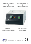
MANUALE D’USO
E
MANUTENZIONE
MAINTENANCE
&
USERS MANUAL
THERMOBLOCK
DIGITALE
DIGITAL
THERMOBLOCK
FALC INSTRUMENTS s.r.l.
Treviglio (BG)
Italy
INDICE
1.0 SICUREZZA…………………………………………………………………………………. pag. 1
1.1 GENERALE………………………………………………………………………...…… pag. 1
1.2 QUALIFICA DELL’OPERATORE……………………………………………...……… pag. 1
1.3 SICUREZZA DELLO STRUMENTO…………………………………………………... pag. 1
1.4 RISCHI RESIDUI…………………………………. ……………………………………. pag. 1
2.0 OPERAZIONI PRELIMINARI…………………………………………………………….… pag. 1
2.1 VERIFICA DEI DANNI DOVUTI AL TRASPORTO…………………………….…….pag. 1
2.2 IN CASO DI DANNI……………………………………………………………………..pag. 1
2.3 PULIZIA DELLO STRUMENTO………………………………………………………. pag. 1
3.0 CARATTERISTICHE DELLO STRUMENTO………………………………………………pag. 2
4.0 COMANDI…………………………………………………………………………………… pag. 2
5.0 INSTALLAZIONE E PROCEDURA D’UTILIZZO………………………………………… pag. 3
5.1 CARATTERISTICHE FISICHE………………………………………………………… pag. 3
5.2 MESSA IN FUNZIONE…………………………………………………………………. pag. 3
6.0 USI PREVISTI E NON PREVISTI…………………………………………………………... pag. 4
7.0 MANUTENZIONE……………………………………………………………………………pag. 5
7.1 MANUTENZIONE DELLO STRUMENTO…………………………………………….. pag. 5
7.1.1 MANUTENZIONE ORDINARIA…………………………………………………. pag. 5
7.1.2 MANUTENZIONE PROGRAMMATA…………………………………………… pag. 5
7.2 PULIZIA………………………………………………………………………………….. pag. 5
7.2.1 ATTREZZI E PRODOTTI PER LA PULIZIA…………..………………………… pag. 5
7.3 TRASPORTO…………………………………………………………………………….. pag. 6
7.4 IMMAGAZZINAMENTO……………………………………………………………….. pag. 6
7.4.1 CARATTERISTICHE DI IMMAGAZZINAMENTO……………………………...pag. 6
8.0 RISOLUZIONE PROBLEMI………………………………………………………………… pag. 6
9.0 SCHEMA ELETTRICO ….………………………………………………….………………. pag. 7
10.0 DEMOLIZIONE………..…………………………………………………………………… pag. 10
10.1 QUALIFICA DELL’OPERATORE…..………………………………………………… pag. 10
10.2 DISATTIVAZIONE E DEMOLIZIONE………………………...……..………………. pag. 10
10.3 PROCEDURA DI DISATTIVAZIONE E DEMOLIZIONE……..…………………….. pag. 10
10.4 RISCHI RESIDUI DOPO LA DEMOLIZIONE…..………..…………………………... pag. 10
Questo manuale deve essere conservato per tutta la vita tecnica dello strumento in modo da essere
facilmente reperibile in caso di necessità. In caso di vendita dello strumento usato dovrà essere venduto
completo di questo manuale.
Conservare il manuale in luoghi asciutti e facilmente accessibili per una rapida consultazione.
Non sporcare il manuale per evitare di creare macchie che impediscano la lettura del testo.
1.0 SICUREZZA
1.1 GENERALE
Nella progettazione e nella costruzione di questo apparecchio sono stati adottati i criteri e gli
accorgimenti adatti a soddisfare i requisiti essenziali di sicurezza previsti dalla Direttiva Bassa Tensione
2006/95/CE.
L’accurata analisi dei rischi svolta ha consentito di eliminare la maggior parte dei rischi connessi alle
condizioni di uso dell’apparecchio, sia previste che ragionevolmente prevedibili.
La documentazione completa delle misure adottate ai fini della sicurezza è contenuta nel fascicolo
tecnico dello strumento, depositato presso il fabbricante.
Il fabbricante raccomanda di attenersi scrupolosamente alle istruzioni, procedure e raccomandazioni
contenute in questo manuale ed alla vigente legislazione sulla sicurezza nell’ambiente di lavoro, anche
per l’utilizzo dei dispositivi di protezione previsti.
FALC INSTRUMENTS non si assume responsabilità per eventuali danni a persone, animali o cose
derivanti dall’impiego di operatori non qualificati e/o dall’uso improprio dello strumento
1.2 QUALIFICA DELL’OPERATORE
Le operazioni di installazione dello strumento devono essere effettuate esclusivamente da personale
addestrato, qualificato ed autorizzato, dopo aver studiato e capito il manuale d’uso.
1.3 SICUREZZA DELLO STRUMENTO
Lo strumento è dotato di una segnalazione visiva del superamento del valore di set point. Quando la
temperatura è superiore di 2°C rispetto al set point si accende la spia di allarme
e si interrompe
immediatamente il riscaldamento.
Questa funzione è anche utilizzata per il raggiungimento della temperatura impostata.
1.4 RISCHI RESIDUI
Durante l’utilizzo bisogna evitare che gli arti dell’utilizzatore entrino in contatto con le superfici calde
dello strumento come la vaschetta di contenimento dei blocchi, i blocchi in alluminio o sostanze
riscaldate. Si consiglia di utilizzare guanti o attrezzi adatti alla movimentazione di contenitori caldi.
ATTENZIONE
Il non utilizzo e/o la manomissione delle protezioni causa rischi per gli utilizzatori dello strumento e per
altre persone esposte; per tanto FALC INSTRUMENTS non si assume responsabilità per eventuali danni
a persone, animali o cose dovuti a questi comportamenti
2.0 OPERAZIONI PRELIMINARI
2.1 VERIFICA DEI DANNI DOVUTI AL TRASPORTO
Verificare lo stato dello strumento tramite un’ispezione visiva dopo aver aperto l’imballo con
delicatezza. Eventuali deformazioni delle parti visibili indicano urti subiti dallo strumento durante il
trasporto, che potrebbero compromettere il normale funzionamento.
In particolare verificare il buono stato delle seguenti parti:
- Struttura dello strumento.
- Comandi e spie.
- Controllare il serraggio delle viti e dei bulloni.
2.2 IN CASO DI DANNI
I danni dovuti al trasporto devono essere attribuiti al trasportatore e segnalati immediatamente al
fabbricante o al suo responsabile. Inviare una lettera di contestazione al trasportatore.
2.3 PULIZIA DELLO STRUMENTO
Togliere la polvere e lo sporco esterni accumulati durante le fasi di trasporto.
1 / 10
3.0 CARATTERISTICHE DELLO STRUMENTO
Modello
TD 150 P1
TD 150 P2
TD 150 P3
n°
1
2
3
Temperatura massima
°C
+ 150
+ 150
+ 150
Precisione sul blocco
37°C
± 0,5
± 0,5
± 0,5
W
90
180
270
mm
220 x 185 x 95
220 x 225 x 95
220 x 325 x 95
Kg
2,2
2,8
3,6
621.0422.01
621.0422.02
621.0422.03
Posto per blocchi
.
Potenza riscaldante
Dimensioni esterne LxPxH
Peso
.
Codice
ATTENZIONE Le temperature massime indicate si riferiscono all’interno del portablocchi.
ATTENZIONE La taratura dello strumento viene effettuata a 37°C
Alimentazione V/Hz
230/50-60
Classe di sicurezza
0
Classe di protezione
IP 40
Custodia esterna in acciaio verniciata a forno con polvere epossidica antiacida, la vaschetta di
contenimento dei blocchi è realizzata in alluminio in modo da assicurare una distribuzione uniforme del
calore.
Il controllo e l’impostazione dei valori avviene tramite un termoregolatore digitale con microprocessore
ad azione PID e una sonda PT100 per una migliore precisione della temperatura. Il riscaldamento del
thermoblock è costituito da resistenze poste al di sotto della vaschetta, tutti gli strumenti vengono dotati
di un interruttore ON/OFF con luce verde.
4.0 COMANDI
Serve per accendere e spegnere lo
strumento.
Visualizza la temperatura corrente o la
Display
temperature impostata.
IG
Interruttore generale IG
Display
Enter
Enter
Up
Per ulteriori informazioni vedere capitolo
5.2 MESSA IN FUNZIONE a pag. 3.
Down
Conferma le modifiche effettuate.
Up
Incrementa la temperatura impostata.
Down
Decrementa la temperatura impostata.
Si accende quando le resistenze sono
in funzione o durante la fase di set.
Si accende quando la temperatura è
inferire all’impostazione.
Si accende quando la temperatura è
uguale all’impostazione.
Si accende quando la temperatura è
superiore all’impostazione.
Si accende durante la fase di set o se il
set point è superato di 2°C.
2 / 10
5.0 INSTALLAZIONE E PROCEDURA D’UTILIZZO
5.1 CARATTERISTICHE FISICHE
Collocare lo strumento in luoghi ritenuti idonei per l’utilizzo (norma D.L.626/94 - c valutazione rischi).
Oltre alle dimensioni di ingombro dello strumento, è necessario rispettare le seguenti condizioni:
- In prossimità della zona di collocazione devono essere predisposte le fonti di alimentazione. Lo
strumento ha un unico punto di alimentazione elettrica esterna posto sul retro. Verificare che la linea di
distribuzione elettrica sia dimensionata in funzione della potenza dell’apparecchio e che sia provvista
di impianto a terra (per i dati di tensione controllare l’etichetta posta sul retro dello strumento). __
- Prevedere uno spazio sufficiente ed in piano per il normale utilizzo e manutenzione dello strumento,
compreso lo spazio per le eventuali apparecchiature periferiche. _____ _________
In oltre lo strumento deve essere collocato in un locale coperto e protetto dal contatto con gli agenti
atmosferici. Per svolgere in sicurezza le fasi di lavorazione e di manutenzione dello strumento è
necessaria una buona illuminazione. Una normale illuminazione ambiente permette di lavorare senza
rischi dovuti a zone d’ombra. La temperatura ammessa per un normale funzionamento va da un minimo
di +5°C ad un massimo di +40°C con umidità relativa massima 80% per temperature sino a +31°C con
diminuzione lineare sino al 50 % alla temperatura di +40°C.
ATTENZIONE
FALC INSTRUMENTS declina ogni responsabilità per inconvenienti, guasti o malfunzionamenti che
dovrebbero verificarsi in conseguenza del mancato rispetto delle indicazioni sopra citate.
5.2 MESSA IN FUNZIONE
1) ALLACCIAMENTI ELETTRICI
Lo strumento ha un unico punto di alimentazione elettrica esterna, posto sul retro.
2) AVVIAMENTO DI PROVA
Prima di procedere all’utilizzo ordinario e continuativo dello strumento verificare il perfetto
funzionamento eseguendo almeno un ciclo completo di prova.
3) ACCENSIONE DELLO STRUMENTO
- Inserire la presa del cavo di alimentazione nella presa posta sul retro dello strumento.
- Inserire la spina del cavo di alimentazione nella presa della rete di alimentazione.
- Portare in posizione “1” l’interruttore generale IG. Lo strumento inizierà a scaldare.
4) FASE DI SET
- Premendo il tasto Up o Down compare il valore del SET POINT.
- Utilizzare il tasto Up o il tasto Down per impostare il valore di temperatura desiderato.
- Per memorizzare il nuovo valore si deve infine premere il tasto Enter.
Se per quattro secondi non si preme alcun tasto il display torna ad indicare la temperatura corrente.
In posizione centrale, sotto al display, è presente un indicatore di scostamento a tre LED: verde al centro
e rossi i due laterali. Ci sono cinque possibili segnalazioni:
3 / 10
→
La temperatura è inferiore di 1,5°C dal SET POINT.
→
La temperatura è entro -1°C dal SET POINT.
→
La temperatura è ± 0,5°C dal SET POINT.
→
La temperatura è entro +1°C dal SET POINT.
→
La temperatura è maggiore di 1,5°C dal SET POINT.
5) PROCEDURA DI ARRESTO DELLO STRUMENTO
- Portare in posizione “0” l’interruttore generale IG.
- Togliere dallo strumento i contenitori e i blocchi.
ATTENZIONE movimentazione di oggetti caldi.
- Sezionare lo strumento dalla linea di alimentazione.
ATTENZIONE
FALC INSTRUMENTS non si assume alcuna responsabilità per eventuali danni a persone, cose o
animali derivanti dal mancato rispetto delle precauzioni prescritte o dal mancato utilizzo dei DPI
prescritti. (Vedi capitolo SICUREZZA a pag. 1).
6.0 USI PREVISTI E NON PREVISTI
☺ USI PREVISTI
Gli apparecchi sono progettati e realizzati per riscaldare a secco e mantenere la temperatura delle
soluzioni.
Gli apparecchi sono progettati e realizzati per trattare le sostanze normalmente utilizzate in
laboratorio
Gli apparecchi sono progettati e realizzati per essere utilizzati in laboratorio a fini professionali,
industriali e didattici.
Gli strumenti sono utilizzabili nel campo della biochimica, nel campo della microbiologia, nel
campo dell’ematologia e nel campo della diagnostica.
USI NON PREVISTI
Sono usi non previsti tutti gli usi non esplicitamente indicati in USI PREVISTI
Uso degli strumenti in condizione ambientali diverse da quelle indicate
Uso di apparecchi in atmosfere di gas esplosivi
Uso elettromedicale
Lavaggio dello strumento con getti d’acqua
Utilizzo di acidi e solventi a contatto diretto con lo strumento
ATTENZIONE
FALC INSTRUMENTS non si assume responsabilità per eventuali danni a persone, animali o cose
dovuti ad un utilizzo non conforme agli usi sopra citati.
4 / 10
7.0 MANUTENZIONE
7.1 MANUTENZIONE DELLO STRUMENTO
Eseguire le operazioni di manutenzione con lo strumento spento e scollegato dalla rete di alimentazione.
Assicurarsi che lo strumento sia freddo prima di iniziare qualsiasi operazione.
Far eseguire la manutenzione solo da personale specializzato, addestrato e abilitato all’uso, alla
preparazione e alla manutenzione solo dopo aver letto attentamente e recepito le raccomandazioni e le
istruzioni fornite in questa sezione.
7.1.1 MANUTENZIONE ORDINARIA
Rientrano nella manutenzione ordinaria tutte quelle operazioni che possono essere eseguite
dall’utilizzatore. Si tratta di operazioni di pulizia, di ispezione periodiche e preventive che
consentono l’utilizzo in sicurezza dello strumento.
7.1.2 MANUTENZIONE PROGRAMMATA
Rientrano nella manutenzione programmata tutte quelle operazioni che possono essere eseguite
solo dal personale autorizzato. Si tratta di ispezioni periodiche preventive e di interventi sullo
strumento.
Qualora il personale autorizzato ed addestrato non sia in grado di risolvere un determinato problema
contattare l’assistenza tecnica.
7.2 PULIZIA
ATTENZIONE
Eseguire le operazioni di pulizia con l’apparecchio spento e scollegato dalla rete di alimentazione.
Al termine di ogni giornata lavorativa e/o ogni sezione di lavoro eseguire un’accurata pulizia dello
strumento , in particolare delle seguenti zone:
- Piastra e superficie superiore dello strumento.
- Parte frontale dei comandi.
- Superficie circostante allo strumento.
- Pavimentazione della zona di lavoro
7.2.1 ATTREZZI E PRODOTTI PER LA PUILIZIA
Per le operazioni di pulizia è sufficiente disporre di un normale detergente e di acqua. In caso di
sporcizia dura da eliminare utilizzare Isopropanolo.
ATTENZIONE
Evitare l’uso di solventi che danneggiano la vernice e i materiali sintetici. In particolare evitare l’uso di
benzina, diluente nitro-perclorato e trielina.
5 / 10
7.3 TRASPORTO
Se il trasporto avviene su veicoli stradali con cassone aperto bisogna assicurarsi che lo strumento, il suo
corredo e l’imballo siano completamente coperti con una copertura in plastica o equivalente per
proteggerli da agenti atmosferici.
7.4 IMMAGAZZINAMENTO
Le indicazioni contenute in questa sezione devono essere rispettate durante i periodi di
immagazzinamento temporaneo dello strumento che si possono verificare nelle seguenti situazioni.
Installazione dello strumento non immediatamente successiva la sua fornitura.
Disinstallazione dello strumento e suo immagazzinamento in attesa di ricollocazione.
7.4.1
-
CARATTERISTICHE DI IMMAGAZZINAMENTO
Altitudine fino a 2000m.
Intervallo di temperatura ammesso: da +5°C a +40°C.
Umidità relativa massima 80% per temperature sino a 31°C con diminuzione lineare sino a
50% con temperatura di +40°C.
Protezione adeguata da agenti atmosferici.
Spazio richiesto sufficiente a effettuare le operazioni di sollevamento e trasporto in maniera
sicura e agevole
Piano di appoggio orizzontale con portata superiore alla massa dello strumento
NON APPOGGIARE NESSUN OGGETTO SOPRA LO STRUMENTO
8.0 RISOLUZIONE PROBLEMI
Guasto riscontrato
Cause
Lo strumento non si accende
1) Lo strumento non è ben collegato alla linea di alimentazione.
2) I fusibili posti sul retro nella presa sono bruciati.
3) Ci sono problemi nella linea di alimentazione.
Lo strumento non scalda
1) Lo strumento è spento.
2) Il valore del set point è inferiore alla temperatura ambiente.
3) * Il termoregolatore digitale dello strumento non funziona
correttamente ( contattare l’assistenza tecnica ).
4) * Le resistenze sono bruciate ( contattare l’assistenza tecnica ).
* I guasti descritti sono riconducibili ad un utilizzo dello strumento non conforme alle procedure del
manuale, alla vita tecnica dei vari componenti e all’usura del tempo.
Qualora il personale autorizzato ed addestrato non sia in grado di risolvere un determinato problema
contattare l’assistenza tecnica.
6 / 10
9.0 SCHEMA ELETTRICO
MODELLO: TD 150 P1
NR
A
B
C
7 / 10
COMPONENTI
FUSIBILI
PRESA AD INNESTO
INTERRUTTORE BIPOLARE
NR COMPONENTI
D TERMOREG. TM FALC
E SONDA PT100
F
RESISTENZA IN MICA
MODELLO: TD 150 P2
NR
A
B
C
COMPONENTI
FUSIBILI
PRESA AD INNESTO
INTERRUTTORE BIPOLARE
NR COMPONENTI
D TERMOREG. TM FALC
E SONDA PT100
F
RESISTENZA IN MICA
8 / 10
MODELLO: TD 150 3P
NR
A
B
C
9 / 10
COMPONENTI
FUSIBILI
PRESA AD INNESTO
INTERRUTTORE BIPOLARE
NR COMPONENTI
D TERMOREG. TM FALC
E SONDA PT100
F
RESISTENZA IN MICA
10.0 DEMOLIZIONE
10.1 QUALIFICA DELL’OPERATORE
Operatore qualificato è chi ha letto e recepito i contenuti nel capitolo SICUREZZA a pag. 1 e i contenuti
del capitolo DEMOLIZIONE a pag. 10.
10.2 DISATTIVAZIONE E DEMOLIZIONE
Una volta raggiunta la fine della vita tecnica e operativa dello strumento, lo strumento deve essere
disattivato. La messa fuori servizio e in condizioni di non essere più utilizzato per gli scopi per cui a suo
tempo era stato progettato e costruito, deve poter comunque rendere possibile il riutilizzo delle materie
prime che lo costituiscono.
È necessario effettuare una disattivazione e una demolizione in sicurezza dello strumento
ATTENZIONE
FALC INSTRUMENTS non si assume alcuna responsabilità per danni a persone, cose o animali derivanti
dal riutilizzo di singole parti dello strumento per funzioni o situazioni di montaggio differenti da quelle
originali.
10.3 PROCEDURA DI DISATTIVAZIONE E DEMOLIZIONE
Le operazioni di disattivazione e demolizione dello strumento devono essere affidate solo a personale
adeguatamente addestrato ed equipaggiato.
Spegnere lo strumento
Scollegare le fonti di alimentazione
Smontare le seguenti parti:
- Parti elettriche.
- Parti in plastica.
- Piedini di supporto in resina.
Nel caso di movimentazione dello strumento fare riferimento ai capitoli INSTALLAZIONE E
PROCEDURA D’UTILIZZO pag. 3, TRASPORTO e IMMAGAZZINAMENTO pag. 6.
10.4 RISCHI RESIDUI DOPO LA DEMOLIZIONE
Se le indicazioni della sezioni DISATTIVAZIONE E DEMOLIZIONE pag. 10 sono eseguite
accuratamente, non esistono rischi residui dopo la disattivazione.
ATTENZIONE
Lo strumento è realizzato con materiali non biodegradabili. Portare lo strumento in un deposito
autorizzato per lo smaltimento.
10 / 10
INDEX
1.0 SECURITY…………………………………………………………………………………. page 1
1.1 GENERAL…..………………………………………………………………….…...…. page 1
1.2 OPERATOR QUALIFICATIONS…......……………………………………………… page 1
1.3 INSTRUMENTS SECURITY…………………………………………….…………… page 1
1.4 RESIDUAL RISKS……………………………………………….…………………… page 1
2.0 PRELIMINARY OPERATIONS……………………………………………………..……. page 1
2.1 CHECK FOR DAMAGE DURING TRANSPORT……………………..……….……. page 1
2.2 IN THE EVENT OF DAMAGE…………………………………....………………….. page 1
2.3 CLEANING THE INSTRUMENT………………………….………………………….page 1
3.0 INSTRUMENTS CHARACTERISTICS……..………….………………………………… page 2
4.0 COMMANDS………………………………………………………………………….…… page 2
5.0 INSTALLATION AND USE PROCEDURES……………………………….……….…… page 3
5.1 PHYSICAL CHARACTERISTICS……...……………………….…………………… page 3
5.2 FUNCTIONING…………………………………………………..…………………… page 3
6.0 INTENDED AND UNINTENDED USES………...………….……………………………. page 4
7.0 MAINTENANCE..…………………………………………………………………..……... page 5
7.1 INSTRUMENTS MAINTENANCE………….………………………………….…….. page 5
7.1.1 ORDINARY MAINTENANCE…………………………………….……………. page 5
7.1.2 PROGRAMMED MAINTENANCE….……………………….………………… page 5
7.2 CLEANING…………………………………………………..………………………… page 5
7.2.1 CLEANING PRODUCTS………………………………...……………………… page 5
7.3 TRANSPORT…………………………………………….…………………………….. page 6
7.4 STORING………………..……………………….…………………………………….. page 6
7.4.1 STORING CHARACTERISTICS…………………...…………………….……... page 6
8.0 PROBLEM RESOLUTIONS………………………………………………………….…… page 6
9.0 ELECTRICAL WIRING DIAGRAM...………………………………………...….………. page 7
10.0 DEMOLITION………..…………………………………………………….…………….. page 10
10.1 OPERATOR QUALIFICTIONS………………………………….…………………... page 10
10.2 DEACTIVATING AND DEMOLITION…………………...……..…………..……… page 10
10.3 DEACTIVATING AND DEMOLITION PROCEDURES..……..……….………...… page 10
10.4 RESIDUAL RISKS AFTER DEMOLITION……..………..…….…………………… page 10
This manual should be conserved for the whole technical life of the instrument so that it can be easily
consulted in case of need. If the instrument used should be sold, it should be sold complete of this
manual.
Conserve the manual in a dry and easily reachable place for rapid consultation. Do not stain the manual
to avoid creating stains that could prevent the lecture of this test.
1.0 SECURITY
1.1 GENERAL
Criteria and notions have been used in the construction of this instrument that guarantee that the
instrument complies with the basic safety requirements under Low Voltage Directive 2006/95/EC and
subsequent amendments. The accurate risk analysis carried out by the manufacturer means that the
majority of risks connected with the use of the instrument have been eliminated. Full documentation of
the adopted safety measures can be found in the technical file held by the manufacturer.
The manufacturer recommends that the instructions, procedures and recommendations container in this
manual, together with the security regulations in the working area, even for the use of the intended uses
of protection.
FALC INSTRUMENTS cannot be held liable for any eventual damage to property, personal injury or
injury to pets arising from the use of the instrument by unqualified operators and/or improper use of the
instrument.
1.2 OPERATOR QUALIFICATIONS
This instrument must only be used by trained, qualified and authorised personnel fully familiar with the
information contained in this manual.
1.3 INSTRUMENTS SECURITY
The instrument is doted of a visual signal for the exceeding of the set point value. When the temperature
is superior in respect to the set point of 2°C the alarm spy light
lights up and the heating is
interrupted immediately
This function is also used for reaching the set temperature.
1.4 RESIDUAL RISKS
Contact with the hot surfaces of the instrument such as the block holding tank, aluminium blocks or
heated substances should be avoided by the users limbs. We advise to use gloves or suitable tools for
moving the hot containers.
ATTENTION
The non use or/and tampering with the protections could cause risks to the instruments users or other
persons exposed; therefore FALC INSTRUMENTS cannot be held liable for eventual damage to
property, personal injury or injury to pets due to this behaviour
2.0 PRELIMINARY OPERATIONS
2.1 CHECK FOR DAMAGE DURING TRANSPORT
Carefully remove the packaging and visually check the instrument for damage. Any dents in the visual
parts indicate that the instrument has been knocked during transport, which could compromise it’s
normal operation.
Check specially for the good conditions of the following parts:
- Instruments case.
- Controls and pilot lights.
- Check that all accessible screws and nuts are tight.
2.2 IN THE EVENT OF DAMAGE
Damage due to transport must be attributed to carrier and notified immediately to the manufacturer or
his representative. Send a damage claim letter to the carrier.
2.3 CLEANING THE INSTRUMENT
Remove any dust or external dirt accumulated during transport.
1 / 10
3.0 INSTRUMENTS CHARACTERISTICS
Model
TD 150 P1
TD 150 P2
TD 150 P3
n°
1
2
3
°C
+150
+150
+150
37°C
± 0,5
± 0,5
± 0,5
W
90
180
270
mm
220 x 185 x 95
220 x 225 x 95
220 x 325 x 95
Kg
2,2
2,8
3,6
621.0422.01
621.0422.02
621.0422.03
Places per block
.
Maximum temperature
Precision per block
Heating power
External dimensions LxWxH
Weight
.
Item
ATTENTION The maximum indicated temperatures refer to the internal part of block holder.
ATTENTION The instrument’s tare is available at 37°C
Power V/Hz
230/50-60
Security class
0
Protection class
IP 40
External casing in oven painted epoxy anti-acid powder paint, the block holder tank is in aluminium in
order to assure a uniform heating distribution.
Control and setting of the values comes by means of a PID action microprocessor digital
thermoregulator and PT100 probe for a better precision of the temperature. The heating of the
thermoblock is set up by resistances underneath of the block holder tanks, all instruments are doted of a
green light ON/OFF switch.
4.0 COMMANDS
General IG switch
Enter
Display
Up
Down
For further information please see chapter
5.2 FUNCTIONING on page 3.
Serves to switch on and off the
instrument
Visualizes the temperature value or
Display
the set temperature.
Confirms the modifications carried
Enter
out.
IG
Up
Increases the set temperature.
Down
Decreases the set temperature.
Lights up when the resistances are in
function or during the set phase.
Interruttore generale IG
Lights up when the temperature is
inferior to the set temperature.
Lights up when the temperature is the
same as the set temperature.
Lights up when the temperature is
superior to the set temperature.
Lights up during the set phase or if the
set point is over 2°C.
2 / 10
5.0 INSTALLATION AND OPERATING PROCEDURES
5.1 PHYSICAL CHARACTERISTICS
Position the instrument in a suitable place for use (norm D.L. 626/94-c risk valuation).
Other than the overall dimensions, the instrument also requires the following conditions:
- In the immediate vicinity of the instrument you must provide power sources. The instrument has only
one electrical power point placed on the back of the same. Check that the electric power is suitable to
the instruments power and that the same has a good ground earth (for tension information please see
the label placed on the back of the instrument). __
- Provide a sufficient flat space for the normal use and maintenance of the instrument, and any
peripheral equipment_____ _________
The instrument must be placed in a covered area, not exposed to the weather. Good lighting conditions
for safe normal operation and maintenance of the instrument. The room were the instrument is used
must be lighted sufficiently to allow for operation without risks due to areas in shadow. The accepted
temperature for normal functioning is of a minimum of +5°C to a maximum of +40°C with maximum
relative humidity of 80% for temperatures up to 31°C with linear reduction to 50% at 40°C.
ATTENTION
FALC INSTRUMENTS declines any responsibilities for inconveniences, malfunctioning and
breakdowns which could be caused due to the non respect of the above mentioned indications.
5.2 FUNCTIONING
1) ELECTRICAL WIRING
The instrument has only one electrical power point placed on the back of the same.
2) TRIAL RUN
Before proceeding to the ordinary use of the instrument please control the perfect functioning of
the same by carrying out one complete trial circle.
3) SWITCHING ON THE INSTRUMENT
- Place the power cable switch into the power point placed on the back of the instrument.
- Place the plug into the power socket.
- Place the general IG switch to position “1”. The instrument will start heating.
4) SET PHASE
- By pressing Up or Down buttons the SET POINT value will appear.
- Use the Up or Down buttons to set the required temperature values.
- To memorise the new values press the Enter button.
If for four seconds no buttons are pressed the display will return to indicate the current temperature.
In the middle, underneath the display, there is a three LED movement indicator: green in the middle and
red the two lateral ones. There are five possible signals:
3 / 10
→
The temperature is inferior to 1,5°C from the SET POINT.
→
The temperature is within -1°C from the SET POINT.
→
The temperature is ± 0,5°C from the SET POINT.
→
The temperature is within +1°C from the set point SET POINT.
→
The temperature is higher of 1,5°C from the set point SET POINT.
5) SWITCHING OFF PROCEEDURES
- Turn to position “0” the general IG switch.
- Remove from the instrument the containers and the blocks.
ATTENTION movement of hot objects.
- Unplug instrument from the mains.
ATTENTION
FALC INSTRUMENTS cannot be held liable for eventual damage to property, personal injury or injury
to pets arising from the non observance of the prescribed precautions or from the non use of the
prescribed DPI’s (See chapter SECURITY on page 1).
6.0 INTENDED AND UNINTENDED USES
☺ INTENDED USES
The instruments are projected and built for dry heating and to maintain the temperature of solutions.
The instruments are usable in the biochemical, microbiological, haematology and diagnostics field.
The instruments are projected and built for treating substance normally used in laboratories.
The instruments are projected and built to be used in laboratories for professional, industrial and
teaching purposes.
UNINTENDED USES
Unintended uses are all those uses not clearly indicated in INTENDED USES.
Use of the instruments in ambient conditions different to the indicated ones.
Use of the instruments in explosive gas atmospheres.
Electro medical uses.
Washing the instrument with water jets.
Use of acids or solvents in direct contact with the instrument.
ATTENTION
FALC INSTRUMENTS cannot be held liable for injury to property, personal injury, injury to pets
arising from a use not in accordance with the above mentioned uses
4 / 10
7.0 MAINTENANCE
7.1 INSTRUMENTS MAINTENANCE
Carry out the maintenance operations with the instrument switched off and unplugged. Make sure that
the instrument is cold before staring any type of operation.
Maintenance can be carried out in safety by expert personnel trained in and authorised for the use,
preparation and maintenance of the instrument after having carefully read and fully understood the
recommendations and instructions provided in this section.
7.1.1 ORDINARY MAINTENANCE
By ordinary maintenance we mean all operations that can be carried out by the user. These consist
in cleaning operations, periodic and preventive inspections which allow the use of the instrument
in complete safety.
7.1.2 PROGRAMMED MAINTENANCE
By programmed maintenance we mean all operation which can be carried out only by authorised
personnel. These consist in periodic and preventive inspections on the instruments.
Nevertheless if the authorised and trained personnel should not be able to resolve a determined problem,
contact the technical assistance.
7.2 CLEANING
ATTENTION
Carry out cleaning operations with the instrument switched off and unplugged from the mains.
After the end of each working day, thoroughly clean the instrument, especially the following parts:
- Plate and superior surface of the instrument.
- Frontal parts of commands.
- Surfaces surrounding the instrument.
- The floor around the working area.
7.2.1 CLEANING PRODUCTS
For cleaning operations it is sufficient to have a normal detergent and industrial water. Only use
isopropyl alcohol in case of stubborn dirt.
ATTENTION
Avoid the use of solvents that can damage the synthetic material or the paint work. In particolar avoid
the use of benzine, perchlorate diluent and trichloroethylene.
5 / 10
7.3 TRANSPORT
If the instrument is transported by opened motor vehicles, the packaged instrument and its fittings must
be covered completely by a plastic tarpaulin or equivalent to protect against the weather.
7.4 STORING
The indications contained in this section must be observed during temporary storage:
Installing the instrument non immediately after being supplied..
Deactivating the instrument and its storage whilst waiting for relocation.
7.4.1
-
STORING CHARACTERISTICS
Up to 2000m. above sea level
Accepted temperatures: from +5°C to +40°C.
Maximum relative humidity 80% at temperatures up to 31°C with linear reduction to 50% at
+40°C.
Adeguate weather-proofing.
Sufficient room to manoeuvre for safe and easy lifting and transport.
Horizontal surface capable of bearing more than the weight of the instrument.
NEVER PLACE OR REST ANY OBJECT ON THE INSTRUMENT
8.0 PROBLEM RESOLUTIONS
Verified fault
Cause
The instrument does not
work
4) The instrument is not connected properly at the mains.
5) The fuses placed on the back of the plug are burnt out.
6) There are some problems with the electrical line.
The instrument does not
heat
5) The instrument is switched off.
6) The value of the set temperature is inferior to the ambient
temperature.
7) * The instruments digital thermo regulator does not work
properly ( contact technical assistance ).
8) * The resistances are burnt ( contact technical assistance ).
* The above described faults are attributed to the use of the instrument without using the manual
procedures, to the technical life of the various components and long time use.
In the event that the authorised and trained personnel are not able to resolve a determined problem
please contact the technical assistance.
6 / 10
9.0 ELECTRICAL WIRING DIAGRAMM
MODEL : TD 150 P1
NR
A
B
COMPONENTS
FUSES
COUPLING SOCKET
C
TWO POLE SWITCH
7 / 10
NR COMPONENTS
D TM FALC THERMOREGULATOR
E PT100 PROBE
F
RESISTANCE
MODEL : TD 150 P2
NR
A
B
COMPONENTS
FUSES
COUPLING SOCKET
C
TWO POLE SWITCH
NR COMPONENTI
D TM FALC THERMOREGULATOR
E PT100 PROBE
F
RESISTANCE
8 / 10
MODEL : TD 150 P3
NR
A
B
COMPONENTS
FUSES
COUPLING SOCKET
C
TWO POLE SWITCH
9 / 10
NR COMPONENTS
D TM FALC THERMOREGULATOR
E PT100 PROBE
F
RESISTANCE
10.0 DEMOLITION
10.1 OPERATOR QUALIFICATIONS
A qualified operator who has read and fully understood the contents of chapter SECURITY on page 1
and the contents of chapter DEMOLITIO” on page 10.
10.2 DEACTIVATING AND DEMOLITION
Once the instrument has reached the end of its technical operation life, the instrument has to be
deactivated. Putting the same out of function and putting the instrument in a condition not to be used
any more for the scopes which it had initially been projected and constructed, it should, however, be
possible for the raw materials of the same to be re-used.
It is necessary for a deactivating and demolition to be carried out in security of the instrument.
ATTENTION
FALC INSTRUMENTS cannot be held liable for personal injury or injury to pets arising from the re-use
of the single parts of the instrument or installation situations different to the original ones.
10.3 DEACTIVATING AND DEMOLITION PROCEDURES
The activating and demolition procedures of the instrument have to be carried out only by fully qualified
and trained personnel.
Switch off the instrument.
Disconnect the power sources.
Dismantle the following parts:
- Electrical parts.
- Plastic parts.
- Resin Support Feet.
In case of movement of the instrument refer to chapter INSTALLATION AND OPERATING
PROCEDURES on page 4, TRANSPORT and STORING on page 7.
10.4 RESIDUAL RISKS AFTER DEMOLITION
If the indications of section DEACTIVATING AND DEMOLITION page 10, are accurately carried out,
there are no residual risks after demolition.
ATTENTION
The instrument has bee constructed with non biodegradable material. Dispose of the instrument in an
authorised deposit for the disposal.
10 / 10
.
FALC INSTRUMENTS s.r.l.
Via G. Monzio Compagnoni, 2
24047 Treviglio (BG) – ITALY
Tel. +39-0363.304660
Fax +39-0363.304395
e-mail: [email protected]
web site: www.falcinstruments.it
OGGETTO: GARANZIA
OBJECTO: GARANTIA
Per garanzia si intende la pura e semplice
sostituzione, per un periodo limitato a 12 mesi
dalla data di consegna, delle parti risultate
difettose per manifestati vizi di fabbricazione.
Lo strumento dovrà pervenire franco nostro
stabilimento (allegando possibilmente una
breve descrizione del difetto riscontrato) e se i
vizi saranno accettati, verrà riparato e spedito
con spese di trasporto a carico nostro.
Sono altresì esclusi dalla garanzia i particolari
di normale usura (elementi riscaldanti).
La garanzia decade qualora l’apparecchio
presenti modifiche apportate, manomissioni, o
comunque eseguite riparazioni da parte di
persone non autorizzate.
Por garantia entendemos la pura y simple
sostituzion, durante un período limitado dde
12 meses a partir da la fecha de entrega, de las
partes defectousas a causa de problemas de
fabricación.
El aparato deberá ser devuelto a nuestra
fábrica ex-factory (posiblemente con una
explicación incluida).
Y el problema será verificado, el aparato será
reparado y enviado por nosotros y los gastos
del transporte correrán a nuestro cargo.
La garantia no será válida si al controlar el
aparato comprobamos que el mismo ha sido
daňado o ha sido reparado por personas no
autorizadas a reparar el mismo.
FALC INSTRUMENTS s.r.l.
OBJET: GARANTIE
On entend par garantie la remplacement pur
et simple pendant une période limité à 12
mois à compter de la date de livraison, de
pièces s’avérant défectueuses en raison de
défauts de fabrication manifestés.
L’appareil devra parvenir franco notre usine
(accompagné si possible d’un bref descriptif
du défaut relevé) et si les défauts sont
reconnus comme tels, sera réparé et expédié à
nos frais.
La garantie exclut par ailleurs toutes les
pièces particulières sujettes à une usure
normale (pièces chauffantes par exemple).
La garantie décline toute responsabilité pour
un appareil ayant subi des modifications, des
altérations ou encore des réparations
effectuées par des personnes non autorisé
FALC INSTRUMENTS s.r.l.
FALC INSTRUMENTS s.r.l.
SUBJECT: GUARANTY
For a period of 12 months from the date of
delivery to the carrier. With the word
“guaranty” we engage ourselves to substitute
any and every faulty instrument, product
components or part, due to faults or defect of
our manufacturing process, not due to
transport or misuse, as soon as we are
informed and the item sent back to us for
verification. The item should be sent back to
us at your charge with a report explaining and
describing the fault. When the problem has
been verified and confirmed, the item shall be
substituted or changed repaired and sent back
to the customer free of charge. In a case the
item has been tampered with, misused, or
used not following the instructions, or in case
wrong repair trials have been done on it, there
shall be no guaranty whatsoever.
FALC INSTRUMENTS s.r.l.
Dichiarazione di conformità CE
Declaration of CE conformity
Costruttore/Manufacturer
FALC INSTRUMENTS s.r.l.
Via G. Monzio Compagnoni, 2
24047 Treviglio (BG)
ITALY
Dichiara che il seguente apparecchio è conforme alle normative di Sicurezza concernente
le DIRETTIVE CE per la COMPATIBILITÀ ELETTROMAGNETICA (2004/108/CE) e la
BASSA TENSIONE (2006/95/CE).
The following unit complies with the safety requirements outlined by the EC DIRECTIVE
concerning the guidelines for ELECTROMAGNETIC COMPATIBILITY (2004/108/EC)
and LOW VOLTAGE REGULATIONS (2006/95/EC).
Lo strumento è costruito secondo la normativa
The units are manufactured in compliance with the regulations
CEI EN 61000-6-2
CEI EN 61000-6-4
CEI EN 61010-1
CEI EN 60355-1
CEI EN 61326-1
Il responsabile legale / legal responsable
Scotti Francesco
1 / 10
revisione manuale 1.1.1 / manual revision 1.1.1


