1
MCS
Multi Control System
MANUALE D’USO E MANUTENZIONE
OPERATING AND MAINTENANCE MANUAL
ATTENZIONE - WARNING
Prima di usare gli apparecchi, leggere accuratamente questo manuale. Le istruzioni descritte in questa sezione
sono riferite per la sicurezza di un corretto funzionamento; accertarsi di osservarle.
Before using the equipments, please read this manual carefully. The section explains how to use the equipment
safety and correctly; please be sure to follow these instructions.
AER.MIGA.002.06/03
INDICE - INDEX
1. Introduzione - Introduction
2. Descrizione MCS - MCS description
2.1. Il telecomando IRT - IRT Infrared remote control
2.2. Il ricevitore IRP – IRP Infrared receiver
2.3. Il regolatore ETN e FMH - ETN and FMH controller
3. Funzionamento telecomando IRT – Function of Infrared remote control IRT
3.1. Accensione/Spegnimento – ON/OFF
3.2. Impostazione orologio - Clock setting
3.3. Impostazione della temperatura – Set temperature
3.4. Modalità di funzionamento – Mode setting
3.5. Regolazione del ventilatore – Fan setting
3.6. Programmazione del Timer – Timer
4. Funzionamento regolatori ETN e FMH - Function of ETN and FMH controls
4.1. Accensione spegnimento – ON/OFF
4.2. Impostazione della temperatura - Set temperature
4.3. Modalità di funzionamento - Mode setting
4.4. Regolazione del ventilatore - Fan setting
5. La scheda elettronica MIGA – MIGA electronic board
6. Connessioni elettriche – Electrical connections
6.1. Cablaggio gruppo ventilante – Fan motor wiring
6.2. Controllo sola ventilazione – Fan control
6.3. Impianto due tubi – Two pipes system
6.4. Impianto quattro tubi – Four pipes system
6.5. Impianto due tubi e riscaldatore elettrico – Two pipes system and electric heater
7. Manutenzione e controlli – Check and maintenance
8. Procedura guasti – Fault finding
4
6
6
7
7
8
8
8
8
9
9
9
11
11
11
11
11
12
13
13
14
15
16
17
18
19
SIGNIFICATO DEI SIMBOLI – MEANING OF SIGNS
AVVERTIMENTO E CAUTELA
WARNING AND CAUTION
VIETATO
FORBIDDEN
PARTI IN TENSIONE
LIVE COMPONENTS
3
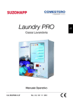
1. INTRODUZIONE – INTRODUCTION
Il presente manuale descrive un “Multi Control System” (MCS) per ventilconvettori
e/o unità di trattamento dell’aria.
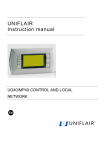
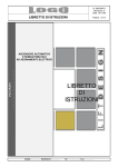
Il MCS (fig. 1) è composto da una scheda a microprocessore che può essere collegata
a un ricevitore (IRP) gestito da telecomando (IRT), oppure a un regolatore da esterno
(ETN) o in alternativa a un regolatore da incasso (FMH).
I regolatori ETN e FMH incorporano inoltre un ricevitore a infrarossi in grado di
interagire con il telecomando IRT.
La scheda controlla il funzionamento del ventilatore e della/e valvola/e.
Le velocità di funzionamento del ventilatore e la modalità estate/inverno, possono
essere cambiate manualmente o in automatico, in funzione della differenza di
temperatura tra set point e temperatura ambiente.
La scheda gestisce inoltre un termostato di minima che, in riscaldamento, dà il
consenso al ventilatore solo quando lo scambiatore ha raggiunto i 32 °C.
This manual describes a “Multi Control System” (MCS) for fan coil units and/or units
for air treatment.
The MCS (Pic. 1) includes an electronic board with microprocessor, an infrared
receiver (IRP) for an infrared remote control (IRT), or an external regulator (ETN) or
a built- in regulator (FMH).
ETN and FMH controllers also include an infrared receiver for the infrared remote
controller IRT.
The electronic board controls the fan speeds and the valve/s.
Fan speed and summer/winter mode, may be changed manually or automatically
according to the difference between the set point and the room temperature.
The electronic board controls also a minimum temperature thermostat (heating only)
which allows to start the fan, only when the temperature on the coil is higher than 32
°C.
4
1
5
2. DESCRIZIONE MCS – MCS DESCRIPTION
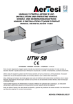
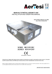
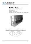
2.1. IL TELECOMANDO IRT – INFRARED CONTROLLER IRT
1
2
3
4
5
Orologio
Clock
Impostazione programma start/stop.
Start/stop set up
Temperatura di set point
Set point temperature
Velocità del ventilatore: min, med, max,
AUTO
Fan speeds: min, mid, max, AUTO
Modalità
di
funzionamento:
solo
ventilazione,
riscaldamento,
condizionamento, dry (non disponibile),
AUTO
Mode: only fan, heating, cooling, dry (not
available), AUTO
6
Tasto di spegnimento OFF
Power OFF
7
Tasto di selezione velocità del ventilatore
Fan speed selection button
8
Tasto impostazione orologio e timer
Timer and clock set up
9
Tasto selezione modalità di funzionamento
Mode button
10
Tasti impostazione temperatura e/o ora
Temperature and/or real time clock set up
2
6
11
Tasto di accensione On e invio del segnale
SEND al ricevitore
Start/sending button power on and signal
transmission
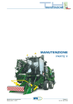
2.2. IL RICEVITORE IRP – INFRARED RECEIVER IRP
Il ricevitore va collegato alla scheda per mezzo dell’apposito connettore maschiato
The receiver must be connected to the electronic main board with its connector
12
Tasto accensione/spegnimento manuale
ON/OFF manual button
Led verde accesso - unità funzionante
13
Green led ON - unit running
Led giallo acceso - timer attivato
14
Yellow led ON – timer activated
Ricevitore infrarosso *
15
Infrared receiver *
3
* Assicurarsi che il ricevitore sia sempre libero per permettere la comunicazione con il telecomando
* Be sure that receiver is always free to allow the transmission with infrared remote control
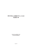
2.3. IL REGOLATORE ETN E FMH – CONTROLLER ETN AND FMH
4
16
17
Temperatura
ambiente.
Se
l’indicazione
lampeggia, viene visualizzata la temperatura di
set point.
Indicazione della modalità di funzionamento:
condizionamento, riscaldamento, ventilazione,
AUTO (Cool, Heat indicati contemporaneamente
sul display)
5
Room temperature. If the indication blinks, set
point temperature is displayed.
Mode: Cooling, heating, fan, AUTO (Cool, Heat
displayed together)
7
18
Velocità del ventilatore: HI, Med, Low, AUTO Fan speeds: Hi ,Mid, Low, AUTO (Hi, Mid, Low
(Hi, Med, Low indicati contemporaneamente)
displayed together)
19
* Aux (Segnale Timer attivato)
* Aux – Timer Activated
20
Acceso/Spento
ON/OFF
21
Tasti impostazione temperatura di set point.
Set point temperature buttons
22
Tasto di accensione e spegnimento
ON/OFF button
23
Tasto selezione modalità di funzionamento
Mode button
24
Tasto di selezione velocità del ventilatore
Fan speed button
* Il timer può essere inserito solo con il telecomando IRT. Se però l’unità viene spenta da ETN o FMH con
il tasto 22, il timer viene disattivato.
* Only the infrared remote controller IRT can set the timer, but if the unit is turned off using ETN or FMH
with button 22, the timer will be deactivated.
3. FUNZIONAMENTO TELECOMANDO IRT
IRT INFRARED REMOTE CONTROL FUNCTIONALITY
3.1 ACCENSIONE/SPEGNIMENTO – ON/OFF
Per accendere premere il tasto On/Send (11) del telecomando. Per spegnere premere
OFF (6).
Turn on On/Send (11) button on the infrared remote control. To turn off press OFF
button(6).
3.2 IMPOSTAZIONE DELL’OROLOGIO – CLOCK SET
Premere il tasto Select (8) finché sul display (2) compare la scritta CLOCK SET, con i
tasti (+) e (–) impostare l’ora, premere nuovamente il tasto (8) e con i tasti (+) e (-)
incrementare o decrementare i minuti, premere nuovamente Select (8) per concludere
l’impostazione dell’ora.
Press Select button (8) until CLOCK SET appears on the display (2), set the clock
with (+) and (-) buttons, press again button (8) and with (+) and (-) buttons, increase
or decrease the minutes, press again Select (8) to finish the clock set.
3.3 IMPOSTAZIONE DELLA TEMPERATURA – SET TEMPERATURE
Con i tasti (+) e (-) incrementare o decrementare la temperatura che verrà visualizzata
sul display (3). Al termine dell’operazione premere On/Send (11).
With (+) and (-) buttons increase or decrease the temperature, which will be
displayed (3). Press On/Send (11) to finish the settings.
8
3.4 MODALITA’ DI FUNZIONAMENTO – MODE SETTINGS
Premere il tasto Mode (9) ripetutamente, scegliere tra sola ventilazione, riscaldamento,
raffrescamento, cambio stagione automatico e dry (funzione non disponibile sul
presente dispositivo). Sul display (5) verranno evidenziati rispettivamente i simboli
. Al termine premere il tasto On/Send (11) per completare
l’impostazione.
Multi click mode button (9), choose among fan only, heating, cooling, auto change
and dry (not available for this system). The icons
displayed (5). Press On/Send (11) to finish the settings.
will be
3.5 REGOLAZIONE DEL VENTILATORE – FAN SETTINGS
Premere il tasto Fan (7) ripetutamente, scegliere tra velocità minima, media, massima
o selezione automatica. Sul display (4) verranno evidenziati rispettivamente i simboli.
. Al termine premere il tasto On/Send (11) per completare l’impostazione.
Nel funzionamento automatico il sistema seleziona la velocità più elevata,
all’aumentare della differenza di temperatura tra ambiente e set point.
Multi click fan button (7), choose between minimum, middle, maximum speed or
AUTO. The icons
will be displayed (4). Press On/Send (11) to finish the
settings. On the automatic speed selection, the system chooses the highest speed with
rising difference of temperature between the ambient and set point.
3.6 PROGRAMMAZIONE DEL TIMER – TIMER PROGRAM
Il sistema è dotato di un timer di accensione/spegnimento automatico giornaliero.
The system has a timer for daily automatic ON/OFF.
Istruzioni per l’inserimento del timer:
- Premere due volte il tasto Select (8), sul display (2) comparirà la scritta
lampeggiante PROGRAM START;
- con i tasti (+) e (-) incrementare o decrementare l’ora, premere nuovamente
Select (8) e nuovamente con (+) e (-) incrementare o decrementare i minuti;
- premere il tasto (8), sul display (2) comparirà la scritta PROGRAM STOP;
- con i tasti (+) e (-) incrementare o decrementare l’ora, premere nuovamente
Select (8) e nuovamente con (+) e (-) incrementare o decrementare i minuti;
9
TIMER
-
premere Select (8), sul display (2) lampeggerà l’icona con il timer
premendo il tasto (+), l’icona si colorerà di nero;
premere il tasto On/Send (11) per completare l’impostazione.
,
Sul ricevitore IRP si accenderà il led giallo (14), oppure sui controlli ETN e FMH
comparirà la scritta AUX (19).
Instructions for timer settings:
- Press twice Select button(8), PROGRAM START will be displayed (2)
blinking;
- with (+) and (-) buttons, increase or decrease the hour, press again Select
(8) and with (+) and (-) buttons, increase or decrease the minutes;
- press the button (8), PROGRAM STOP will be displayed (2);
- with (+) and (-) buttons, increase or decrease the hour, press again Select
(8) and with (+) and (-) buttons, increase or decrease the minutes;
TIMER
-
press Select (8), the timer icon
will be displayed (2), pressing (+) button,
the icon will be e black painted;
Press On/Send (11) to finish the settings.
On the receiver IRP the yellow led will light on (14), or AUX (19) will be displayed on
the ETN and FMH controls.
Istruzioni per lo spegnimento del timer:
- Premere quattro volte il tasto Select (8), sul display (2) lampeggerà l’icona
TIMER
-
evidenziato, premere il tasto (-) per deselezionare l’icona;
con il timer
premere il tasto On/Send (11) per completare l’impostazione.
Sul ricevitore si spegnerà il led giallo (14) oppure sui controlli ETN e FMH si
spegnerà la scritta AUX (19).
Instructions to turn the timer off:
TIMER
-
Press four times Select button (8), the timer icon
will blink black painted
on the display (2), press (-) button to unselect the icon;
Press On/Send (11) to finish the settings.
On the receiver the yellow led will light off (14), or AUX (19) will turn off on the ETN
and FMH controls.
Quando il timer è attivato, il programma di funzionamento impostato verrà
ripetuto automaticamente tutti i giorni.
When the timer is activated, the set program will be automatically repeated every
day.
10
4. UTILIZZO DEI REGOLATORI ETN E FMH
USE OF ETN AND FMH REGULATORS
4.1 ACCENSIONE/SPEGNIMENTO – ON/OFF
Per accendere o spegnere il dispositivo, premere il tasto ON/OFF (22) sul regolatore. Il
display (20) indica lo stato del sistema (acceso/spento).
Press ON/OFF (22) buttons to start or stop the system. The system state (ON or OFF)
will be displayed (20).
4.2 IMPOSTAZIONE DELLA TEMPERATURA – SET TEMPERATURE
Con i tasti (+) e (-) incrementare o decrementare la temperatura che verrà visualizzata
sul display (16).
With (+) and (-) buttons increase or decrease the temperature, which will be displayed
(16).
4.3 MODALITÀ DI FUNZIONAMENTO - MODE SETTINGS
Premere il tasto Mode (23): scegliere tra condizionamento, riscaldamento, cambio
stagione automatico. Sul display (17) verranno evidenziate rispettivamente le voci Cool
(condizionamento), Heat (riscaldamento), Cool/Heat (cambio stagione automatico).
Press mode button (23): choose among cooling, heating, auto change. The icons
COOL, HEAT, or COOL/HEAT will be displayed (17).
4.4 REGOLAZIONE DEL VENTILATORE - FAN SETTINGS
Premere il tasto Fan (24): scegliere tra velocità massima, media, minima o selezione
automatica. Sul display (18) verrà riportata la velocità impostata. Nel funzionamento
automatico il sistema seleziona la velocità più elevata, all’aumentare della differenza di
temperatura tra ambiente e set point. In questo caso sul display (18) compariranno
contemporaneamente le voci Hi, Med, Low.
Press Fan button (24): choose among minimum, middle, maximum speed or AUTO.
The speed selected will be displayed (18). On the automatic speed selection, the
system the highest speed chooses with rising difference of temperature between the
ambient and set point. In this case the icons Hi, Mid, Low will be displayed (18)
together.
I regolatori ETN e FMH possono essere comandati dal telecomando IRT (cf. cap. 3).
ETN and FMH regulators can be set by the IRT infrared remote control (s. ch. 3).
11
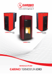
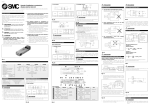
5. LA SCHEDA ELETTRONICA MIGA
ELECTRONIC BOARD MIGA
+12VDC
INFRARED
HEAT
RECEIVER
MICROCONTROLLER
DOOR
ETN - FMH
2
3
15
+5VDC
16
17
4
JMP2 UNSHORT = 2 pipe system
JMP2 SHORT = 4 pipe system
POWER
MAX
1/15
SUPPLY
MED
MIN
+12VDC
5/16
6
7
8/14
17
T4
ON/OFF
JMP2
T4
IRP
MIGA
HEAT/COOL
N
L1
230 V
T1
T1
T2
T2
T3
T3
IRP MUST BE CONNECTED
INSTEAD OF ETN OR FMH
T1- RETURN AIR SENSOR
T2- SUMMER / WINTER SENSOR (installed on the inlet pipe)
T3 > 32 °C in HEAT mode - Start Fan (installed on the coil)
6
Quando la scheda è configurata per controllare una sola valvola (impianto due tubi),
JMP2 deve essere aperto e la sonda T2 montata a contatto del tubo di alimentazione a
monte della valvola.
Con impianto due tubi la funzione stagionale si imposta sul funzionamento automatico
e non è possibile cambiare con i controlli tale settaggio.
When the electronic board is set to control only one valve (two pipes system), JMP2
must be unshort and the T2 probe must be installed with contact on the inlet pipe
before the valve.
With two pipes system summer/winter regulation is automatic and it’s not possible to
change any settings.
Passando da riscaldamento a condizionamento o al raggiungimento della temperatura
di set point, il ventilatore continua a funzionare per alcuni secondi.
When the system changes from heating to cooling or when the room temperature
reaches the set point, the fan runs again for some seconds.
12
6. CONNESSIONI ELETTRICHE
ELECTRICAL CONNECTIONS.
Proteggere l’unità con un opportuno interruttore magnetotermico o con un sezionatore
con fusibili.
Per tutti i collegamenti elettrici seguire gli schemi elettrici contenuti nel presente
manuale o quelli forniti a corredo delle macchine.
Preserve the unit with an opportune automatic switch or a switch with fuse.
For all the electrical connections, follow the wiring diagrams inside this manual or the
specific ones supplied whit the unit.
Prima di iniziare qualsiasi operazione assicurarsi che la linea di alimentazione generale
sia sezionata.
Before starting any works on the appliance, make sure that the main electrical power
supply line has been disconnected.
Fare eseguire i collegamenti elettrici solo da personale qualificato
Ensure that the electrical connections are performed exclusively by appropriately
qualified personnel
6.1. CABLAGGIO GRUPPO VENTILANTE – FAN MOTOR WIRING
(1)
MEA – Fancoil Size 03÷09
a
MEB – Fancoil Size 12÷15
Bianco White (Comune Common)
b1
Nero Black (max. alt.)
i
Nero Black (max.alt.)
b2
Nero Black (max. std.)
b
Grigio Grey (max. std.)
c3
Blu Blue (med. std.)
c
Blu Blue (med. std.)
MEA
c4
Blu Blue (med. alt.)
m
Arancio Orange (med. alt.)
d5
Rosso Red (min. std.)
d
Marrone Brown (min. std.)
d6
Rosso Red (min. alt.)
p
Rosso Red (min. alt.)
e
Giallo/Verde Yellow/Green (Terra Earth)
g
Cavo alimentazione Power supply cable
MEB
(1) Spostare sull’autotrasformatore i cavi b, c, d, secondo quanto sopra indicato, per ottenere le velocità
alternative sulle taglie 03÷09
(1) Move the cables b, c, d, on the autotransformer, according to the above to obtain the alternative speeds
for the sizes 03÷09
13
14
230V
50 Hz
{
L1
N
a b c d
ME
MIGA
MIN
MED
MAX
HEAT
QB+MIGA
+12VDC
HEAT/COOL
T1
T2
T2
+12VDC
T3
DOOR
T3
JMP2
JMP2 UNSHORT = 2 pipe system
JMP2 SHORT = 4 pipe system
T4
T4
17
8/14
7
6
5/16
4
3
2
1/15
16
17
IRP MUST BE CONNECTED
INSTEAD OF ETN OR FMH
IRP
ON/OFF
15
ETN - FMH
T3 > 32 °C in HEAT mode - Start Fan (installed on the coil)
T1- RETURN AIR SENSOR
T1
SUPPLY
POWER
+5VDC
MICROCONTROLLER
INFRARED
RECEIVER
6.2. CONTROLLO SOLA VENTILAZIONE – FAN CONTROL ONLY
230V
50 Hz
{
N
L1
a b c d
ME
MIGA
MIN
MED
MAX
HEAT
QB+MIGA+V2
+12VDC
HEAT/COOL
T1
T2
T2
+12VDC
T3
DOOR
RECEIVER
T3
JMP2
JMP2 UNSHORT = 2 pipe system
JMP2 SHORT = 4 pipe system
T4
T4
17
8/14
7
6
5/16
4
3
2
1/15
16
17
IRP MUST BE CONNECTED
INSTEAD OF ETN OR FMH
IRP
ON/OFF
15
ETN - FMH
T1- RETURN AIR SENSOR
T2- SUMMER / WINTER SENSOR (installed on the inlet pipe)
T3 > 32 °C in HEAT mode - Start Fan (installed on the coil)
T1
SUPPLY
POWER
+5VDC
MICROCONTROLLER
INFRARED
6.3. IMPIANTO DUE TUBI – TWO PIPES SYSTEM
15
16
230V
50 Hz
{
L1
N
a b c d
ME
MIGA
MIN
MED
MAX
HEAT
HEAT/COOL
T1
T2
T2
+12VDC
T3
DOOR
RECEIVER
INFRARED
T3
JMP2
JMP2 UNSHORT = 2 pipe system
JMP2 SHORT = 4 pipe system
T4
T4
17
8/14
7
6
5/16
4
3
2
1/15
16
17
IRP MUST BE CONNECTED
INSTEAD OF ETN OR FMH
IRP
ON/OFF
15
ETN - FMH
T3 > 32 °C in HEAT mode - Start Fan (installed on the coil)
T1- RETURN AIR SENSOR
T1
SUPPLY
POWER
+5VDC
MICROCONTROLLER
QB+MIGA+V4
+12VDC
6.4. IMPIANTO QUATTRO TUBI – FOUR PIPES SYSTEM
230V
50 Hz
TSR
EHR
L1
N
A1 A2
{
?
PE L1 N
EH
a b c d
ME
HEAT/COOL
T1
T2
T2
+12VDC
T3
DOOR
JMP2
T3
INFRARED
RECEIVER
JMP2 UNSHORT = 2 pipe system
JMP2 SHORT = 4 pipe system
T4
T4
17
8/14
7
6
5/16
4
3
2
1/15
16
17
IRP MUST BE CONNECTED
INSTEAD OF ETN OR FMH
IRP
ON/OFF
15
ETN - FMH
T3 > 32 °C in HEAT mode - Start Fan (installed on the coil)
T1- RETURN AIR SENSOR
T1
SUPPLY
POWER
+5VDC
MICROCONTROLLER
QB+MIGA+V2+EH+EHR
MIGA
MIN
MED
MAX
HEAT
+12VDC
6.5. IMPIANTO DUE TUBI E RISCALDATORE ELETTRICO
TWO PIPES SYSTEM AND ELECTRIC HEATER
17
7. MANUTENZIONE E CONTROLLI
CHECK AND MAINTENANCE
Per qualsiasi operazione di manutenzione togliere l’alimentazione elettrica
Disconnect the unit from the electrical supply before any maintenance
Assicurarsi che tendaggi e/o altri ostacoli non impediscano la
comunicazione tra telecomando e ricevitore.
Be sure that curtains, and/or obstructions doesn’t prevent the
communication between the infrared remote control and receiver.
Il telecomando utilizza due pile alcaline LR03. Aprire il coperchio sul retro
del telecomando. Sostituire le pile vecchie con quelle nuove. La durata
delle pile è di circa un anno in condizioni normali di utilizzo.
Infrared remote control uses two alkaline batteries LR03. Open the cover
on the back of the control. Substitute the old batteries with the new ones.
The battery life is about one year in normal using conditions.
Durante le operazioni di pulizia usare un panno asciutto e morbido per
togliere la polvere. Per togliere macchie usare solo un detergente neutro
diluito con acqua e asciugare con cura. Non usare liquidi infiammabili,
diluenti o sgrassanti che possono danneggiare le superfici di plastica.
During cleaning operations, use dry and soft cloth to remove dust.
To remove the spots use neutral detergent in diluted water, then dry with
care. Do not use flammable liquids, solvents or degreasing agents, which
may damage the plastic surfaces.
Evitare di versare liquidi, non esporre il telecomando al sole o a fonti
elevate di calore
Avoid to pour liquids, do not expose the infrared remote control to the
sunlight or to high heat source
Per nessun motivo le batterie devono essere danneggiate o gettate nel
fuoco.
The batteries mustn’t be damaged, or disposed in fire.
Non disperdere nell’ambiente le batterie dopo l’uso.
After use do not allows the batteries to be dispersed in the enviroment
Non versare acqua sull’unità per evitare danni elettrici o meccanici.
Do not pour water on the controls to avoid electrical or mechanical
damages.
18
8. PROCEDURA GUASTI – FAULT FINDING
Fare eseguire i controlli necessari solo a personale qualificato
Ensure that the various checks and inspections are performed exclusively by appropriately
qualified personnel
PROBLEMA PROBLEM
Il telecomando
correttamente o
segnale
non
non
PROBABILE CAUSA
PROBABLE CAUSE
funziona
invia il Batterie scariche
The infrared remote controller
doesn’t work correctly or doesn’t Exhausted batteries
send the signal
SOLUZIONE SOLUTION
Sostituire
le
batterie
telecomando (cf. cap. 8)
del
Change the batteries of the remote
infrared control (s. ch. 8)
Il ricevitore è coperto
Liberare il ricevitore
The infrared receiver is covered
Disclose the infrared receiver
Il segnale non arriva al ricevitore
La distanza tra telecomando e
Avvicinarsi al ricevitore
ricevitore è eccessiva
The sensor doesn’t receive the
signal
There is too much distance
between the infrared remote Move up to infrared receiver
control and the receiver too.
I led di segnale ON e Timer sul
ricevitore IRP (cf. fig. 3)
lampeggiano insieme
Le sonde T1 e T3 non sono Verificare la presenza delle sonde
presenti o mal collegate alla T1 e T3 e/o serrare i relativi
scheda
morsetti (cf. Fig. 6)
Verify if there are the probes T1
The probes TI and T3 are not
and T3 and/or clamp their
installed or bad connected
electrical terminals. (s. Pic. 6)
Verificare che JMP2 sia aperto,
Con impianto due tubi e JMP2
che la sonda sia collegata
aperto, non è presente o è mal
correttamente e i relativi morsetti
collegata la sonda T2
siano serrati (cf. Fig. 6).
The signal led ON and Timer on
the IRP receiver (s. Pic. 3) blink
together
Verify that JMP2 is open, the
With two pipes system and JMP2
probe is installed correctly and
unshort, the probe T2 is not
their electrical terminals are
installed or bad connected.
clamped. (s. Pic. 6)
19
I dati tecnici riportati nella presente documentazione non sono impegnativi.
AERTESI s.r.l. si riserva la facoltà di apportare in qualsiasi momento tutte le modifiche ritenute necessarie per il
miglioramento del prodotto
Technical data shown in this booklet are not binding.
AERTESI s.r.l shall have the right to introduce at any time whatever modifications considered necessary to the
improvement of the product
AERTESI s.r.l.
35026 Conselve PD – Italia
Via del Commercio, 2/B Z.I.
Tel. (+39) 049 9501109
Telefax (+39) 049 9500823
www.aertesi.com