1
UNIFLAIR
Instruction manual
UG40/MP40 CONTROL AND LOCAL
NETWORK
EN
UG40/MP40 CONTROL AND LOCAL NETWORK
UNIFLAIR SpA policy is one of continuous technological innovation.
The Company therefore reserves the right to amend any data herein
without prior notice.
Disposal: the product is made up of metal parts and plastic parts.
In reference to European Union directive 2002/96/EC issued on 27
January 2003 and the related national legislation, please note that:
WEEE cannot be disposed of as municipal waste and such waste
must be collected and disposed of separately;
The public or private waste collection systems defined by local
legislation must be used. In addition, the equipment can be
returned to the distributor at the end of its working life when
buying new equipment.
The equipment may contain hazardous substances: the improper
use or incorrect disposal of such may have negative effects on
human health and on the environment;
The symbol (crossed-out wheeled bin) shown on the product or
on the packaging and on the instruction sheet indicates that the
equipment has been introduced onto the market after 13 August
2005 and that it must be disposed of separately;
In the event of illegal disposal of electrical waste, the penalties
are specified by local disposal legislation.
Drafted by:
Checked by:
A.Munari
06/11/2008
2
06MC053@00B0120
06/11/2008
Approved by:
READ AND SAVE
THESE INSTRUCTIONS
UG40/MP40 CONTROL AND LOCAL NETWORK
CONTENTS
GENERAL FEATURES................................................................................................................................................ 5
USER INTERFACE...................................................................................................................................................... 6
LANGUAGE SELECTION............................................................................................................................................ 6
PROGRAM IDENTIFICATION..................................................................................................................................... 7
INFORMATION ON DISPLAY ..................................................................................................................................... 7
UNIT START UP CONDITIONS .................................................................................................................................. 8
SWITCHING UNIT ON AND OFF................................................................................................................................ 9
VARIATION OF PARAMETERS.................................................................................................................................. 9
VISUALISTAION OF THE UNIT STATE ................................................................................................................... 10
SWITCH ON UNIT/SWITCH OFF UNIT .................................................................................................................................. 10
INPUT/OUTPUT ...................................................................................................................................................................... 10
SETPOINTS ............................................................................................................................................................................ 10
ALARMS HISTORY ................................................................................................................................................................. 10
SOFTWARE INFO................................................................................................................................................................... 10
EXV VALVE STATUS .............................................................................................................................................................. 11
HUMIDIFIER STATUS............................................................................................................................................................. 11
MODEM GSM STATUS........................................................................................................................................................... 11
DESCRIPTION SETTINGS MENU............................................................................................................................ 12
OPERATIVE SETTINGS ......................................................................................................................................................... 12
SLEEP MODE ......................................................................................................................................................................... 13
HOURMETER SETTINGS....................................................................................................................................................... 13
EVACUATING THE HUMIDIFIER CYLINDER ........................................................................................................................ 14
ALARM RELAY SELECTION .................................................................................................................................................. 14
SERIAL/MODEM SETTINGS .................................................................................................................................................. 14
LAN SETTINGS....................................................................................................................................................................... 15
STAND-BY ROTAT. ALARMS ................................................................................................................................................. 15
CLOCK SETTINGS ................................................................................................................................................................. 15
DESCRIPTION SERVICE MENU .............................................................................................................................. 16
HARDWARE SETTINGS ......................................................................................................................................................... 16
SOFTWARE SETTINGS.......................................................................................................................................................... 20
SENSORS ADJUSTMENT ...................................................................................................................................................... 23
ALARM RESET MODE............................................................................................................................................................ 24
MEMORY OPERATIONS ........................................................................................................................................................ 24
EXV VALVE SETTINGS .......................................................................................................................................................... 25
MAIN SETTINGS ..................................................................................................................................................................... 25
ADVANCED SETTINGS .......................................................................................................................................................... 26
MANUAL CONTROL ............................................................................................................................................................... 27
UPDATING THE PROGRAM..................................................................................................................................... 28
ALARMS .................................................................................................................................................................... 29
ACTIVE ALARMS .................................................................................................................................................................... 29
ALARM HISTORY ................................................................................................................................................................... 29
DESCRIPTION OF ALARM EVENTS...................................................................................................................................... 29
EXCEEDING TEMPERATURE OR HUMIDITY LIMITS........................................................................................................... 30
OPTIONAL SENSOR OR DIGITAL INPUT ALARMS .............................................................................................................. 30
UNIT FUNCTION ALARMS ..................................................................................................................................................... 31
AFPS SENSOR ALARMS........................................................................................................................................................ 33
ELECTRONIC EXPANSION VALVE ALARMS (DX,TC,ES units only).................................................................................... 33
HUMIDIFIER ALARMS ............................................................................................................................................................ 34
SENSOR ALARMS .................................................................................................................................................................. 36
SERVICE NOTE ...................................................................................................................................................................... 36
“LAN” INTERUPTED ALARM .................................................................................................................................................. 37
SYSTEM ALARMS .................................................................................................................................................................. 37
ACCESS ALARMS .................................................................................................................................................................. 37
REMOTE ALARM SIGNALLING.............................................................................................................................................. 37
06MC053@00B0120
06/11/2008
3
UG40/MP40 CONTROL AND LOCAL NETWORK
DEFAULT VALUES ................................................................................................................................................... 38
AMBIENT TEMPERATURE REGULATION DIAGRAM ............................................................................................ 42
CHILLED WATER VERSION (CW) ......................................................................................................................................... 42
DIRECT EXPANSION VERSION (DX) .................................................................................................................................... 42
TWIN COOL VERSION (TC) ................................................................................................................................................... 43
ENERGY SAVING VERSION (ES) .......................................................................................................................................... 43
AMBIENT HUMIDITY REGULATION DIAGRAM ...................................................................................................... 44
GENERAL INFORMATION AND DEFINITIONS ....................................................................................................... 45
MOST COMMON PLAN NETWORK CONFIGURATIONS ....................................................................................... 46
PLAN CONNECTION BETWEEN PCO BOARDS .................................................................................................... 46
REMOTE TERMINAL CONNECTIONS..................................................................................................................... 47
MAXIMUM DISTANCES BETWEEN THE TERMINAL AND THE BOARD .............................................................................. 48
CABLE FOR LAN AND SUPERVISION CONNECTION ........................................................................................... 48
EXAMPLE OF A CONNECTION TO THE REMOTE TERMINAL FROM THE BOARD ........................................... 49
CONFIGURATION OF THE TERMINAL AND THE PCO BOARD ADDRESSING THE LOCAL NETWORK .......... 50
pCO: ASSIGNING THE LIST OF PRIVATE AND SHARED TERMINALS ............................................................................... 50
ASSIGNING THE LIST OF PRIVATE AND SHARED TERMINALS ........................................................................................ 51
LAN ADDRESS OF THE PCO BOARD..................................................................................................................... 51
TABLE FOR UNIT ADDRESS ................................................................................................................................................. 52
TABLE FOR TERMINAL AND PCO BOARD ADDRESSES .................................................................................................... 52
LAN PARAMETER CONFIGURATION ..................................................................................................................... 53
VISUALIZATION OF THE NETWORK FROM THE TERMINAL ............................................................................... 54
NOTE: ........................................................................................................................................................................ 55
4
06MC053@00B0120
06/11/2008
UG40/MP40 CONTROL AND LOCAL NETWORK
PART I:
UG40/MP40 CONTROL MANUAL
GENERAL FEATURES
The microprocessor control manages unit operation.
The control is essentially formed of:
a microprocessor control board, housed inside the electrical panel;
a graphic user interface.
Control board
Graphic user interface
The microprocessor control board contains the settings programme and all the stored operating parameters which
can be viewed and set on the user interface.
The control system has the following functions:
temperature and humidity control based on set-points programmed on the user interface;
possibility of setting a dual set-point for temperature (in both cooling and heating) and humidity (both when
dehumidifying and humidifying) which can be modified from a remote terminal;
complete alarm signalling system;
recording of all alarms;
alarm signal contacts configured on the user interface;
programming of automatic restart after power is restored;
remote unit switch on/off;
control of all timings for compressor operation and their switching on in rotation, to guarantee efficiency and
reliability;
setting of the electronic thermostat valve with signalling of any irregularities;
2 levels for password (settings and service);
possibility of communicating with a supervision system using the RS485 serial board, LON FTT10,by TREND
and PCOWEB (optional);
control of clock/date (clock card optional);
calculation of operating hours and the number of times the most important parts start up;
symbols appear to show the status of all unit parts with the possibility of viewing all the values recorded by the
probes connected to the control board;
differentiated
weekly
operating
times
for
switching
on/off
(with
optional
clock
board):
Weekdays – Days before holidays – Holidays
management of local network with possibility of programming the rotation of one or two stand-by units and the
operation of these units setback mode settings based on average temperatures;
"override" function which allows manual control of main parts without excluding possible remote control;
06MC053@00B0120
06/11/2008
5
UG40/MP40 CONTROL AND LOCAL NETWORK
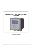
USER INTERFACE
The user interface is made up of:
1 backlit 132x64 pixel LCD display with buzzer;
6 backlit keys to move between and change parameters.
The microprocessor board is connected to the user interface by a 6 pole telephone cable with a RJ11 jack
connector.
ALARM: to view and reset alarms; flashes red when an alarm triggers
PRG: to enter configuration menu
ESC: to exit the screens
UP: to move around the menu
ENTER: to confirm
DOWN: to move around the menu
LANGUAGE SELECTION
Normally the display uses the language that has been defined by the regulation programme selected in the Flash
memory: IT = Italian, EN = English, DE = German, FR = French , SP = Spanish, RU = Russian and the possibility
of selecting a different language at any moment , by pressing on
12:22
26.3°C 55%
Esc
12:22
Inizializzazione
Attendere...
26.3°C 55%
and
Esc
.
12:22
Initiating ...
Please Wait
LAN01
12:22
Esc
26.3°C 55%
DEPART...
Attendre s.v.p.
LAN01
Esc
12:22
26.3°C 55%
Inicio
Espere...
LAN01
26.3°C 55%
Esc
Einschaltung...
Bitte warten
LAN01
Esc
12:22
26.3°C 55%
Esc
Hачало. Подождйте.
LAN01
LAN01
NOTE: With exception of the masks which are reserved for use by Assistance Technicians (“SERVICE MENU”),
which always appear in English.
6
06MC053@00B0120
06/11/2008
UG40/MP40 CONTROL AND LOCAL NETWORK
PROGRAM IDENTIFICATION
This manual describes the standard regulation characteristics for air conditioning units. Some characteristics of
special-order units may be different from those described in this manual.
Family
Release
Language
Update
LAN
Version
CDZNEW
v 2.7
GB
19/01/2009
LAN
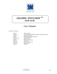
INFORMATION ON DISPLAY
The user interface normally displays a screen (hereafter referred to as “main screen”) with essential information on
the system state.
A
B
C
A displays the time, date (if the clock card is inserted) and number of the unit in the LAN network.
B displays room temperature and the percentage of humidity (if the probe is fitted).
C displays the information regarding unit status.
When the unit is not in operation, the following symbols can be seen on the display:
1.
2.
3.
4.
5.
6.
7.
8.
9.
10.
11.
12.
: press enter to switch on
: switched off by remote contact
: switched off by supervision system
: switch on with timer
: unit in automatic inversion cycle
: switch off by fire/smoke contact
: switch off by flooding contact
: setback mode
: unit switched off by air flow alarm
: unit switched off by general alarm
: manual shut down of the unit
: unit switched off by high air flow alarm
During operation, various types of symbols are displayed, which indicate the operating status of the unit. If it is
flashing, it indicates that there is a call in progress, but they are respecting the operating schedules (see the table
below).
SYMBOL
DESCRIPTION
Evaporator fan on
Alarm signalling also from the red flashing ALARM key
Mechanical cooling activated
Compressor status (if more than 1, the number is shown inside)
06MC053@00B0120
06/11/2008
7
UG40/MP40 CONTROL AND LOCAL NETWORK
Heaters on (if in stages, a number will appear by its side)
Cold water valve on
Hot water valve on
Hot gas valve on
Dehumidification on
Humidifier on
Generic alarm activated
Activation of time rotation
Manual switch-on
Unit manually ON
Manual switch-off
Unit switched on or off by remote terminal
Unit switched on by supervisory system
In versions Dx, Tc and Es, after the main screen, a second screen is displayed that indicates the number and
status of the compressors.
OFF
OFF
OFF
OFF
In versions CW and CW Dual Coil, the screen displayed indicates the number of cold water valves, their opening
and the water inlet and outlet temperature.
Room Temper.
°C 00.0
Deliv.Temp.
°C 00.0
COLD WATER VALVE
Room Temper.
°C 00.0
Deliv.Temp.
°C 00.0
COLD WATER VALVES
IN: 00.0
OUT: 00.0
IN: 00.0
OUT: 00.0
CW Version
IN: 00.0
OUT: 00.0
CW Dual Coil Version
UNIT START UP CONDITIONS
The following operations must be performed before the user can start the unit:
check that the light on the display is on (controller powered);
check that the red light on the
button is off (no alarms active);
check that the unit switches on after pressing the
8
button, alternatively:
check that the unit is started when the remote digital input ID2/4/6 contact is closed;
check that the unit is started by the supervisory system if this connected and configured (if serial card
inserted)
check that the unit is started by the daily or weekly time bands (if clock card inserted)
06MC053@00B0120
06/11/2008
UG40/MP40 CONTROL AND LOCAL NETWORK
SWITCHING UNIT ON AND OFF
The unit can be SWITCHED ON in any of the following ways:
1
Using the keypad: press ENTER to switch on the unit; a moving bar will appear
followed by fan symbol . To switch the unit off, go to first screen, press UP or DOWN then ENTER to
confirm SWITCH OFF UNIT. The symbol
will appear. Press ENTER again to confirm.
2
Automatic mode: the unit can be switched on by:
a remote on\off contact
a supervision system
(only serial card inserted)
a timer system
(only clock card inserted)
an automatic inversion cycle
If the unit is programmed to setback mode, it will automatically switch on even when it exceeds the set thermal
hygrometric temperature limits .
When in automatic mode, the unit can only be switched on by overriding it. Go to the first screen, press UP or
DOWN, confirm SWITCH ON UNIT and the symbol
will appear. Press ENTER to confirm, key in the
password and press ENTER again. The override switch on symbol
will appear on the first screen.
To SWITCH OFF go to the first screen, press UP or DOWN, confirm on the line SWITCH OFF UNIT. The symbol
will appear. Press ENTER to confirm, enter the password and press ENTER again. The override switch
off symbol
will appear on the first screen.
VARIATION OF PARAMETERS
Modification of set parameters and/or configuration in a subroutine (set point, differential…), is as follows:
1. proceed to screens in the programming method;
2. select with the
corner;
3. press the
or
buttons the screen that shows the parameter ; the cursor ( _) flashes in the top left
button to move the cursor to the parameter to be modified;
4. to vary the parameter value – this may be numerical or Boolean (YES/NO) – with the
(numeric values can be varied only within the set control limits);
5. finally press the
Esc
button.
To modify parameters in other screens press the
or
button
button to confirm the value.
To return to the previous screen, press the
press the
or
button until the cursor is at the start of the first line;
button to move to the desired screen.
06MC053@00B0120
06/11/2008
9
UG40/MP40 CONTROL AND LOCAL NETWORK
VISUALISTAION OF THE UNIT STATE
This program allows you to view information on the operation of the machine; however it is to be noted that only
the information or data relative to the chosen configuration appears.
From the main screen press the
or
button until reaching the menu that groups the items described
below, select the desired option and confirm by pressing
:
SWITCH ON UNIT/SWITCH OFF UNIT
This screen is used to switch the unit on and off. Based on the current status of the
unit, a different icon will be displayed, indicating the operation to be performed.
In the event of forced activation/deactivation, in automatic mode (remote contact,
supervisor, time bands), the settings password will be required for confirmation.
INPUT/OUTPUT
This screen and later, it is possible to verify the the state of the input and output
boards.
The initials visualised in the display are the same used to identify components
within the unit and in the relative documentation (electrical diagrams, refrigerant
diagrams, etc…).
SETPOINTS
This screen and the following are used to check the set point and the other
calibration parameters for the correct operation of the unit. These parameters are
read-only and as a result the values cannot be changed.
To set the values, access the parameters in programming mode and enter the
"SETTINGS" password.
All variables are pre-set in the factory so that the control functions correctly,
maintaining standard conditions the room temperature.
ALARMS HISTORY
/
Room Temper.
Room Rel.Hum.
Deliv. Temp.
Outdoor Temp.
Cold Water In
Cold Water Out
Hot Water
TEMPERATURE SETTINGS
Room Temperature:
Cooling Set
°C 00.0
Cool.Prop.Band
°C 00.0
Heating Set
Heat.Prop.Band
Summer
12:00
This screen and the following display the historical sequence of the alarms
activated; the microprocessor stores the last 100 events in its memory.
All the alarms saved can be read in sequence by pressing the UP or DOWN button;
if the clock card is fitted (optional), the date and time is recoded for each alarm
event.
°C 00.0
rH% 00
°C 00.0
°C 00.0
°C 00.0
°C 00.0
°C 00.0
01/01/06
°C 00.0
°C 00.0
AL01
Loss of Air Flow
Check Fan/Switch
SOFTWARE INFO
This screen and the following display the software version, bios, boot and unit serial
number.
This information is essential when adding a new unit to a group of units connected
in the LAN, as all the controllers must have the same program version.
When contacting a service centre, the version of the control program saved on the
control board must be indicated precisely.
10
06MC053@00B0120
06/11/2008
SW:cdznew 2.7 19-01-09
HW: pco1-medium
50Hz
BIOS: 00000
BOOT: 00000
SN: UCx 123456
UG40/MP40 CONTROL AND LOCAL NETWORK
EXV VALVE STATUS
This screen and the following display the information from the electronic expansion
valve driver boards.
HUMIDIFIER STATUS
This screen and the following display the information from the humidifier board.
MODEM GSM STATUS
This screen and the following display the information on the operating status of the
GSM MODEM and any error signals.
Power request
%000
Position
steps 000
Evap. Press.
Bar 00.0
Evap. Temp.
°C 00.0
Suct. Temp.
°C 00.0
SuperHeat
°C 37.0
SuperHeat Set
°C 06.0
Firmware HW:002
SW:038
Mode:- - - Status:- - - Steam Cap.
Kg/h
Saturated Cylinder:
High Level:
Conductiv.:
µS/cm
Meas. Current:
A
Nom. Current:
A
GSM MODEM STATUS
Stand-by Modem
Modem OK
Signal Field:
06MC053@00B0120
06/11/2008
00.0
N
N
0000
00.0
00.0
% 000
11
UG40/MP40 CONTROL AND LOCAL NETWORK
DESCRIPTION SETTINGS MENU
This part of the program is used to set the unit operating and signal parameters.
To access the section, press
pressing
pressing
or
Prg
, select the parameters menu and confirm, enter the settings password by
(the password is provided inside the envelope enclosed with this manual), and confirm by
.
OPERATIVE SETTINGS
All variables are pre-set in the factory so that the control functions correctly,
maintaining standard conditions in the room.
This screen visualised:
the probe used for temperature control;
cooling set point
cooling proportional band
heating set point (if a heating device is fitted)
heating proportional band
the status of the operating season (CW mode only)
This screen is displayed if the unit is connected to a system, called MASTER
CONTROL, which is used to manage the cooling installation by optimising the
operation of all the devices.
TEMPERATURE SETTINGS
Room Temperature:
Cooling Set
°C 00.0
Cool.Prop.Band
°C 0.0
Heating Set
°C 00.0
Heat.Prop.Band
°C 0.0
Status:
Summer
Estate
TEMPERATURE SETTINGS
Room Temperature:
Cooling Set
°C 00.0
Max.Offset A.F.
°C 0.0
Offset A.F.
Active Set
This screen displays the humidity control set point.
HUMIDITY SETTINGS
Dehumid.Set
rH%
Dehum.Prop.Band
rH%
Humid.Set
rH%
Humid.Prop.Band
rH%
This screen displays the second temperature and humidity control set point.
This screen displays whether the compensation set point is enabled, when the
outlet probe is used for room temperature control.
Graph of the compensation function
COMPENSATION SETPOINT
Enabled: No
Deliv.SP
Room T.
P1: 00.0°C
at 00.0°c
P2: 00.0°C
at 00.0°C
(P1 min value)
(P2 max value)
P2
P1
SP1
T2
12
T1
06MC053@00B0120
06/11/2008
00
00
00
00
2nd SET-POINT SETTINGS
2nd Cool.Set
°C 00.0
2nd Heating Set
°C 00.0
2nd Dehumid.Set
rH% 00
2nd Humid.Set
rH% 00
Outlet set point.
SP2
°C 00.0
°C 00.0
Room temp.
(return air)
UG40/MP40 CONTROL AND LOCAL NETWORK
This screen displays the activation set point for the high and low temperature and
humidity alarms in the room.
ALARMS SETTINGS
High Room Temp.
°C
Low Room Temp.
°C
High Humidity
rH%
Low Humidity
rH%
High Delivery T.
Enabled:
No
SLEEP MODE
The set back function, which can be either activated or de-activated by using the
control panel o BMS, consists of an automatic start-up of the stand-by unit – yet
powered – to exceed the following programmable limits for at least 30 seconds:
Minimum temperature;
Maximum temperature;
Minimum relative humidity (only with optional humidity sensor);
Maximum relative humidity (only with optional humidity sensor);
Intervention of the set back function, must control the room conditions – although
with larger tolerances – even if the whole system is in stand-by; it’s intervention
therefore is independent and not conditioned by signals from remote systems..
It is possible to program that during the set back function the fan runs in cycles to
allow that the temperature sensor is blown by the air within the room.
Intervention of the set back function is not considered as an alarm situation.
00
00
00
00
°C 00
SLEEP MODE SETTINGS
Sleep Mode Enable:
N
Min. Temp.:
°C 00.0
Max. Temp.:
°C 00.0
Min.Humid. Rel.:
rH% 00
Max.Humid.Rel.:
rH% 00
Fan Cyclical Start:
N
Cycle Time
min. 00
When the unit is in setback mode, in the STATUS MASK the symbol
is
displayed.
Normal operating conditions are re-set automatically when the temperature
values return to values set for [TEMP. MIN. + 2°C] and for [MAX. TEMP. - 2°C].
A minimum time of 15 minutes passes before the unit exits the set back mode; this
enables stable conditions to be reached and avoid continuous switching on and off
of the fans.
When normal conditions return, the
icon is displayed, alternating with
other icons depending on the previous status.
HOURMETER SETTINGS
This part of the programme enables the setting of maintenance intervals for the
components of the unit, establishing a threshold for operation hours. When the
device concerned reaches that limit, the microprocessor signals the maintenance
request, activating an alarm and displaying the symbol “ ” on the STATUS
SCREEN.
AIR FILTER
Total Run Hours
00000
Alarm Limit
h 00000
Reset:
--
Relate to the following unit components:
1. Air recycling fans ;
2. Compressors;
3. Electrical Heaters;
4. Air filters;
5. Humidifier
For each of them is possible
reading of the cumulative number of service hours;
setting of the SERVICE intervention threshold for maintenance; setting the
threshold at 0 inhibits the signalling of the SERVICE request;
zeroing of the timer (RESET = "OK/YES"), e.g. after the service intervention
and/or the replacement of the component.
Values can be changed only in the context of permitted setting fields.
06MC053@00B0120
06/11/2008
13
UG40/MP40 CONTROL AND LOCAL NETWORK
EVACUATING THE HUMIDIFIER CYLINDER
The steam cylinder needs to be periodically cleaned from limescale deposits;
before removing the cylinder for replacement or cleaning it is necessary to
completely drain all of the water from the boiler.
To carry out this operation it is necessary to access the masks and scroll through
them until the correct mask is shown:
press Enter and position the curser on the command which is to be selected;
press the UP or Down keys to display “ YES “ ad confirm by pressing Enter;
a message saying “Wait…” will appear on the screen;
wait for about 2 minutes, and the following message will be displayed “Cylinder
empty, Press Enter to Exit”;
open the magnetothermal general shut off switch of the humidifier and carry out
the cleaning/replacement of the cylinder;
only after having carried out all of the maintenance operations on the
cylinder press Enter to return to normal operating conditions of the humidifier.
Humidifier Cylinder
Maintenance:
Switch off/Empty:
Humidifier Cylinder
Maintenance:
Switch off/Empty:
Please wait...
N
S
…… after 2 minutes
Humidifier Cylinder
Maintenance:
EMPTY CILINDER
key enter to escape
ALARM RELAY SELECTION
This screen is used to change the status of the alarm signal contact, type “A” and
“B”
ALARM RELAYS
TYPE OF CONTACTS:
Alarm A Contact:
N.O.
Alarm B Contact:
N.O.
Legend:
N.O.: Normally Opened
N.C.: Normally Closed
This screen and the following are used to determine the digital output that signals
the alarm. The configuration of an alarm does not affect the action performed by
the controller (signal only on the display or shutdown of the device affected by the
alarm).
SERIAL/MODEM SETTINGS
SUPERVISION SYSTEM: a supervision system exchanges data via a serial cable
with the board of the unit that is commanded and controlled from remote: for this
purpose an optional Serial card is available which permits the interface to a net
RS232/RS485 for the transmission of data (see Supervision System manual).
Both for an external supervision system (with the possibility to turn ON/OFF the
unit) or with a closed-circuit monitoring system (only data transmission) the units
serial address must be set and the transmission speed.
This screen allows you to determine
the serial address of the unit connected to the supervision serial network (must
be the same as the serial address set in the supervision program);
the speed of data transmission (‘Vel. Ser.’): 1200, 2400, 4800 for RS232 or 1200,
2400, 4800, 9600 and 19200 for RS485.
the protocoll of comunication Standard or Modbus.
Note: with the LON protocol, set the serial address to 1 and the serial speed to
4800.
14
06MC053@00B0120
06/11/2008
ALARM RELAYS:
TYPE A/B ALARMS
Loss of Air Flow
Clogged Filters
Heaters Overheating
EEPROM Failure
Wrong Password
High Air Flow
A
A
A
A
A
A
SERIAL PARAMETERS
Serial Address:
001
Serial Speed:
1200
Protocol:
STANDARD
UG40/MP40 CONTROL AND LOCAL NETWORK
This screen and the following are used to define the parameters for the operation of
a GSM modem connected to the unit.
MODEM GSM SETUP
Total Phone Numbers:
0
Phone Number:
012345678
Modem Password:
Modem Rings:
Send SMS Enable:
LAN SETTINGS
For units with pCO control, the microprocessor is enabled for the automatic
management of a local network connected to more than one unit (up to a maximum
of ten), of which some in operation and others in stand-by (in stand-by) up to a
maximum of two units.
In the default configuration this is set to “NO LAN”.
Nonetheless, a single unit can operate temporarily if the address of the board is
equal to 1.
In this screen states:
the number of units in the local network has to be set (up to a maximum of
ten units);
the start-up of the stand-by unit in the event of malfunctions on a unit
connected in the LAN;
the rotation time to allow the workload to be shared between the units at
programmable time intervals. By setting cycle time = h 000, the controller
runs a test, rotating the units at two-minute intervals.
the possibility of have 1 or 2 units in standby;
the possibility to start the stand-by unit only in the event of alarms. The
rotation time is disabled.
The next screen, displayed only if the local network is set, gives the possibility to
control unit operation with a mean temperature measured in the room or with the
"local" value measured the sensor inside the unit:
Mode: Local: Unit control of the temperature and humidity values read by the
sensors in the unit
Mode: Mean: Unit control of the temperature and humidity values read by the
sensors in the active connected units in the local network.Whatever the difference
between the mean value and the sensor reading exceeds the value
"MEAN/LOC.DIFF." (default equal to 2°C), the control automatically exchanges
from the "MEAN" mode to the "LOCAL" mode.
0000
0
N
LAN SETTINGS
LAN Units Num.:
2
Automatic Switch-Over
of Stand-by Unit:
S
Cycle Time:
h 168
No.of Std-By Units:
1
Stand-By Unit Starting
Only On Alarm:
N
LAN SETTINGS
Temp./Hum.Control
Mode:
Local Values
Air Pressure Control
Mode: Local Values
The second parameter, displayed only if the AFPS system is configured, is used to
manage underfloor air pressure control, in local mode or with mean values.
STAND-BY ROTAT. ALARMS
This screen and the following are only displayed if the local network is configured,
and are used to manage the start-up of the stand-by unit if an alarm is activated.
ALARMS WHICH FORCE
ROTATION OF STAND-BY:
Loss of Air Flow
S
Clogged Filters
N
El.Heaters Overh.
S
EEPROM Failure
S
Wrong Password
N
High Air Flow
S
CLOCK SETTINGS
If the microprocessor is fitted with the optional clock circuit the date, time and
weekday is shown in the STATUS screen.
It is possible the time with:
start up and shut down of the unit according to timed program;
memorisation of the alarm events.
Setting of the time and date and the programming of the time bands is possible by
using the following screens dedicated.
06MC053@00B0120
06/11/2008
hh:mm
DD/MM/YY
Weekday
12:00
01/08/06
MO
15
UG40/MP40 CONTROL AND LOCAL NETWORK
DESCRIPTION SERVICE MENU
This part of the program is used to configure the devices installed on the unit and their operation; these operations
should be performed by qualified personnel.
Note that the manual describes the functions of the program in general and that based on the configuration set, the
fields and configuration screens may be enabled or disabled;
To access this section, press
or
Prg
, select SERVICE MENU and confirm, enter the service password by pressing
(the password is provided inside the envelope enclosed with this manual), and confirm by pressing
.
HARDWARE SETTINGS
The unit regulation program, after having cleared the memory if necessary, needs
to be “configured”, that is adapted to the unit in which it is installed; in this phase it
is necessary to define all the elements of the unit and that the microprocessor must
control.
As a rule this intervention is only required when the control is installed inside the
unit and therefore is carried out in the factory during final inspections; it can
however be necessary to intervene due to further unit modifications.
The screens that refer to configuration are in the English language and are
reserved for technicians:
Small Unit: Yes for Amico model; NO for Leonardo Evolution model;
Unit Type: identifies the type of unit between DX, CW, ES, TC;
Compressors: identifies the number of compressors installed on the unit (max 4);
Refrigerant Circuits: identifies the number of refrigerant circuits (max 2);
Compressor Type: identifies the type of compressor installed (Amico versions
only);
Heaters: identifies the number of operating stages of the electric heaters installed;
Hot Water Coil: enables operation of the hot water coil/valve;
Hot Gas Coil: enables operation of the hot gas coil/valve in the direct expansion
versions.
This screen is used to configure:
Exter.Hum. (on/off): enables operation of external humidifier via an on/off contact
from a digital output on the control board;
Humidif. 0-10V: enables operation of the external humidifier via the 0-10 Volt
analogue output Y2;
Valve: determines the type of expansion valve installed in the unit's refrigerant
circuit (parameter only available on the Amico model);
Dual Coil: enables the configuration for CW Dual Coil units;
Water Valve Type: determines the number of pins on the water valves in the CW
version;
This screen is used to configure analogue input 1 as an outlet temperature sensor
(Deliv.Temp.Sensor) or as the set point remote control (Setp.Remote Control).
This screen is used to configure analogue input 6 as an outlet temperature sensor
(Deliv.Temp.Sensor) or as a hot water sensor (Hot Water Sensor) or as an outlet
water temperature sensor (Water Out Sensor). Only on units with UpCO1 Small
controllers.
16
06MC053@00B0120
06/11/2008
Small Unit:
N
Unit Type:
DX
Compressors:
1
Refrigerant Circuits:
1
Compress.Type:
Scroll
Heaters:
1 Step
Hot Water Coil:
N
Hot Gas Coil:
N
Extern.Hum. (on/off):
N
Humidif. 0-10V:
N
Valve: Mechanical
Dual Coil:
N
Water Valve Type:
2Way
ANALOGIC INPUT 1
CONFIGURATION:
Deliv.Temp.Sensor:
Setp.Remote Control:
N
N
ANALOGIC INPUT 6
CONFIGURATION:
Deliv.Temp.Sensor:
Hot Water Sensor:
Water Out Sensor:
N
N
N
UG40/MP40 CONTROL AND LOCAL NETWORK
This screen is used to configure digital input 5 as:
No switch connected: no connection;
Summer/Winter Switch: change operating season in the CW version;
Water Flow Switch: water flow switch;
In the CW version, the operating season can be changed over, in alternative to the
digital input, from the user terminal, on the set point screen, or via serial connection
(supervisor).
This screen and the following are used to configure digital inputs 2/4/6.
This procedure allows the activation of digital inputs ID2-4-6 if optional kits are fitted
subsequently. The kits include fire and smoke sensors, flood sensors and high and
low outside temperature and humidity sensors that must be connected to a specific
input.
First check that the input is not already occupied, given that these are multifunction
inputs.
The table below shows a detailed description of each input, with the corresponding
function:
Digital Input 2
Not Used
1. Flooding Sensor (*)
2. Remote ON/OFF
3. Change Setpoint
4. User Configuration:
Alarm Signalling
DX/CW Switch-Over
Emergency Working
Digital Input 4
Not Used
1. Smoke-Fire Sensor
2. Remote ON/OFF
3. Change Setpoint
4. User Configuration:
Alarm Signalling
DX/CW Switch-Over
Emergency Working
ID5 Option SWITCH:
No Switch Connected
SUMMER/WINTER FUNCTION
BY USER TERMINAL:
Enable:
N
BY SERIAL PORT:
Enable:
N
DIGITAL INPUT 2
CONFIGURATION
Not Used
Digital Input 6
Not Used
1. External Limit Sensor
2. Remote ON/OFF
3. Change Setpoint
4. User Configuration:
Alarm Signalling
DX/CW Switch-Over
Emergency Working
(*) For AMICO units in the DX configuration with mechanical thermostatic valve, the same digital input will be used
for connection to both the flood sensor and the outside limit sensors, as input ID6 is used to control the status of
the low pressure switch in the refrigerant circuit. The alarm signal will also be different (see the section on ALARMS
FROM OPTIONAL SENSORS OR DIGITAL INPUTS)
If the digital input chosen is configured as USER CONFIGURATION, the following
screen is used to select the other functions:
Alarm signalling: alarm signal coming from a component outside of the unit;
DX/CW Switch-Over: external digital contact for changing over operating mode of
the unit (Twin Cool version only)
Emergency Working: signal coming from a component outside of the unit. The
DIGITAL INPUT 2
USER CONFIGURATION
Function:
Alarm Signalling
Contact:
Normally Closed
Status screen will display the
icon.
In addition, the status of the contact can be defined, N.O. or N.C.
This screen used to establish:
Fan Speed: rated fan speed;
Fan Supply: number of phases in the fan power supply
Dehumidification Fan Speed: rated speed in the dehumidification phase (for
Amico units with mechanical thermostatic valve only);
Modulation with Air Pressure Enabled: enables fan speed modulation with the
AFPS system;
Air Press. Transducer: determines whether the transducer is fitted on the unit;
06MC053@00B0120
06/11/2008
EVAPORATING FAN
Fan Speed:
% 000
Fan Supply:
3ph
DEHUMIDIFICATION
Fan Speed:
% 000
Modulation with Air
Pressure Enabled
N
Air Press.Transducer
N
17
UG40/MP40 CONTROL AND LOCAL NETWORK
This screen, available if the underfloor air pressure transducer (AFPS) is fitted, is
used to define:
Range Begin.: transducer reading start range value
Range End.: transducer reading end range value
Read Value: value read by the sensor
Delta: maximum variation of the input without activating the filter
Time: duration of the filter
Value: value read by the sensor
This screen, available if the underfloor air pressure transducer (AFPS) is fitted, is
used to define:
Minimum Speed-DX: minimum speed in version TC only
Minimum Speed: minimum fan control speed
Maximum Speed: maximum fan control speed
This screen, available if the underfloor air pressure transducer (AFPS) is fitted, is
used to define:
Set point: reference pressure value to be maintained by modulating the fan speed;
Dead Band: control dead band;
Regul. Band: control proportional band
Integral Time: integral time
Derivat. Time: derivative time
Air pressure: value read by the sensor
Evaporating Fan: evaporator fan control percentage
This screen, available if the underfloor air pressure transducer (AFPS) is fitted, is
used to define:
Alarm Level: low air pressure alarm activation threshold
Alarm Delay: low air pressure alarm activation delay time
This screen used to establish:
Enable: enables fan speed control associated with the opening of the water valve
(CW version only)
Minimum Speed: minimum fan control speed
Maximum Speed: maximum fan control speed
This screen used to establish which resources remain active in the event of
emergency operation, activated by a multifunction digital input ID2/4/6 configured
as USER CONFIGURATION - Emergency Working.
This screen, displayed only when the electronic expansion valve is fitted, is used to
establish the activation of the low pressure alarm by the pressure transducer
connected to the driver, setting:
Normal Limit: rated operating pressure;
Alarm Diff.: differential pressure due to the activation of alarm BP
Alarm Delay After Compr. ON: alarm BP activation delay time from compressor
ON
Alarm Delay Normal Working: alarm BP activation delay time during normal
operation
18
06MC053@00B0120
06/11/2008
AIR PRESS. TRANSDUCER
Range Begin.
Pa 000.0
Range End.
Pa 000.0
Read Value
Pa 000.0
INPUT FILTER
Delta
Pa
0.0
Time
s
00
Value
Pa 000.0
EVAPORATING FAN REGUL.
MODULATION
Minimum Speed-DX:
% 00
Minimun Speed:
% 00
Maximun Speed:
% 000
EVAPORATING FAN
Setpoint
Dead Band
Regul. Band
Integral Time
Derivat.Time
Air Pressure
Evaporating Fan
REGUL.
Pa 000.0
Pa 000.0
Pa 000.0
s 000
s 000
Pa 000.0
% 000
EVAPORATING FAN REGUL.
Alarm Level
Pa 000.0
Alarm Delay
s 000
EVAPORATING FAN
SPEED MODULATION WITH
VALVE OPENING
Enable:
Y
Minimun Speed:
% 00
Maximun Speed:
% 000
ACTIVE SOURCES DURING
EMERGENCY WORKING:
Fan:
Compressor:
Heaters:
Humidifier:
Y
Y
N
N
LOW PRESS.SETTINGS
Normal Limit:
bar 0.0
Alarm Diff.:
bar 0.0
Alarm Delay:
After Compr.ON:
s 000
Normal Working:
s 00
UG40/MP40 CONTROL AND LOCAL NETWORK
This screen, displayed only when the mechanical expansion valve is fitted, is used
to establish the activation of the low pressure alarm by the pressure switch
connected to ID6, setting:
Alarm Delay After Compr. ON: alarm BP activation delay time from compressor
ON
Alarm Delay Normal Working: alarm BP activation delay time during normal
operation
This screen is used to set the parameters for the operation of the humidifier inside
the unit, defining:
Humid. Model.: model installed;
V.: operating voltage;
TAM: model of current transformer used
Steam Cap.: number of kg of steam generated in 1 hour;
Nom.Current: rated current;
Max Steam Prod.: maximum rated percentage of steam to deliver
Timed drains enable: enables the procedure for draining the cylinder to avoid the
formation of scale inside
This screen, displayed only if the cylinder cleaning procedure is enabled, is used to
set:
Timed drains after number of startups: number of humidifier starts before
draining the cylinder;
Drain Time: cylinder drain procedure activation time
This screen, displayed only if the multifunction digital input is enabled, is used to
set:
Off Unit on Alarm: enables the shutdown of the unit if the flood alarm is activated;
Valve Closed on Al.: enables the closing of the water valve if the flood alarm is
activated;
This screen is used to set:
ON/OFF mode Via input contact: enables unit on/off via the multifunction digital
input;
ON/OFF mode only Via serial: enables unit on/off from BMS;
Motorized Damper: enables operation of the damper;
Opening Time: damper opening time. During this period the start of the fan and
the air flow alarm are ignored.
This screen is used to set:
Backlight Time: time the display backlighting remains on. This time also coincides
with the timeout for entering the password.
Buzzer Type: enables operation of the buzzer.
Time ON: time the buzzer remains on
This screen is used to set the mains frequency, automatically or manually.
06MC053@00B0120
06/11/2008
LOW PRESS.SETTINGS
Alarm Delay:
After Compr.ON:
s 000
Normal Working:
s 00
Humid.Mod: KUE1/S
V: 230/1
TAM 100-1turn
Steam Cap.:
Kg/h 00.0
Nom.Current:
A 00.0
Max.Steam Prod. %
000
(30-100% Nom.Cap.)
Timed Drains Enable:
N
HUMIDIFIER
TIMED DRAINS SETTING
Timed Drains After
Number of Startups:
00
Drain Time:
000
FLOODING ALARM
Off Unit on Alarm:
Valve Closed on Al.:
N
N
ON/OFF MODE:
Via Input Contact:
Only Via Serial:
N
N
Motorized Damper:
Opening Time
s
N
000
USER TERMINAL
Backlight Time:
s 000
Buzzer Type: Disabled
Time ON:
000
SUPPLY FREQUENCY
Automatic Set.
Frequency: 50 Hz
19
UG40/MP40 CONTROL AND LOCAL NETWORK
SOFTWARE SETTINGS
This screen is used to set:
Integral Time: integral time;
Anti-Hunting time constant: anti-swing time constant, that is, the time constant
for the temperature control action to avoid excessive temperature swings around
the set point. The higher the thermal inertia of the air-conditioned environment, the
higher the value needs to be set.
Dehumid.Control: enables dehumidification control (only if the humidity probe is
fitted)
Deliv.T. Low Limit: enables minimum air outlet temperature control.
Deliv.T. Set Limit: minimum air outlet temperature set point
This screen is used to set the type of control for the operation of the external
humidifier via the 0-10V signal sent by the board.
These screens are used to make the settings for the condensing circuit:
- on direct expansion units;
- on twin cool or energy saving units, during the mechanical cooling phase
(with only the compressors on).
The controller keeps the water temperature in the closed circuit at a suitable value
for condensation, between the set point and the set point + a fixed differential of
6°C.
ON Fan
Y
00
HUMIDIFIER 0-10V
SETTINGS
Regulation Type:
Proportional+Integral
Integral Time:
s 000
RADCOOLER SETTINGS
Temp.E.S.
°C 00.0
Set Point
°C 00.0
Radcooler Type:
On-Off
Room T. – Water T.
ES Setpoint:
°C 00.0
OFF
T water closed circuit
6°C
20
Deliv.T.Low Limit:
Deliv.T.Set Limit °C
ENERGY SAVING SETUP:
Room T.- Ext.T.
Radcooler Fan Speed
Change Set:
°C 00.0
RAD COOLER ON/OFF - Unit DX, DX/S, TC.
"Set Point"
(default = 28°C)
GENERAL SETTINGS
Integral Time:
s 0000
Anti-Hunting Time
Constant:
min 00
Dehumid.Control:
Y
06MC053@00B0120
06/11/2008
UG40/MP40 CONTROL AND LOCAL NETWORK
The temperature is controlled by managing the operation of the remote radiator
fans (”Rad-Cooler”) connected to the indoor unit; control can be:
- "On-Off": operation of the radiator fans is either on or off;
- modulating ("Modul"): control of the 0-10 V signal sent via analogue output Y1 to
manage the radiator speed.
RAD COOLER MODULATION
100% Fan Speed
10 V
Analogic
Output
0V
"Summer Temp."
(default = 28°C)
T water closed circuit
6°C
This screen is only available in the Twin-cool version and is used to manage the
settings for activating the changeover from mechanical cooling operation to
operation with chilled water.
CW ENABLE CONDITIONS
Activation Point at:
Water Temp. <
°C 00.0
Disactivation Point at
Activ.Point + °C 0.0
TWIN COOL. Unit
Chilled water valve
Compressor
Chilled water activ. set
point (default =7°C)
T water closed circuit
differential
fixed: 3°C
To avoid continuously alternating between the two operating modes, there is a
minimum interval of 30 minutes between two consecutive activations of the cold
water valve.
If the high room temperature limit is exceeded (default: 30°C), the unit automatically
switches from 'CW' operation to 'DX' operation, signalling the "High cold water
temperature or valve fault" alarm.
This screen is only available in the Twin-cool version and is used to enable CW
operation only if the alarm is activated in DX mode or via multifunction digital
contact or by BMS.
ENABLE CW WORKING:
Also On DX Alarm:
Only By ID Contact:
Only By Serial:
This screen is used to set the type of control in CW mode:
Room Temperature: the unit controls the return air temperature;
Delivery Temperature: the unit controls the outlet air temperature
CHILLED WATER SETUP
Regulation:
Room Temperature
06MC053@00B0120
06/11/2008
N
N
N
21
UG40/MP40 CONTROL AND LOCAL NETWORK
This screen is only available in the CW version and is used to establish the
dehumidification settings on chilled water units and calibrate the high temperature
alarm (only if the inlet water temperature probe is installed).
During the dehumidification phase, a special control function is activated, which
acts as follows:
- the controller sends the water chiller a request for water at a lower temperature to
allow dehumidification; this is done by instantly activating digital output DO7;
- the temperature probe located on the chilled water inlet is read;
- when the value read reaches the "SET POINT" as set on the screen, the valve is
opened to the maximum position settable on the following screen;
- if vice-versa the "SET POINT" is not reached, after 15 minutes an alarm is
signalled ("Chilled water too warm to dehumidify").
The temperature probe on the chilled water inlet is also used to control the "High
chilled water temp. " alarm, when the temperature exceeds the ‘HIGH TEMP.’ value
set on the screen, signalling a possible fault on the water chiller.
This screen is only available in the TC version and is used to enable the variation in
the chiller cooling set point for dehumidification.
This screen is only available in the CW Dual Coil version and is used to establish
the operating parameters for the water valves in circuits 1 and 2. The default
configuration is P1=100 % and P2= 0 %, that is, both valves open with the same
control ramp.
This screen is only available in the CW Dual Coil version with the pCOE connected
and is used to control the opening of the water valve, with three different solutions:
1. no open control;
2. via ID1 and ID2 on the pCOE board and establishing the status of the
contact;
3. via ID1 used as a switch over contact.
This screen is displayed only if the unit is fitted with both electric heaters
('ELECTRIC REHEAT' > 0) and a hot water coil ('HOT WATER COIL Yes').
It is used to set the set point for switching between these two heating systems.
Hot water coil
Heating
Hot water coil Activation
Set point (default =40°C)
T Hot water
differential
fixed: 5°C
22
06MC053@00B0120
06/11/2008
CHILLED WATER SETUP
Dehumidification Cycle
Start Set:
°C 00.0
High Water Temp. C1
Alarm Set:
°C 00.0
High Water Temp. C2
Alarm Set:
°C 00.0
CHILLED WATER SETUP
High Water Temperature
Alarm
Valves Forced: Y
Valve 1 Opened % 000
Valve 2 Opened % 000
CHILLED WATER SETUP
Dehumidification
Change Set Chiller
N
DUAL COIL PARAMETERS
P1 (valve 1):
P2 (valve 2):
100%
000%
DUAL COIL PARAMETERS
Valves Enabled By
DI1 and DI2 pCOE
Digital Input Config.:
V.1 ON with DI1:
V.2 ON with DI2:
HOT WATER COIL
ACTIVATION SET
Hot Water Temp.
°C 00
UG40/MP40 CONTROL AND LOCAL NETWORK
This screen concerns the behaviour during the initial transients and is used to set:
At Power On: delay in restarting the unit after a power failure; this is used to
prevent simultaneous starts in multiple installations. Units in the LAN automatically
feature a sequence start-up progressive (unit 1, unit 2, …) with 5 second intervals
between one unit and the next.
Regul. Transient: period of time between when the unit starts and control
commences; this is the initial period required for the control system to become
stable. In this period the reading of the air flow switch FS is also ignored; this allows
- above all on units with motor-driven dampers - the unit to start without the "No air
flow" alarm being activated.
Fan Off Delay: fan shutdown delay.
This screen is used to set:
T+H Al. Delay’: delay in signalling room alarms when starting the unit and in
normal operation.
Wrong Phases Sequence or Phase Loss: minimum unit OFF time if the alarm is
activated
This screen is used to change the access passwords:
- for the settings ("SETTINGS" password);
- for the configuration ("CONFIGURATIONS" password or "SERVICE" password).
DELAY SETTINGS
Unit Start UP Delay:
At Power On:
s 000
Regul. Transient:
s 000
(Also Flow/Flit Alarm)
Fan Off delay:
s 00
ALARM DELAY SETTINGS
Temp/Hum.Alarms Delay:
After Power ON:
min 00
Normal Working:
s 000
Wrong Phases Sequence
or Phase Loss
Min. OFF Time
s 000
PASSWORD SETUP
Settings Passw.:
00000
Service Passw.:
00000
Since access to the HARDWARE menu is denied unless the corresponding
password is known, the new password should be written down before changing the
old one.
This screen is used to set:
Anti-Hunting Time Constant: control time constant;
Delay Com. Error: delay for the communication error between the unit and the
Master Control;
Start Com. Trans.: initial communication transient
Master A.F.
Anti-Hunting Time
Constant:
min 00
Delay Com. Error
s 00
Start Com. Trans.
s 00
Com. Status:
Ok
The last line indicates the status of communication between the unit and the Master
Control.
SENSORS ADJUSTMENT
This screen and later, it is allow to correct the reading of the temperature sensors
("ROOM TEMP.", "EXT. AIR TEMP.", "DELIVERY TEMP.", "CHILLED WATER
CLOSED and HOT WATER", "ROOM HUMIDITY") in case a difference between
the measured value of the sensor and the effective value is detected, measured
with a precision instrument.
The adjustments can be done at intervals of 0.1 °C and the maximum adjustment
possible is between -9.9°C and +9.9 °C.
ROOM TEMP.SENSOR
Read Value
Adjustment
°C 00.0
°C 0.0
The Read value is the measurement transmitted by the sensor already corrected.
The adjustment ("Adjustment") is the quantity that needs to be added or
subtracted to obtain the correct value, measured with a precision instrument.
06MC053@00B0120
06/11/2008
23
UG40/MP40 CONTROL AND LOCAL NETWORK
ALARM RESET MODE
This screen and the following are used to set the alarm resets to manual or
automatic;
ALARM RESET MODE
(M = Manual/ A = Auto)
High Room Temp.
A
Low Room Temp.
A
High Room Humidity
A
Low Room Humidity
A
High Water Temp.
A
High Wat.T.to Dehum.
A
M
MEMORY OPERATIONS
This screen manages the data contained in the microprocessor Flash EPROM.
PROGRAM SET UP. This is an operation that is carried out the event of Flash
EPROM substitution. It can be useful if data is ‘damaged’ (set-point, configurations,
etc.) as it is possible to clean the memory (including data relative to the unit
HARDWARE configuration); where all the set point values reset automatically
(see paragraph "DEFAULT VALUES").
After this operation it is necessary to re-configure the control and to proceed to the
setting of the set-point when different from those of the default.
IMPORTANT: when modified also if only a parameter of the configuration (and
therefore also for Flash EPROM substitution) it is necessary to empty also the
RAM memory by cutting off the power to the control for a few seconds.
AL. PAGE CLEAR-UP: historical alarms cleaning permits to cancel the last 100
alarm event saved in the memory.
HARDWARE SET UP Possibility to carry out an automatic identification of the
devices connected to the control. This operation is useful when an optional device
must be connected to the board, or when substituting a sensor or when the display
shows "NC" as the reading of the temperature sensor.
24
06MC053@00B0120
06/11/2008
Program Set up
Al.Page Clear-up
Hardware Set up
N
N
N
UG40/MP40 CONTROL AND LOCAL NETWORK
EXV VALVE SETTINGS
This screen and the following are only displayed if the electronic expansion valve is
configured, and are used to access the valve operating settings.
MAIN SETTINGS
ADVANCED SETTINGS
MAIN SETTINGS
This screen is used to set:
Valve Type: model of electronic valve used:
Refrigerant: type of refrigerant gas used;
Low SH Protection: enables low superheating protection
MOP Protection: enables maximum operating pressure protection
MOP Set: maximum operating pressure set point
LOP Protection: enables minimum operating pressure protection
LOP Set: minimum operating pressure set point
This screen is used to set:
Range Begin.: start scale for the evaporation pressure transducer reading;
Range Ending: end scale for the evaporation pressure transducer reading;
Read Value: the value read, i.e. the measurement sent by the probe.
Valve Type: E2V
Refrigerant: R407C
ACTIVE FUNCTION
Low SH Protection:
Y
MOP Protection:
Y
MOP Set:
°C 00.0
LOP Protection:
N
LOP Set:
°C 00.0
PRESSURE PROBE RANGE
Range Begin.:
bar 00.0
Range Ending:
bar 00.0
Read Value:
bar 00.0
This screen is used to set:
Press.Offset: the correction, i.e. the value added or subtracted to achieve the
correct reading, measured using a precision instrument.
Read Value: the value read, i.e. the measurement sent by the transducer, already
corrected.
PRESSURE PROBES OFFSET
CIRCUIT 1:
Press.Offset:
bar 0.0
Read Value:
bar 00.0
CIRCUIT 2:
Press.Offset:
bar 0.0
Read Value:
bar 00.0
This screen is used to set:
Temp.Offset: the correction, i.e. the value added or subtracted to achieve the
correct reading, measured using a precision instrument.
Read Value: the value read, i.e. the measurement sent by the probe, already
corrected.
TEMP. PROBE OFFSET
CIRCUIT 1:
Temp.Offset:
bar 0.0
Read Value:
bar 00.0
CIRCUIT 2:
Temp.Offset:
bar 0.0
Read Value:
bar 00.0
This screen is used to set:
Low Superheat: low superheat alarm activation delay time;
High Suct.Temp.: high suction temperature alarm activation delay time;
LOP Failure: minimum operating pressure alarm activation delay time;
MOP Failure: maximum operating pressure alarm activation delay time;
Press.Probe Failure After Compr. ON: pressure probe disconnected or not
working alarm activation delay time after the compressor starts;
Press.Probe Failure At Normal Work.: pressure probe disconnected or not
working alarm activation delay time in normal operation;
06MC053@00B0120
06/11/2008
ALARM DELAY
Low SuperHeat:
s 0000
High Suct.Temp.:
s 0000
LOP Failure:
s 0000
MOP Failure:
s 0000
Press.Probe Failure:
After Compr.ON:
s 00
At Normal Work.:
s 00
25
UG40/MP40 CONTROL AND LOCAL NETWORK
This screen is used to manually set the opening steps for the electronic expansion
valve.
This screen is used to set the opening steps for the electronic expansion valve
when there is no cooling request.
ADVANCED SETTINGS
CIRCUIT 1
Manual Open. Step:
MANUAL MODE:
0000
N
CIRCUIT 2
Manual Open. Step:
MANUAL MODE:
0000
N
CIRCUIT 1
CLOSING BACKSTEPS:
000
CIRCUIT 2
CLOSING BACKSTEPS:
000
SuperHeat Set
°C 00.0
(Auto: 00.0)
Dead Zone:
°C 0.0
(Auto: 0.0)
Prop.Gain:
00.0
(Auto: 00.0)
Integral Time:
s 000
(Auto: 000)
This screen is used to set:
Superheat Set: superheat set point;
Dead Zone: dead band;
Prop.Gain: proportional gain;
Integral Time: integral time.
This screen is used to set:
Derivat. Time: derivative time;
Max Suction temp.: maximum suction temperature;
Circ./EEV Ratio: relationship of the refrigerant circuit to the type of electronic valve
inserted.
This screen is used to set:
Low limit: low superheat minimum limit;
Integral Time: integral time.
Derivat. Time:
s 00.0
(Auto:00.0)
Max Suction Temp.:
°C 00.0
(Auto:00.0)
Circ./EEV Ratio:
LOW SHEAT PROTECTION
Low Limit:
°C 00.0
(Auto: 00.0)
Integral Time:
This screen is used to set:
Start-up delay: maximum operating pressure protection delay time when starting;
Integral Time: integral time;
LOP Integral Time: minimum operating pressure protection integral time
This screen is used to set:
Dehum.SH Set: superheat set point in the dehumidification phase;
LOP Limit: minimum operating pressure limit in the dehumidification phase.
26
000
06MC053@00B0120
06/11/2008
s 00.0
(Auto:00.0)
MOP PROTECTION
Start-Up delay:
s 000
(Auto:000)
Integral Time:
s 00.0
(Auto:00.0)
LOP PROTECTION
LOP Int.Time:
s 00.0
(Auto:00.0)
DEHUMID.SETTINGS
Dehum.SH Set:
°C 00.0
LOP Limit:
°C 00.0
UG40/MP40 CONTROL AND LOCAL NETWORK
MANUAL CONTROL
During normal operation, all the components fitted on the unit are managed automatically, nonetheless, to assist
maintenance and checks or in cases of emergency, the individual components can be activated manually - and
independently of the control process.
unit fan (Unit start-Up);
compressor 1/2/3/4 (Compressor 1/2/3/4);
(on CW units) analogue output 0/1 (Y0/Y1Ramp %);
dehumidification function (Dehumidification);
first electric heater stage (Reheating 1);
second electric heater stage (Reheating 2);
activate the 0/1 analogue output on DX, TC, ES units (Y0/Y1Ramp);
The safety devices are also active during manual operation
AUTOMATIC / MANUAL OPERATING MODES
To change the operating mode of a component, simply move the cursor to the
corresponding line, press
or
to change from automatic ("No") to manual
("Yes") or vice-versa, and confirm by pressing
.
Manual Override:
Unit Start-Up
Compressor 1
Compressor 2
Compressor 3
Compressor 4
Dehumidification
Humidifier – Drain
N
N
N
N
N
N
N
Manual Override:
Reheating 1
Reheating 2
N
N
The next screen can also be used to set, as a percentage, the opening of the
devices connected to analogue outputs Y1, Y2 and Y3.
If the pCOE is connected in the CW Dual version Coil, the setting of analogue
output Y1 will also be displayed.
Manual Override:
Y1 Ramp
% 000
Y2 Ramp
% 000
Y3 Ramp
% 000
When activating one or more components manually, the STATUS screen will show
Dual Coil – pCOE
Y1 Ramp
% 000
the
icon.
06MC053@00B0120
06/11/2008
27
UG40/MP40 CONTROL AND LOCAL NETWORK
UPDATING THE PROGRAM
The following systems can be used to update and acquire the firmware and the logs on the pCO controllers:
1. Winload;
2. SmartKey programming key.
Winload
On all pCO sistema controllers the resident software can be updated using a PC. For this purpose, UNIFLAIR
S.p.A. provides the WinLoad32.exe program and a serial converter with USB-RS485 output to connect to the pCO
via the telephone connector. The special driver must be installed on the PC, this too supplied by UNIFLAIR S.p.A.
The WinLoad32.exe program is installed together with the pCO Manager program. The installation includes, as well
as WinLoad32.exe, the user manual and the driver for the USB-RS485 converter.
SmartKey
The new SMARTKEY programming key is used to emulate the operation of the parallel programming key on pCO
models where this is not available (pCOXS, pCO3), with the sole exception of the BOOT, which is not loaded by
the SMARTKEY. Specifically, the key can clone the contents of a pCO and then copy these to another pCO that is
identical to the first, via the telephone connector on the terminals (the pLAN must be disconnected). As well as this,
the key can also copy the data logged by a series of pCO devices to a PC. On the PC, using the “SMARTKEY
PROGRAMMER”, the key can be configured to run certain operations: acquire logs, program applications, program
the Bios, etc.
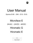
Below are some pictures showing examples of downloading the program to the pCO control board.
Inside the kit is a CD and a manual with step-by-step explanations of how to best use these accessories.
The program files, on the other hand, will be sent by e-mail or CD, indicating the name of the application when
ordering.
28
06MC053@00B0120
06/11/2008
UG40/MP40 CONTROL AND LOCAL NETWORK
ALARMS
ACTIVE ALARMS
By pressing this
button the alarm will be silenced and a description of the alarm will be displayed. If the cause
of the alarm has been eliminated, the last alarm message can be reset by pressing the
button for several
seconds; the red light on the key will turn off immediately. If the cause of the alarm has not been eliminated, the
alarm buzzer will be activated again.
ALARM HISTORY
In order to be able to reconstruct the alarm history sequence, the microprocessor holds 100 alarm events in its
memory. All of the alarms which are memorized can be read in series by entering the status masks by pressing the
UP and DOWN keys and choosing the ALARM HISTORY option; if there is a clock card (optional) the time and
date will also be recorded of each alarm event.
12:00
AL01
01/01/06
Loss of Air Flow
The alarms activated when the counter threshold is exceeded are not memorized and therefore are not able to be
read.
DESCRIPTION OF ALARM EVENTS
All of the possible alarm messages which can be displayed on the user terminal are shown below.
For active alarms (and therefore not memorized in the alarm history sequence), some possible suggestions will
appear for solving the problem in the last two lines of the display.
Incorrect Phase Sequence
The Scroll compressor must rotate in the correct direction otherwise there
will be a loss of efficiency. In single units with three-phase power supply it is
possible that the phase sequence of the network forces a rotation direction
is different to that which has been planned; in this case, as soon as the unit
is connected to the power supply, the microprocessor immediately enters
into an alarm state blocking any other type of operation. In this case,
disconnect the power supply and invert the two phases of the power supply.
Power Supply Return Signal
When the power supply is restored following a break in the power supply
the control memorizes the mask which is shown here in the alarm history
sequence.
06MC053@00B0120
06/11/2008
Wrong Power Phases
Sequence: Please
Change-Over 2 Phases
12:00
01/01/06
Power Back
After Failure
29
UG40/MP40 CONTROL AND LOCAL NETWORK
EXCEEDING TEMPERATURE OR HUMIDITY LIMITS
These are alarms which are activated when the thermohygrometric limits which have been set are exceeded (see
the Operating Parameters mask).
Signal only. This can be delayed during the unit start-up phase (the default
delay is 15 minutes)
Room Temperature
Above Max. Limit
Signal only. This can be delayed during the unit start-up phase (the default
delay is 15 minutes)
Room Temperature
Below Min. Limit
Signal only. This can be delayed during the unit start-up phase (the default
delay is 15 minutes)
Delivery
Air Temperature
Above Max.Limit
Signal only. This can be delayed during the unit start-up phase (the default
delay is 15 minutes).
Room Rel. Humidity
Above Max. Limit
Signal only. This can be delayed during the unit start-up phase (the default
delay is 15 minutes)
Room Rel. Humidity
Below Min. Limit
OPTIONAL SENSOR OR DIGITAL INPUT ALARMS
These alarms are connected to the optional sensors and/or the configurable digital inputs (see the Hardware
Settings mask).
Signal only.
(For Leonardo Evolution units and Amico CW units)
Activated by the Smoke / Fire sensors and always causes the unit to switch
off.
30
06MC053@00B0120
06/11/2008
Room Limits Exceeded
(by Ext.Sensors)
Presence of
SMOKE/FIRE
UG40/MP40 CONTROL AND LOCAL NETWORK
Activated by the flooding control module or from the condensing discharge
pump alarm contact; only causes the unit to switch off if it has been chosen
as a second level alarm, but it does not activate the stand-by unit.
Activated by a digital input configured as “Alarm Signalling”.
(ID2, ID4, ID6)
Activated by the flooding control module, the external temperature or
humidity sensors.
(For Amico DX units)
Flood Alarm
Digital input
Alarm 2
Flood Alarm
or Room Lim. Exceeded
(by Ext.Sensors)
UNIT FUNCTION ALARMS
These are alarms connected to the unit components and which are caused by the intervention of a protection
device.
Fan alarm: Activated by the differential air flow pressure switch (FS).
Causes all of the devices to switch off (compressors, electrical heaters,
humidifier, fans).
Activated by the differential high air flow (FSA).
Causes all of the devices to switch off (compressors, electrical heaters,
humidifier, fans).
Activated by the differential dirty filter pressure switch (PFS); only causes
an alarm signal, without unit operation being affected. Indicates that the air
filter needs to be cleaned or replaced.
Alarm signal activated by from the safety thermostat (TSR); causes the
electrical heaters to switch off.
06MC053@00B0120
06/11/2008
Loss of Air Flow
Check Fan/Switch
High Air Flow
Clogged Filters
Clean or Replace
Filter Element
Heaters Overheating
or Heaters Contactor
Failed
31
UG40/MP40 CONTROL AND LOCAL NETWORK
DX, ES, TC units only. Causes the compressors to switch off on the circuit
indicated (1 or 2). Check the refrigerant circuit and/or refrigerant charge and
high pressure switch.
High Condensing
Pressure or Compr.
Contactor Failed
DX, ES, TC units only. Causes the compressors to switch off on the circuit
indicated (1 or 2). Check the refrigerant circuit and/or refrigerant charge and
high pressure switch. Also specifies the number of the circuit.
Low Evaporating
Pressure
CW units only. Activated by the chilled water air flow pressure switch which
signals a lack of water within the hydraulic circuit.
Loss of Chiller
Water Flow
CW units only (signal only). Activated by the chilled water temperature
sensor when the set point value is not reached within 15 minutes of the
dehumidification request.
Water too Warm to
get Dehumidification
CW units only (signal only). Activated by the chilled water temperature
sensor when the high temperature limit is exceeded.
High Chilled Water
Temperature
TC units only: causes the changeover from chilled water operation (CW) to
direct expansion (DX). It is also displayed when the ambient temperature
sensor detects that the limit set has been exceeded for the first time.
CW Valve Failure or
Water Flow too Low
Active on a loss in communication between the UpCO1 control board and
the UpCOE expansion board in the Cooling Water Dual Coil version
Dual Coil:
Expansion Board
Not Connected
Active when the controller cannot automatically detect the mains frequency.
Supply Frequency
Not Detected
32
06MC053@00B0120
06/11/2008
UG40/MP40 CONTROL AND LOCAL NETWORK
AFPS SENSOR ALARMS
Alarms relating to the AFPS system.
Active in the event of a fault on the underfloor sensor, with the evaporator
fan activated at maximum speed.
Air Pressure Sensor
Failed/Disconnected
Active when, after the threshold and the alarm activation delay time set
have been exceeded, there is low underfloor air pressure, with the
evaporator fan activated at maximum speed.
Low Air
Pressure
Active on a loss in communication between the UpCO1 control board and
the UpCOE expansion board in the AFPS system
AFPS:
Expansion Board
Not Connected
ELECTRONIC EXPANSION VALVE ALARMS (DX,TC,ES units only)
These are alarms which are connected to the driver of the EVD400 electronic expansion valve, causing the
compressor/s to switch off.
Activated when there is low evaporation pressure, or rather, when the LOP
is lower than the threshold which has been set, for a period which is longer
than the Alarms Delay LOP. Also specifies the number of the circuit.
EXV LOP Protection
Failed
Activated when there is excessive evaporation pressure, or rather, when the
MOP is higher than the threshold which has been set, for a period longer
than the Alarms Delay MOP. Also specifies the number of the circuit.
EXV MOP Protection
Failed
Activated following an error in the signal given by the low pressure
ratiometric pressure transducer or a lack of working pressure caused by the
compressors not being switched on.
Activated following an error in the signal given by the NTC low pressure
temperature sensor for the superheating reading. Also specifies the number
of the circuit.
06MC053@00B0120
06/11/2008
EXV Valve Driver:
Pressure Probe Error
or Compressor Failed
EXV Valve Driver:
Temp.Probe Error.
33
UG40/MP40 CONTROL AND LOCAL NETWORK
Activated following an error in the EEPROM memory of the driver. Also
specifies the number of the circuit.
Activated when there is low superheating, for a period which is longer than
the Alarms Delay Low SH. Also specifies the number of the circuit.
Activated following an error in the tLAN connection between the EVD400
driver and the PCO1 control board. Also specifies the number of the circuit.
Activated following a temperature measurement taken by the EVD400
sensor, which is higher than the threshold value set in the High SH. Also
specifies the number of the circuit.
This is only displayed in the alarm history when the driver is without power
for more than 5 seconds when the compressor is operating. Also specifies
the number of the circuit.
EXV Valve Driver:
Eeprom error
EXV Valve Driver:
Low Superheat
EXV Valve Driver:
Driver Not Connected
EXV Valve Driver:
High Suction
Temperature
Voltage Dip
HUMIDIFIER ALARMS
Active when the corresponding threshold is exceeded for more than an
hour, or alternatively instantly when the conductivity of the supply water is
three times higher than the corresponding high conductivity threshold.
Disables operation of the humidifier.
This may be shown in the following three cases:
1. drain to dilute, if a sufficient decrease in current is not measured
and if the evaporation time is below certain limits;
2. wash-antifoam status, if at the end of the drain cycle the water
touches the high level electrodes;
3. pre-wash status, if during the period in which 10 minutes of
simultaneous drain and fill cycles are performed, the water touches
the high level electrodes.
34
06MC053@00B0120
06/11/2008
HUMIDIFIER:
High Conductivity of
Feeding Water
(> 0000µS/cm)
(Humidifier Lock)
HUMIDIFIER:
Drain Malfunction
(Humidifier Lock)
UG40/MP40 CONTROL AND LOCAL NETWORK
Active if the water touches the high level electrodes in one of the following
cases:
1. the unit is disabled or shutdown (remote control switch, fill and drain
OFF);
2. before the start of the first pre-wash cycle (consisting of 10 minutes
of simultaneous drain and fill cycles)
The current running through the electrodes is checked constantly during the
operation of the humidifier. Nonetheless, whenever the unit restarts
following a production request, the current is checked to see if it exceeds a
precise current profile.
This alarm is displayed if the following events occur in sequence:
in the fill phase
the difference between the current measured and the start fill
current is lower than a threshold calculated on the current target or
in steady operation
the water touches the high level electrodes
the current measured is lower than a threshold calculated on the
rated current.
If during low production (after a drain due to high level) the end fill current is
lower than a certain threshold calculated on the rated current.
Number of cylinder operating hours exceeded. Replace the cylinder
This may be shown in the following two cases:
1. Fill phase:
a. if the maximum fill time has elapsed
b. if the current measured does not reflect normal fill operation
2. Pre-wash status:
a. if during the fill phase the water level does not touch the
high level electrodes within the maximum fill time
HUMIDIFIER:
Bottle Full of Water
(Humidifier Lock)
HUMIDIFIER:
High Current
(Humidifier Lock)
HUMIDIFIER:
Low Current
(Humidifier Lock)
HUMIDIFIER:
Low Production
(Humidifier Lock)
HUMIDIFIER:
Mandatory Maintenance
exceeded 1,5x00000hrs
of Workings
(Humidifier Lock)
HUMIDIFIER:
Loss of Water
(Humidifier Lock)
HUMIDIFIER:
High Conductivity of
Feeding Water
(> 0000µS/cm)
(Warning only)
Warning only
06MC053@00B0120
06/11/2008
35
UG40/MP40 CONTROL AND LOCAL NETWORK
SENSOR ALARMS
These are activated when there is a malfunction of the sensors, or they have been incorrectly connected to the
main board. If one of these alarms is activated, check the exact configuration set, that the sensor is present and
that the connections have been made and are operating correctly.
Activated following an error signal from the sensor which is connected,
disabling the unit operation linked with the reading.
Causes the compressors and electric heaters to switch off, keeping only the
fans switched on.
Temperature Sensor
----- ----Failed/Disconnected
Room Temp.Sensor
Disables the free-cooling operation control (only ES units)
Outdoor Temp.
Disables the re-heat electric heaters
Delivery Air
Disables the hot water re-heat electric heaters (optional)
Hot Water
Signal only
Water In
Signal only
Water Out
Disables humidification / dehumidification operation
Room Humidity Sensor
Failed/Disconnected
SERVICE NOTE
These are signalling alarms which are activated when the operating hours of the component are exceeded. This
type of alarm, which continues until the counter is reset, is not however memorized in the historical alarm
sequence.
Signal only. This may concern the air filters, the unit, the compressors, the electric
heaters and the humidifier. To reset the alarm it is necessary to zero the counter.
NOTE: the mask for setting the alarm thresholds and zero the counter can be found
in the parameters menu.If the threshold is set at 0 hours, the alarm will not be
activated.
36
06MC053@00B0120
06/11/2008
-------- Exceeded
00000 Run Hours
UG40/MP40 CONTROL AND LOCAL NETWORK
“LAN” INTERUPTED ALARM
Indicates problems of communication between units in the LAN and
specifies which units are not connected. This may be due to a break in the
power supply, a malfunction in the serial card or an interruption in the
electrical connections between the units.
The alarm appears on the units with lower addresses in the network, both
up and downstream of the interruption.
LAN Interrupted
Units not connected:
1 2 3 4 5 6 7 8 9 10
SYSTEM ALARMS
Indicates a writing error in the EEPROM memory, probably due to the
cancelling/writing cycle being exceeded. The board needs to be replaced.
EEPROM Failure:
Replace Control Board
ACCESS ALARMS
This refers to an attempt at accessing the setting or configuration masks by
entering the password incorrectly 3 consecutive times.
NOTE:
To reset the alarm, carry out the following procedure:
1. press the Prg key and select the Service Menu;
2. enter the correct password and confirm by pressing Enter;
3. exit by pressing the Esc key until the main mask is reached;
4. press the Alarm key again to reset the cycle and then keep it
pressed for another 3 seconds to reset the alarm completely.
Attempt to Access
With Wrong Password
REMOTE ALARM SIGNALLING
For remote signalling of the alarm status, the following voltage free dry contacts are available on the
microprocessor control board (see electrical diagram attached):
1. type A alarm
2. type B alarm
If there are several units, the wiring of the dry contacts must be carried out independently for each unit.
To select the type A or B and the state of the contact, enter the Parameter Menu and choose the Alarm Contact
option.
06MC053@00B0120
06/11/2008
37
UG40/MP40 CONTROL AND LOCAL NETWORK
DEFAULT VALUES
CONFIGURATION
PARAMETER DESCRIPTION
NUMERICAL PARAMETERS
DEF.
CONTROL PARAMETERS
PARAMETER DESCRIPTION
VAL.
DEF.
MIN.
MAX.
23.0
17.0
35.0
SET POINT
Heating
No
Cooling Set point
Hot water coil
No
with Room Temperature
°C
Hot gas coil
No
Cooling Propor. Band
°C
1.5
0.5
9.9
External Humidifier (On/Off)
No
2
°C
17.5
17
35
External Humidifier (0-10V)
No
Cooling Set point
Delivery sensor
nd
2 Cooling SetP. of the remote
control
Flooding
No
with Delivery Temperature
°C
17.0
17.0
35.0
No
Cooling Propor. Band
°C
15.0
0.5
18.0
No
Heating Set point
°C
23.0
12.0
30.0
Smoke/Fire
No
Heating Propor. Band
°C
1.5
0.5
9.9
External sensor
No
Dehumidifier Set point
rH %
55
20
90
AFPS
No
Dehumidifier Propor. Band
rH %
05
03
15
Disable BP transitory start limit
No
Humidifier Set point
rH %
45
20
90
Off unit with flood alarm
No
Humidifier Propor. Band
rH %
05
03
20
Off water valve with flood alarm
No
Delivery T. Set Limit
°C
14.0
10.0
25.0
Remote On/Off of via digital input
No
SETPOINT COMPENSATION
Remote On/Off of via serial
No
P1:Delivery SetP.
°C
17.0
14.0
35.0
Motorized damper
No
P1:Room Temp.
°C
22.0
17.0
35.0
Buzzer enabled
Yes
P2: Delivery SetP.
°C
18.0
14.0
35.0
Dehumidification
Yes
P2: Room Temp.
°C
20.0
17.0
35.0
Humidification
No
SET ALARMS
SetP. change of the Dehum. CW
No
High Room Temp.
°C
30.0
20.0
40.0
Enabled High T.Delivery alarm
SetP. compen. of the CW working
No
Low Room Temp.
°C
10.0
0.0
32.0
Yes
High Room Humidity
rH %
80
40
99
Enabled Set Back mode
No
Low Room Humidity
rH %
30
0
65
Enabled Fan Cyclical Start
No
High Delivery Temp.
°C
23.0
10.0
40.0
Enabled ON/OFF cycle
No
SET BACK MODE
“A” AND “B” ALARMS TYPES
nd
cooling set point
Min. Room Temp.
°C
16.0
5.0
24.0
Max. Room Temp
°C
28.0
20.0
35.0
Clogged Filters
A
A
Min. Room Humidity
rH %
35
20
60
Heaters Overheating
A
Max. Room Humidity
rH %
75
50
90
EEPROM Failure
A
Fan cyclical start time
min
30
15
99
Wrong Password
A
TIMER THRESHOLD
High Air Flow
A
Timer threshold
h
0
0
32000
High Cond.Pressure
A
CHANGE PASSWORD *(password found in the envelope enclosed with the manual)
Low Evap.Pressure
A
Password Settings
n°
xxxxx
00000
32000
EXV Valve Failure
A
Password Service
n°
xxxxx
00000
32000
High Room Temp.
A
LAN SETTINGS
Low Room Temp.
A
Lan units number
n°
0
2
10
High Room Humidity
A
Cycle time
h
168
1
98
Low Room Humidity
A
Number of Stand-by units
n°
1
1
2
Loss of Air Flow
38
06MC053@00B0120
06/11/2008
UG40/MP40 CONTROL AND LOCAL NETWORK
CONFIGURATION
PARAMETER DESCRIPTION
NUMERICALS PARAMETERS
DEF.
PARAMETER DESCRIPTION
VAL.
DEF.
MIN.
MAX.
s
600
0
2000
min
1
0
30
High Water Temp. (C1/C2)
A
DELAY SETTINGS
Low Air Pressure
A
Integral Time
AFPS: Expansion Board
A
Anti-hunting time constant
CW Dehumid. Failure (C1/C2)
A
Unit Start Up Delay At Power On
s
0
0
300
D.C.: Expansion Board
A
Regulation Transient
s
60
15
200
Supply Frequency
A
Fan Off delay
s
10
10
60
Wrong Phases Seq.
A
Temp/Hum.Alarms Delay
Room Temp.Sensor
A
After Power ON
min
10
0
99
Room Humid.Sensor
A
Normal Working
s
60
0
999
Delivery Temp. Sensor
A
Wrong Phases Sequence Min.OFF Time
s
60
5
999
Outdoor temp. Sensor
A
OTHER RESOURCES
Water IN Temp. Sensor (C1/C2)
A
Motorized damper time
s
120
20
300
Water OUT Temp. Sensor (C1/C2)
A
Backlight Time
Hot Water Temp. Sensor
A
Buzzer On Time
Air Pressure Sensor
A
SENSOR ADJUSTMENT
Loss of Water Flow
A
Adjustment
Smoke/Fire
A
COMPRESSOR
Flooding
A
Local Network
s
300
30
999
min
5
1
999
°C
0.0
-9.9
+9.9
Transitori limit BP
bar
0.2
0.1
5.0
A
BP Alarm normal limit
bar
2.0
0.9
5.0
Humidifier Failure
A
BP Alarm differential
bar
1.3
0.1
5.0
External Sensors
A
BP Alarm after compress. ON
s
180
30
240
High Delivery Temp
A
BP Alarm at normal work
s
6
2
10
Unit Run Hours
A
Minimum OFF compr. time
s
60
60
600
Filter Run Hours
A
Minimum OFF compr. time
s
60
0
999
Compress.Run Hours
A
Minimum time 2 starting
s
360
360
600
El.Heaters Run Hours
A
AFPS
Humidif.Run Hours
A
Air trasducer press Range Begin.
Pa
0
-6250
6250
Alarm By ID2
A
Air trasducer press Range End.
Pa
100
0
6250
Alarm By ID4
A
A
Delta Input Filter
Pa
4.0
-9.9
+9.9
Time Input Filter
s
1
0
99
Alarm By ID6
STAND-BY ROTAT. ALARMS
Min. speed fan
%
55
40
100
Yes
Max. speed fan
%
100
40
100
Clogged Filters
No
Setpoint
Pa
20.0
0
6250
Heaters Overheating
Yes
Dead Band
Pa
0.0
0
6250
EEPROM Failure
Yes
Regul. band
Pa
160.0
0
9999
Wrong Password
No
Integral time
s
40
0
999
High Air Flow
Yes
Derivat. Time
s
0
0
999
High Cond.Pressure
Yes
Alarm level
Pa
15.0
0
6250
Low Evap.Pressure
Yes
Alarm delay
s
60
0
999
EXV Valve Failure
No
Energy Saving SETTINGS
High Room Temp.
No
Energy Saving Temp.
°C
8.0
5.0
24.0
Low Room Temp.
No
Summer Temp.
°C
28.0
15.0
40.0
High Room Humidity
No
Actived radcooler Set point
°C
28.0
15.0
40.0
Low Room Humidity
No
ON Radcooler fan at E.S.
°C
8.0
1.0
15.0
High Water Temp. (C1/C2)
No
E.S. Set point (Room T.-Water T.)
°C
6.0
1.0
15.0
Loss of Air Flow
06MC053@00B0120
06/11/2008
39
UG40/MP40 CONTROL AND LOCAL NETWORK
CONFIGURATION
PARAMETER DESCRIPTION
NUMERICALS PARAMETERS
DEF.
PARAMETER DESCRIPTION
VAL.
DEF.
MIN.
MAX.
No
Twin Cool SETTINGS
AFPS: Exapnsion Board
No
CW enable Setpoint
°C
7.0
7.0
25.0
Room Temp.Sensor
Yes
CW disactivation Setpoint
°C
3.0
0.0
9.9
Humidity Sensor
Yes
Cooling Water SETTINGS
Deliv.Temp.Sensor
No
Dehumidification set point
°C
7.0
5.0
20.0
Outdoor Temp.Sensor
No
High water temp. alarm (C1/C2)
°C
15.0
5.0
80.0
Water In Temp.Sens. (C1/C2)
No
Open valve at alarm (C1/C2)
%
0
0
50
Water Out Temp.Sens. (C1/C2)
No
P1 Dual Coil
%
100
0
100
Hot Water Temp.Sens.
No
P2 Dual Coil
%
0
0
100
Air Pressure Sensor
No
Hot Water Coil set point
°C
40
25
60
Loss of Water Flow
No
EXV VALVE
Flooding
No
MOP Set
°C
14.0
-50.0
70.0
External Sensors
No
LOP set
°C
02.0
-50.0
70.0
Humidifier Failure
Yes
Pressure Probe Range Begin.
bar
-01.0
-99
999
High Delivery Temp.
No
Pressure Probe Range Ending
bar
09.1
0
999
CW Dehumid.Failure (C1/C2)
No
Pressure Probe Offset
bar
0.0
-9.9
+9.9
D.C.: Expansion Board
No
Temperature Probe Offset
°C
0.0
-9.9
+9.9
Alarm By ID2
No
Low SH
s
120
0
600
Alarm By ID4
No
High Suction Temp.
s
0
0
600
Alarm By ID6
No
LOP Failure
s
0
0
600
MOP Failure
s
0
0
600
Low Air Pressure
ALARMS RESET MODE
High Room Temp.
Auto
Auto
Press. Probe Failure after comp. ON
s
20
0
99
Low Room Temp.
Press. Probe Failure at norm. work
s
10
0
99
High Room Humidity
Auto
Manual open Step
n°
265
0
2625
Low Room Humidity
Auto
Closing Backsteps
n°
5
0
100
High Water Temp. (C1/C2)
Auto
Superheat set
°C
6.0
2.0
40.0
Loss of Air Flow
Man.
Superheat set Auto
°C
6.0
-
-
High Air Flow
Man.
Dead Zone
°C
0.0
0
99
Low Evap.Pressure
Auto
Dead Zone Auto
°C
0.0
-
-
EXV Valve Failure
Auto
Prop. Gaing.
3.0
0
999
External Sensors
Man.
Prop. Gaing. Auto
Loss of Water Flow
Man.
Integral Time
s
Humidifier Failure
Man.
Integral Time Auto
s
35
-
-
Smoke-Fire
Derivat. Time
s
1.5
0
999
Alarm By ID2
Man.
Man.
Derivat. Time Auto
s
1.5
-
-
Alarm By ID4
Man.
Max Suction Temp.
°C
30.0
0
999
Alarm By ID6
Man.
Max Suction Temp. Auto
°C
20.0
-
-
High Delivery Temp.
Auto
Circ/EEV Ratio.
%
50
0
100
Low Air Pressure
Auto
Low Sheat protection limit
°C
0.5
-0.4
21.0
AFPS: Expansion Board
Auto
Low Sheat protection limit Auto
°C
2.0
-
-
High Wat.T.to Deh. (C1/C2)
Auto
Low Sheat protection Integral Time
s
15.0
0
300
Dual Coil: Exp.Board.
Auto
Low Sheat protec. Integ. Time Auto
s
0.8
-
-
MOP Protection Start-up delay
s
30
0
600
MOP Protection Start-up delay Auto
s
30
-
-
MOP Protection Integral Time
s
3.5
0
999
MOP Protection Integral Time Auto
s
2.5
-
-
40
06MC053@00B0120
06/11/2008
2.6
-
-
30
0
999
UG40/MP40 CONTROL AND LOCAL NETWORK
CONFIGURATION
PARAMETER DESCRIPTION
NUMERICALS PARMETERS
DEF.
SUPERVISION
Serial Address
Serial Speed (1200-19200)
Protocol
PARAMETER DESCRIPTION
LOP Protection Integral Time
01
1200
Std
LOP Protection Integral Time Auto
VAL.
DEF.
MIN.
MAX.
s
15.0
0
600
s
1.5
-
-
Dehumid. SH Set
°C
20.0
2.0
40.0
Dehumid. LOP limit
°C
2.0
-50.0
70.0
Twin Cool CALIBRATION
Enabled CW working
Also On DX Alarm
Yes
Only By ID Contact
No
Only By Serial
No
Cooling Water CALIBRATION
Sensor of regulation
RoomT.
Valve Off of the alarm High water Temp.
Yes
Enabled Change Set Chiller of Dehumi.
No
EXV VALVE
Valve type
Refrigerant Type
E2V
R407C
Low SH Protection
Yes
MOP Protection
Yes
LOP Protection
Yes
Manual open Step
No
LOW PRESSURE SETTINGS WITH THE REFRIGERANT TYPE
R22
R407C
R410A
R134a
MIN
MAX
Transitori limit
bar
0,2
0,2
0,5
0,2
0,1
5,0
Normal limit
bar
2,0
2,0
4,6
1,0
0,9
5,0
Alarm differential
bar
1,3
1,3
2,0
1,3
0,1
5,0
s
180
180
180
180
30
240
06
06
06
06
02
10
Alarm delay after compr. ON
Alarm delay normal working
s
LOW PRESSURE TRASDUCER RANGE
Range Begin:
bar
-1,0
-1,0
-0,4
-1,0
-9,9
99,9
Range Ending:
bar
9,1
9,1
34,3
9,1
0,0
99,9
06MC053@00B0120
06/11/2008
41
UG40/MP40 CONTROL AND LOCAL NETWORK
AMBIENT TEMPERATURE REGULATION DIAGRAM
CHILLED WATER VERSION (CW)
DIRECT EXPANSION VERSION (DX)
42
06MC053@00B0120
06/11/2008
UG40/MP40 CONTROL AND LOCAL NETWORK
TWIN COOL VERSION (TC)
ENERGY SAVING VERSION (ES)
06MC053@00B0120
06/11/2008
43
UG40/MP40 CONTROL AND LOCAL NETWORK
AMBIENT HUMIDITY REGULATION DIAGRAM
44
06MC053@00B0120
06/11/2008
UG40/MP40 CONTROL AND LOCAL NETWORK
PART II:
LOCAL NETWORK
GENERAL INFORMATION AND DEFINITIONS
1. Several air conditioners installed in the same room or several liquid chillers connected in parallel in the same
system can be managed by connecting them to a local network.
2. The number of connected units depends on the programme managing the network, stored in the Flash Eprom
memory.
3. Units in a network can be connected at a max. 500 metres.
4. All the units connected to the network must have the same programme version on the Flash Memory on the
board.
5. A terminal can be configured as “private” or “shared”.
a private terminal shows the status of the single unit connected to it by a telephone cable;
a shared terminal shows the status of all the units connected to the network.
6. Each board can “talk” to 3 terminals at the most; there are usually no more than two in normal operating
conditions: one fitted in the unit and one possibly in a remote location.
Fig. 1.
Alarm signals always have priority over the terminal, even if the parameters of another unit are being viewed when
the alarm is triggered.
Fig. 2.
7. To communicate on the local network, the units must be “configured” so that each of them can convey the
information necessary to operate properly.
To achieve this, the separate units must first be numbered progressively (1,2,3,...10) and then the various
terminals and LAN boards correctly addressed to them. The electrical connections must also be made, step by
step, as described below.
06MC053@00B0120
06/11/2008
45
UG40/MP40 CONTROL AND LOCAL NETWORK
MOST COMMON pLAN NETWORK CONFIGURATIONS
1. Up to 10 units connected to the network with a single terminal.
Fig. 3.
In this configuration, should power fail in the first unit, the terminal would close down. It would therefore not be
possible to read any information regarding the units in the network. However, the other units in the network would
continue to operate normally.
2. Up to 10 units each with its own terminal.
Fig. 4.
3. Up to 10 units with a single shared remote terminal.
Fig. 5.
pLAN CONNECTION BETWEEN pCO BOARDS
In figure 6, a simple parallel connection is shown for more than one pCO boards of the pLAN network, using a
shielded cable with two twisted pairs and an internal screen. The cable is connected to all of the boards through the
J11 terminal respecting the indicated polarity.
Fig. 6
46
06MC053@00B0120
06/11/2008
UG40/MP40 CONTROL AND LOCAL NETWORK
WARNING: Network polarity must be respected: the RX/TX+ of one board must be connected to the RX/TX+ of
the other boards; the same applies to RX/TX- and the GND.
Board Terminal
Cable Connection
GND
Rx+ / Tx+
Rx- / Tx-
First couple (both wires)
Second couple
Second couple
The screen should be connected to the earth on the first unit at a metal point using a screw and a washer and the
length of the screen should be as short as possible.
Braid
2nd Couple
1° Couple
Fig. 7
REMOTE TERMINAL CONNECTIONS
IMPORTANT WARNINGS
Electrical connections must be carried out when the unit is switched off and unplugged.
The network can be configured differently depending on the maximum distance of the board and remote terminal
connections; it may be necessary to use a ‘T’ shunt TCONN6J (as shown in Fig. 8) to connect the remote terminal
to the main board.
TERMINAL
Fig. 8
06MC053@00B0120
06/11/2008
47
UG40/MP40 CONTROL AND LOCAL NETWORK
Terminal
0
1
2
3
4
5
6
Cable AWG24 3x2
Cable operation
Connections
Earth (screen)
shielded
+ VRL (≈ 30 Vcc)
1° twin A
Gnd
2° twin A
Rx/Tx3° twin A
Rx/Tx+
3° twin B
Gnd
2° twin B
+ VRL (≈ 30 Vcc)
1° twin B
If both of the pin-strip jumpers are between 2 and 3, the passage of the current is interrupted between the
connectors which are separated by a dashed line. If power is needed to be supplied to all of the connectors, both of
the jumpers must be between 1 and 2.
The 0 terminal is support terminal which can be used to connect the screen to the earth of the shielded cable; the
“T” derivative may however be connected to a metallic part of the unit, already connected to the earth.
MAXIMUM DISTANCES BETWEEN THE TERMINAL AND THE BOARD
1. For local terminals the connection with the base board is already made with a 3 pair cable with a 6 way
telephone connector. The length of this cable should not be longer than 3 metres.
2. The remote terminals should be connected to the base board with a telephone cable such as that which has
been described in point 1 for a distance of up to 50 metres. For connections of up to 6 metres the cable can be
supplied, on request, by UNIFLAIR SpA.
Cable length
m 1,5
m 3,0
m 6,0
Uniflair code
Meco 110X1A
Meco 130X1A
Meco 140X1A
3. For longer distances, up to a maximum of 200 metres, a screened cable must be used (a twisted pair cable
with a screen AWG24, resistance < 80ohm/M). The cable can be a three or two twisted pair depending on if it
has to transfer power to the terminals.
CABLE FOR LAN AND SUPERVISION CONNECTION
For connection to both LAN and supervision networks, it is advisable to use a cable which has the following
specifications:
Multi-coupled cables with internal flexible conductors made from tin plated copper (AWG 22/7), insulated with
polypropylene, singularly coupled, screened with aluminium/polyester tape + continuity wire in tin plated copper
(AWG 24/7) connected on a common axis to reduce the diameter and protected by an external sheath in PVC.
Technical features
Article
Y08723
2x2xAWG22/7
48
Conduct.
resist. max.
Impedence
(mm)
(ohm/km)
(ohm)
C1
C2
(V)
(°C)
4,50
54,8
50
108
198
300
-10/+60
Capacity (pF/m)
06MC053@00B0120
06/11/2008
Operating
voltage
Operating
temp.
Ø external
om.
UG40/MP40 CONTROL AND LOCAL NETWORK
EXAMPLE OF A CONNECTION TO THE REMOTE
TERMINAL FROM THE BOARD
In this configuration it is necessary to:
1. use the two TCONN6J 'T' joints: one installed on the unit and one near the remote terminal;
2. use a three pair screened cable for two, so that the remote terminal is also supplied by the board of unit 1 to
which it is connected by the TCONN6J;
3. place the ferrite near the terminal in order to reduce the possibility of electromagnetic disturbances.
Fig.9
Fig. 10
06MC053@00B0120
06/11/2008
49
UG40/MP40 CONTROL AND LOCAL NETWORK
CONFIGURATION OF THE TERMINAL AND THE pCO
BOARD ADDRESSING THE LOCAL NETWORK
Before carrying out the configuration of the addresses, it is advised that the LAN connection between the boards
should be checked as well as the connection with the remote or shared terminal and the electric supply
connections of the unit.
It is possible to configure the address of the terminal only after having connected it to the power supply by using
the RJ11 telephone connector. To enter in configuration mode press the UP, ENTER and DOWN keys at the same
time for at least 5 seconds (these keys are present on all versions); the mask shown in Fig. 11 will be displayed
with a flashing curser in the left hand top corner:
To modify the address of the terminal (display address settings) press the ENTER key once and the curser
will move to the address field (nn).
By using the UP and DOWN keys, select the desired value and press ENTER to confirm. If the selected
value is different from that previously memorized in the mask in fig.12 will appear and the new value will be
memorized in the permanent memory of the display.
If 0 is entered as a value in the nn field, the terminal will communicate with the pCO board using the “point-point”
protocol (not pLAN) and the field XX will disappear since it has no meaning.
Display address
settings…………..: nn
Display address
changed
I/O Board address:xx
Fig. 11
Fig. 12
pCO: ASSIGNING THE LIST OF PRIVATE AND SHARED TERMINALS
If it is necessary at this point to modify the list of terminals associate to each single pCO board, the following
procedure should be carried out:
• enter in the configuration mode using the UP ENTER and DOWN keys as described in the previous paragraph;
• press the ENTER key until the curser is positioned in the XX field (I/O board address) Fig. 11;
• Use the UP and DOWN keys to choose the address of the desired pCO board. The values which can be selected
will be only those of the pCO boards which are effectively on line. If the pLAN network is not working correctly, or if
there are no pCO boards connected, it will not be possible to modify the field and only “—” will be shown;
• Pressing the key again will display the sequence of masks as shown in Fig. 13;
• The ENTER key moves the cursor from one field to another and the UP and DOWN keys change the value of the
chosen field.
The Pxx field: this shows the address of the selected board; in the example in fig. 13, P01 has been selected. To
exit from the configuration procedure and memorize the data, select the “OK ?” field and set it to YES and then
press ENTER to confirm.
The fields in the “Adr” column represent the addresses of the terminals associated with the pCO board, address 11
for the local terminal and 32 for the shared terminal, while the column Priv/Shared indicates the type of terminal.
Warning: the terminals of the UG40/MP40 line cannot be configured as “Sp” (shared printer) as they do not have a
printer output.
If the terminal remains inactive for more than 30 seconds (no key has been pressed) it exits automatically from the
configuration procedure without memorizing any eventual changes.
50
06MC053@00B0120
06/11/2008
UG40/MP40 CONTROL AND LOCAL NETWORK
ASSIGNING THE LIST OF PRIVATE AND SHARED TERMINALS
Terminal Config
Press ENTER
to continue
P01:
Trm1
Trm2
Trm3
Adr Priv/Shared
11
Ph
32
Sh
None
-- OK?NO
Fig. 13
LAN ADDRESS OF THE pCO BOARD
The address of the board is selected as illustrated below:
1. Disconnect the power supply to the PCO board;
2. Disconnect the J11 terminal clamps (Rx/Tx-, Rx/Tx+, GND);
3. Connect a user terminal with the address = 0 to the board of unit 1; (see paragraph Configuration of the
Terminal);
4. Reconnect the power supply and press the ALARM and UP keys at the same time until the following mask
appears:
#####################
Self Testing
Please Wait
#####################
Fig. 14
and then:
pLAN address:1
up: increase
down: decrease
Enter: save & exit
Fig. 15
5. Press the ENTER key to accept the value of the address of the proposed board on the display or the UP and
DOWN keys to modify it: set the "pLAN address: 1" on unit n. 1.
(NOTE: if a key is not pressed within 15 seconds the mask will disappear from the display and it will be
necessary to repeat the procedure described in point 1.).
6. Press ENTER to confirm;
7. Disconnect the power supply;
8. Repeat the procedure set out in points 1 to 6 on unit n. 2 and for the other units in the network;
pLAN address:2
up: increase
down: decrease
Enter: save & exit
Fig. 16
9. Reposition the J11 terminal clamps (Rx/Tx-, Rx/Tx+, GND) on the board.
06MC053@00B0120
06/11/2008
51
UG40/MP40 CONTROL AND LOCAL NETWORK
TABLE FOR UNIT ADDRESS
Unit
1
2
3
4
5
6
7
8
9
10
Address
1
2
3
4
5
6
7
8
9
10
TABLE FOR TERMINAL AND PCO BOARD ADDRESSES
Terminal Address
pCO Board Address
Terminal Address
11
1
16
pCO Board
Address
6
12
13
14
15
2
3
4
5
17
18
19
20
7
8
9
10
Terminal Address
pCO Board Address
32
All addresses
In Fig. 17 a network of 4 units each with its own local user terminal and a shared 32 remote user terminal
displaying the information of unit 1.
To move from showing the display of unit 1 to that of unit 2, press the ESCAPE + DOWN keys at the same time
and in succession for the other units.
Fig. 17
52
06MC053@00B0120
06/11/2008
UG40/MP40 CONTROL AND LOCAL NETWORK
LAN PARAMETER CONFIGURATION
After having carried out the configuration of the remote and shared user terminals, the operating parameters of the
LAN network must be set. This must only be carried out on the unit with the address LAN1, because the
information will automatically be passed on to the other units which are connected.
The parameters which need to be set are inside the connected units mask; some of the settings which need to be
carried out are described below.
1. Set the number of units connected to the Lan network;
2. Activate the automatic exchange of the unit in stand-by;
3. Set the cycle time to carry out the rotation of the units; if the hour is
set at 000, a simple test will be carried out putting the units in rotation
with an interval of 2 minutes;
4. Set the number of units in stand-by (max 2):
5. If the last line is set to YES, it enables the stand-by unit to be
switched on in the event of an alarm.
LAN SETTINGS
LAN Units Num.:
2
Automatic Switch-Over
of Stand-by Unit:
S
Cycle Time:
h 168
No.of Std-By Units:
1
Stand-By Unit Starting
Only On Alarm:
N
NOTE: All of these settings are automatically passed on to the other units
which are connected.
The mask shown here is shown only if the local network has been
configured, allowing management of the unit operation with the average
temperature value measured from the active units connected in the local
network or with the local value measured by the sensor present inside the
unit.
Method: Local Value: control of the unit is entrusted to the
temperature values read by the sensor present on the air
conditioner;
Method: Average Value: control of the unit is entrusted to the
average temperature read by the sensor present on the active
units connected in the local network. If the difference between the
average value and the reading of the sensor itself is more than
the “AVERAGE/LOC.DIFF.” value, the control will automatically
move from “AVERAGE” to “LOCAL”.
LAN SETTINGS
Temp./Hum.Control
Mode:
Local Values
o
LAN SETTINGS
Temp./Hum.Control
Mode:
Meas Values
Mean/Local Changeover
When Delta T.> °C 2.0
NOTE: This setting is not passed on to the other units, so it needs to be
set individually on each unit..
Air pressure control configuration screen
If a series of units are connected in the LAN, the fan speed can be
modulated based on a local probe reading or alternatively by calculating
the average reading of all the probes connected and configured for each
active unit. This setting must be made in the LAN setting screens for each
individual unit.
Air press. control:
LAN SETTINGS
Temp./Hum.Control
Mode:
Local Values
Air press. control
Mode:
Local Value
O
Local value: the fan speed is modulated based on the pressure value
read by the probe fitted to the unit only;
LAN SETTINGS
Temp./Hum.Control
Mode:
Local Values
Air press. control
Mode:
Mean Value
Mean value: the fan speed is modulated based on the mean pressure
value read by the probes on the units that are activated and connected to
the local network.
06MC053@00B0120
06/11/2008
53
UG40/MP40 CONTROL AND LOCAL NETWORK
VISUALIZATION OF THE NETWORK FROM THE
TERMINAL
From any terminal in the network, the mask << NetSTAT >> will appear when the UP + ENTER + DOWN keys are
pressed at the same time for at least 10 seconds ( see Fig. 18).
The NetSTAT mask indicates all of the pCO boards with a LAN address and all of the terminals present in the
network, including the remote shared terminal, and its relative addresses.
pCO Board
Private Terminal
NetStat:
1
----- 8
T:11
9 ----- 16
Enter
17 -------- 24
To Exit 25 ------- 32
Shared Terminal
Fig. 18
= board
□ = terminal
In the example the result is that the network is composed of 3 LAN boards with the address 1,2,3 and of 4 user
terminals with the address 11,12,13 and 32.
54
06MC053@00B0120
06/11/2008
UG40/MP40 CONTROL AND LOCAL NETWORK
NOTE:
06MC053@00B0120
06/11/2008
55
UNIFLAIR S.p.A.
Legal and Aministrative Headquarters: Viale della
Tecnica 2, 35026 Conselve (PD) Italy
Tel +39 049 5388211 Fax +39 049 5388212 uniflair.com
[email protected]
P.IVA 02160760282 C.C.I.A.A. di PD R.E.A. 212586
del 21/04/1988 - R.I.N. 02160760282 M. PD004505
Share capital € 19.550.000
06MC053@00B0120