1
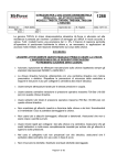
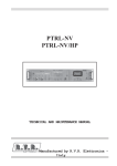
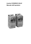
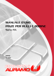
MANUALE USO E MANUTENZIONE
USE AND MAINTENANCE GUIDE
UNITA’ LINEARI
LINEAR MODULES
INDICE – INDEX
1 UNITA’ LINEARI A CINGHIA / BELT LINEAR UNITS
1
1.1 SOSTITUZIONE DELLA CINGHIA / BELT REPLACEMENT
2
1.2 SOSTITUZIONE DELLA LAMA DI COPERTURA / COVERING STRAP REPLACEMENT
3
1.3 SOSTITUZIONE DEI PATTINI GUIDA / LINEAR GUIDEWAY BLOCKS REPLACEMENT
3
1.4 SOSTITUZIONE DELLA PULEGGIA MOTRICE / DRIVE PULLEY REPLACEMENT
4
1.5 SOSTITUZIONE ALBERO MOTORIZZAZIONE / INPUT SHAFT REPLACEMENT
4
1.6 SOSTITUZIONE PULEGGIA DI RINVIO / DRIVEN PULLEY REPLACEMENT
4
1.7 LUBRIFICAZIONE PATTINI GUIDA / LUBRICATION OF LINEAR GUIDEWAY BLOCKS
4
2 UNITA’ LINEARI CINGHIA AD OMEGA / OMEGA BELT LINEAR UNITS
5
2.1 SOSTITUZIONE CINGHIA A OMEGA/ OMEGA BELT REPLACEMENT
6
2.2 SOSTITUZIONE DEI PATTINI GUIDA / LINEAR GUIDEWAY BLOCKS REPLACEMENT
6
2.3 SOSTITUZIONE DELLA PULEGGIA MOTRICE E DELLE PULEGGE CONDOTTE/
DRIVE PULLEY AND IDLE ROLLER REPLACEMENT
7
2.4 SOSTITUZIONE ALBERO MOTORIZZAZIONE / INPUT SHAFT REPLACEMENT
7
2.5 LUBRIFICAZIONE PATTINI GUIDA / LUBRICATION OF LINEAR GUIDEWAY BLOCKS
7
3 UNITA’ VITE A RICIRCOLO DI SFERE/BALLSCREW LINEAR UNITS
8
3.1 SOSTITUZIONE DELLA VITE A RICIRCOLO DI SFERE / BALLSCREW REPLACEMENT
9
3.2 SOSTITUZIONE DELLA CHIOCCIOLA/NUT REPLACEMENT
9
3.3 SOSTITUZIONE DEI PATTINI GUIDA / LINEAR GUIDEWAY BLOCKS REPLACEMENT
10
3.4 SOSTITUZIONE DELLA LAMA DI COPERTURA / COVERING STRAP REPLACEMENT
10
3.5 LUBRIFICAZIONE PATTINI GUIDA / LUBRICATION OF LINEAR GUIDEWAY BLOCKS
10
4 UNITA’ LINEARI A CREMAGLIERA/RACK & PINION LINEAR UNITS
11
4.1 SOSTITUZIONE PIGNONE-CREMAGLIERA/ RACK & PINION REPLACEMENT
12
4.2 SOSTITUZIONE ALBERO MOTORIZZAZIONE / INPUT SHAFT REPLACEMENT
12
4.3 SOSTITUZIONE DEI PATTINI GUIDA / LINEAR GUIDEWAY BLOCKS REPLACEMENT
13
4.4 SOSTITUZIONE DEI SOFFIETTI/ ELASTIC BELLOWS REPLACEMENT
13
4.5LUBRIFICAZIONE PATTINI GUIDA E PIGNONE / LUBRICATION OF LINEAR GUIDEWAY BLOCKS AND PINION
13
5 NOTE GENERALI / GENERALS REMARKS
14
UNITA’ LINEARI A CINGHIA
BELT LINEAR UNITS
1
1.1 SOSTITUZIONE DELLA CINGHIA
In caso di sostituzione della cinghia occorre seguire la procedura qui
riportata.
Smontare i tasselli di copertura (1), svitare i grani del tassello tiro lama (2),
rimuovere i deflettori (8) facendo attenzione agli OR-Ring posizionati sui
deflettori ,su entrambi i lati e rimuovere la lama di copertura (3).
Avanzare il carro (28) nella direzione della testata di rinvio. Smontare la
testata di rinvio svitando le viti di tensionamento (4) e le viti di fissaggio (5).
Rimuovere la testata (5a) e la testata di rinvio (21). Rimuovere la puleggia
(22).
Allentare le viti di fissaggio (6) della cinghia presenti tra carro e tassello
cinghia (6a) al fine di estrarre i denti della cinghia (7) in presa.
Avanzare il carro nella direzione della testa motrice. Svitare le viti (5) e
rimuovere la testata lato motorizzazione (5b) , completa di albero (16) e
puleggia (15). Allentare le viti di fissaggio (6) della cinghia presenti sul carro
al fine di estrarre la parte di cinghia (7) in presa.
Inserire la cinghia (7) tra carro e tassello cinghia incastrando i primi tre
denti della cinghia, avvitando le viti (6).Ripetere la stessa operazione
sull’altro tratto di cinghia. Per il montaggio percorrere a ritroso le istruzioni
di smontaggio
Tensionare la cinghia mediante le apposite viti di tensionamento (4),
facendo attenzione che la cinghia non si tensioni perdendo l’allineamento
con il profilo di alluminio. Quando si procede al tensionamento occorre
verificare anche la scorrevolezza del carro, verificando in particolare che sia
privo di impuntamenti. I valori di tensionamento sono funzione della taglia
della cinghia e della corsa dell’unità, qui sotto sono riportati gli intervalli di
tensionamento.
1.1 BELT REPLACEMENT
To replace the belt follow these instructions.
Remove the covering block (1), unscrew the crub screw of the strap
adjusting device (2) and remove them, remove then the carriage pads (on
both sides) taking care to the OR-Ring inside this one and then the strap
(3).
Drive the carriage in the driven station direction. Remove the driven
station unscrewing the tensioning screws (4) and the assembly screws (5).
Remove the head (5a) and the driven station (21). Remove the driven
pulley (22) then.
Loose the assembl screws (6) between the carriage and belt pad (6a) and
pull out the belt (7).
Drive the carriage in the drive station direction. Unscrew the screws (5)
and remove the drive station (5b), with the input shaft (16) and driving
pulley (15). Loose the assembly screws (6) between carriage and belt pad
and pull out the belt (7) (Drive station side).
Assemble the belt (7), fixing the first three teeth between carriage and
belt pad, screwing the screws (6). Repeat this step also on the other belt
side. For assembly follow the disassembling procedure in the opposite
sequence.
Tension the belt by tensioning adjustment screws (4), in order to have
the correct alignment between belt and aluminium profile.
Please check also carriage’s smooth motion , not to have stop-and-go
motion. Tensioning values are indicated in table below.
2
TAGLIA
SIZE
15-65
20-80
25-110
Dopo aver portato in tensione la cinghia muovere manualmente il carro
lungo tutto la corsa dell’unità in entrambe le direzioni per un numero
minimo di 10 corse al fine di far assestare la cinghia.
Effettuare la verifica del corretto tensionamento mediante tensiometro
misurando la frequenza della risposta della cinghia, seguendo questa
procedura:
•
Portare il carro in battuta verso la puleggia motrice
•
Percuotere la cinghia in prossimità del tastatore del
frequenziometro, effettuare questa operazione per tre
volte verificando la ripetibilità del valore.
•
Misurare il tratto libero della cinghia compreso tra il
carro e la puleggia folle
•
Confrontare il valore di frequenza ottenuta con i valori
nominali riportati nella tabella sottostante tenendo
conto della taglia dell’unità e della lunghezza del tratto
libero di cinghia.
LUNGHEZZA CINGHIA
BELT LENGTH
[m]
0,25
0,50
0,75
1,00
1,25
1,50
1,75
2,00
2,25
2,50
2,75
3,00
3,25
3,50
3,75
4,00
4,25
4,50
COPPIA TORQUE (Ncm)
40-80
100-200
135-270
After the tensioning operation move the carriage manually along its
whole stroke in both directions for 10 times.
Check the correct tensioning of the belt, measuring the belt frequency in
the following way:
•
•
•
•
Move the carriage in the direction of the Drive pulley
Hit the belt very next to the probe of the frequency
meter instrument, reapeat this operation 3 times,
checking the repeatability of the measurements.
Measure the free length of the belt between the
carriage and the driven pulley
Compare the measured values with the values in the
table below.
FREQUENZA/FREQUENCY
[Hz]
15-65
20-80 25-110
155
123
147
78
61
73
52
41
49
39
31
37
31
25
29
26
20
24
22
18
21
19
15
18
17
14
16
16
12
15
14
11
13
13
10
12
12
9
11
11
9
10
10
8
10
10
8
9
9
7
9
8
7
8
Riposizionare la lama di copertura e procedere al montaggio seguendo le
operazioni di smontaggio a ritroso.
Reassemble the blade following the disassembly procedure in the
opposite way.
1.2 SOSTITUZIONE DELLA LAMA DI COPERTURA
1.2 COVERING STRAP REPLACEMENT
Smontare i tasselli di copertura (1). Allentare i tasselli di tiro molla (2)
posti su entrambe le testate ed estrarre la lama di copertura (3).
Smontare i deflettori (8) posti sul carro facendo attenzione agli OR-Ring
posti all’interno dei deflettori e sfilare la lama (3).
Inserire la lama di copertura (3) facendo attenzione a non piegarla.
Assemblare i deflettori (8) sul carro e fissare la lama di copertura (3)
mediante gli appositi tasselli tiro molla (2), infine fissare i tasselli di
copertura (1).
Disassemble the covering block (1). Loose the strap adjusting device (2)
(done on both unit side) and extract the strap (3). Remove the carriage
pad (8) and take care not to loose the O-Ring inside to the carriage pad
and pull out the strap (3).
Assemble the new strap, take care not to bend it. Assemble the carriage
pad and fix the strap (3) by the strap adjusting device and then assemble
the covering block (1)
1.3 LINEAR GUIDEWAY BLOCKS REPLACEMENT
1.3 SOSTITUZIONE DEI PATTINI GUIDA
Per sostituire i due pattini (26), occorre seguire la procedura relativa allo
“SOSTITUZIONE CINGHIA” (§1.1) . Una volta smontata la cinghia si può
procedere allo smontaggio del carro facendo avanzare il carro. Durante
questa operazione montare i trattenitori sfere sui pattini (26) e sfilare il
carro (28) dalla guida (27).
Per smontare i due pattini (26) dal carro(28) bisogna svitare le viti (9) di
fissaggio tra pattino e carro, scollegare il circuito di lubrificazione. Una
volta rimossi i pattini danneggiati rimontare i nuovi pattini sul carro
facendo attenzione a non sfilare i trattenitori-sfere dei pattini, durante il
montaggio.
Posizionare il carro in modo tale da essere coincidente con il profilo della
guida sulla unità. Avanzare il carro facendo fuoriuscire i trattenitori dei
pattini. Una volta verificato il corretto posizionamento tra pattini e guida
procedere al rimontaggio della cinghia seguendo in modo a ritroso le
operazioni di smontaggio della cinghia.
To remove the blocks (26) follow the instruction of BELT REPLACEMENT
(§1.1) . After this operation it’s possible to disassemble the carriage
moving this one, before assembly the balls-holder on the blocks (26) then
pull out the carriage (28) from the rail (27).
To remove the blocks (26) from the carriage (28) unscrew the screws (9)
of fixing between carriage and block, disconnect the lubrication circuit of
the blocks. Remove the old block and assemble the new blocks on the
carriage. In this phase don’t remove the balls- holder.
Positione the carriage to have the block aligned with the rail.
Drive the carriage and blocks on the rail and remove the holder from the
blocks. After this operation, assemble the unit following the disassembly
procedure in the opposite sequence.
3
1.4 SOSTITUZIONE DELLA PULEGGIA MOTRICE
1.4 DRIVE PULLEY REPLACEMENT
Per questa operazione occorre seguire le istruzioni relative allo
SOSTITUZIONE DELLA CINGHIA (§1.1) .
Smontare la flangia della motorizzazione (10) svitando le viti (11), sfilare
la flangia completa dell’alberino,della puleggia e dei cuscinetti. Rimuovere
il seeger (12), il cuscinetto (13),il seeger (12a), il calettatore (14) ed infine
la puleggia(15).
Montare la nuova puleggia (15) sull’albero (16) procedere al montaggio
del calettatore chiudendo il calettatore con una coppia di 10 Nm, poi
procedere al montaggio del seeger (12a), del cuscinetto (13) e del seeger
(12).
La puleggia motrice deve essere montata seguendo a ritroso la procedura
di smontaggio della puleggia motrice e della cinghia.
To remove the drive pulley follow the BELT REPLACEMENT instruction
(§1.1) .
Remove the flange (10) unscrewing the screws (11), pull out the
flange,the input shaft with the drive pulley and the bearings. Remove the
seeger (12), bearing (13), the seeger (12a), the shrink disk (14) and the
drive pulley (15).
Assemble the new drive pulley (15) on the shaft (16), locking the shrink
disk according to table at page 14 , and then assemble the seeger (12
a),the bearing (13) and the seeger (12).
The drive pulley must be assembled following the disassembling prcedure
in the opposite sequence.
1.5 INPUT SHAFT REPLACEMENT
1.5 SOSTITUZIONE ALBERO MOTORIZZAZIONE
Procedere come descritto nella operazione “Sostituzione della Puleggia
Motrice” (§1.4) . Una volta smontata la puleggia motrice procedere allo
smontaggio dell’anello di tenuta (20), del seeger (19), del cuscinetto (18) e
del distanziale (17). Procedere alla sostituzione dell’alberino. Per il
montaggio seguire a ritroso la procedura di smontaggio dell’albero e
della puleggia motrice.
N.B. La coppia di serraggio del calettatore deve essere di 10 Nm.
1.6 SOSTITUZIONE PULEGGIA DI RINVIO
Come prima operazione seguire la procedura della “Sostituzione della
cinghia” (§1.1) smontando la sola testata di rinvio. Procedere con la
rimozione del gruppo composto da puleggia di rinvio (22), alberino (25) e
cuscinetti (24).
Smontare i seeger (23) e (23 a), smontare i cuscinetti (24), sfilare la
puleggia (22) dall’albero (25). Sostituire l’albero (25) e rimontarlo
seguendo in modo a ritroso la procedura di smontaggio della puleggia di
rinvio.
1.7 LUBRIFICAZIONE PATTINI GUIDA
La lubrificazione dei pattini guida è di tipo manuale e deve essere
effettuata ogni 100 Km.
L’operazione di ingrassaggio della guida deve essere effettuata
introducendo il grasso di lubrificazione attraverso l’ingrassatore conico a
pressione presente sul deflettore ed identificabile con il simbolo del
triangolo, come indicato nella figura sottostante.
Follow the Drive Pulley Replacement instruction. Then disassemble the
seal (20) ,the seeger (19), the bearing (18) and the spacer (17). replace the
input shaft. Assemble the input shaft following the dissasembling
instruction in opposite sequence.
The tightening torque of the shrink disk must be according to table at
page 14.
1.6 DRIVEN PULLEY REPLACEMENT
Follow the Belt Replacement Instruction (§1.1) removing the driven
station .
Remove teh assembly composed by driven pulley (22), shaft (25) and
bearing (24).
Disassemble the seeger (23) and (23 a), the bearings (24) pull out the
pulley (22) from the shaft (25). replace the shaft (25). Assemble following
in the backward sequence the disassembling driven pulley instruction.
1.7LUBRICATION OF BALLS RECIRCULATING BLOCKS
The lubrication of the linear guideway blocks is manually done every 100
Km.
The lubrication operation of the linear guideway must be done
introducing the grease through the input lubrication point on the carriage
pad with a triangol symbol as shown in the picture below.
Il tipo di grasso è il MOBILGREASE SPECIAL NLGI-2 ISO VG150, la quantità
di grasso da introdurre ad ogni ciclo di lubrificazione è pari a:
• 15-65:
• 20-80:
• 25-110:
25 gr
35 gr;
45 gr;
The grease type is MOBILGREASE SPECIAL NLGI-2 ISO VG150, the quantity
is:
•15-65:
• 20-80:
• 25-110:
25 gr
35 gr;
45 gr;
4
UNITA’ LINEARI CINGHIA AD OMEGA
OMEGA BELT LINEAR UNITS
5
2.1 SOSTITUZIONE CINGHIA A OMEGA
2.1 OMEGA BELT REPLACEMENT
Per effettuare la sostituzione della cinghia ad Omega occorre avanzare il carro
verso la testata (5). Svitare le viti di tensionamento (1) e di fissaggio (2) poste
sul tassello di copertura (3) della cinghia e procedere alla rimozione di questo.
Svitare le viti di fissaggio (4) della testata (5) e rimuovere la testata.
Svitare le viti (6) del tassello del tiro cinghia (7), rimuovere il tassello
superiore (7) e inferiore (7a).
Avanzare il carro verso la testata(12). Svitare le viti (8), (9) e rimuovere il
tassello di copertura della cinghia (11); svitare le viti (10) e rimuovere la
testata (12).
Rimuovere la piastra (13) svitando le viti (14), successivamente svitare le viti
(15) e rimuovere le due testate laterali (16). Estrarre la cinghia dentata (17).
Per il montaggio seguire le istruzioni dello smontaggio in modo a ritroso.
To replace the Omega belt move the carriage in the diretion of the head (5).
Unscrew the tensioning screws (1) and the assembly screws (2) on the
covering strap (3) and remove it.
Unscrew the assembly screws (4) of the head block (5) and remove it.
Unscrew the screws (6) of the belt adjusting device(7), remove this one and
the lower block (7a).
Drive the carriage in the direction of the head (12). Unscrew the screws (8),
(9) and remove the covering system of the belt (11); then unscrew the
screws (10 )and remove the head block (12).
Remove the plate (13) unscrewing the screws (14), then unscrew the screws
(15) and remove both lateral head (16). Pull out the belt (17).
To reassemble the belt follow the disassembling instruction in a backward
sequence.
2.2 SOSTITUZIONE DEI PATTINI GUIDA
Per effettuare la sostituzione di entrambi i pattini guida (18) occorre seguire
la procedura prevista per la sostituzione della cinghia (§2.1) , infatti basta
provvedere allo smontaggio dei tasselli di copertura cinghia (3) e (11) e delle
relative testate (5) e (12).
Una volta effettuata questa procedura, far avanzare il carro fino a sfilare
entrambi i pattini (18),durante questa operazione bisogna montare i
trattenitori sfere dei pattini. Sfilato il carro, scollegare il circuito di
lubrificazione dei pattini, successivamente svitare le viti di fissaggio (18 a) dei
pattini sul carro.
Montare i pattini sul carro fissandoli mediante le apposite viti di fissaggio,
fissare i raccordi di lubrificazione ai nuovi pattini e procedere al montaggio del
carro seguendo in modo ritroso le istruzioni di smontaggio.
2.2 LINEAR GUIDEWAY BLOCKS REPLACEMENT
To remove the blocks (18) follow the instruction of BELT REPLACEMENT,
disassembly the covering strap (3) e (11) and the head blocks (5) e (12).
Drive the carriage to remove the blocks (18),during this phase assemble the
balls-holder of the blocks. When the carriage is pulled out disconnect the
blocks lubrication circuit. Then unscrew the assembly screws (18 a) for
carriage and blocks.
assemble the blocks on the carriage by the screws, re-connect the
lubrication circuit and follow the disassembling instruction in a backward
sequence.
6
2.3 SOSTITUZIONE DELLA PULEGGIA MOTRICE E DELLE
PULEGGE CONDOTTE
Per effettuare la sostituzione della puleggia motrice (22) occorre eseguire la
procedura di sostituzione della cinghia (§2.1) .
Svitare le viti (20) poste sulla piastra lato-motorizzazione (21), rimuovere
l’intero gruppo della motorizzazione, procedendo allo smontaggio del seeger
(24 a), del cuscinetto (24), del seeger (24b), del calettatore (23) . Sostituire la
puleggia motrice (22) e rimontare il tutto percorrendo a ritroso la procedura di
smontaggio della puleggia motrice e della cinghia omega.
N.B. È importante montare il calettatore (23) serrandolo alla coppia di chiusura
di 10 Nm.
Per la sostituzione di una o entrambe le pulegge condotte occorre seguire per
intero la procedura relativa alla puleggia motrice e inoltre provvedere allo
smontaggio delle piastre (31) (lato motorizzazione e lato opposto alla
motorizzazione) svitando le viti (30) e (32).
Provvedere alla rimozione degli alberi condotti, rimuovere la puleggia condotta
(28) danneggiata, mediante lo smontaggio del seeger (29a) e del cuscinetto (29).
Sostituita la puleggia condotta procedere al montaggio seguendo a ritroso la
procedura di smontaggio.
2.4 SOSTITUZIONE ALBERO MOTORIZZAZIONE
Per la sostituzione dell’albero della motorizzazione si deve seguire la procedura
indicata per la sostituzione della puleggia motrice (§2.3). Inoltre si deve
procedere allo smontaggio del cuscinetto (25), mediante lo smontaggio del
seeger (25 a) e del distanziale. Sostituire l’albero di motorizzazione e
assemblare seguendo in modo a ritroso le istruzioni di sostituzione dell’albero
motorizzazione
2.5 LUBRIFICAZIONE PATTINI GUIDA
La lubrificazione dei pattini guida è di tipo manuale e deve essere effettuata
ogni 100 Km.
L’operazione di ingrassaggio della guida deve essere effettuata introducendo il
grasso di lubrificazione attraverso i punti di lubrificazione indicati qui sotto nella
figura
Il tipo di grasso è il MOBILGREASE SPECIAL NLGI-2 ISO VG150, la quantità di
grasso da introdurre ad ogni ciclo di lubrificazione è pari a:
•15-65:
• 20-80:
• 25-110:
2.3 DRIVE PULLEY AND IDLE ROLLER REPLACEMENT
To remove the driving pulley (22) follow the BELT REPLACEMENT
instruction.
Unscrew the screws (20) of the flange (21) (motorization side), remove
the motorization group, remove the seeger (24 a), the bearing (24), the
shrink disk (23) and the seeger (24 b). Replace the driving pulley (22) and
reassemble following in a backward sequence the drive pulley and belt
replacement instruction.
The tightening torque of the shrink disc must be according to table at
page 14.
To replace one or both idle roller follow the previous procedure and then
disassemble plate (31) (motorization side) unscrewing the screws (30)
and (32).
Remove the shaft of the idle roller, remove the idle roller removing
before the seeger (29a ) and the bearing (29).
assemble the new idle roller and assemble following in backward
sequence the instruction of disassembling.
2.4 INPUT SHAFT REPLACEMENT
To replace the input shaft follow the instruction about the driving pulley
replacement (§2.3) . Then disassemble the bearing (25), disassembling
before the seeger (25 a) and the spacer. replace the input shaft and
reassemble it following in a backward sequence the input shaft
replacement instruction.
2.5 LUBRICATION OF LINEAR GUIDEWAY BLOCKS
The lubrication of linear guideway blocks is manual and should be done
every 100 Km.
The lubrication operation of the rail must be done introducing the grease
through the input lubrication point on the carriage’s pad, identified by a
triangol symbol as shown in the picture below.
The grease type is MOBILGREASE SPECIAL NLGI-2 ISO VG150, the quantity
is:
•15-65:
• 20-80:
• 25-110:
25 gr
35 gr
45 gr
25 gr
35 gr
45 gr
7
UNITA’ VITE A RICIRCOLO DI SFERE
BALLSCREW LINEAR UNITS
8
3.1 SOSTITUZIONE DELLA VITE A RICIRCOLO DI SFERE
3.1 BALLSCREW REPLACEMENT
Per sostituire la vite a ricircolo, occorre svitare le viti di fissaggio del
tassello della lama di copertura(1), svitare i grani del tassello tira lama (2),
rimuovere i deflettori (10) facendo agli O-Ring posizionati nei deflettori,
sfilare la lama (12)
Svitare le viti di fissaggio (3) della flangia (4) e rimuoverla, svitare le viti di
fissaggio (5), svitare la ghiera di bloccaggio (6). Rimuovere la testata lato
motorizzazione (8) completa del cuscinetto (7).
Procedere alla rimozione della testata (7a) sul lato opposto alla
motorizzazione svitando le viti di fissaggio (5).
Per sostituire la vite, occorre utilizzare il trattenitore-sfere della chiocciola
al fine di evitare lo sfilamento delle sfere.
Avanzare il carro (11), durante questa operazione montare i trattenitori
sfere per i pattini (17) e sfilare il carro (11). Calettare sulla vite(16) il
trattenitore sfere della chiocciola ruotare la vite (16) accompagnando il
trattenitore nella chiocciola, una volta rimossa la vite assicurarsi che il
trattenitore sia ben fissato nella chiocciola.
Montare la nuova vite avendo l’accortezza di non far scappare il
trattenitore fino al corretto accoppiamento tra la vite (16) e la chiocciola
(14).
Procedere al rimontaggio delle testate e della lama di copertura seguendo
la procedura di smontaggio in modo a ritroso.
To remove the ballscrew unscrew the clamping screws of the covering
strap (1) and then unscrew the screws of the strap adjusting device (2),
remove the carriage pad (10), taking care to the O-Ring located inside
them, pull out the strap (12).
To remove the flange (4) unscrew the clamping screws (3), unscrew the
screws (5), unscrew the self-locking nut (6). Remove the drive station (8)
with the bearing (7). Remove the driven station (7a) unscrewing the
screws (5).
To replace the ballscrew use the plastic nut-holder, to avoid the balls fall.
Drive the carriage (11), during this phase assemble the balls-holder of the
blocks (17) and pull out the carriage (11).
assemble on the ballscrew (16) the plastic nut-holder, turn the ballscrew
(16) driving the nut-holder into the nut (14) and then remove the screw
(16).
Assemble the ballscrew, taking care not to scare away the nut-holder until
to correct assembly of the nut (14) on the screw (16).
assemble both heads and the covering strap following the disassembly
procedure in the opposite sequence.
3.2 SOSTITUZIONE DELLA CHIOCCIOLA
Per sostituire la chiocciola seguire la procedura illustrata nella procedura
“Sostituzione della Vite a Ricircolo di Sfere” (§3.1) .
Una volta sfilato il carro e rimossa la vite,procedere alla rimozione della
chiocciola (14). Per rimuovere la chiocciola (14) svitare le viti di fissaggio
(15) del supporto chiocciola (16). Una volta smontato il supporto
chiocciola (14), svitare le viti di fissaggio (13) e rimuovere la chiocciola
(14).
Sostituire la chiocciola (14) e rimontarla lasciando il trattenitore al suo
interno.
Montare la chiocciola nel supporto seguendo in modo a ritroso la
procedura di smontaggio, fissare il supporto chiocciola (15) al carro (11), a
questo punto montare la vite (16) nella chiocciola (14). Accompagnare
durante la rotazione della vite (16) il trattenitore della chiocciola fino al
corretto montaggio vite-chiocciola.
3.2 NUT REPLACEMENT
To replace nut follow the procedure about Ballscrew Replacement (§3.1) .
Pull out the carriage and the screw is removed, remove then the nut (14).
To remove the nut (14) unscrew the screws (15) of the nut support (16).
When the nut support (16) is disassembled unscrew the fixing screw (13)
and remove the nut (14).
Replace the nut with the balls-holder in it.
assemble the nut into the support following in backwards sequence the
disassembling procedure, screw the nut support on the carriage and
assemble the ballscrew into the nut. During this assembly step assemble
the screw (16) into the nut (14). Drive the nut holder during the ballscrew
rotation until to the right match between nut (14) and ballscrew (16) is
done, then after this operation remove the nut-holder.
Assemble the carriage with its ballscrew into the unit and then assemble
following in the backwards sequence the disassembling instruction.
9
Montare il gruppo composto da carro più vite-chiocciola sull’unità e
procedere al montaggio delle parti seguendo le istruzioni di smontaggio
in modo a ritroso .
3.3 SOSTITUZIONE DEI PATTINI GUIDA
Per procedere alla sostituzione dei pattini occorre seguire le istruzioni
relative alla Sostituzione della Vite a Ricircolo di sfere (§3.1)
Avanzare il carro (11) fino a sfilare completamente l’intero carro dal
profilo in alluminio (22), durante questa operazione montare i trattenitori
sfere sui pattini (17). Svitare le viti fissaggio (21) dei pattini sul carro,
scollegare i circuiti di lubrificazione dai pattini. Sostituire i pattini con
quelli nuovi, fissare i pattini sul carro mediante le viti di fissaggio.
Procedere al rimontaggio percorrendo a ritroso la procedura di
smontaggio seguita prima.
3.4 SOSTITUZIONE DELLA LAMA DI COPERTURA
Svitare le viti di fissaggio dei tasselli di copertura (1), allentare i grani dei
tasselli tiro lama (2). Svitare le viti di fissaggio dei deflettori (10), sfilare i
due deflettori avendo cura degli O-Ring posizionati nei deflettori.
Sfilare la lama di copertura (12) dal carro (11). Inserire la nuova lama di
copertura (12) nel carro (11), procedere al montaggio seguendo in modo
a ritroso le istruzioni di smontaggio
3.5 LUBRIFICAZIONE PATTINI GUIDA
L’operazione di ingrassaggio della guida deve essere effettuata
introducendo il grasso di lubrificazione attraverso l’ingrassatore conico a
pressione presente sul deflettore ed identificabile con il simbolo del
triangolo, come indicato nella figura sottostante.
La lubrificazione dei pattini guida è di tipo manuale e deve essere
effettuata ogni 100 Km.
La lubrificazione della vite deve essere effettuata ogni 500 ore.
L’operazione di ingrassaggio della guida deve essere effettuata
introducendo il grasso attraverso l’ingrassatore conico a pressione
presente sul deflettore ed identificabile con il simbolo del triangolo,
mentre per la vite è identificato dal simbolo di un quadrato, come
mostrato nella figura qui sotto.
3.3 LINEAR GUIDEWAY BLOCKS REPLACEMENT
To replace the blocks follow the Ballscrew Replacement
instruction (§3.1)
Drive the carriage (11) and to pull it out of the aluminium profile
(22), during this phase mount the ball-holder on the blocks.
Unscrew the clamping screw (21), disconnect the lubrication
system from the blocks. Replace the blocks, assemble the new
blocks on the carriage by the clamping screws.
Reassemble following the disassembling instruction in the
backward sequence.
3.4 COVERING STRAP REPLACEMENT
Unscrew the clamping screws of the covering strap (1), loose the
screws of the strap adjusting device (2). Unscrew the clamping
screws of the carriage pads (10), remove the carriage pads,
taking care to the O-Ring located inside the carriage pads. Pull
out the blade (12) from the carriage (11).
Mount the new blade (12) into the carriage (11), follow the
disassembling instruction in the backward the sequence.
3.5 LUBRICATION OF LINEAR GUIDEWAY BLOCKS
The lubrication of linear guideway blocks is manually every 100
Km.
The lubrication of the ballscrew must be done every 500 hours.
The lubrication operation of the rail must be done introducing
the grease through the input lubrication point on the carriage
pad, identified by a triangol symbol, while for the ballscrew by a
square symbol, as shown in the picture below.
The grease type is MOBILGREASE SPECIAL NLGI-2 ISO VG150, the
quantity for the blocks is:
•15-65:
• 20-80:
• 25-110:
25 gr
35 gr
45 gr
Il tipo di grasso è il MOBILGREASE SPECIAL NLGI-2 ISO VG150, la quantità
di grasso da introdurre per i pattini ad ogni ciclo di lubrificazione è pari a:
The grease to use for the ballscrew is the MOBILGREASE
SPECIAL NLGI-2 ISO VG15, the quantity to introduce is:
•15-65: 25 gr
• 20-80: 35 gr
• 25-110: 45 gr
•15-65:
• 20-80:
• 25-110:
30 gr
40 gr
50 gr
Il tipo di grasso da utilizzare per la vite è sempre il MOBILGREASE SPECIAL
NLGI-2 ISO VG150 , in questo caso la quantità da introdurre ad ogni ciclo
di lubrificazione è pari a:
•15-65: 30 gr
• 20-80: 40 gr
• 25-110: 50 gr
10
UNITA’ LINEARI A CREMAGLIERA
RACK & PINION LINEAR UNITS
11
4.1 SOSTITUZIONE PIGNONE-CREMAGLIERA
4.1 RACK AND PINION REPLACEMENT
Per sostituire il sistema pignone – cremagliera, svitare le viti di fissaggio
(1), rimuovere la testata (2), prestando attenzione al soffietto (3). Svitare
le viti di fissaggio tra il soffietto (3) e la testata (2) e il tra soffietto e il
carro (7). Ripetere la stessa procedura sulla testata (5) svitando le viti (4)
e rimuovere il soffietto (6) seguendo la stessa procedura adottata per il
soffietto (3).
Far avanzare il carro (7) in una delle due direzioni, raggiunta l’estremità
della guida (17) con il pattino (16) calzare il trattenitore sfere sul pattino
facendo avanzare il carro, ripetere questa operazione anche sul secondo
pattino.
Una volta sfilato il carro procedere allo smontaggio del pignone (9)
smontando il calettatore (8) .
Smontare la cremagliera (9a) svitando le viti di fissaggio tra questa e il
profilo in alluminio (18).
Procedere alla sostituzione del pignone e della cremagliera con quella di
ricambio.
A questo punto procedere al rimontaggio delle parti, seguendo in modo a
ritroso la procedura di smontaggio prima descritta.
To replace the rack and pinion, unscrew the clamping screws (1) and
remove the head (2), take care to the elastic bellows (3). Unscrew the
clamping screws between elastic bellows (3) and head (2) and between
elastic bellow (3) and carriage (7). Repeat the same procedure on the
other head (5) unscrewing the screws (4) and remove the elastic bellow
(6) in the same way done for the elastic bellow (3).
Drive the carriage (7) until the block (16) is at the end of the rail (17), then
assemble on the first block the holder, drive then the carriage in order to
assemble the second holder on the second block.
when the carriage disassembled disassemble the pinion (9) unscrewing
the shrink disk (8).
Disassemble the rack (9a) unscrewing the clamping screw between rack
and aluminium profile (18). replace the pinion and rack .
reassemble the parts, following in the backward sequence the
disassembling procedure.
4.2 SOSTITUZIONE ALBERO MOTORIZZAZIONE
Per la sostituzione dell’albero della motorizzazione (13) seguire la
procedura utilizzata per la Sostituzione Pignone-Cremagliera (§4.1).
Svitare le viti (10) e (12) di fissaggio del mandrino (11), rimuovere il
mandrino. Sfilare l’albero della motorizzazione (13), rimuovere il seeger
(15) e poi rimuovere il cuscinetto (14)
Per il montaggio seguire la procedura dello smontaggio in modo a ritroso.
4.2 DRIVE SHAFT REPLACEMENT
To replace the drive shaft follow the procedure of Rack and Pinion
replacement (§4.1). Unscrew the fixing screws (10) e (12) of the chuck
(11) and remove it. Pull out the drive shaft(13), remove the seeger (15)
and bearing (14) and replace the shaft.
reassemble following the disassembly instruction in a backward
sequence.
12
4.3 SOSTITUZIONE PATTINI GUIDA
4.3 LINEAR GUIDEWAY BLOCKS REPLACEMENT
Per sostituire i pattini (16) seguire la procedura per lo smontaggio del
sistema pignone-cremagliera (§4.1) .
Estrarre il carro dal profilo, durante questa operazione montare i
trattenitori sfere dei pattini (16). Successivamente svitare le viti (19)
rimuovere i pattini (16) e scollegare i circuiti di lubrificazione. Montare i
pattini (16) fissandoli al carro (7) mediante le viti (19).
Procedere al rimontaggio del carro, seguendo in modo a ritroso la
procedura per la sostituzione dei pattini.
To replace the blocks (16) follow the instruction about the Rack & Pinion
Replacement.
Pull out the carriage (7), during this operation assemble on the blocks the
ball-holder. Then unscrew the screws (19) remove the blocks and
disconnect the lubrication circuit. screw the blocks on the carriage by their
screws (19).
Mount the parts following in the backward sequence the disassembling
instruction.
4.4 SOSTITUZIONE DEI SOFFIETTI
4.5 ELASTIC BELLOWS REPLACEMENT
Per sostituire il sofffietto seguire le istruzioni per la sostituzione PignoneCremagliera (§4.1). Una volta sfilato il carro svitare le viti tra il carro (7) ed
il soffietto (3). Procedere alla sostituzione ed al rimontaggio del soffietto (3)
seguendo in modo a ritroso le istruzioni di smontaggio. Analoga procedura
deve essere seguita per il soffietto (6).
Follow the instruction about the Rack and Pinion Replacement (§4.1). Pull
out the carriage (7) unscrew the screws between carriage (7) and elastic
bellow (3). Replace the elastic bellow (3) following in a backward sequence
the disassembly instruction. Follow the same procedure for the elastic
bellow (6).
4.6 LUBRIFICAZIONE PATTINI GUIDA E PIGNONE
4.6 LUBRICATION OF LINEAR GUIDEWAY BLOCKS AND
PINION
La lubrificazione dei pattini guida e del pignone-cremagliera è di tipo
manuale e deve essere effettuata ogni 100 Km.
L’operazione di ingrassaggio deve essere effettuata introducendo il grasso
di lubrificazione attraverso l’ingrassatore conico a pressione presente sul
tassello di collegamento col soffietto, come indicato nella figura
sottostante.
Il tipo di grasso è il MOBILGREASE SPECIAL NLGI-2 ISO VG150, la quantità di
grasso da introdurre, valida sia per i pattini che per il pignone-cremagliera,
ad ogni ciclo di lubrificazione è pari a:
•15-65: 25 gr
• 20-80: 35 gr
• 25-110: 45 gr
The lubrication of balls recirculating blocks is manually done every 100 Km.
The lubrication operation of the rail must be done introducing the grease
through the lubrication point as shown in the picture below.
The grease type is MOBILGREASE SPECIAL NLGI-2 ISO VG150, the quantity to
introduce, for the blocks and pinion, is:
•15-65:
• 20-80:
• 25-110:
25 gr
35 gr
45 gr
13
5 NOTE GENERALI
5 GENERALS NOTES
CONTROLLI PRECAUZIONALI ALL’AVVIO
CHECKS BEFORE OPERATING THE UNITS
Accertarsi che la struttura su cui viene montata l’unità sia in grado di
sopportare il carico massimo previsto senza subire deformazioni che
comprometterebbero il funzionamento dell’intero sistema.
È indispensabile al fine di salvaguardare la durata dell’unità lineare evitare
qualsiasi forma di urto/vibrazione.
Evitare di superare i carichi nominale massimi ammissibili propri delle
unità per evitare gravi danni al sistema, durate fortemente ridotte e
deformazioni permanenti che pregiudicherebbero la funzionalità del
sistema.
Nel caso in cui la traslazione sia su un asse verticale è consigliabile
prevedere un sistema frenante che mantenga fermo il carico nel caso in
cui il motore sia spento.
Ensure that the structure the unit is assembled on is strong enough to
stand the maximum load without having any deformation that could
affect the proper operation of the unit.
In order to have the statistical lifetime of the unit it’s important to avoid
any impact and vibration.
Never exceed the max nominal load capacities of the units in order to
avoid serious damage to the system, strongly reduced life time and
permanent deformations that could compromise the proper operation of
the system.
When the unit is used in application in which the load is moved along the
vertical axis it’s necessary to provide the unit with a brake that stops the
load when the motor is off.
COPPIA DI SERRAGGIO DEI CALETTATORI
SHRINK DISKS TIGHTENING TORQUE
COPPIA DI SERRAGGIO DEI GIUNTI
COUPLINGS TIGHTENING TORQUE
TIPO
TYPE
D1[mm]
D2 [mm]
COPPIA DI SERRAGGIO
TIGHTENING TORQUE
[Nm]
EK2-20
8-25
8-25
8
EK2-60
12-32
12-32
15
EK2-150
19-36
19-36
35
EK2-300
20-45
20-45
70
14
CLASSI DI SERRAGGIO
TIGHTENING CLASS
15
Cop ISOMOVE Manuale 2011:Cop ISOMOVE Manuale 19/10/11 11.30 Page 1
TORINO
Direzione Generale e Stabilimento di Produzione - Headquarter and Production Plant
Via Mappano, 17 - 10071 Borgaro T.se (TO)
T +39 011 451 8611 (centr. r.a.) - F +39 011 470 4891
[email protected]
MILANO
Via Meccanica, 5
20026 Novate (MI) - Z. I. Vialba
T +39 02 356 0990 - 382 01 590 (r.a.)
F +39 02 356 0943
[email protected]
ISTRUZIONI_ULS_ITA/ENG_REV00
ISTRUZIONI_ISOMOVE ITA/ENG REV02
07/2008
PADOVA
Via Secchi, 81
35136 Padova
T +39 049 872 5983
F +39 049 856 0965
[email protected]
BOLOGNA
Via Del Lavoro, 6/A
40051 Altedo (BO)
T +39 051 871 949 (3 linee r.a.)
F +39 051 870 329
[email protected]
FIRENZE
Via Galileo Galilei, 3
50015 Bagno a Ripoli - Grassina (FI)
T +39 055 643 261
F +39 055 646 6614
[email protected]
www.setec-group.com
www.setec-group.it