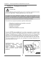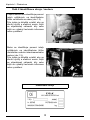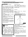
1
It's an Emak S.p.A. trademark Member of the Yama Group
42011 Bagnolo in Piano (RE) Italy
Tel. +39 0522 956611 - Fax +39 0522 951555
[email protected] - www.mybertolini.com
TRINCIASARMENTI
TONDOBROYEUSE
SCHLEGLMAHER
FLAIR MOWER
TRITURADORA DE BARRAS
KOSIARKA BIJAKOWA
MULČOVAČ
PŇOVÁ FRÉZA
BTS 65
BTS 80
ATTENZIONE! - Questo manuale deve accompagnare la macchina durante tutta la sua vita.
ATTENTION! - Le manuel doit accompagner la machine pour toute sa vie.
ACHTUNG! - Dieses Anweisungsheft muß das Gerät während seiner gesamten Lebensdauer begleiten.
WARNING! - This owner’s manual must stay with the machine for all its life.
¡ATENCION! - Este manual debe acompañar a la máquina durante toda su vida útil.
UWAGA! - Niniejsza instrukcja powinna towarzyszyc urzadzeniu przez caly okres jego eksploatacji.
UPOZORNĚNI! - Tento navod by měl byt uchovavan spolu s přistrojem po celou dobu jeho životnosti.
UPOZORNENIE! - Tento navod musi sprevadzať pristroj po celu dobu jeho životnosti
F1520306C rev.1 - Apr/2012
I
USO E MANUTENZIONE
1
1
USO E MANUTENZIONE
INDICE
Capitolo 1
Sez.1
Sez.2
Sez.3
: Premessa ............................................................... 3
Introduzione e sicurezza ............................................................ 3
Identificazione della macchina / motore ..................................... 5
Garanzia .................................................................................... 6
Capitolo 2 : Norme generali e dispositivi di sicurezza .......... 8
Sez.1
Parole, simboli e decalcomanie di allarme e sicurezza ............. 8
Sez.2
Precauzioni per lavorare in sicurezza ........................................ 9
Sez.3
Operazioni a rischio ................................................................. 12
Capitolo 3 : Dati e caratteristiche tecniche ........................... 13
Sez.1
Pesi e misure d’ingombro ....................................................... 13
Sez.2
Motore ..................................................................................... 14
Sez.3
Informazioni generali ............................................................... 15
Capitolo 4 : Comandi e strumenti di controllo ..................... 16
Sez.1
Descrizione dei comandi ......................................................... 16
Sez.2
Leve regolazioni in altezza e laterale del manubrio ................. 18
Capitolo 5 : Utilizzazione ........................................................ 19
Sez.1
Avviamento / arresto motore ................................................... 19
Sez.2
Leva frizione avanzamento macchina e movimento lame ...... 21
Sez.3
Leva selettore marce e Leve sbloccaggio ruote DX/SX .......... 22
Sez.4
Leva regolazione altezza taglio................................................ 23
Capitolo 6 : Manutenzione e regolazioni ............................... 24
Sez.1
Rifornimento della macchina ................................................... 24
Sez.2
Manutenzione periodica e straordinaria .................................. 25
2
Capitolo 1 : Premessa
Sez.1
Introduzione e sicurezza
ATTENZIONE :
Prima
dell’uso
della macchina, leggere
attentamente
questo
manuale ed il libretto
allegato sulle Norme generali per la
vostra sicurezza e conservateli per
future consulatazioni.
Scopo di questa pubblicazione è quello
di consentire al proprietario e all'operatore di utilizzare la falciatrice a flagelli
in completa sicurezza ottendo le sue
migliori prestazioni.
La consegna del prodotto da parte
del Rivenditore / Concessionario consente inoltre di assicurarsi che queste
istruzioni sull'uso e sulla manutenzione siano comprese correttamente.
Tuttavia se non comprendete parti di
questo libretto non esitate a consultare il vostro Concessionario, in quanto
è importante che tali istruzioni siano
capite e rispettate. Si raccomanda di
effettuare abitualmente la manutenzione quotidiana e di tenere un registro
in cui annotare le ore di servizio della
macchina.
Quando si necessitano parti di ricambio, è importante utilizzare solamente
ricambi originali. I Rivenditori Autorizzati forniscono i ricambi originali e possono dare consigli sul loro montaggio
e il loro uso. Il montaggio di parti di
ricambio di qualità inferiore può essere causa di danni estesi. Si consiglia
quindi la clientela di acquistare i ricambi necessari esclusivamente da un Rivenditore Autorizzato.
Fig. 1.1
A causa della notevole diversità delle
condizioni d'impiego, è impossibile alla
società fornire pubblicazioni perfettamente aggiornate e complete relative alle prestazioni o ai metodi d'uso
delle macchine di sua fabbricazione
e quindi assumersi responsabilità per
perdite o danni che possano derivare
da quanto pubblicato o da qualsiasi
errore od omissione. Nel caso in cui il
mezzo debba essere usato in condizioni anomale particolarmente gravose (per es. acqua alta o terreni molto
fangosi), vi consigliamo di consultare il
vostro Rivenditore per avere istruzioni
specifiche, per evitare di invalidare la
garanzia.
Il Costruttore della falciatrice a flagelli
non accetterà nessuna responsabilità per eventuali danni o lesioni dovuti
all'uso improprio della macchina, i cui
rischi saranno esclusivamente a carico
dell'utilizzatore.
Fanno sostanzialmente parte dell'impiego previsto anche la conformità e
il rigoroso rispetto delle condizioni di
utilizzo, assistenza e riparazione specificate dal Costruttore.
3
Capitolo 1 : Premessa
Sez.1
Introduzione e sicurezza
Per l'utilizzo, l'assistenza e la riparazione di questa falciatrice a flagelli è
necessario conoscere perfettamente
tutte le sue caratteristiche specifiche
ed essere esattamente informati delle
relative norme di sicurezza (prevenzione degli infortuni).
Si raccomanda ai clienti di rivolgersi ad
un Rivenditore Ufficiale per qualsiasi
problema d'assistenza o di registrazione che dovesse presentarsi.
Dato che la sicurezza dell'operatore
rappresenta una delle principali preoccupazioni di chi progetta e sviluppa un
nuovo motocoltivatore, i progettisti cercano di prevedere il maggiore numero possibile di dispositivi di sicurezza.
Ciò nonostante ogni anno si verificano
molti incidenti che potevano essere
evitati se l'operatore fosse stato meno
precipitoso e più cauto nel maneggiare macchinari e attrezzature agricole.
Leggere e seguire attentamente le
istruzioni di sicurezza riportate in dettaglio in questo capitolo del manuale.
Se non indicato diversamente i dati e
le informazioni contenuti in questo manuale sono applicabili a tutti i modelli.
Il contenuto di questo manuale è conforme alle ultime informazioni tecniche
disponibili al momento della stampa.
La Ditta Costruttrice si riserva il diritto
di effettuare modifiche in qualsiasi momento, senza preavviso e senza incorrere in nessuna sanzione.
Con ogni falciatrice a flagelli, oltre al
presente libretto d’istruzioni, viene consegnata anche una copia del manuale
d’uso e manutenzione del motore, che
costituisce parte integrante della docu-
mentazione a corredo.
Tutti i diritti riservati. Questo manuale
non può essere riprodotto o copiato,
per intero o in parte, senza il permesso
scritto della Emak.
4
Capitolo 1 : Premessa
Sez.2
Identificazione della macchina / motore
La falciatrice a flagelli viene identificata
attraverso i dati impressi nell’apposita
targhetta di identificazione posta sulla
base del telaio (Fig. 1.2).
E’ importante segnare tali dati, allo
scopo di assicurare un servizio pronto
ed efficiente, quando si ordinano parti
di ricambio o quando si richiedono informazioni o delucidazioni tecniche.
Fig. 1.2
Il motore viene identificato attraverso i
dati impressi nell’apposita targhetta di
identificazione posta sulla parte laterale del motore stesso (Fig. 1.3).
E’ importante segnare tali dati, allo
scopo di assicurare un servizio pronto
ed efficiente, quando si ordinano parti
di ricambio o quando si richiedono informazioni o delucidazioni tecniche.
Fig. 1.3
Identificazione della macchina
5
Capitolo 1 : Premessa
Sez.3
Garanzia
I prodotti Emak sono coperti da una garanzia che, a determinate condizioni,
copre i difetti di materiale o di costruzione. Questo libretto è pubblicato per
essere diffuso in tutto il mondo, quindi
è impossibile descrivere in dettaglio e
con esattezza i termini e le condizioni della garanzia relativi alla vendita al
dettaglio in ogni singolo Paese. Gli acquirenti di nuovi motocoltivatori sono
pregati di chiedere tutti i dettagli al Rivenditore presso il quale hanno acquistato il motocoltivatore.
Il Rivenditore o Concessionario ha
l'obbligo di fornire determinati servizi
quando consegna un nuovo motocoltivatore al cliente. Questi servizi prevedono un accurato controllo preliminare
alla consegna per assicurarsi che la
macchina possa essere usata immediatamente e l'illustrazione di tutte le
istruzioni relative ai principi fondamentali dell'uso e manutenzione della
medesima. Queste istruzioni riguarderanno gli strumenti e i comandi di controllo, la manutenzione periodica e le
misure precauzionali di sicurezza. Tale
corso di istruzione deve essere esteso
a tutte le persone addette all'uso e alla
manutenzione del motocoltivatore.
L'installazione eseguita correttamente,
associata ad una regolare manutenzione, è utile per prevenire guasti. Se tuttavia si dovessero verificare problemi
di funzionamento durante il periodo di
validità della garanzia, si raccomanda
di osservare la seguente procedura:
- informate immediatamente il Rivenditore da cui è stato acquistato il motocoltivatore, indicando il Modello e il
Numero di Serie. E' importantissimo
non perdere tempo poichè, se non
si pone tempestivamente rimedio
all'anomalia, la garanzia non avrà
alcun valore anche se prevedeva la
copertura del guasto originale;
- fornite al vostro Rivenditore il maggior numero di informazioni possibili. Potrà così conoscere il numero
di ore di servizio effettuate, il tipo di
lavoro di cui vi state occupando e i
sintomi del problema. Si ricorda che
i normali interventi di manutenzione,
quali ad esempio la messa a punto e
la regolazione di freni/frizione, nonchè la fornitura di materiali utilizzati
per l'assistenza (olio, filtri, carburante
e antigelo) non sono coperti da garanzia.
NOTA :
Il Costruttore del falciatrice a flagelli
non accetta nessuna responsabilità
per qualsiasi reclamo dovuto al montaggio di componenti o attacchi di attrezzi non approvati, ovvero a modifiche o alterazioni non autorizzate.
6
Capitolo 1 : Premessa
Sez.3
Garanzia
rantire che le riparazioni e l'assistenza
siano all'altezza degli standard.
NOTA :
Il montaggio di parti non originali
può portare all'utilizzo di un ricambio di qualità inferiore. Il Costruttore
della falciatrice a flagelli non si assume nessuna responsabilità per
qualsiasi perdita o danno derivante
dall'installazione di tali pezzi e, se
verranno montati durante il normale periodo di validità della garanzia,
ciò farà decadere la garanzia del
costruttore.
NOTA :
In alcune illustrazioni contenute in
questo Libretto d’Istruzioni per l'Operatore sono stati rimossi pannelli o
protezioni per maggior chiarezza.
Non fare mai funzionare la falciatrice
a flagelli se non dopo avere rimontato questi componenti. Nel caso in
cui fosse necessario rimuovere un
pannello o una protezione per eseguire una riparazione, tale elemento
dovrà essere rimontato prima di utilizzare la falciatrice a flagelli.
Durante il periodo di validità della garanzia si raccomanda di fare eseguire tutti gli interventi di riparazione e
manutenzione dal vostro Rivenditore,
che sarà così in grado di tenere sotto
attento controllo il funzionamento e le
prestazioni della vostra nuova falciatrice a flagelli.
Per ottenere i migliori risultati dalla vostra falciatrice a flagelli è importante
non interrompere i regolari controlli di
manutenzione e assistenza anche una
volta scaduta la garanzia. Rivolgetevi
al vostro Rivenditore per tutti i principali interventi di assistenza: un tecnico
specializzato farà il punto della situazione tra un intervento e l'altro.
I meccanici sono regolarmente informati e aggiornati sul prodotto, sulle
tecniche di assistenza e sull'utilizzo di
moderni strumenti e apparecchiature
diagnostiche. Ricevono regolarmente
i Bollettini di Assistenza, possiedono
tutti i Manuali d'Officina e tutte le altre
informazioni tecniche necessarie a ga-
7
Capitolo 2 : Norme generali e dispositivi di sicurezza
Sez.1
Parole, simboli e decalcomanie di allarme e sicurezza
La sicurezza dell'operatore rappresenta una delle principali preoccupazioni
di chi progetta e sviluppa una nuova
falciatrice a flagelli, i progettisti cercano di prevedere il maggiore numero
possibile di dispositivi di sicurezza.
Ciò nonostante ogni anno si verificano molti incidenti che potevano essere
evitati se l'operatore fosse stato meno
precipitoso e più cauto nel maneggiare
macchinari e attrezzature agricole.
NOTA :
E’ un avvertimento contro una circostanza che se non osservato può
danneggiare la falciatrice a flagelli
o i suoi componenti. Informa su ciò
che si può o non si può fare per evitare o ridurre il rischio di danneggiare il veicolo o i suoi componenti.
Questa macchina è stata progettata
per l’utilizzo da parte di un solo operatore per il taglio e/o sminuzzamento
dell’erba alta, siepi e sterpaglie. Ogni
altro utilizzo improprio è proibito.
ATTENZIONE :
Questo simbolo di allarme identifica
importanti avvertenze di sicurezza
sulla falciatrice a flagelli o segnalazioni di sicurezza sul libretto o altrove. Quando vedete questo simbolo
state molto attenti perchè esiste il
pericolo di infortuni gravi o mortali.
Seguite le istruzioni indicate nell’avvertenza di sicurezza!
L’operatore è responsabile di mantenere eventuali persone esposte ad
almeno dieci metri di distanza dalla
macchina durante il funzionamento
della stessa.
Leggere e seguire attentamente le
istruzioni di sicurezza riportate in dettaglio in questo capitolo del manuale.
Nel presente libretto d’istruzioni sono
presenti avvertimenti sulla sicurezza e
sul danneggiamento della falciatrice a
flagelli. Osservare attentamente questi
avvertimenti per evitare il rischio di lesioni o danni. I tipi di avvertimento che
incontrerete in questo libretto sono di
tre tipi :
DIVIETO :
Questo simbolo viene utilizzato per
vietare manovre o atti sconsigliabili
per il corretto uso e funzionamento
del mezzo. Quando vedete questo
simbolo state molto attenti perchè
esiste il pericolo di infortuni gravi o
mortali oltre che la rottura indesiderata di alcune componenti della falciatrice a flagelli.
8
Capitolo 2 : Norme generali e dispositivi di sicurezza
Sez.2
Precauzioni per lavorare in sicurezza
ATTENZIONE :
Prima di iniziare qualsiasi attività consultate questo manuale e lo specifico
libretto sulla sicurezza : Norme generali per la vostra sicurezza
Questo libretto è di fondamentale importanza in quanto vengono descritte
tutte le procedure e modalità che consentono all’operatore di lavorare in completa sicurezza, evitando quindi manovre a rischio che potrebbero ferire l’operatore o chi nelle vicinanze.
Questo libretto è composto da :
•
•
•
•
•
Precauzioni per lavorare in sicurezza
Controllare l’equipaggiamento
Manutenzione della macchina
Lavorare in sicurezza
Prestare attenzione agli altri
È VOSTRA responsabilità leggere e comprendere questo manuale e il libretto
delle Norme generali di sicurezza allegato prima di utilizzare la falciatrice a
flagelli. Dovrete seguire queste norme di sicurezza che vi accompagneranno
durante la vostra giornata di lavoro.
Ricordatevi sempre che VOI siete i soli responsabili della vostra sicurezza.
Buone norme di sicurezza non proteggono solamente voi ma anche le persone attorno a voi.
RICORDATE CHE LA SICUREZZA
È VOSTRA RESPONSABILITÀ E
POTETE PREVENIRE INFORTUNI
GRAVI O PERSINO MORTALI.
Fig. 2.1
9
Capitolo 2 : Norme generali e dispositivi di sicurezza
Sez.2
Precauzioni per lavorare in sicurezza
Osservare le seguenti precauzioni:
- NON permettete mai a bambini o
ragazzi o a personale non qualificato di utilizzare la vostra falciatrice a
flagelli. Tenere gli altri lontani dalla
vostra area di lavoro.
- Dove possibile evitate di operare con
la falciatrice a flagelli vicino a fossi,
scavi o buche. Riducete la velocità
quando sterzate, superate pendii o
attraversate superfici sconnesse,
sdrucciolevoli o fangose.
- State lontani da pendii troppo ripidi
per operare in sicurezza.
- Guardate dove state andando, specialmente alla fine del campo, su
strada e attorno agli alberi.
- Operate con la falciatrice a flagelli
con calma senza eseguire sterzate,
partenze o arresti bruschi.
- Non modificate o rimuovete mai una
qualsiasi parte dell’equipaggiamento, nè utilizzate attacchi che non siano previsti per la vostra falciatrice a
flagelli.
DIVIETO :
L’operatore non deve far uso di alcolici o droghe che possano cambiarne o alterarne lo stato di allerta
ed il coordinamento. Un operatore
in prescrizione o sotto controllo per
uso di sostanze stupefacenti necessita di un’autorizzazione medica per
certificare se è in grado di utilizzare
la falciatrice a flagelli in sicurezza.
Proteggete voi stessi.
Indossate tutti gli indumenti protettivi
(Fig. 2.1) ed i dispositivi per la sicurezza personale messi a vostra disposizione e necessari per il lavoro da eseguire.
Non correte rischi.
Avrete bisogno dei seguenti indumenti
protettivi:
- Un casco protettivo.
- Occhiali o maschera protettiva.
Fig. 2.1
- Cuffie protettive per le orecchie.
- Maschera protettiva o filtro per respirare.
- Indumenti contro il cattivo tempo.
- Indumenti riflettenti.
- Guanti da lavoro pesanti (in neoprene per uso di prodotti chimici, di cuoio
per lavori pesanti).
- Scarpe protettive antinfortunistiche.
NON indossare indumenti svolazzanti,
gioielli o altre cose e legare i capelli lunghi che potrebbero impigliarsi sui comandi o altre parti della falciatrice a flagelli.
10
Capitolo 2 : Norme generali e dispositivi di sicurezza
Sez.2
Precauzioni per lavorare in sicurezza
Mezzi individuali di protezione dal
rumore
I mezzi individuali di protezione servono ad attenuare l'energia sonora trasmessa all'orecchio per via aerea.
Vanno utilizzati quando non è possibile evitare in altro modo un'esposizione
dannosa. Ne esistono di diversi tipi e
con differenti capacità di attenuazione:
caschi, cuffie, inserti (Fig. 2.2).
I caschi e le cuffie offrono l'attenuazione maggiore, ma sono ingombranti e
fastidiosi per cui sono utili per esposizioni a livelli di rumorosità elevati, ma
di breve durata (max. 2 ore).
Gli inserti sono, generalmente, meglio
tollerati e risultano particolarmente utili
in caso di esposizioni prolungate a rumore di intensità meno elevata.
Qualora il livello di esposizione quotidiana personale al rumore sia pari o
superiore a 85 dBA, si raccomanda di
utilizzare adeguati mezzi di protezione
individuale dell'udito.
Rilevamenti del mezzo
Rilevamenti secondo i seguenti studi
sule Norme Armonizzate EN 12733 :
Pressione acustica 92 dBA
Potenza acustica 106 dBA
Vibrazioni 9,3 m/s2
VALORI MASSIMI RILEVATI NELLA
GAMMA DEI MOTORI DISPONIBILI
11
Fig. 2.2
ATTENZIONE :
La vostra falciatrice a flagelli è progettata per essere usata da una sola
persona. NON permettere ad altri di
salire sul vostro mezzo. NON permettere ai bambini di maneggiarlo.
ATTENZIONE :
Assicurarsi di avere un controllo sicuro della velocità e della direzione
prima di muovere il motocoltivatore.
Muovetevi lentamente finchè siete
sicuri che tutto funzioni regolarmente. Dopo la partenza ricontrollare i
dispositivi di sterzo a destra e a sinistra. Assicurarsi che le frizioni di
sterzo con freni ed il bloccaggio ruota funzionino in modo corretto.
Capitolo 2 : Norme generali e dispositivi di sicurezza
Sez.8
Operazioni a rischio
- Prima di avviare la macchina accertatevi sempre che non ci sia nessuno vicino al rotore lame (Fig. 2.3).
Durante l’utilizzo del trinciasarmenti
assicuratevi che non vi siano persone entro un arco di 10 m. Quando si
lavora in un’area piena di pietre od
altri ostacoli, cercate di rimuoverne
il maggior numero possibile prima di
iniziare il taglio. Nonostante le protezioni di sicurezza esiste il pericolo che sassi od altri oggetti impropri
vengano proiettati verso l’operatore
o altre persone nelle vicinanze.
- Durante l’utilizzo stazionario della
falciatrice a flagelli mettere sempre il
cambio in neutro e bloccare con cunei in legno o con dei ceppi le ruote
del motocoltivatore e dell’attrezzo.
Fig. 2.3
DIVIETO :
Non tentate mai di effettuare alcun
tipo di registrazione con il motore
acceso. Le registrazioni alla macchina, nonostante i dispositivi di sicurezza presenti sul mezzo, vanno
sempre effettuate a motore spento
onde evitare possibili infortuni anche di grave entità.
NON TENTATE MAI, A MOTORE
ACCESO, DI BLOCCARE LE LEVE
FRIZIONE AVANZAMENTO MACCHINA E MOVIMENTO LAME PER
POTER OPERARE SULL’ATTREZZO. ESISTE IL PERICOLO DI INFORTUNI GRAVI O MORTALI.
Fig. 2.4
- La Leva frizione rotore lame va sempre azionata con due mani. Sganciate l’attacco di sicurezza della Leva
frizione rotore lame come illustrato
(Fig. 2.4).
- Non operate su terreni con una pendenza laterale superiore al 15°.
- Ridurre la velocità quando si opera su
terreno sconnesso o su superfici scivolose e quando il fogliame o le chiome degli alberi riducono la visibilità.
- NON effettuare sterzate strette ad
alta velocità.
12
Capitolo 3 : Dati e caratteristiche tecniche
Sez.1
Pesi e misure d’ingombro
Versione TS 65
Peso = 160 Kg
Versione TS 80
Peso = 175 Kg
Dimensioni
13
Capitolo 3 : Dati e caratteristiche tecniche
Sez.2
Motore
Motore Honda GX 270
Cilindrata 270 cc
Potenza 6,6 - 9 KW
Motore Honda GX 340
Cilindrata 337 cc
Potenza 8,1 - 11 KW
Motore Kohler CS 8,5
Cilindrata 251 cc
Potenza 6,2 - 8,5 KW
Motore Kohler CS 10
Cilindrata 301 cc
Potenza 7,3 - 10 KW
Per ulteriori informazioni consultare il libretto di istruzioni del Motore
14
Capitolo 3 : Dati e caratteristiche tecniche
Sez.3
Informazioni generali
Trasmissione meccanica
Cambio
3 marce avanti + 1 retro
Velocità
1°
1,2 Km/h
2°
2,2 Km/h
3°
3,4 Km/h
1° R
2,2 Km/h
Fig. 3.1
Larghezza di taglio
65 cm TS 65
80 cm TS 80
Gruppo di taglio
Rotore con 38 flagelli TS 65
Rotore con 46 flagelli TS 80
Sterzo
Frizioni di sterzo indipendenti sulle
ruote motrici + bloccaggio ruota
Fig. 3.2
Freno di servizio e stazionamento
A inserimento automatico al disinnesto
della frizione
Pneumatici
Posteriori 16x6.50-8 tractor
Fig. 3.3
15
Capitolo 4 : Comandi e strumenti di controllo
Sez.1
Descrizione dei comandi
In questo paragrafo viene fatta una panoramica di tutti gli strumenti e comandi presenti sulla falciatrice a flagelli.
Se non diversamente specificato, essi
sono validi per tutte le versioni.
Per il corretto uso dei comandi qui
elencati occorre leggere attentamente
il capitolo 5 - Utilizzazione.
1 - Leva sbloccaggio ruota sinistra
1
2
3
2 - Leva frizione avanzamento macchina
Fig. 4.1
3 - Leva selettore marce
4 - Leva sbloccaggio ruota destra
4
5
6
5 - Manettino comando gas
6 - Leva innesto rotore
7 - Attacco di sicurezza innesto rotore
8 - Leva regolazione in altezza manubrio
9 - Leva regolazione laterale manubrio
7
Fig. 4.2
a
b
8
9
Fig. 4.3
16
Capitolo 4 : Comandi e strumenti di controllo
Sez.1
Descrizione dei comandi
10 - Tappo serbatoio carburante
11 - Asta livello olio motore
10
11
12
12 - Tappo olio trasmissione
13 - Levetta Starter per motori a benzina
14 - Leva flusso carburante ON/OFF
15 - Maniglia avviamento motore
Fig. 4.4
16 - Interruttore motore ON/OFF
17 - Leva regolazione altezza taglio
13
14
15
Fig. 4.5
16
17
Fig. 4.6
17
Capitolo 4 : Comandi e strumenti di controllo
Sez.2
Leve regolazioni in altezza e laterale del manubrio
Prima di utilizzare la falciatrice a flagelli in modalità di lavoro è buona norma regolare l’altezza del manubrio in
base alla propria statura e alla natura
del terreno (pianeggiante o collinare).
Per alzare o abbassare il manubrio bisogna intervenire sulla leva (Fig. 4.7)
posta alla base delle stegole.
ATTENZIONE :
Fig. 4.7
Se si lavora per diverse ore cercate
di regolare il manubrio in modo che
la schiena rimanga sempre in posizione eretta e mai sotto sforzo.
E’ inoltre possibile ottenere una regolazione laterale del manubrio per poter operare vicino a fossati e sponde.
ATTENZIONE :
Prestate molta attenzione ad argini,
terrapieni e sponde di fiumi di natura cedevole.
Fig. 4.8
Il manubrio può assumere 5 posizioni :
- al centro
- a sinistra
- a destra
Per muovere il manubrio lateralmente
tirate il pomello (Fig. 4.8) in alto, successivamente spostate il manubrio o completamente a destra o completamente a
sinistra. Per ribloccare il manubrio rilasciate il pomello verificando che le stegole non abbiano un gioco eccessivo.
18
Fig. 4.9
Capitolo 5 : Utilizzazione
Sez.1
Avviamento motore
Prima di iniziare qualsiasi attività lavorativa controllate anzi tutto la presenza di carburante nel serbatoio (10), in
caso di rifornimento utilizzate un imbuto con filtro a rete in modo da trattenere eventuali impurità.
(N)
DIVIETO :
Non rifornire mai il mezzo con il motore acceso
Fig. 5.1
Successivamente controllate anche il
livello dell’olio motore tramite l’apposita astina (11) posta sulla parte posteriore del motore. Se si lavora su pendenze è bene che l’olio sia al massimo
per avere una lubrificazione sicura ed
ottimale. In caso di rabocco utilizzate
solo olio ESSO UNIFARM 15 - 40 W.
Per ulteriori informazioni consultate il
libretto d’istruzioni del motore.
10
DIVIETO :
11
12
Fig. 5.2
Non mischiare mai oli di diversa natura o densità, ma utilizzate solo ed
esclusivamente l’olio prescritto dalla
casa costruttrice del motore.
6
Prima di avviare la falciatrice a flagelli
assicuratevi che :
- per la vostra sicurezza la Leva selettore marce sia in posizione folle (N,
Fig. 5.1).
- Verificate per la vostra sicurezza che le
leve avanzamento macchina (2) e innesto
rotore lame (6) siano in posizione verticale
19
2
Fig. 5.3
Capitolo 5 : Utilizzazione
Sez.1
Avviamento / arresto del motore
- Portare il manettino comando gas
(5) a metà corsa.
- Predisporre la falciatrice a flagelli
per l’accensione agendo sulla Levetta Starter (13) per motori a benzina.
La Leva flusso carburante ON/OFF
(14) deve consentire il passaggio
del combustibile (Fig. 5.5). Consultare il libretto uso e manutenzione
del motore.
- Posizionate l’interruttore motore ON/
OFF su ON (Fig. 5.6).
- Afferrare la maniglia dell’avviamento
motore (15), tirate delicatamente in
modo da favorire l’aggancio dell’arpionismo. Successivamente date un
energico strattone, se necessario
potete aiutarvi appoggiando il piede
sulla ruota per imprimere maggiore
forza. Ripetete questa operazione
dando sempre colpi secchi e decisi
sino all’accensione del motore.
ATTENZIONE :
5
Fig. 5.4
13
14
15
Fig. 5.5
NON usate entrambe le mani per
afferrare la maniglia, eventuali contraccolpi del motore potrebbero ferire l’operatore. Per ulteriori informazioni consultate il libretto uso
e manutenzione del motore.
- Una volta che il motore è avviato è consigliabile lasciarlo girare a vuoto per qualche istante permettendo all’olio di raggiungere tutti gli organi in movimento.
- Per spegnere il motore basta posizionare l’interruttore ON/OFF su
OFF (Fig. 5.6), il motore si fermerà
in pochi istanti.
20
Fig. 5.6
Capitolo 5 : Utilizzazione
Sez.2
Leva frizione avanzamento macchina e movimento lame
A questo punto se abbassate la Leva
frizione avanzamento (Fig. 5.7) la cinghia della trasmissione si tenderà facendo presa sulla puleggia motore,
questa leva consente al vostro motocoltivatore di procedere avanti o indietro a seconda della marcia innestata.
Se la marcia innestata è N (folle) il motocoltivatore rimarrà fermo.
ATTENZIONE :
Fig. 5.7
Quando abbassate la Leva frizione
avanzamento prestate molta attenzione alla marcia che avete inserito. In caso di difficoltà rilasciate
questa leva ed il vostro mezzo si
arresterà immediatamete.
1
La Leva frizione innesto rotore lame
attiva il rotore porta lame. E’ necessario utilizzare due mani per sganciare la
leva che viene bloccata da un attacco
di sicurezza (Fig. 5.8). Questo attacco
pensato per la vostra sicurezza impedisce che l’operatore possa inserire il
rotore lame mentre la falciatrice a flagelliè in movimento, ma solo a mezzo
fermo.
2
Fig. 5.8
ATTENZIONE :
Quando il rotore lame è in funzione
accertatevi sempre che non ci sia
nessuno vicino al rotore lame (Fig.
5.9). NON TENTATE MAI ALCUN
TIPO DI REGISTRAZIONE A MOTORE ACCESO.
Fig. 5.9
21
Capitolo 5 : Utilizzazione
Sez.3
Leva selettore marce e leve sbloccaggio ruote DX/SX
La vostra falciatrice a flagelli è dotato di 3 marce in avanti, 1 velocità per
la retromarcia e la posizione folle. Per
cambiare marcia basta agire sulla Leva
selettore marce (Fig. 5.10) posta nella
stegola di sinistra che regola la movimentazione del vostro mezzo. Con la 3ª
marcia inserita si raggiunge una velocità massima di 3,4 Km/h mentre in retromarcia (R) la velocità è di 2,2 Km/h.
Fig. 5.10
ATTENZIONE :
Durante il cambio di marcia dovete
sempre rilasciare la Leva frizione
avanzamento. NON TENTATE MAI
DI CAMBIARE MARCIA CON LA
LEVA FRIZIONE AVANZAMENTO
ABBASSATA, C’E’ IL RISCHIO DI
ROVINARE LA TRASMISSIONE.
Le Leve sbloccaggio ruote destra e sinistra (Fig. 5.11) aiutano il cambio di
direzione della falciatrice a flagelli durante l’avanzamento.
Fig. 5.11
ATTENZIONE :
Se si lavora in pendenza (Fig. 5.12)
NON utilizzate simultaneamente le
Leve sbloccaggio ruote DX/SX, così
facendo viene automaticamente
escluso il freno di stazionamento
ed annulata quindi la sua funzione di
sicurezza. Rilasciate la Leva frizione
avanzamento macchina, le ruote si
bloccano immediatamente ed il freno di stazionamento risulta attivo.
25°
Fig. 5.12
22
Capitolo 5 : Utilizzazione
Sez.4
Leva regolazione altezza taglio
La Leva (17) regola l’altezza di taglio.
Ruotando la leva in un senso o nell’altro si alza o si abbassa il rullo porta
lame.
Se l’altezza di taglio è regolata troppo
bassa potrebbero verificarsi i seguenti
effetti negativi :
- proiezione verso l’esterno di oggetti
estranei come pietre ecc.
- accumoli di terra e fango all’interno
del carter protezione rotore. Di conseguenza lo scarico dell’erba non
può avvenire regolarmente.
- veloce usura delle lame e possibilità
che queste si spezzino.
Fig. 5.13
La protezione anteriore (Fig. 5-14) si
apre o si chiude in funzione del volume
dell’erba da tagliare.
DIVIETO :
NON dovete mai utilizzare la macchina lasciando la protezione aperta. Questo potrebbe causare la proiezione degli oggetti. La protezione
può essere fissata in posizione
aperta solamente durante la sostituzione dei coltelli a macchina completamente spenta.
Fig. 5.14
ATTENZIONE :
Quando il rotore lame è in funzione
accertatevi sempre che non ci sia nessuno vicino al rotore lame (Fig. 5.15).
Fig. 5.15
23
Capitolo 6 : Manutenzione e regolazioni
Sez.1
Rifornimento della macchina
Requisiti del combustibile
La qualità del combustibile usato è un
fattore importante per la prestazione risultante e per una durata soddisfacente del motore. I combustibili devono
essere puliti, ben raffinati e non corrosivi per le parti del sistema di alimentazione. Assicuratevi di utilizzare combustibile di qualità nota e di provenienza
affidabile.
Fig. 6.1
ATTENZIONE :
la miscela di gasolio ed alcool non
è approvata data l’eventuale lubrificazione insufficiente del sistema di
iniezione combustibile.
ATTENZIONE :
Non riempite il serbatoio completamente. Lasciate spazio per l’aumento di volume. Se il tappo originale
del serbatoio va perso sostituitelo
con un tappo di ricambio originale e
serratelo a fondo.
ATTENZIONE :
Pulite la zona del tappo d’introduzione e tenetela pulita. Riempite il
serbatoio alla fine di ogni giornata
in modo da ridurre la condensa notturna.
DIVIETO :
Con il motore in moto non togliete
mai il tappo ne’ fate rifornimento.
Mentre si riempie il serbatoio mantenete il controllo della pistola di rifornimento.
24
Capitolo 6 : Manutenzione e regolazioni
Sez.2
Manutenzione periodica e straordinaria
Motore
Ogni giorno controllate il livello dell’olio
e se necessario, ripristinate (Fig. 6.2).
Utilizzate solo olio ESSO UNIFARM
15 - 40 W e grasso ESSO MULTIPURPOSE.
Il cambio completo dell’olio motore va
effettuato agli intervalli e con le modalità stabilite dal Costruttore del motore.
Per ulteriori informazioni consultate il libretto uso e manutenzione del
motore.
10
11
12
Fig. 6.2
Regolazioni delle Leve
Se rilasciando la Leva frizione avanzamento (Fig. 6.3), la macchina non
si dovesse arrestare immediatamente,
significa che la leva frizione necessita di una regolazione. La stessa cosa
vale per la Leva frizione innesto rotore
lame, quando il rullo porta lame impiega molto tempo per fermarsi bisogna
(come per la Leva frizione) agire sui
registri posizionati sulle rispettive leve
comando (Fig. 6.3).
Per le Leve sbloccaggio ruote e la
Leva selettore marce (Fig. 6.4) bisogna
comportarsi allo stesso modo, quando
si avverte troppo gioco alle leve verificate che fra l’estremità superiore del
cavo e la vite di registro ci siano al
massimo 1÷2 mm di gioco.
Se queste regolazioni non dovessero
bastare e notate che il vostro motocoltivatore presenta ulteriori problemi non
esitate a contattare immediatamente
il vostro Rivenditore o Concessionario
di fiducia
25
Fig. 6.3
Fig. 6.4
F
UTILISATION ET ENTRETIEN
1
1
MODE D’EMPLOI ET D’ENTRETIEN
SOMMAIRE
Chapitre
Section 1
Section 2
Section 3
1 : Préface ................................................................... 3
Introduction et sécurité................................................................... 3
Identification de la machine / du moteur ........................................ 5
Garantie ......................................................................................... 6
Chapitre
Section 1
Section 2
Section 3
2 : Normes générales et dispositifs de sécurité ..... 8
Termes, symboles et décalcomanies d’alerte et de sécurité.......... 8
Consignes de sécurité ................................................................... 9
Opérations à risque...................................................................... 12
Chapitre
Section 1
Section 2
Section 3
3 : Données et caractéristiques techniques .......... 13
Poids et encombrement .............................................................. 13
Moteur ......................................................................................... 14
Informations générales ............................................................... 15
Chapitre 4 : Commandes et instruments de contrôle .......... 16
Section 1 Description des commandes ....................................................... 16
Section 2 Leviers réglage en hauteur et latéral du guidon ......................... 18
Chapitre 5 : Utilisation ............................................................ 19
Section 1 Mise en route / arrêt du moteur .................................................... 19
Section 2 Levier d’embrayage d’avancement machine
et mouvement des lames ............................................................. 21
Section 3
Levier sélecteur de vitesse et Leviers de déblocage
des roues droite/gauche ............................................................. 22
Section 4 Levier de réglage de la hauteur de coupe . .................................. 23
Chapitre 6 : Entretien et réglages .......................................... 24
Section 1
Ravitaillement de la machine ....................................................... 24
Section 2
Entretien périodique et extraordinaire ......................................... 25
2
Chapitre 1 : Préface
Section 1
Introduction et sécurité
ATTENTION :
Avant d’utiliser la machine,
lire
attentivement
ce
manuel ainsi que la notice
ci-jointe
concernant
les Règles générales pour votre
sécurité et conservez-les pour toute
consultation ultérieure.
Cette publication a pour but de
permettre au propriétaire et à l’usager
d’utiliser la tondobroyeuse à fléaux
en toute sécurité, tout en obtenant les
meilleures prestations.
La remise directe du produit de la
part du Revendeur/Concessionnaire
permet également de s’assurer que
ce mode d’emploi et d’entretien est
correctement compris. Si toutefois
quelques passages de ce manuel
s’avèrent incompréhensibles, n’hésitez
pas à consulter votre Concessionnaire,
car il importe que ces consignes soient
bien comprises et respectées. Il est
recommandé de pourvoir habituellement
à l’entretien quotidien et de tenir un
registre, dans lequel noter les heures
de service de votre machine.
Quand des pièces de rechange se
rendent nécessaires, il est important
de n’utiliser que des pièces détachées
d’origine.
Les
Concessionnaires
fournissent les pièces détachées
d’origine et peuvent vous donner des
conseils de montage et d’utilisation. Le
montage de pièces détachées de moindre
qualité est susceptible de causer de
graves dommages. Il est donc conseillé
à nos clients de s’approvisionner en
pièces détachées exclusivement chez
un Concessionnaire.
Etant donné la considérable diversité
des conditions d’emploi, il est impossible
Fig. 1.1
pour la société de fournir des publications
parfaitement mises à jour et complètes
relativement aux performances ou aux
méthodes d’utilisation des machines
qu’elle fabrique et d’assumer donc
sa responsabilité en cas de pertes ou
dommages résultant de tout ce qui est
publié ni pour n’importe quelle erreur ou
omission. Au cas où la machine devrait
être utilisée en conditions anomales
particulièrement difficiles (par ex.
marées hautes ou terrains très boueux),
nous vous invitons à consulter votre
Revendeur afin pouvoir obtenir des
instructions spécifiques, pour d’éviter
d’invalider la garantie.
Le Constructeur de la tondobroyeuse à
fléaux décline toute responsabilité pour
d’éventuels dommages ou des lésions
quelconques résultant de l’usage
impropre de la machine, dont les
risques sont exclusivement à la charge
de l’utilisateur.
La conformité et le respect rigoureux
des
conditions
d’utilisation,
d’assistance et de réparation précisées
par le Constructeur font eux aussi
substantiellement partie de l’emploi
prévu.
3
Chapitre 1 : Préface
Section 1
Introduction et sécurité
délivrée, ce dernier faisant partie
intégrante de la documentation
fournie.
Tous droits réservés. Ce manuel ne
peut, ni en totalité ni en partie, être
reproduit ni copié, sans le consentement
écrit de la Société Emak.
Pour l’utilisation, l’assistance et la
réparation de cette tondobroyeuse à
fléaux, il faut connaître parfaitement
toutes ses caractéristiques spécifiques
et être exactement informés des
règles de sécurité (prévention des
accidents).
Il est recommandé à nos clients de
s’adresser à un Concessionnaire pour
tout problème d’assistance ou de
réglage qui surgirait.
Attendu que la sécurité de l’usager
constitue l’un des principaux soucis
de tous ceux qui conçoivent et
développent un nouveau motoculteur,
les concepteurs cherchent à prévoir
le plus grand nombre possible de
dispositifs de sécurité. Malgré cela
chaque année bien des accidents
se produisent qui auraient pu être
évités, si seulement l’usager avait
été moins pressé et plus prudent
dans le maniement des machines
et des outillages agricoles. Lire et
suivre attentivement les consignes de
sécurité détaillées figurant au chapitre
dédié du manuel.
A moins qu’il n’en soit indiqué
autrement, les données et les
informations contenues dans ce
manuel sont applicables à tous les
modèles.
Le contenu de ce manuel est conforme
aux dernières informations techniques
disponibles lors de son impression.
Le Constructeur se réserve le droit
d’apporter
des
modifications
à
n’importe quel moment, sans préavis
et sans encourir la moindre sanction.
Avec chaque tondobroyeuse à
fléaux, en plus du présent manuel
d’instructions, une copie du mode
d’emploi et d’entretien du moteur est
4
Chapitre 1 : Préface
Section 2
Identification de la machine / moteur
La tondobroyeuse à fléaux est identifiée
au moyen de données gravées dans
la plaquette d’identification spéciale
placée sur la base du châssis (Fig.
1.2).
Veuillez prendre note de ces données, en
vue de vous assurer un service prompt
et efficace, lorsque vous commanderez
des pièces détachées ou que vous
demanderez des renseignements ou
des éclaircissements techniques.
Fig. 1.2
Le moteur est identifié au moyen de
données gravées dans la plaquette
d’identification spéciale placée sur la
partie latérale du moteur même (Fig.
1.3).
Veuillez prendre note de ces données, en
vue de vous assurer un service prompt
et efficace, lorsqu vous commanderez
des pièces détachées ou que vous
demanderez des renseignements ou
des éclaircissements techniques.
Fig. 1.3
Identification de la machine
5
Chapitre 1 : Préface
Section 3
Garantie
Les produits Emak sont couverts par
une garantie qui, à des conditions
déterminées, couvre tout défaut de
matière ou de fabrication. Ce manuel
est publié pour être diffusé dans
le monde entier, il nous est donc
impossible de décrire en détail et avec
exactitude les termes et les conditions
de garantie concernant la vente au
détail dans chaque pays. Pour de
plus amples détails, les acheteurs de
nouveaux motoculteurs sont priés de
s’adresser au Revendeur chez qui ils
ont acheté le motoculteur.
Le Revendeur/Concessionnaire a
pour obligation de fournir des services
spécifiques lors de la livraison d’un
nouveau motoculteur à son client.
Ces services prévoient un contrôle
préalable soigneux lors de la livraison
pour s’assurer que la machine peut
être utilisée immédiatement ainsi que
l’explication de toutes les instructions
relatives aux principes fondamentaux
pour l’utilisation et l’entretien de
la machine même, concernant les
instruments et les commandes de
contrôle, l’entretien périodique et les
mesures de précaution relativement
à la sécurité. Ce cours d’instructions
doit impliquer tous les usagers et les
personnes préposées à l’entretien du
motoculteur.
Afin de prévenir tout dommage, une
installation correctement exécutée,
accompagnée d’un entretien régulier,
s’avère utile. Cependant, si des
problèmes devaient survenir quant au
fonctionnement de la machine durant la
période de validité de la garantie, il est
recommandé de suivre la démarche
suivante :
- informez
immédiatement
le
Revendeur chez qui vous avez
acheté votre motoculteur, en
indiquant le Modèle et le Numéro de
série. Il est très important de ne pas
perdre de temps, car si l’on n’y porte
pas remède en temps utile, votre
garantie prendra fin, même si elle
prévoyait la couverture du dommage
à l’origine ;
- fournissez à votre Revendeur le
maximum d’informations possible.
On sera ainsi en mesure de connaître
le nombre d’heures de travail
effectuées, le type de travail dont
vous vous occupez et les symptômes
du problème. Il convient de rappeler
que les opérations d’entretien
normales, comme par exemple la
mise au point et le réglage de freins/
embrayage, ainsi que la fourniture de
matériels utilisés pour l’assistance
(huile, filtres, carburant et antigel) ne
sont pas couverts par la garantie.
REMARQUE :
Le Constructeur de la tondobroyeuse
à fléaux décline toute responsabilité
en cas de réclamation portant
sur le montage de composants
ou d’attaches d’outillages non
approuvés, aussi bien que découlant
de toute modification ou altération
non autorisée.
6
Chapitre 1 : Préface
Section 3
Garantie
diagnostiques
modernes.
Ils
reçoivent régulièrement les Bulletins
d’Assistance, ils possèdent tous les
Manuels d’Usine et toutes les autres
informations techniques nécessaires
pour garantir que les réparations et
l’assistance soient au diapason des
standards.
REMARQUE :
L’installation de pièces détachées
non d’origine peut amener l’usager
à utiliser des pièces de rechange de
moindre qualité. Le Constructeur de
la tondobroyeuse à fléaux décline
toute responsabilité en cas de
pertes ou dommages dérivant de
l’installation desdites pièces, sous
peine de déchéance de la garantie
du constructeur, si celles-ci sont
installées durant la période de
validité de la garantie.
REMARQUE :
Pour plus de clarté, sur certaines
illustrations contenues dans ce
Manuel d’Instructions de l’Utilisateur
on a supprimé les panneaux ou
les protections. Ne jamais faire
fonctionner la tondobroyeuse à
fléaux avant de réinstaller lesdits
composants. Au cas où il s’avérerait
nécessaire d’enlever un panneau
ou une protection pour effectuer une
réparation quelconque, ledit élément
devra être réinstallé avant d’utiliser
la tondobroyeuse à fléaux.
Durant la période de validité de
la garantie, il est recommandé de
faire effectuer toutes les opérations
d’entretien et de réparation par votre
Revendeur, qui sera ainsi à même
d’exercer un contrôle attentif du bon
fonctionnement et des performances
de votre nouvelle tondobroyeuse à
fléaux.
Afin de tirer le meilleur parti de
votre tondobroyeuse à fléaux, il est
impératif de ne pas suspendre les
contrôles réguliers des opérations de
maintenance et d’assistance, même
une fois la garantie expirée. Adressezvous à votre Revendeur pour toutes les
principales interventions d’assistance :
un technicien spécialisé fera le point
sur la situation d’une intervention à
l’autre.
Les mécaniciens sont régulièrement
informés et mis au courant de tout ce
qui à trait au produit, aux techniques
d’assistance
et
à
l’utilisation
d’instruments
et
d’équipements
7
Chapitre 2 : Normes générales et dispositifs de sécurité
Section 1
Termes, symboles et décalcomanies d’alerte et de sécurité
La sécurité de l’usager constitue l’un
des principaux soucis de tous ceux
qui conçoivent et développent une
nouvelle tondobroyeuse à fléaux, les
concepteurs cherchent à prévoir le plus
grand nombre possible de dispositifs
de sécurité. Malgré cela chaque année
bien des accidents se produisent qui
auraient pu être évités, si seulement
l’usager avait été moins pressé et
plus prudent dans le maniement des
machines et des outillages agricoles.
d’avertissements :
REMARQUE :
C’est un avertissement qui renvoie
à une circonstance susceptible
d’endommager la tondobroyeuse à
fléaux ou ses composants en cas de
non-respect des consignes. Il vous
informe sur ce qu’il faut faire et ne
pas faire, afin d’éviter ou de réduire
tout risque d’endommagement du
véhicule ou de ses composants.
Cette machine a été conçue pour
être utilisée par un seul opérateur et
destinée à la coupe et/ou au broyage
de l’herbe haute, des haies et des
broussailles. Toute autre utilisation
abusive est prohibée.
ATTENTION :
Ce symbole d’alerte sert à identifier
d’importantes consignes de sécurité
concernant la tondobroyeuse à fléaux
ou des signaux de sécurité présents
dans le manuel ou ailleurs. Lorsque
vous rencontrez ce symbole, faites
bien attention au risque de blessures
graves, voire mortelles. Conformezvous aux instructions figurant dans
les consignes de sécurité !
Il est de la responsabilité de
l’opérateur de veiller à ce que les
personnes
susceptibles
d’être
exposées gardent une distance
d’au moins dix mètres par
rapport à la machine pendant son
fonctionnement.
Lire et suivre attentivement les
consignes de sécurité détaillées
figurant au chapitre dédié du manuel.
INTERDICTION :
Ce symbole est utilisé pour
l’interdiction de toute manœuvre
ou
actes
déconseillés
pour
s’assurer de l’emploi correct et
du bon fonctionnement de la
machine. Lorsque vous rencontrez
ce symbole, faites bien attention
au risque de blessures graves
ou mortelles ainsi qu’à la rupture
involontaire de certains composants
de la tondobroyeuse à fléaux.
Dans
le
présent
manuel
d’instructions
vous
trouverez
quelques consignes de sécurité et
des avertissements concernant les
risques d’endommagement de la
tondobroyeuse à fléaux. Respectez
attentivement ces conseils, afin
d’éviter des préjudices corporels ou
des dégâts matériels. Dans ce manuel
vous trouverez trois différents types
8
Chapitre 2 : Normes générales et dispositifs de sécurité
Section 2
Consignes de sécurité
ATTENTION :
Avant de débuter quelque activité que ce soit, consultez ce manuel et la notice
de sécurité spécifique : Règles générales pour votre sécurité
Ce manuel est d’une importance capitale, car toutes les procédures et les
modalités y sont décrites, afin de permettre à l’usager de travailler en toute
sécurité, en évitant ainsi toute manœuvre dangereuse susceptible de blesser
l’opérateur ou une personne située dans l’entourage immédiat.
Ce manuel se compose de plusieurs parties relativement à :
• Précautions à prendre pour travailler en sécurité
• Contrôle des équipements
• Entretien de la machine
• Travailler en sécurité
• Veiller à faire attention aux autres
Il est de VOTRE responsabilité de lire et bien comprendre ce manuel ainsi
que la notice portant sur les Règles générales de sécurité en annexe, avant
d’utiliser la tondobroyeuse à fléaux. Vous devrez suivre ces consignes de
sécurité qui vous accompagneront tout au long de votre journée de travail.
Souvenez-vous toujours que VOUS êtes seul responsable de votre sécurité.
De bonnes pratiques de sécurité vous protègent et protègent également les
personnes autour de vous.
RAPPELEZ-VOUS
QUE
LA
SECURITE
ENGAGE
VOTRE
RESPONSABILITE
ET
QUE
VOUS
POUVEZ
PREVENIR
TOUT ACCIDENT GRAVE VOIRE
MORTEL.
Fig. 2.1
9
Chapitre 2 : Normes générales et dispositifs de sécurité
Section 2
Consignes de sécurité
Observez les précautions suivantes :
- Ne permettez jamais aux enfants,
plus ou moins jeunes, ni à des
personnels non qualifiés d’utiliser
votre tondobroyeuse à fléaux. Veillez
à mettre hors de portée votre surface
de travail.
- Evitez autant que possible de
travailler avec la tondobroyeuse à
fléaux près de fossés, d’excavations
ou de trous. Ralentissez lorsque vous
braquez, vous passez sur une pente
ou que vous traversez des terrains
escarpés, glissants ou boueux.
- Eloignez-vous des terrains à trop
forte pente, afin d’agir en toute
sécurité.
- Regardez bien où vous allez, surtout
au bout du champ, sur la route et
autour des arbres.
- Lorsque vous travaillez avec la
tondobroyeuse à fléaux, prenez votre
temps, ne changez pas de direction,
ne partez pas ni ne vous arrêtez pas
brusquement.
- N’essayez jamais de modifier ni
d’enlever une partie quelconque
de l’équipement. N’utilisez que les
attelages préconisés pour votre
tondobroyeuse à fléaux.
INTERDICTION :
Il est interdit à l’opérateur de
consommer des boissons
alcooliques ou des stupéfiants
susceptibles de modifier ou altérer
son état de conscience ainsi que
ses capacités de coordination.
Un utilisateur, ayant reçu une
prescription ou étant soumis à
un contrôle pour avoir fait usage
de stupéfiants, nécessite d’un
avis médical certifiant qu’il est en
mesure d’utiliser la tondobroyeuse
à fléaux en toute sécurité.
Protégez vous-mêmes.
Portez tous les vêtements protecteurs
(Fig. 2.1) et servez-vous de tous les
dispositifs de sécurité personnelle mis
à votre disposition et nécessaires pour
le travail à exécuter.
Ne courez pas de risques.
Vous aurez besoin des vêtements
protecteurs suivants :
- Un casque de protection.
- Des lunettes ou un masque de
protection.
- Coiffes de protection des oreilles.
- Masque de protection ou filtre
respiratoire.
Fig. 2.1
- Vêtements de protection contre le
mauvais temps.
- Vêtements réfléchissants.
- Gants de travail lourds (en néoprène
pour la manipulation de produits
chimiques, en cuire pour des travaux
lourds).
- Chaussures de protection résistant
aux chocs.
NE PAS porter de vêtements flottants
ni de bijoux ni quoi que ce soit et
maintenir les cheveux longs attachés
qui pourraient être happés pas les
dispositifs de commande ou d’autres
parties de la tondobroyeuse à fléaux.
10
Chapitre 2 : Normes générales et dispositifs de sécurité
Section 2
Consignes de sécurité
Protecteurs individuels contre le bruit
Les moyens individuels de protection
servent à atténuer l’énergie sonore
transmise à l’oreille par voie aérienne.
Il faut se servir de ces protecteurs,
s’il n’est pas possible d’éviter toute
exposition nuisible autrement. Il existe
différents types de protecteurs antibruit
ayant des capacités d’atténuation
différentes : casques, coquilles,
bouchons (Fig. 2.2).
Les casques et les coquilles assurent
l’atténuation la plus élevée, mais ils
sont encombrants et inconfortables,
ils s’avèrent donc utiles en cas
d’expositions sonores à des niveaux
élevés mais de courte durée (2 heures
max).
Les bouchons auriculaires sont
généralement mieux tolérés et ils
peuvent s’avérer particulièrement
utiles en cas d’expositions prolongées
à des bruits d’intensité moins élevée.
Lorsque le niveau d’exposition
quotidienne personnelle au bruit est
égal ou supérieur à 85 dB(A), le port
de protections auditives individuelles
adaptées est recommandé.
Relèvements
machine
effectués
sur
la
Ci-après les relèvements effectués
suivant les études portant sur les
Normes Harmonisées EN 12733 :
Pression acoustique 92 dBA
Puissance acoustique 106 dBA
Vibrations 9,3 m/s2
VALEURS
MAXIMALES
RELEVEES
DANS LA GAMME DE MOTEURS
DISPONIBLES
11
Fig. 2.2
ATTENTION :
Votre tondobroyeuse à
fléaux a été conçue pour être
utilisée par une seule personne. NE
permettez à nulle autre personne
de monter sur votre engin. NE
permettez pas à des enfants de le
manier.
ATTENTION :
Assurez-vous
de
bien
maîtriser la vitesse et
contrôler la direction de votre
motoculteur avant sa mise en route.
Déplacez-vous lentement jusqu’à
ce que vous soyez certains que tout
fonctionne comme il faut. Après le
démarrage, contrôlez à nouveau
les dispositifs de direction à droite
et à gauche. Assurez-vous que les
embrayages de direction avec freins
et le blocage de roue fonctionnent
correctement.
Chapitre 2 : Normes générales et dispositifs de sécurité
Section 8
Opérations à risque
- Avant de démarrer la machine,
assurez-vous toujours que personne
ne se trouve près du rotor à lames
(Fig. 2.3).
Pendant
l’utilisation
du
hachesarments, assurez-vous que
personne ne se trouve en l’espace
de 10 m. Lorsque vous travaillez
dans un terrain plein de cailloux
ou d’autres obstacles, essayez
d’en enlever le plus possible avant
de commencer à couper. Malgré
les dispositifs de protection et de
sécurité on court toujours le risque
de cailloux ou d’autres objets
indésirables projetés sur l’opérateur
ou d’autres personnes dans les
parages.
- Pendant l’utilisation stationnaire
de votre tondobroyeuse à fléaux
mettez toujours la boîte au neutre et
calez les roues du motoculteur et de
l’outil avec des coins en bois ou des
sabots.
Fig. 2.3
INTERDICTION :
Ne tentez jamais d’effectuer de
réglages, moteur allumé. Les
réglages de la machine, bien
qu’équipée de dispositifs de
sécurité, doivent toujours être
faits moteur éteint, afin d’éviter la
survenue d’incidents ou d’accidents
graves.
NE TENTEZ JAMAIS, MOTEUR
ALLUME, DE BLOQUER LES LEVIERS
D’EMBRAYAGE D’AVANCEMENT DE
LA MACHINE ET DE MOUVEMENT
DES LAMES POUR POUVOIR
TRAVAILLER SUR VOTRE MACHINE.
LE RISQUE D’ACCIDENTS GRAVES
OU MORTELS N’EST PAS A
ECARTER.
Fig. 2.4
- Le Levier d’embrayage du rotor à
lames doit toujours être actionné à
deux mains. Décrochez l’attache de
sûreté du Levier d’embrayage du rotor
à lames comme illustré (Fig. 2.4).
- Ne travaillez pas sur des terrains en
pente latérale de plus de 15°.
- Réduisez votre vitesse, lorsque
vous travaillez en terrain escarpé
ou sur des surfaces glissantes et si
des arbres limitent la visibilité par le
feuillage.
- Ne pratiquez pas de braquages
serrés à haute vitesse.
12
Chapitre 3 : Données et caractéristiques techniques
Section 1
Poids et encombrement
Version TS 65
Poids = 160 Kg
Version TS 80
Poids = 175 Kg
Dimensions
13
Chapitre 3 : Données et caractéristiques techniques
Section 2
Moteur
Moteur Honda GX 270
Cylindrée 270 cc
Puissance 6,6 - 9 KW
Moteur Honda GX 340
Cylindrée 337 cc
Puissance 8,1 - 11 KW
Moteur Kohler CS 8,5
Cylindrée 251 cc
Puissance 6,2 - 8,5 KW
Moteur Kohler CS 10
Cylindrée 301 cc
Puissance 7,3 - 10 KW
Pour de plus amples renseignements,
veuillez
consulter
le
manuel
d’instructions du Moteur
14
Chapitre 3 : Données et caractéristiques techniques
Section 3
Informations générales
Transmission mécanique
Boîte de vitesses
3 vitesses avant + 1 marche arrière
Vitesses
1ère
2ème
3ème
1ère (R)
1,2 Km/h
2,2 Km/h
3,4 Km/h
2,2 Km/h
Fig. 3.1
Largeur de coupe
65 cm TS 65
80 cm TS 80
Groupe de coupe
Rotor à 38 fléaux TS 65
Rotor à 46 fléaux TS 80
Mécanisme de direction
Embrayages
de
braquage
indépendants sur roues motrices +
blocage de roue
Frein de service et frein
de stationnement
A déclenchement automatique lors du
débrayage
Fig. 3.2
Pneus
Arrière 16x6.50-8 tractor
Fig. 3.3
15
Chapitre 4 : Commandes et instruments de contrôle
Section 1
Description des commandes
Ce paragraphe présente un panorama
de tous les instruments et toutes
les commandes présents sur la
tondobroyeuse à fléaux.
S’il n’en est indiqué autrement, il en est
de même pour toutes les versions.
Pour
utiliser
correctement
les
commandes énumérées ci-après,
lire attentivement le chapitre 5 Utilisation.
1
2
3
1 - Levier de déblocage roue gauche
Fig. 4.1
2 - Levier d’embrayage d’avancement
machine
3 - Levier sélecteur de vitesse
4
5
6
4 - Levier de déblocage roue droite
5 - Manette de commande de gaz
6 - Levier d’enclenchement rotor
7 - Attache de sûreté enclenchement
du rotor
7
Fig. 4.2
8 - Levier pour réglage de la hauteur
du guidon
a
b
9 - Levier pour réglage latéral
du guidon
8
9
Fig. 4.3
16
Chapitre 4 : Commandes et instruments de contrôle
Section 1
Description des commandes
10 - Bouchon de réservoir
de carburant
10
11 – Tige de jauge d’huile moteur
11
12
12 – Bouchon huile de transmission
13 - Petit levier Starter pour moteurs
à essence
14 - Levier flux de carburant ON/OFF
Fig. 4.4
15 - Poignée de démarrage moteur
16 - Interrupteur moteur ON/OFF
17 - Levier réglage hauteur de coupe
13
14
15
Fig. 4.5
16
17
Fig. 4.6
17
Chapitre 4 : Commandes et instruments de contrôle
Section 2
Leviers réglage en hauteur et latéral du guidon
Avant d’utiliser la tondobroyeuse à
fléaux en mode de travail, il est de
bon de régler la hauteur du guidon en
l’adaptant à sa taille et en fonction de
la nature du terrain (plat ou vallonné).
Pour rehausser ou rabaisser le guidon,
il faut agir sur le levier (Fig. 4.7) se
trouvant à la base des mancherons.
ATTENTION :
Si vous allez travailler
pendant plusieurs heures de suite,
essayer de régler votre guidon de
manière à pouvoir garder votre
dos toujours bien droit et jamais
contracté.
Fig. 4.7
Le guidon est réglage même
latéralement pour pouvoir s’en servir
près des fossés et des rivages.
ATTENTION :
Faites bien attention aux
remblais, aux terre-pleins et aux
berges des fleuves en raison de
leur nature mouvante.
Fig. 4.8
Le guidon se règle en 5 positions :
- au centre
- à gauche
- à droite
Pour
faire
bouger
le
guidon
latéralement tirez le bouton (Fig.
4.8) vers haut, ensuite poussez le
guidon soit complètement à droite
soit complètement à gauche. Pour
rebloquer le guidon, relâchez le bouton,
en vérifiant bien que les mancherons
n’aient pas trop de jeu.
18
Fig. 4.9
Chapitre 5 : Utilisation
Section 1
Mise en route / arrêt du moteur
Avant de commencer toute activité,
vérifiez d’abord la présence de
carburant dans le réservoir (10), s’il
faut en mettre, utilisez un entonnoir
muni d’un filtre à mailles fines destiné
à retenir les impuretés éventuelles.
(N)
INTERDICTION :
Eteignez toujours le moteur
avant le remplissage du réservoir
Ensuite vérifiez également le niveau
d’huile du moteur à l’aide de la tige de
jauge spéciale (11) située sur la partie
arrière du moteur. Si vous travaillez
sur des pentes, il est souhaitable de
compléter le niveau d’huile jusqu’au
repère maximum afin d’assurer une
lubrification optimale. En cas de
remplissage à ras bord, n’utilisez que
de l’huile ESSO UNIFARM 15 - 40 W.
Pour de plus amples renseignements,
veuillez
consulter
le
manuel
d’instructions du Moteur.
INTERDICTION :
Ne
jamais
mélanger
des huiles de nature ou densité
différentes, mais utiliser uniquement
l’huile prescrite par le constructeur
du moteur.
Fig. 5.1
10
11
12
Fig. 5.2
6
Avant de démarrer votre tondobroyeuse
à fléaux assurez-vous que :
- Pour préserver votre sécurité, le
Levier sélecteur de vitesse est en
position neutre (N, Fig. 5.1).
- Pour votre sécurité, vérifiez que les
leviers d’avancement de la machine (2)
et d’enclenchement du rotor à lames
(6) sont en position verticale
19
2
Fig. 5.3
Chapitre 5 : Utilisation
Section 1
Mise en route / arrêt du moteur
- Mettre la manette de commande des
gaz (5) à mi-course.
- Préparer votre tondobroyeuse à
fléaux pour l’allumage, en agissant
sur le petit levier de Starter (13)
pour les moteurs à essence. Le
Levier du débit de carburant ON/
OFF (14) doit permettre le passage
du combustible (Fig. 5.5). Consulter
le mode d’emploi et d’entretien du
moteur.
- Mettez l’interrupteur du moteur ON/
OFF sur ON (Fig. 5.6).
- Saisissez la poignée du lanceur
(15) et tirez délicatement de
façon à favoriser l’accrochage par
encliquetage. Puis tirez d’un coup
énergique, si c’est le cas, aidez-vous
en poussant sur la roue avec le pied
pour pouvoir y mettre plus de force.
Répétez cette opération jusqu’à ce
que le moteur démarre, en donnant
toujours des coups secs.
ATTENTION :
NE PAS saisir la poignée
avec les deux mains, pour éviter les
contrecoups éventuels du moteur
pouvant blesser l’opérateur. Pour
plus de plus amples renseignements,
veuillez consulter le mode d’emploi
et d’entretien du moteur.
5
Fig. 5.4
13
14
15
Fig. 5.5
- Une fois mis en route, il est conseillé
de laisser tourner le moteur quelques
instants à vide, pour que l’huile se
distribue dans tous les organes en
mouvement.
- Pour éteindre le moteur, il suffit
de mettre l’interrupteur ON/OFF
en position OFF (Fig. 5.6), après
quelques
instants
le
moteur
s’arrête.
20
Fig. 5.6
Chapitre 5 : Utilisation
Section 2
Levier d’embrayage d’avancement machine
et mouvement des lames
Là, si vous baissez le Levier
d’embrayage d’avancement (Fig. 5.7),
la courroie de transmission se tend en
agissant sur la poulie moteur, ce levier
permet à votre motoculteur d’aller en
avant ou en arrière selon le rapport de
vitesse engagé. Si la vitesse engagée
est N (la boîte de vitesses se trouve
au point mort), votre motoculteur ne
bougera pas.
ATTENTION :
Fig. 5.7
Lorsque vous baissez le Levier
d’embrayage
d’avancement,
prenez garde au rapport que vous
avez engagé. En cas de difficultés,
relâchez ce levier et votre machine
s’arrête immédiatement.
1
Le
Levier
d’embrayage
d’enclenchement du rotor à lames
actionne le rotor porte-lames.
Décrochez avec vos deux mains le
levier bloqué par une attache de sûreté
(Fig. 5.8).
Conçue pour sa sécurité, cette attache
empêche l’opérateur d’enclencher
le rotor à lames pendant que la
tondobroyeuse à fléaux est en marche,
opération ne pouvant être effectuée
que lorsque la machine est arrêtée.
2
Fig. 5.8
ATTENTION :
Lorsque le rotor à lames tourne, il
est toujours prudent de bien se tenir
à l’écart du rotor à lames (Fig. 5.9).
NE
JAMAIS
TENTER
D’EFFECTUER SES REGLAGES
MOTEUR ALLUME.
Fig. 5.9
21
Chapitre 5 : Utilisation
Section 3
Levier sélecteur de vitesse et Leviers de déblocage
des roues droite/gauche
Votre tondobroyeuse à fléaux est dotée
d’une boîte de vitesses à trois rapports
avant plus marche arrière et point mort.
Pour changer de vitesse, il suffit d’agir
sur le Levier sélecteur de vitesses (Fig.
5.10) fixé sur le mancheron gauche et
qui sert à régler le mouvement général
de votre machine. En troisième la
vitesse limite atteinte est de 3,4 Km/h,
tandis qu’en marche arrière (R) la
vitesse maximale est de 2,2 Km/h.
Fig. 5.10
ATTENTION :
Lors d’un changement de vitesse,
vous devez toujours relâcher le
Levier d’embrayage d’avancement.
NE TENTEZ JAMAIS DE CHANGER
DE VITESSE AVEC LE LEVIER
D’EMBRAYAGE
D’AVANCEMENT
BAISSE, VOUS RISQUEZ D’ABIMER
VOTRE TRANSMISSION.
Les Leviers de déblocage des roues
droite et gauche (Fig. 5.11) favorisent
le changement de direction de la
tondobroyeuse à fléaux pendant
l’avancement.
ATTENTION :
Pour le travail en pente (Fig.
5.12), NE PAS utiliser en même
temps les Leviers de déblocage
des roues droite/gauche, le
frein de stationnement est ainsi
relâché automatiquement et en
conséquence sa fonction de sûreté
annulée. Si vous relâchez le Levier
d’embrayage d’avancement de la
machine, les roues se bloquent à
l’instant et le frein de stationnement
est activé.
Fig. 5.11
25°
Fig. 5.12
22
Chapitre 5 : Utilisation
Section 4
Levier de réglage de la hauteur de coupe
Le Levier (17) sert à régler la hauteur
de coupe. En faisant pivoter le levier
dans un sens ou dans l’autre, vous
soulevez ou baissez le porte-lames.
Ne réglez pas la hauteur de coupe
trop basse, cela pourrait entraîner des
effets négatifs tels que :
- la projection vers l’extérieur de corps
étrangers, comme des pierres, etc.
- des accumulations de terre et boue
à l’intérieur du carter de protection du
rotor. En conséquence l’évacuation de
l’herbe ne peut se faire régulièrement.
- l’usure rapide des lames, il y a de
fortes chances qu’elles se cassent.
Fig. 5.13
La protection avant (Fig. 5-14) s’ouvre
ou se ferme en fonction du volume
d’herbe à couper.
INTERDICTION :
NE laissez jamais la
protection ouverte quand vous
devez utiliser la machine, car cela
pourrait provoquer le risque de
projection d’objets. La protection ne
peut rester en position ouverte que
lors du remplacement des couteaux
une fois la machine complètement
éteinte.
Fig. 5.14
ATTENTION :
Lorsque le rotor à lames
tourne, il est toujours prudent de
bien se tenir à l’écart du rotor à
lames (Fig. 5.15).
Fig. 5.15
23
Chapitre 6 : Entretien et réglages
Section 1
Ravitaillement de la machine
Propriétés requises pour
le combustible
La qualité du combustible usé est un
facteur important pour la performance
résultante et pour une durée de vie du
moteur satisfaisante. Les combustibles
doivent être propres, bien raffinés et non
corrosifs pour ce qui est des parties du
système d’alimentation. Assurez-vous
d’utiliser du combustible d’une qualité
bien connue et garantissant la fiabilité
de sa provenance.
ATTENTION :
Fig. 6.1
ATTENTION :
Le mélange de gasoil et
d’alcool n’est pas consenti, car cela
occasionnerait une lubrification
insuffisante du système d’injection
de combustible.
Ne
pas
remplir
complètement le réservoir. Laissez
de la place pour toute augmentation
de volume. Si vous perdez le
bouchon d’origine du réservoir,
remplacez-le par un bouchon de
rechange original et serrez-le à
fond.
ATTENTION :
Nettoyez la zone autour
du bouchon de remplissage et
maintenez-la propre. Remplissez
toujours le réservoir en fin de
journée, de manière à réduire la
condensation nocturne.
INTERDICTION :
N’enlevez
jamais
le
bouchon ni prenez d’essence
avec le moteur en fonctionnement.
Pendant que le réservoir se remplit,
ne manquez pas de surveiller le
pistolet de pompe à essence.
24
Chapitre 6 : Entretien et réglages
Section 2
Entretien périodique et extraordinaire
Moteur
Vérifiez le niveau d’huile tous les jours
et réintégrez-le, si nécessaire (Fig.
6.2).
N’utilisez que de l’huile ESSO
UNIFARM 15 - 40 W et de la graisse
ESSO MULTIPURPOSE.
La vidange complète du moteur doit
être faite à intervalles réguliers et
suivant les modalités fixées par le
Constructeur du moteur.
Pour de plus amples renseignement,
veuillez consulter le mode d’emploi
et d’entretien du moteur.
10
11
12
Fig. 6.2
Réglage des Leviers
Si en relâchant le Levier d’embrayage
d’avancement (Fig. 6.3), la machine
ne devait pas s’arrêter à l’instant, cela
voudrait dire que le levier d’embrayage
nécessite d’un réglage. Cela vaut
également pour le Levier d’embrayage
d’enclenchement du rotor à lames,
lorsque le porte-lames prend plus de
temps pour s’arrêter qu’il ne le faut
(comme pour le Levier d’embrayage),
agissez sur les dispositifs de réglage
placés sur les leviers de commande
respectifs (Fig. 6.3).
Pour les Leviers de déblocage des
roues et le Levier sélecteur de vitesse
(Fig. 6.4) il faut faire pareil, quand
vous vous apercevez que les leviers
ont trop de jeu, vérifiez qu’entre
l’extrémité supérieure du câble et la
vis de réglage il y a 1÷2 mm de jeu
max.
Si ces réglages ne devaient pas
suffire et que vous remarquiez que
votre motoculteur présente d’autres
problèmes n’hésitez pas à contacter
immédiatement votre Revendeur ou
Concessionnaire de confiance.
Fig. 6.3
Fig. 6.4
25
D
BEDIENUNG UND WARTUNG
1
1
BEDIENUNG UND WARTUNG
INHALTSVERZEICHNIS
Kapitel 1 : Vorwort ..................................................................... 3
Abschn.1 Einleitung und Sicherheit ..................................................... 3
Abschn.2 Identifizierung der Maschine/des Motors ............................. 5
Abschn.3 Garantie ............................................................................... 6
Kapitel 2 : Allgemeine Sicherheitsvorschriften und -vorrichtungen . 8
Abschn.1
Abschn.2
Abschn.3
Alarm- und Sicherheitsbegriffe, -symbole und -aufkleber .... 8
Vorsichtsmaßnahmen für eine sichere Arbeit ...................... 9
Gefährliche Eingriffe ........................................................... 12
Kapitel 3 : Technische Daten und Eigenschaften ................ 13
Abschn.1
Abschn.2
Abschn.3
Gewicht und Gesamtabmessungen ................................. 13
Motor ................................................................................ 14
Allgemeine Informationen .................................................. 15
Kapitel 4 : Steuer- und Kontrollgeräte .................................. 16
Abschn.1
Abschn.2
Beschreibung der Steuerungen ......................................... 16
Hebel für das seitliche Verstellen und die Höhenverstellung des Lenkers 18
Kapitel 5 : Gebrauch ............................................................... 19
Abschn.1
Abschn.2
Abschn.3
Abschn.4
Anlassen/Abstellen des Motors ........................................ 19
Kupplungshebel für den Maschinenvorlauf und die Messerbewegung 21
Gangschalthebel und Entriegelungshebel Räder rechts/links ... 22
Schnitthöheneinstellhebel. ................................................. 23
Kapitel 6 : Wartung und Einstellungen ................................. 24
Abschn.1
Abschn.2
Befüllen der Maschine ....................................................... 24
Regelmäßige und außerordentliche Wartung .................... 25
2
Kapitel 1 : Vorwort
Abschn.1
Einleitung und Sicherheit
ACHTUNG :
Vor
dem
Gebrauch
der
Maschine
sind
dieses Handbuch und
das
beigestellte
Heft
mit
den
Allgemeinen
Sicherheitsvorschriften aufmerksam
zu lesen. Handbuch und Heft
für ein späteres Nachschlagen
aufbewahren.
Ziel dieser Veröffentlichung ist es, dem
Besitzer und Bediener des Schlegelmähers
eine sichere Arbeit mit dem Gerät bei besten
Leistungen desselben zu erlauben.
Die Übergabe des Produkts seitens des
Vertragshändlers/Wiederverkäufers erlaubt
es ferner sicherzustellen, dass diese
Gebrauchs- und Wartungsanleitungen
korrekt verstanden werden. Wenn Sie
jedoch einige Teile dieses Heftes nicht
verstanden haben, zögern Sie nicht, sich
mit Ihrem Vertragshändler in Verbindung
zu setzen, denn es ist wichtig, dass diese
Anleitungen genau verstanden und strikt
eingehalten werden. Es wird empfohlen, die
tägliche Wartung regelmäßig durchzuführen
und ein Register zu führen, in dem die
Betriebsstunden der Maschine vermerkt
werden.
Wenn Ersatzteile benötigt werden, dürfen
nur Originalersatzteile verwendet werden.
Die Vertragshändler liefern Ihnen Originalersatzteile und können Ihnen Ratschläge
bezüglich des Einbaus und des Betriebs
geben. Die Montage von Ersatzteilen
schlechterer Qualität kann zu einer
Beschädigung des Gerätes führen. Wir
empfehlen unseren Kunden daher, die
notwendigen Ersatzteile ausschließlich von
einem Vertragshändler zu beziehen.
Aufgrund der sehr unterschiedlichen
Abb. 1.1
Einsatzbedingungen ist es der Gesellschaft
nicht möglich, perfekt aktualisierte
Handbücher bereitzustellen, die eine
Beschreibung aller Leistungen oder
Gebrauchsweisen der von ihr gefertigten
Maschinen enthält, und die Gesellschaft
kann keine Haftung für Ausfälle oder
Schäden übernehmen, die auf diese
Veröffentlichung oder auf Fehler oder
Auslassungen zurückzuführen sind. Wenn
das Gerät unter besonders schwierigen
Einsatzbedingungen
verwendet
wird
(zum Beispiel hohes Wasser oder sehr
schlammige Böden), empfehlen wir
Ihnen, Ihren Vertragshändler bezüglich
spezifischer Anleitungen zu konsultieren,
damit die Garantie nicht verfällt.
Der Hersteller des Schlegelmähers
haftet nicht für eventuelle Schäden oder
Verletzungen, die auf den unsachgemäßen
Gebrauch der Maschine zurückzuführen
sind, da in diesem Fall ausschließlich
der Anwender die Verantwortung für die
Gefahren trägt.
Zum vorgesehenen Gebrauch gehören auch
die Konformität und das strikte Beachten
der vom Hersteller angegebenen Einsatz-,
Wartungs- und Reparaturbedingungen.
Für den Gebrauch, die Wartung und
3
Kapitel 1 : Vorwort
Abschn.1
Einleitung und Sicherheit
die Reparatur dieses Schlegelmähers
muss der Anwender alle spezifischen
Eigenschaften des Geräts genau kennen
und muss genau über die entsprechenden
Sicherheitsvorschriften (Unfallverhütung)
informiert sein.
Wir empfehlen den Kunden, bei
eventuell auftretenden Einstell- oder
Wartungsproblemen
einen
offiziellen
Vertragshändler zu kontaktieren.
Da die Sicherheit des Bedieners eine
der größten Sorgen bei der Planung und
Entwicklung einer neuen Landmaschine
ist, versuchen die Entwicklungstechniker
so viele Sicherheitsvorrichtungen wie
möglich vorzusehen. Trotzdem kommt es
jedes Jahr zu vielen Unfällen, die verhindert
werden könnten, wenn der Bediener bei der
HandhabungderLandwirtschaftsmaschinen
und -ausrüstungen vorsichtiger und weniger
überstürzt vorgegangen wäre. Die in diesem
Kapitel des Handbuchs aufgeführten
Sicherheitsvorschriften und –anweisungen
aufmerksam lesen und befolgen.
Wenn nicht anders angegeben, sind
die in diesem Handbuch enthaltenen
Informationen und Daten für alle Modelle
anwendbar.
Der Inhalt dieses Handbuchs entspricht den
zum Zeitpunkt der Drucklegung aktuellen
technischen Informationen. Der Hersteller
behält sich das Recht vor, jederzeit und
ohne Vorankündigung Abänderungen
vorzunehmen, ohne dass Strafen fällig
werden.
Jeder Schlegelmäher wird mit diesen
Gebrauchsanweisungsheft
und
einem Exemplar des Gebrauchs- und
Wartungshandbuchs des Motors, das ein
ergänzendes Teil der Maschinenunterlagen
darstellt, geliefert. Alle Rechte vorbehalten.
Die Reproduktion sowie das Kopieren
dieses Handbuchs ohne schriftliche
Genehmigung der Emak sind -auch
auszugsweise- verboten.
4
Kapitel 1 : Vorwort
Abschn.2
Identifizierung der Maschine/des Motors
Der Schlegelmäher wird mittels der
in das entsprechende Kennschild
gestanzten Daten identifiziert. Dieses
Kennschild ist am Rahmensockel
angebracht (Abb. 1.2).
Es ist wichtig, diese Daten zu
vermerken, um einen schnellen
und effizienten Service bei der
Bestellung von Ersatzteilen oder bei
der Anforderung von Informationen
oder technischen Erläuterungen zu
gewährleisten.
Abb. 1.2
Der Motor wird mittels der in das
entsprechende Kennschild gestanzten
Daten identifiziert. Dieses Kennschild
ist der Motorseite angebracht (Abb.
1.3).
Es ist wichtig, diese Daten zu
vermerken, um einen schnellen
und effizienten Service bei der
Bestellung von Ersatzteilen oder bei
der Anforderung von Informationen
oder technischen Erläuterungen zu
gewährleisten.
Abb. 1.3
Identifizierung der Maschine
5
Kapitel 1 : Vorwort
Abschn.3
Garantie
Auf die Emak-Produkte wird eine
Garantie gewährt, die unter bestimmten
Bedingungen,
Materialmängel
oder
Konstruktionsfehler deckt. Dieses Handbuch
wird für die Verbreitung in der ganzen Welt
veröffentlicht. Daher ist es unmöglich, die
Garantieleistungen und -bedingungen im
Detail für jedes einzelne Land zu beschreiben,
in dem diese Maschine verkauft wird. Die
Käufer neuer Landmaschinen werden
gebeten, alle Einzelheiten bezüglich der
Garantieleistungen bei dem Vertragshändler
zu hinterfragen, bei dem die Landmaschine
gekauft wurde.
Der Vertragshändler oder Wiederverkäufer
ist verpflichtet, bei der Übergabe einer
neuen Landmaschine an den Kunden
bestimmte Leistungen zu erbringen. Diese
Serviceleistungen sehen eine sorgfältige
Kontrolle der Maschine vor der Übergabe
vor, um sicherzustellen, dass die Maschine
sofort einsatzbereit ist. Ferner wird der
Kunde über die wesentlichen Gebrauchsund Wartungsprinzipien der Maschine
unterrichtet. Diese Anleitungen betreffen die
Mess- und Steuergeräte, die regelmäßige
Wartung und die Sicherheitsmaßnahmen.
An diesem Schulungskurs müssen alle
mit dem Gebrauch und der Wartung der
Landmaschine
beauftragten Personen
teilnehmen.
Die korrekt durchgeführte Montage ist
gemeinsam mit einer regelmäßigen Wartung
nützlich zum Vorbeugen gegen Störungen.
Falls es während des Gültigkeitszeitraums
der Garantie zu Betriebsstörungen kommen
sollte, ist wie nachfolgend beschrieben
vorzugehen:
- Informieren
Sie
umgehend
den
Vertragshändler,
bei
dem
die
Landmaschine gekauft wurde, und geben
Sie das Modell und die Seriennummer
an. Es ist wichtig keine Zeit zu verlieren,
denn wenn die Störung nicht rechtzeitig
behoben wird, verliert die Garantie ihre
Gültigkeit, auch wenn die Deckung der
ursprünglichen Störung vorgesehen war.
- Geben Sie dem Vertragshändler so viele
nützliche Informationen wie möglich. Auf
diese Weise erfährt der Vertragshändler
die effektiven Betriebsstunden, unter
welchenArbeitsbedingungen die Maschine
eingesetzt wird und wie sich das Problem
äußert. Es wird darauf hingewiesen, dass
die normalen Wartungsarbeiten wie zum
Beispiel Einregulierung und Justierung
der Bremsen/Kupplung sowie die
Bereitstellung von für den Kundendienst
benötigtes Material (Öl, Filter, Kraftstoff
und Frostschutzmittel) nicht durch die
Garantie gedeckt sind.
ANMERKUNG :
Der Hersteller des Schlegelmähers
haftet nicht für Reklamationen,
die auf die Montage nicht
zugelassener
Bauteile
oder
Ausrüstungskupplungen sowie auf
nicht genehmigte Abänderungen
oder Veränderungen zurückzuführen
sind.
6
Kapitel 1 : Vorwort
Abschn.3
Garantie
der Reparatur- und Wartungsarbeiten
zu gewährleisten
ANMERKUNG :
Die Montage von Nichtoriginalersatzteilen kann dazu führen, dass
ein Ersatzteil schlechterer Qualität
verwendet wird. Der Hersteller des
Schlegelmähers haftet nicht für Verdienstausfälle oder Schäden, die
auf eine Montage solcher minderwertiger Teile zurückzuführen sind.
Wenn solche Ersatzteile während
der Garantiefrist montiert werden,
kommt es zum Verfall der Herstellergarantie.
ANMERKUNG :
Bei
einigen
in
diesem
Bedienerhandbuch
enthaltenen
Abbildungen
wurden
Verkleidungstafeln oder Schutztafeln
zwecks besserer Übersicht entfernt.
Den Schlegelmäher niemals in
Betrieb setzen, bevor diese Bauteile
wieder montiert wurden. Wenn es
zur Durchführung von Reparaturen
notwendig sein sollte, eine Schutzoder Verkleidungstafel zu entfernen,
muss dieses Element vor dem
Gebrauch des Schlegelmähers
wieder montiert werden.
Während der Gültigkeitsdauer der
Garantie müssen alle Reparaturund Wartungsarbeiten von Ihrem
Vertragshändler durchgeführt werden,
der so in die Lage versetzt wird, den
Betrieb und die Leistungen Ihres neuen
Schlegelmähers unter Kontrolle zu
halten.
Zum Erhalten der besten Resultate mit
Ihrem Schlegelmäher ist es wichtig,
die regelmäßigen Wartungskontrollen
auch nach Ablauf der Garantiefrist
fortzusetzen. Wenden Sie sich für alle
Wartungs- und Reparaturarbeiten an
Ihren Vertragshändler: Ein Fachtechniker
führt die notwendigen Kontrollen durch.
Die Mechaniker werden regelmäßig
über das Produkt, die Wartungs- und
Reparaturtechniken und die modernen
Diagnoseinstrumente
und
-geräte
informiert und auf den neuesten Stand
gebracht. Sie erhalten regelmäßig die
Kundendienstscheine, verfügen über
alle Werkstatthandbücher und alle
weiteren technischen Informationen, die
erforderlich sind, um den hohen Standard
7
Kapitel 2 : Allgemeine Sicherheitsvorschriften und -vorrichtungen
Abschn.1
Alarm- und Sicherheitsbegriffe, -symbole und -aufkleber
Da die Sicherheit des Bedieners eine
der größten Sorgen bei der Planung und
Entwicklung eines neuen Schlegelmähers
ist, versuchen die Entwicklungstechniker
so viele Sicherheitsvorrichtungen wie
möglich vorzusehen. Trotzdem kommt
es jedes Jahr zu vielen Unfällen, die
verhindert werden konnten, wenn
der Bediener bei der Handhabung
der
Landwirtschaftsmaschinen
und
-ausrüstungen vorsichtiger und weniger
überstürzt vorgegangen wäre.
ANMERKUNG :
Ist ein Warnhinweis, dessen
Nichtbeachten eine Beschädigung
des Schlegelmähers oder dessen
Bauteile zur Folge haben kann.
Gibt Informationen über das, was
man tun darf oder nicht tun darf, um
die Gefahr einer Beschädigung des
Fahrzeugs oder dessen Bauteile
auszuschließen oder zu verringern.
Diese Maschine wurde für den Gebrauch
durch einen einzigen Bediener zum
Mähen, Schneiden und/oder Häckseln
von hohem Gras, Hecken und Gestrüpp
entwickelt. Jeder andere Gebrauch ist als
unsachgemäß anzusehen.
ACHTUNG :
Dieses Alarmsymbol weist auf
wichtige Sicherheitswarnhinweise
oder Sicherheitshinweise in den
Bedienungsanleitungen bezüglich
des Schlegelmähers hin. Wenn
Sie dieses Symbol sehen, müssen
Sie sehr vorsichtig sein, denn
es besteht die Gefahr schwerer
oder auch tödlicher Unfälle.
Befolgen Sie die Anleitungen des
Sicherheitshinweises.
Der Bediener hat dafür zu sorgen, dass
andere Personen während des Betriebs
der Maschine einen Mindestabstand von
10 Metern zu derselben einhalten.
Die in diesem Kapitel des Handbuchs
aufgeführten Sicherheitsvorschriften und
–anweisungen aufmerksam lesen und
befolgen.
VERBOT :
Dieses Symbol wird verwendet,
um Eingriffe oder Arbeiten zu
verbieten, die den korrekten
Gebrauch und Betrieb der Maschine
beeinträchtigen können. Wenn Sie
dieses Symbol sehen, müssen Sie
sehr vorsichtig sein, denn es besteht
die Gefahr schwerer oder auch
tödlicher Unfälle, und es kann auch
zur Beschädigung einiger Bauteile
des Schlegelmähers kommen.
In dieser Bedienungsanleitung sind wichtige
Hinweise bezüglich der Sicherheit und
der Beschädigung des Schlegelmähers
enthalten. Diese wichtigen Hinweise sind
genau zu befolgen, um Verletzungen und
Schäden auszuschließen. Die in dieser
Bedienungsanleitung enthaltenen wichtigen
Hinweise sind in drei Typen unterteilt:
8
Kapitel 2 : Allgemeine Sicherheitsvorschriften und -vorrichtungen
Abschn.1
Alarm- und Sicherheitsbegriffe, -symbole und -aufkleber
ACHTUNG :
Vor Aufnahme jeglicher Arbeiten ist dieses Handbuch und das spezifische
Sicherheitsheft Allgemeine Sicherheitsvorschriften zu lesen:
Dieses Heft ist von wesentlicher Bedeutung, denn in ihm werden alle
Prozeduren und Modalitäten beschrieben, die es dem Bediener erlauben unter
sicheren Arbeitsbedingungen zu arbeiten und eine gefährliche Handhabung
der Maschine zu vermeiden, die zur Verletzung des Bedieners oder der sich
in der Nähe aufhaltenden Personen führen kann.
Dieses Heft besteht aus:
•
•
•
•
•
Vorsichtsmaßnahmen für eine sichere Arbeit
Kontrolle der Ausrüstungen
Wartung der Maschinett
Arbeiten unter sicheren Bedingungen
Achten auf andere Personen
SIE sind dafür verantwortlich, dieses Handbuch und das demselben beigestellte
Heft mit den Allgemeinen Sicherheitsvorschriften zu lesen und zu verstehen,
bevor Sie den Schlegelmäher das erste Mal benutzen. Sie müssen diese
Sicherheitsvorschriften, die Sie während Ihres Arbeitstags begleiten werden,
genau befolgen. Denken Sie immer daran, dass SIE alleine für Ihre Sicherheit
verantwortlich sind. Das Beachten der Sicherheitsvorschriften schützt nicht
nur Sie, sondern auch die sich in Ihrer Nähe aufhaltenden Personen.
BEACHTEN SIE, DASS SIE FÜR DIE
SICHERHEIT VERANTWORTLICH
SIND, UND DASS SIE SCHWERE
ODER AUCH TÖDLICHE UNFÄLLE
VERHINDERN KÖNNEN.
Abb. 2.1
9
Kapitel 2 : Allgemeine Sicherheitsvorschriften und -vorrichtungen
Abschn.2
Vorsichtsmaßnahmen für eine sichere Arbeit
Folgende Vorsichtsmaßnahmen sind zu treffen:
für Ihren Schlegelmäher vorgesehen sind.
- Erlauben Sie Kindern oder nicht
qualifiziertem Personal NIEMALS ihren
Schlegelmäher zu verwenden. Sorgen Sie
dafür, dass sich keine anderen Personen
im Wirkungskreis des Schlegelmähers
aufhalten.
- Wo möglich sollten Sie vermeiden, den
Schlegelmäher an Gräben, Löchern
und Ausschachtungen zu verwenden.
Verringern Sie die Geschwindigkeit beim
Fahren von Kurven, an Abhängen und auf
unebenem, rutschigem oder schlammigem
Boden.
- Halten Sie sich fern von zu steilen
Abhängen, an denen die Sicherheit bei der
Arbeit nicht gewährleistet ist.
- Passen Sie auf, wo Sie arbeiten,
insbesondere am Feldende, auf der Straße
und an Bäumen.
- Bei der Arbeit mit dem Schlegelmäher
ist ruhig vorzugehen, vermeiden Sie ein
abruptes Lenken, Anfahren oder Anhalten.
- Ändern oder entfernen Sie niemals
ein jegliches Teil der Ausrüstung und
verwenden Sie keine Anschlüsse, die nicht
VERBOT :
Der Bediener darf nicht unter dem
Einfluss von Alkohol oder Drogen
stehen, die die Konzentrations- und
Koordinationsfähigkeit beeinträchtigen
können.
Ein
Bediener,
dem
Betäubungsmittel
verschrieben
werden, oder der mit solchen unter
Kontrolle gehalten wird, muss eine
ärztliche Bescheinigung vorlegen, aus
der hervorgeht, dass er in der Lage
ist, den Schlegelmäher unter sicheren
Bedingungen zu verwenden.
Schützen Sie sich selbst.
Tragen Sie Schutzkleidung (Abb. 2.1) und die
Ihnen für Ihre Arbeit zur Verfügung gestellten
PSA.
Gehen Sie kein Risiko ein.
Abb. 2.1
Sie benötigen folgende Schutzkleidung:
- Einen Schutzhelm.
- Schutzbrille oder Schutzmaske.
- Gehörschutz.
- Atemschutzmaske oder –filter.
- Schlechtwetterkleidung.
- Reflektierende Kleidung.
- Schwere Arbeitshandschuhe (aus Neopren
für den Gebrauch chemischer Produkte,
aus Leder für schwere Arbeiten).
- Unfallverhütungsschuhe.
Tragen Sie KEINE nicht am Körper
anliegenden Kleidungen, Schmuck oder
andere Gegenstände und binden Sie Ihre
Haare zusammen, da diese sich in den
Steuerelementen oder anderen Teilen des
Schlegelmähers verfangen können.
10
Kapitel 2 : Allgemeine Sicherheitsvorschriften und -vorrichtungen
Abschn.2
Vorsichtsmaßnahmen für eine sichere Arbeit
Persönliche Lärmschutzausrüstungen
Die persönlichen Schutzausrüstungen
dienen zum Abschwächen der durch die Luft
auf das Ohr übertragenen Schallenergie.
Diese
Schutzausrüstungen
werden
verwendet,
wenn
eine
schädliche
Aussetzung auf keine andere Weise
verhindert werden kann. Es gibt
verschiedene Typen mit unterschiedlicher
Schallreduzierung:
Helme,
Kapselgehörschutz, Ohrstöpsel
(Abb.
2.2).
Die Helme und Kapseln bewirken eine
stärke Lärmreduzierung, sind aber groß
und unbequem, weshalb sie für hohe Lärmaussetzungen, jedoch für einen kurzen
Zeitraum geeignet sind (max. 2 Stunden)
Die Ohrstöpsel werden normalerweise
besser vertragen und sind besonders
bei langfristiger Aussetzung gegenüber
weniger starkem Lärm geeignet.
Wenn
der
persönliche
tägliche
Lärmaussetzungspegel gleich 85 dBA
ist oder darüber liegt, sollten geeignete
persönliche
Gehörschutzausrüstungen
angewandt werden.
Messungen am Fahrzeug
Messungen gemäß der folgenden
Harmonisierten Normen EN 12733:
Schalldruckpegel 92 dBA
Schallleistung 106 dBA
Vibrationen 9,3 m/s2
AN DEN VERFÜGBAREN MOTOREN
GEMESSENE HÖCHSTWERTE
11
Abb. 2.2
ACHTUNG :
Ihr Schlegelmäher wurde für den
Gebrauch durch eine einzige Person
entwickelt. Erlauben Sie KEINEN
anderen Personen auf die Maschine zu
steigen. Erlauben Sie Kindern NICHT
die Handhabung der Maschine.
ACHTUNG :
Sicherstellen, dass man Geschwindigkeit
und Richtung sicher unter Kontrolle hat,
bevor die Landmaschine bewegt wird.
Fahren Sie langsam, bis Sie sicher sind,
dass alles einwandfrei funktioniert. Nach
dem Anfahren ist zu kontrollieren, dass
der Lenker korrekt nach rechts und links
bewegt werden kann. Sicherstellen,
dass die Kupplungen der Lenkung mit
Bremsen und die Radsperre einwandfrei
funktionieren.
Kapitel 2 : Allgemeine Sicherheitsvorschriften und -vorrichtungen
Abschn.3
Gefährliche Eingriffe
- Vor dem Anlassen der Maschine immer
sicherstellen, dass sich keine Personen
in der Nähe des Messerrotors (Abb. 2.3)
aufhalten. Beim Gebrauch des Mulchers
sicherstellen, dass sich im Wirkungskreis
von 10 Metern keine Personen aufhalten.
Bei der Arbeit auf Boden mit vielen Steinen
oder auf Böden mit anderen Hindernissen
sollte ein Großteil der Steine oder
Hindernisse vor Beginn der Arbeit entfernt
werden. Trotz der Schutzvorrichtungen
besteht die Gefahr, dass Steine oder andere
Gegenstände in Richtung Bediener oder
sich in der Nähe aufhaltender Personen
geschleudert werden.
- Beim
stationären
Gebrauch
des
Schlegelmähers ist die Gangschaltung
immer in den Leerlauf zu schalten
und die Räder der Landmaschine und
der Ausrüstung sind mit Holzkeilen
abzusichern.
- Der Messerrotorkupplungshebel muss
Abb. 2.3
VERBOT :
Nehmen Sie auf keinen Fall
Einstellungen bei laufendem Motor vor.
Das Einstellen der Maschine muss trotz
der angebrachten Schutzvorrichtungen
immer bei abgestelltem Motor erfolgen,
um –auch schwere- Unfälle zu
vermeiden.
VERSUCHEN
SIE
NIEMALS
BEI
LAUFENDEM
MOTOR
DIE
MASCHINENVORLAUFUND
SERBEWEGUNGSKUPPLUNGSHEBEL
ZU BLOCKIEREN, UM EINGRIFFE AM
GERÄT VORZUNEHMEN. ES BESTEHT
DIE GEFAHR SCHWERER ODER
TÖDLICHER UNFÄLLE.
Abb. 2.4
immer mit beiden Händen betätigt werden.
Lösen Sie den Sicherheitsanschluss des
Messerrotorkupplungshebels wie auf der
Abbildung dargestellt (Abb. 2.4).
- Arbeiten Sie nicht auf Böden mit seitlichem
Gefälle über 15°.
- Vermindern Sie die Geschwindigkeit, wenn
Sie auf unebenem oder glattem Boden
arbeiten und wenn Blattwerk oder Büsche
die Sicht behindern.
- Bei hoher Geschwindigkeit NICHT eng
lenken!
12
Kapitel 3 : Technische Daten und Eigenschaften
Abschn.1
Gewicht und Gesamtabmessungen
Ausführung TS 65
Gewicht = 160 Kg
Ausführung TS 80
Gewicht = 175 Kg
Abmessungen
13
Kapitel 3 : Technische Daten und Eigenschaften
Abschn.2
Motor
Motor Honda GX 270
Hubraum 270 cc
Leistung 6,6 - 9 KW
Motor Honda GX 340
Hubraum 337 cc
Leistung 8,1 - 11 KW
Motor Kohler CS 8,5
Hubraum 251 cc
Leistung 6,2 - 8,5 KW
Motor Kohler CS 10
Hubraum 301 cc
Leistung 7,3 - 10 KW
Für weitere Informationen
schlagen Sie bitte die
Gebrauchsanweisungen des
Motors nach.
14
Kapitel 3 : Technische Daten und Eigenschaften
Abschn.3
Allgemeine Informationen
Mechanisches Getriebe
Schaltung
3 Vorwärtsgänge + 1 Rückwärtsgang
Geschwindigkeit
1°
1,2 Km/h
2°
2,2 Km/h
3°
3,4 Km/h
1° R
2,2 Km/h
Abb. 3.1
Schnittbreite
65 cm TS 65
80 cm TS 80
Schnittaggregat
Rotor mit 38 Schlegeln TS 65
Rotor mit 46 Schlegeln TS 80
Lenkung
Lenkungskupplungen unabhängig von
den Antriebsrädern + Radsperre
Betriebs- und Standbremsen
Automatische
Betätigung
Auskuppeln der Kupplung
Abb. 3.2
beim
Reifen
Hinten 16x6.50-8 tractor
Abb. 3.3
15
Kapitel 4 : Steuer- und Kontrollgeräte
Abschn.1
Beschreibung der Steuerungen
Dieser
Abschnitt
enthält
eine
Übersicht über alle Messgeräte und
Steuerelemente des Schlegelmähers.
Wenn nicht anders spezifiziert, gilt
diese Übersicht für alle Ausführungen.
Für den korrekten Gebrauch der
Steuerelemente ist Kapitel 5 - Gebrauch
aufmerksam zu lesen.
1
1 - Entriegelungshebel linkes Rad
2
3
Abb. 4.1
2 - Kupplungshebel
für Maschinenvorlauf
3 - Ganghebel
4
4 - Entriegelungshebel rechtes Rad
5
6
5 - Gashebel
6 - Rotorkupplungshebel
7 - Sicherheitsanschluss
Rotorkupplung
7
Abb. 4.2
8 - Verstellhebel Lenkradhöhe
9 - Lenkradseitenverstellhebel
a
b
8
9
Abb. 4.3
16
Kapitel 4 : Steuer- und Kontrollgeräte
Abschn.1
Beschreibung der Steuerungen
10 - Kraftstofftank
11 - Motorölstab
10
11
12
12 - Getriebeölstopfen
13 - Starterhebel für Benzinmotoren
14 - Kraftstoffversorgungshebel
ON/OFF
15 - Motoranlassgriff
Abb. 4.4
16 - Motorschalter ON/OFF
17 - Schnitthöheeinstellhebel
13
14
15
Abb. 4.5
16
17
Abb. 4.6
17
Kapitel 4 : Steuer- und Kontrollgeräte
Abschn.2 Hebel für das seitliche Verstellen und die Höhenverstellung des Lenkers
Vor dem Gebrauch des Schlegelmähers
im Betriebsmodus ist es empfehlenswert,
die Lenkerhöhe an seine eigene Größe
und an den Bodentyp (eben oder
hügelig) anzupassen. Zum Verstellen
der Lenkerhöhe ist auf den Hebel
(Abb. 4.7) an der Basis der Lenkholme
einzuwirken.
ACHTUNG :
Wenn man mehrere Stunden lang
arbeitet, sollte man versuchen den
Lenker derart einzustellen, dass der
Rücken immer gerade bleibt und
keinen Kräften ausgesetzt ist.
Abb. 4.7
Der Lenker kann ferner auch seitlich
verstellt werden, um möglichst nahe an
Gräben und Ufern zu arbeiten.
ACHTUNG :
Große Aufmerksamkeit ist bei der
Arbeit an Dämmen, Erdwallen und
Flussufern erforderlich, da der
Boden dort leicht nachgibt.
Abb. 4.8
Der Lenker kann in 5 Stellungen verstellt werden:
- in die Mitte
- nach links
- nach rechts
Zum seitlichen Verstellen des Lenkers
den Ballengriff (Abb. 4.8) nach oben
ziehen und den Lenker darauf entweder
vollständig nach rechts oder nach
links verstellen. Den Lenker wieder
festspannen, indem der Ballengriff
losgelassen wird. Sicherstellen, dass die
Lenkholme kein zu großes Spiel haben.
18
Abb. 4.9
Kapitel 5 : Gebrauch
Abschn.1
Anlassen / Abstellen des Motors
Vor der Aufnahme der Arbeit ist zu
kontrollieren, dass Kraftstoff im Tank
(10) vorhanden ist. Zum Nachfüllen
von Kraftstoff einen Trichter mit
Filter verwenden, damit eventuelle
Verunreinigungen
zurückgehalten
werden.
(N)
VERBOT :
Die Maschine nie bei laufendem
Motor betanken.
Abb. 5.1
Darauf auch den Motorölstand mittels des
speziellen Ölstandstabs (11) im hinteren
Bereich des Motors kontrollieren. Bei der
Arbeit an Hängen ist es empfehlenswert,
dass der Ölstand dem Höchststand
entspricht, um eine sichere und optimale
Schmierung zu gewährleisten. Zum
Nachfüllen von Motoröl ist ausschließlich
das Öl ESSO UNIFARM 15 - 40 W zu
verwenden. Für weitere Informationen
ist die Gebrauchsanweisung des Motors
nachzuschlagen.
10
11
12
Abb. 5.2
VERBOT :
Niemals Öle unterschiedlicher Art oder
Dichte mischen, sondern ausschließlich
das vom Hersteller des Motors
empfohlene Öl verwenden.
6
Vor dem Anlassen des Schlegelmähers
ist
Folgendes
durchzuführen
oder
sicherzustellen:
- zu Ihrer eigenen Sicherheit muss der
Gangschalthebel sich immer in der
Leerlaufstellung befinden (N, Abb. 5.1).
- Überprüfen Sie zu Ihrer Sicherheit, dass
der Maschinenvorlaufhebel (2) und der
19
2
Abb. 5.3
Kapitel 5 : Gebrauch
Abschn.1
-
-
Anlassen / Abstellen des Motors
Messerrotorhebel (6) sich immer in
senkrechter Stellung befinden.
Den Gashebel (5) in die mittlere
Stellung drehen.
Den Schlegelmäher auf das Anlassen
vorbereiten, indem bei Benzinmotoren
der Starter-Hebel (13) betätigt wird.
Der Kraftstoffversorgungshebel ON/
OFF (14) muss das Durchlaufen des
Kraftstoffs zulassen (Abb. 5.5). Das
Gebrauchs- und Wartungshandbuch
des Motors nachschlagen
Den Motorschalter ON/OFF auf ON
stellen (Abb. 5.6).
Den Motoranlassgriff (15) greifen und
sanft ziehen, damit das Ankuppeln der
Klinkmechanik gefördert wird. Dann
ziehen Sie kräftig an dem Griff, wobei
Sie sich eventuell mit einem Fuß auf
dem Rad abstützen, um kräftiger
ziehen zu können. Diesen Vorgang
so lange wiederholen, bis der Motor
anläuft.
ACHTUNG :
5
Abb. 5.4
13
14
15
Abb. 5.5
Den Griff NICHT mit beiden
Händen greifen, da ein eventueller
Rückstoß des Motors den Bediener
verletzen könnte. Für weitere
Informationen das Gebrauchsund Wartungshandbuch des
Motors nachschlagen
- Nach dem Anlassen des Motors
sollte dieser kurz im Leerlauf laufen,
damit das Öl alle sich bewegenden
Teile der Maschine erreichen kann.
- Zum Abstellen des Motors wird der
ON/OFF-Schalter auf OFF gestellt
(Abb. 5.6). Der Motor wird nach einigen
Augenblicken angehalten.
20
Abb. 5.6
Kapitel 5 : Gebrauch
Abschn.2 Kupplungshebel für den Maschinenvorlauf und die Messerbewegung
Jetzt
den
Vorlaufkupplungshebel
(Abb. 5.7) nach unten drücken. Der
Treibriemen wird gespannt und greift
an der Motorriemenscheibe. Dieser
Hebel dient je nach eingelegtem Gang
zum Vorwärts- oder Rückwärtsfahren
Ihrer Landmaschine. Wenn der Gang
N (Leerlauf) eingelegt ist, bleibt die
Landmaschine stehen.
ACHTUNG :
Abb. 5.7
Beim
Betätigen
des
Vorlaufkupplungshebels ist darauf
zu achten, welcher Gang eingelegt
wurde.
Bei
Schwierigkeiten
diesen Hebel loslassen und die
Maschine wird sofort angehalten.
1
Der Messerrotorkupplungshebel schaltet
den Messerrotor ein. Zum Lösen des
durch einen Sicherheitsanschluss (Abb.
5.8) blockierten Hebels müssen beide
Hände verwendet werden. Dieser für
Ihre Sicherheit entwickelte Anschluss
verhindert, dass der Bediener den
Messerrotor
einschaltet,
während
der Schlegelmäher in Bewegung ist.
Folglich kann der Messerrotor nur bei
stillstehender Maschine eingeschaltet
werden.
2
Abb. 5.8
ACHTUNG :
Bei
laufendem
Messerrotor
immer sicherstellen, dass sich
keine Personen in der Nähe des
Messerrotors (Abb. 5.9) aufhalten.
NEHMEN SIE AUF KEINEN
FALL
EINSTELLUNGEN
BEI
LAUFENDEM MOTOR VOR.
Abb. 5.9
21
Kapitel 5 : Gebrauch
Abschn.3 Gangschalthebel und Entriegelungshebel Räder rechts/links
Ihr Schlegelmäher verfügt
über
3
Vorwärtsgänge,
eine
Rückwärtsganggeschwindigkeit
und
die Leerlaufstellung. Zum Wechseln
der Gänge wird der Gangschalthebel
(Abb. 5.10) im linken Lenkholm betätigt,
der die Fahrbewegung Ihrer Maschine
regelt. Bei eingelegtem 3. Gang wird eine
Höchstgeschwindigkeit von 3,4 km/h
erreicht, während im Rückwärtsgang
(R) eine Geschwindigkeit von 2,2 km/h
erreicht wird.
Abb. 5.10
ACHTUNG :
Beim
Gangwechsel
müssen
Sie
den
Vorlaufkupplungshebel
immer loslassen. VERSUCHEN
SIE NIEMALS DEN GANG BEI
NACH
UNTEN
GEDRÜCKTEM
VORLAUFKUPPLUNGSHEBEL
ZU WECHSELN, DAS GETRIEBE
KÖNNTE BESCHÄDIGT WERDEN.
Die Entriegelungshebel des rechten
und linken Rads (Abb. 5.11) helfen beim
Fahrtrichtungswechsel des fahrenden
Schlegelmähers.
Abb. 5.11
ACHTUNG :
Bei der Arbeit an Hängen (Abb. 5.12)
die beiden Radentriegelungshebel
Rechts/Links NICHT gleichzeitig
verwenden, da in diesem Fall
automatisch die Standbremse und
folglich deren Sicherheitsfunktion
ausgeschlossen
werden.
Den
Maschinenvorlaufkupplungshebel
loslassen, die Räder werden
umgehend angehalten und die
Standbremse ist aktiviert.
25°
Abb. 5.12
22
Kapitel 5 : Gebrauch
Abschn.4
Schnitthöheneinstellhebel
Der Hebel (17) regelt die Schnitthöhe.
Bei Drehen des Hebels in die eine
oder andere Richtung wird die
Messerträgerrolle hochgefahren oder
abgesenkt.
Wenn eine zu niedrige Schnitthöhe
eingestellt wird, kann es zu folgenden
negativen Auswirkungen kommen:
- Schleudern von Fremdkörpern wie
Steine usw. nach außen.
- Ansammlung von Erde und Schlamm
im Rotorschutzgehäuse. Dadurch
kann das einwandfreie Austreten
des Grases beeinträchtigt werden.
- Schneller Verschleiß der Messer
und eventuelles Brechen derselben.
Abb. 5.13
Der Vorderschutz (Abb. 5-14) öffnet
oder schließt sich in Abhängigkeit von
der zu schneidenden Grasmenge.
VERBOT :
Die Maschine darf NIE bei
geöffnetem
Schutz
verwendet
werden. Es können Gegenstände
herausgeschleudert werden. Der
Schutz darf nur zum Auswechseln
der Messer bei ausgeschalteter
Maschine in geöffneter Position
befestigt werden.
Abb. 5.14
ACHTUNG :
Bei laufendem Messerrotor immer
sicherstellen, dass sich keine Personen
in der Nähe des Messerrotors (Abb.
5.15) aufhalten.
Abb. 5.15
23
Kapitel 6 : Wartung und Einstellungen
Abschn.1
Befüllen der Maschine
Erforderliche Kraftstoffeigenschaften
Die Qualität des verwendeten Kraftstoffs
ist ein wichtiger Faktor für die Leistung
und für eine lange Lebensdauer des
Motors. Der Kraftstoff muss sauber
und korrekt raffiniert sein und darf die
Bauteile der Kraftstoffversorgungsanlage
nicht korrodieren. Stellen Sie sicher,
dass Kraftstoff erwiesener Qualität und
zuverlässiger Herkunft verwendet wird.
Abb. 6.1
ACHTUNG :
Das Gemisch aus Gasöl und Alkohol
ist nicht zugelassen, da es eventuell
zu einer ungenügenden Schmierung
der
Kraftstoffeinspritzanlage
kommt.
ACHTUNG :
Den
Tank
nicht
vollständig
füllen. Etwas Platz für den
Volumenanstieg frei lassen. Wenn
der Originaltankstopfen verloren
gegangen ist, muss er durch einen
Originalstopfen ersetzt und bis zum
Anschlag festgeschraubt werden.
ACHTUNG :
Den Bereich um den Befüllstopfen
reinigen und sauber halten. Den
Tank bei Arbeitsende immer
befüllen, damit sich in der Nacht
kein Kondenswasser bildet.
VERBOT :
Bei laufendem Motor niemals
den Stopfen öffnen und keinen
Kraftstoff einfüllen. Beim Befüllen
des Tanks die Zapfpistole immer
beaufsichtigen.
24
Kapitel 6 : Wartung und Einstellungen
Abschn.2
Regelmäßige und außerordentliche Wartung
Motor
Kontrollieren Sie täglich den Ölstand
und füllen Sie gegebenenfalls Öl nach
(Abb. 6.2).
Verwenden Sie nur das Öl ESSO
UNIFARM 15 - 40 W und das Fett
ESSO MULTIPURPOSE.
Ein kompletter Motorölwechsel ist
in den vom Hersteller des Motors
festgesetzten Zeitabständen und auf die
ebenfalls von diesem vorgeschriebene
Weise vorzunehmen.
Für weitere Informationen das
Gebrauchs- und Wartungshandbuch
des Motors nachschlagen
Einstellen der Hebel
Wenn die Maschine bei Loslassen
des
Vorlaufkupplungshebels
(Abb. 6.3) nicht sofort anhalten
sollte, muss der Kupplungshebel
eingestellt werden. Das Gleiche gilt
für den Messerrotorkupplungshebel,
wenn die Messerträgerrolle zu
langsam angehalten wird. Wie beim
Kupplungshebel ist in diesem Fall auf die
an den entsprechenden Steuerhebeln
angebrachten
Einstellvorrichtungen
einzuwirken (Abb. 6.3).
Bei den Radentriegelungshebeln und
den Gangschalthebeln (Abb. 6.4) ist
auf die gleiche Weise vorzugehen,
wenn ein zu großes Spiel der Hebel
festgestellt wird. Das Spiel wird
kontrolliert, indem geprüft wird, dass
zwischen oberem Ende des Kabels
und der Einstellschraube ein Spiel von
höchstens 1÷2 mm vorhanden ist.
Wenn diese Einstellungen nicht
ausreichen sollten, und Sie feststellen,
dass Ihre Landmaschine weitere
Probleme aufweist, setzen Sie sich bitte
umgehend mit Ihrem Wiederverkäufer
oder
dem
Vertragshändler
in
Verbindung.
25
10
11
12
Abb. 6.2
Abb. 6.3
Abb. 6.4
GB
USE AND MAINTENANCE
1
1
USE AND MAINTENANCE
INDEX
Chapter 1: Introduction ............................................................ 3
Section 1 Introduction and safety .......................................................... 3
Section 2 Identification of the machine/engine ...................................... 5
Section 3 Guarantee .............................................................................. 6
Chapter 2 : General safety measures and regulations .......... 8
Section 1 Safety alarm: words, symbols and signs ................................ 8
Section 2 Precautions for safety at work ............................................... 9
Section 3 Risk operations .................................................................... 12
Chapter 3 : Technical data and characteristics .................... 13
Section 1 Weights and sizes ............................................................... 13
Section 2 Engine ................................................................................. 14
Section 3 General information ............................................................. 15
Chapter 4 : Control commands and instruments ................ 16
Section 1 Description of the commands ............................................. 16
Section 2 Regulation levers for the handle bar .................................... 18
Chapter 5 : Use ........................................................................ 19
Section 1
Section 2
Section 3
Section 4
Start/stop engine ............................................................... 19
Clutch levers vehicle and blades ....................................... 21
Gear lever and wheel unlock levers .................................... 22
Cutting height control. ......................................................... 23
Chapter 6 : Maintenance and controls .................................. 24
Section 1 Topping up of the machine ................................................ 24
Section 2 Regular and exceptional maintenance ............................... 25
2
Chapter 1: Introduction
Section 1
Introduction and safety
CAUTION :
For your own safety,
please read this manual
carefully before using the
machine, as well as the
attached handbook on
general Norms. Keep these books
for future reference.
The aim of this manual is to allow
both the owner and the operator to
safely use the flail mower and to
obtain the best results.
Furthermore,
when
the
Sales
Representative or Dealer delivers the
product, he will double check that these
Use and Maintenance Instructions
are understood correctly. However,
if you should have any difficulty in
understanding this booklet, please do
not hesitate to consult your Dealer.
It is important that these instructions
are understood and followed up. You
are encouraged to make the daily
maintenance your routine and to keep
a register with the working hours of the
machine. When spare parts are needed,
only ever use original ones. Authorized
dealers supply original spare parts and
are able to advise on how to assemble
them and how they should be used.
Assembly of spare parts of less quality
can cause extensive damage. We
advise our clients therefore to buy the
necessary spare parts only through an
authorized dealer. It is impossible for
us to supply complete and perfectly
up-to-date publications regarding the
performance and working methods of
Fig. 1.1
the machines we produce, because
of the vast diversity of their working
conditions. Therefore we cannot
assume responsibility for leaks or
damage as could derive from following
up any published article, or error or
omission. In case the machine has
to be used under particularly heavy
abnormal conditions (for example high
groundwater or muddy terrain), we
advise you to consult your Dealer in order
to obtain specific instruction in order
not to invalidate the guarantee. The
builder of the flail mower will not accept
any responsibility for possible damage
or ruptures caused by improper use of
the machine, in which case the user
will have to carry the risks exclusively.
A substantial part of the expected use
of the machine includes rigorously
following up of the using conditions, as
well as compliance with the assistance
and specific repair as suggested by
the builder. It is necessary to exactly
know all the specific characteristics
of this flail mower for its proper use,
assistance and repair. Furthermore, it
is necessary to be well informed about
3
Chapter 1: Introduction
Section 1
Introduction and safety
the appropriate security regulations
(accident prevention). We advise our
clients to contact an Official Dealer
for any assistance for the machine or
registration there of as may be needed.
One of the main worries of whoever
designs and develops a new walking
tractor is the safety of the operator.
Our design department, therefore,
aim to offer as many safety devices
as possible. However, every year we
find that many accidents could have
been avoided had the operator been
less hurried and more careful when
handling agricultural machineries and
equipment. Please read and follow
up carefully the safety instructions as
offered in detail in this chapter of the
manual. All data and information in this
manual are applicable to all models,
unless indicated otherwise.
The contents of this manual are
conform the latest available technical
information at the moment it was issued.
The Building Company reserves the
right to carry out modifications to the
machine at any moment, without
warning or incurring any sanction.
Every flail mower is supplied with a
manual for use and maintenance for
the engine as well as this instruction
booklet. These form a complete
documentation to be kept with the
machine.
All rights reserved, this manual cannot
be reproduced of copied, as a whole
or in part, in any form, without written
permission of Emak.
4
Chapter 1: Introduction
Section 2
Identification of the machine / engine
The flail mower can be identified
with the data as on appropriate the
identification label on the base of the
chassis (Fig. 1.2).
It is important to write down those data
for a quick and efficient service, when
spare parts need to be ordered or when
requesting information or technical
clarifications.
Fig. 1.2
The identification of the engine with
the data pounded on the appropriate
identification label on the side of the
engine (Fig. 1.3).
It is important to write down those data
for a quick and efficient service, when
spare parts need to be ordered or when
requesting information or technical
clarifications.
Fig. 1.3
Identification of the machine
5
Chapter 1: Introduction
Section 3
Guarantee
All Emak products are covered by a
guarantee that – under determinate
conditions - includes material faults
and construction errors. This booklet is
issued for use worldwide, and therefore
it is impossible to precisely describe in
detail all the terms and conditions of
the guarantee as appropriate for the
specific Country where the product
was sold. We suggest any buyer of
a walking tractor to ask their Dealer
where the product was sold for all
appropriate details.
The Sales Representative or Dealer
is obliged to furnish specific services
when delivering a new walking tractor
to a client. These services provide for
an accurate preliminary check-up at
time of the delivery, to make sure that
the machine can be used immediately.
They include also a demonstration
of all instructions of the fundamental
principles of use and maintenance
of the machine. These instructions
concern the instruments and control
commands, the regular maintenance
and the preventive safety measures.
This instruction course should be done
for all people using the machine or
doing maintenance work to it.
Once the installation has been done
correctly, a regular maintenance routine
is useful to prevent faults. However,
should functional problems occur
during the guarantee cover period, we
suggest the following procedure:
- inform the Dealer where you bought
the walking tractor immediately,
mentioning Model and Serial
Number. It is important not to
lose time because without a welltimed remedy to the anomaly, the
guarantee will no longer be valid
even if it covered the original fault;
- furnish you Dealer as much
information as possible. In this way,
he can know the number of hours of
active service, the kind of work that
you were doing and the symptoms
of the problem. We would like to
remind you that neither the normal
maintenance interventions, like for
example the tuning and adjustment
of the breaks/clutch, nor the provision
of materials used for assistance (oil,
filters, fuel and anti-freeze), are
covered by the guarantee.
WARNING :
The builder of the flail mower does
not accept any responsibility in
case parts should be assembled
that are not approved, or when
non-authorized modifications or
alterations have been done.
6
Chapter 1: Introduction
Section 3
Guarantee
and all other technical information
necessary in order to guarantee a high
standard of assistance for the repairs
WARNING :
The assembly of non-original parts
may result in a lesser working
quality of the spare part. The Builder
of the flail mower will not assume
any responsibility for whatever leak
or damage as could derive from the
installation of such parts and this
will invalidate the guarantee, even
if they should be assemble in the
normal builder’s guarantee period.
WARNING :
In some images in this Operator
Instruction Booklet we removed
panels or protections for clarity.
Never switch on a flail mower if
these components are not put back
in place. Whenever it is necessary
to remove a panel or protection for
a repair, this element should be put
back into position before using the
flail mower.
During the period of guarantee cover
we advise you should have any repair
or maintenance done by your Dealer.
In such a way he will be able to keep
the functioning and performance of
your new flail mower painstakingly
under control.
In order to obtain the best results of
you flail mower, it is important not to
interrupt the regular check-ups of
maintenance and assistance, even
when the guarantee cover period is
finished. Turn to your Dealer for all
the main assistance interventions: a
specialized technician will bring an
update from one intervention to the
next.
Mechanics are regularly informed and
updated on our products, whether the
assistance techniques or the use of
modern instrumentation or diagnostic
equipment.
They receive regularly Assistance
Journals, have all the Garage Manuals
7
Chapter 2: General safety measures and regulations
Section 1
Safety alarm: words, symbols and signs
The safety of the operator is one of the
main worries or whoever designs and
develops a new flail mower. Our design
department, therefore, aim to offer
as many safety devices as possible.
However, every year we find that many
accidents could have been avoided
had the operator been less hurried and
more careful when handling agricultural
machineries and equipment.
WARNING :
This symbol is a warning against
a circumstance that could lead to
damage to the flail mower or its
components, when not observed.
Please inform yourself to what you
can or cannot do to avoid or reduce
the risk ofdamage to the vehicle or
its components.
This machine has been designed for
cutting a/o chopping of high grass,
hedges and underbush, to be used
by one operator only. Any other
(improper) use is forbidden.
CAUTION :
This alarm symbol identifies
important safety warnings for the
flail mower, or safety signals as in
the booklet or elsewhere. When
you see this symbol, please be very
careful because there is the danger
of serious injury or death. Follow
the instructions as indicated in the
safety warning!
The operator is responsible to keep
a distance of at least ten meters from
the machine clear of any people
when using the machine.
Please read and follow the safety
instructions in this chapter of the
manual in detail.
In this instruction booklet you can find
warnings for safety or damage to the
flail mower. Please observe these
warnings carefully in order to avoid
the risk of injury or damage. There are
three kinds of warnings in this booklet:
STOP :
This symbol is used to prevent
wrong manoeuvres or performances
for the correct use and functioning
of the machine. When you see
this symbol, please be very careful
because there is the danger of
serious accidents or death, as well
as the danger of damage to some
components of the flail mower.
8
Chapter 2: General safety measures and regulations
Section 2
Precautions for safety at work
CAUTION :
Before starting any activity, please consult this manual and the specific safety
booklet: General safety regulations
This booklet is of fundamental importance because it describes all
conditions and procedures that allow the operator to work in complete
safety, avoiding risky manoeuvres that could harm the operator or
anybody nearby.
This booklet contains:
•
•
•
•
•
Precautions for safety at work
Check the equipment
Maintenance of the machine
Safety at work
Pay attention to others
It is YOUR responsibility to read and understand the manual and the booklet
with the General safety regulations, as attached to the flail mower, before
using it. You should follow these safety regulations as they will guide you
through your work day.
Please, always remember that only YOU are responsible for your safety. Good
safety regulations do not only protect you, but also the people around you.
PLEASE
REMEMBER
THAT
SAFETY IS YOUR RESPONSIBILITY
AND THAT YOU CAN PREVENT
SERIOUS ACCIDENTS OR EVEN
DEATH.
Fig. 2.1
9
Chapter 2: General safety measures and regulations
Section 2
Precautions for safety at work
Please
observe
precautions:
the
following
- NEVER allow children or nonqualified people to use your flail
mower. Keep other people at a
distance from your working area.
- Where possible avoid working
your flail mower near ditches, digs
or wholes. Reduce speed when
changing direction, when on slopes,
or when on irregular, slippery or
muddy terrain.
- Keep away from slopes that are too
steep to operate safely on.
- Look where you are going, especially
at the end of a field, on the road or
near trees.
- Use the flail mower calmly without
swerving or abruptly stopping or
accelerating.
- Never modify or remove any of its
equipment, never combine it with
parts that are not intended for you
flail mower.
Protect yourself.
When at work, wear all protective gear
(Fig. 2.2) and necessary personal
security measures at your disposal.
Do not run any risk.
You will need the following protective
gear:
- A protective helmet.
- Protective glasses or mask.
Fig. 2.2
STOP :
The operator should not take
alcohol or medication that could
change or alter his alertness or his
coordination. An operator who is
under prescription of medication
will need a medical authorization to
certify that he is ready to use the flail
mower safely.
- Protective ear muffs.
- Protective mask or mouth filter.
- Bad weather gear.
- Reflective safety clothing.
- Heavy work gloves (neoprene when
using chemical products, leather for
heavy duty).
- Protective safety shoes.
Do NOT wear loose clothes, jewels or
similar, and tie long loose hair as it could
get entangled to the commands or other
parts of the flail mower.
10
Chapter 2: General safety measures and regulations
Section 2
Precautions for safety at work
Individual means of protection
against noise
These individual means of protection
serve to lower the sound energy
transmitted to the ear by air. They are
used when it is not possible to avoid
a damaging exposure in any other
way. They exist in various types and
with varying filtering capacity: helmets,
muffs, plugs (Fig. 2.3).
The helmets and muffs offer a
major decrease, but are bulky and
cumbersome and therefore useful
for exposure to high levels of noise,
but short periods of time (two hours
maximum).
Plugs are generally less annoying
and are useful in case of prolonged
exposure to noise of a lower noise
level.
Whenever the level of personal daily
exposure to noise is equal or superior
to 85 dBA, we advise the use of
appropriate means of individual ear
protection.
Surveys of the machine
Surveys according to the following
Harmonized Norms EN studies
12733:
Acoustic pressure 92 dBA
Acoustic power 106 dBA
Vibrations 9.3 m/s2
MAXIMUM VALUES DETECTED
IN THE RANGE OF AVAILABLE
ENGINES
11
Fig. 2.3
CAUTION :
Your flail mower is designed to be
used by one person only. Do NOT
allow others to climb onto your
machine. Do NOT allow children to
handle it.
CAUTION :
Make sure of having steady control
of the speed and of the direction
before moving the walking tractor.
Move slowly until you are sure all
functions correctly. Once started,
please double check the steering
bar devices to the right and to the
left. Make sure that the steering
clutch and the handle lock function
properly.
Chapter 2: General safety measures and regulations
Section 3
Risk operations
- Before starting the machine, always
make sure that other people stand
clear of the area around the rotor
(Fig. 2.4).
During the use of the mower,
make sure that other people keep
a distance of at least 10 m. When
working on a surface with stones
or other objects, try to remove as
many as possible before starting
to cut. Despite of the safety
protection, there still is the danger
of stones and other objects being
projected towards the operator or
other people nearby.
- During the stationary use of the flail
mower, always put the gear in neutral
and block the wheels of the walking
tractor with wooden wedges or blocks.
Fig. 2.4
STOP :
Never attempt to undertake a
registration while the engine is going.
The registration of the machine,
even with the safety measures on
the machine, should always be done
with the engine switched off in order
to avoid potential accidents of even
serious nature.
WHEN ADJUSTING THE MACHINE,
DO NEVER TRY TO BLOK THE
CLUTCH LEVERS OF THE
VEHICLE AND THE MOVEMENT
OF THE BLADES WHILE THE
ENGINE IS GOING. THERE IS
THE DANGER OF SERIOUS
ACCIDENTS OR DEATH.
Fig. 2.5
- The blade rotor clutch Lever has to
be operated with two hands. Undo
the safety lock of the blade rotor
clutch Lever as illustrated (Fig. 2.5).
- Do not work on a slope with a
lateral inclination of more than
15°.
- Reduce the speed when working
on an irregular terrain or on
slippery surfaces or when leaves
and foliage reduce visibility.
- Do NOT turn quickly when at high
speed.
12
Chapter 3: Technical data and characteristics
Section 1
Weights and sizes
Version TS 65
Weight = 160 Kg
Version TS 80
Weight = 175 Kg
Sizes
13
Chapter 3: Technical data and characteristics
Section 2
Engine
Honda Engine GX 270
Capacity 270 cc
Power 6.6 - 9 KW
Honda Engine GX 340
Capacity 337 cc
Power 8.1 - 11 KW
Kohler Engine CS 8,5
Capacity 251 cc
Power 6.2 - 8.5 KW
Kohler Engine CS 10
Capacity 301 cc
Power 7.3 - 10 KW
For further information please
consult the instruction booklet of
the Engine
14
Chapter 3: Technical data and characteristics
Section 3
General Information
Mechanical gear box
Gear
3 gears forward + 1 reverse
Speed
1°
2°
3°
1° R
1,2 Km/h
2,2 Km/h
3,4 Km/h
2,2 Km/h
Fig. 3.1
Mowing width
65 cm TS 65
80 cm TS 80
Cutting group
Rotor with 38 flails TS 65
Rotor with 46 flails TS 80
Steering
Independent steering clutches on the
engine wheels + wheel lock
Fig. 3.2
Break and service break Service
Automatically insertible when releasing the clutch
Tires
Rear 16x6.50-8 tractor
Fig. 3.3
15
Chapter 4: Control commands and instruments
Section 1
Description of the commands
In this paragraph we offer a range
of all instruments and commands
as present on the flail mower. If not
specified differently, these are valid for
all versions.
Please read carefully Chapter 5 – Use
– for the correct use of the commands
as indicated below.
1 - Unlock left wheel
1
2
3
2 - Clutch lever vehicle
Fig. 4.1
3 - Gear lever
4 - Unlock right wheel
4
5 - Gas command stick
5
6
6 - Rotor control
7 - Safety lock rotor
8 - Up-down lever for handle bar
7
9 - Right-left lever for handle bar
Fig. 4.2
a
b
8
9
Fig. 4.3
16
Chapter 4: Control commands and instruments
Section 1
Description of the commands
10 - Fuel tank cap
11 - Engine oil level bar
10
11
12
12 - Gear oil cap
13 - Start lever for gasoline engines
14 - Fuel ON/OFF
15 - Start engine
Fig. 4.4
16 - Engine ON/OFF
17 - Cutting height control
13
14
15
Fig. 4.5
16
17
Fig. 4.6
17
Chapter 4: Control commands and instruments
Section 2
Regulation levers for the handle bar
Before using the flail mower at work, we
advise you regulate the working height
of the handle bar as most convenient
for you and the nature of the terrain
(flat or hilly). To move the handle bar
up or down, use the lever (Fig. 4.7)
positioned at the base of the handle.
CAUTION :
Fig. 4.7
When working several hours at a
time, regulate the handle bar in such
a way that your back remains in an
upright position and never under
stress.
Furthermore you can regulate the
handle bar sideways for when you
work close to ditches or banks.
CAUTION :
Pay careful attention to avoid
slipping and sliding when working
near canals, embankments and
river banks.
Fig. 4.8
The handle bar has five positions:
- at the centre
- to the left
- to the right
Pull the knob upward (Fig. 4.8) to move
the handle bar sideways, then move the
handle bar either completely to the right
or completely to the left. Release the
knob in order to re-lock the handle bar,
making sure it is well fixed.
Fig. 4.9
18
Chapter 5: Use
Section 1
Start/stop engine
Before starting any work activity,
check that there is enough fuel in the
tank (10). Use a funnel with a net filter
when topping up fuel, to prevent any
impurities from entering the tank.
(N)
STOP :
Never top up the vehicle with fuel
while the engine is going.
Fig. 5.1
Successively, check the oil level of
the engine using the appropriate bar
(11) positioned at the rear end of the
engine. When working on slopes,
make sure the oil is at the maximum
level in order to warrant a correct and
optimal lubrification.
When topping up oil, only use ESSO
UNIFARM 15-40 W oil. For further
information, please consult the
instruction booklet of the engine.
10
11
12
Fig. 5.2
STOP :
Do not mix different kinds of oil, or
oils with different densities. Use only
and exclusively the oil the builder of
the engine suggests.
6
Before starting the flail mower make
sure you:
- put the gear Lever in neutral (N, Fig.
5.1) for your own safety.
- put the vehicle (2) and blade rotor
(6) levers in their vertical position, for
your own safety.
19
2
Fig. 5.3
Chapter 5: Use
Section 1
Start/stop engine
- Move the gas control (5) halfway.
- Predispose the flail mower for
ignition by moving the Start Lever for
gasoline engines (13). The Fuel ON/
OFF lever (14) should allow the fuel
to pass (Fig. 5.5). Please consult the
use and maintenance booklet of the
engine.
- Set the engine ON/OFF switch on
ON (Fig. 5.6).
- Hold the vehicle engine handle (15),
pull it delicately in such a way to
favour the linking up of the ratchet.
Successively, give an energetic tug, if
necessary put your foot on the wheel
in order to be able to exercise more
strength. Repeat this manoeuvre by
giving short and decisive tugs until
the engine starts.
5
Fig. 5.4
CAUTION :
Do NOT use both hands to hold the
handle as a possible blowback by
the engine could harm the operator.
For further information please
consult the use and maintenance
booklet of the engine.
13
14
15
Fig. 5.5
- Once the engine is started, we
advise you let it idle for a couple of
moments, allowing the oil to reach all
the moving organs.
- Positions the ON/OFF switch on
OFF (Fig. 5.6) when you want to
turn the engine off, the engine will
stop in a few moments.
Fig. 5.6
20
Chapter 5: Use
Section 2
Clutch levers vehicle and blades
At this point the gear belt will tighten
when you lower the vehicle clutch
Lever (Fig. 5.7). This lever allows your
walking tractor to continue forward or
backward, according to the chosen
gear. The walking tractor will remain
immobile, should the gear be in N
(neutral).
CAUTION :
Fig. 5.7
Please pay attention to what gear
you have chosen, when you lower
the vehicle clutch Lever.
Release this lever in case of
difficulty, and your machine will
stop immediately.
1
The blade rotor clutch Lever activates
the blade rotor.
It is necessary to use two hands to
unhook this lever, which is otherwise
secured with a lock (Fig. 5.8).
This lock is designed for your safety and
prevents the operator from inserting
the blade rotor while the flail mower is
moving, in stead of standing still.
2
Fig. 5.8
CAUTION :
When the blade rotor is working,
please always make sure that
nobody is near the blade rotor
(Fig. 5.9). NEVER ATTEMPT TO
UNDERTAKE A REGISTRATION
WITH THE ENGINE GOING.
Fig. 5.9
21
Chapter 5: Use
Section 3
Gear lever and wheel unlock levers
Your flail mower has three forward
gears, one reverse gear and the neutral
position. In order to change gear, all you
need to do is move the gear Lever (Fig.
5.10) positioned at the left handle that
steers your vehicle. When in third gear
you can reach a maximum speed of 3.4
Km/h, while in reverse R the speed is
2.2 Km/h.
CAUTION :
Fig. 5.10
Whenever changing gear, you should
always release the vehicle clutch
Lever. NEVER TRY TO CHANGE
GEAR WITH THE VEHICLE
CLUTCH LEVER LOWERED.
THERE IS THE RISK OF SERIOUS
DAMAGE TO THE GEARBOX
The right and left wheel unlockers
(Fig. 5.11) help turning direction when
working the flail mower.
Fig. 5.11
CAUTION :
When working on a slope (Fig.
5.12) do NOT use the right and left
wheel unlockers simultaneously, this
would exclude the service brake
and overturn its security function.
Release the vehicle clutch Lever, and
the wheels block immediately, and
the service break will reactivate.
25°
Fig. 5.12
22
Chapter 5: Use
Section 4
Cutting height control.
The cutting height control (17). Turning
the control one way or the other, the
blade roller goes up or down. If the
cutting height is too low, the following
negative effects could occur:
If the cutting height is set too low you
may experience the following effects:
- outward projection of foreign
bodies like stones etc.
- building up of soil and mud inside
the rotor protection carter. As a
consequence, cut grass can not
be fed through regularly.
- quick wearing down of the blades
and
the possibility of them
breaking.
The front protection (Fig. 5.14) opens
and closes in function of the volume of
the grass to be cut.
Fig. 5.13
STOP :
You should NEVER use the machine
with the protection cover left open.
This could cause projection of
objects. The protection can be fixed
in the open position only during the
substitution of the knives with the
engine completely switched off.
Fig. 5.14
CAUTION :
When the blade rotor is working,
please always make sure that there
is nobody near the blade rotor (Fig.
5.15).
Fig. 5.15
23
Chapter 6: Maintenance and controls
Section 1
Topping up of the machine
Fuel requisites
The quality of the used fuel is an
important factor for the resulting
performance and for a satisfying life
span of the engine. The fuel has to be
clean, refined and non-corrosive to the
parts of the feeding system. Please
make sure to use fuel of good quality
and of trustworthy origin.
Fig. 6.1
CAUTION :
Mixing diesel and alcohol is
not allowed, given the possibly
insufficient lubrification of the fuel
injection system.
CAUTION :
Do not fill the tank completely. Leave
space for an increase in volume. If
the original cap of the tank should
get lost, replace it with an original
spare cap and screw it on properly.
CAUTION :
Clean around the tank cap and keep
this area clean. Fill the tank at the
end of every working day so that
nightly condense is reduced.
DIVIETO :
Do never open the cap or fill up when
the engine is going. While the tank
is filling up, keep holding control of
the filling pistol.
24
Chapter 6: Maintenance and controls
Section 2
Regular and exceptional maintenance
Engine
Check every day the oil level and if
necessary fill up (Fig. 6.2).
Use only ESSO UNIFARM 15 - 40 W oil
and ESSO MULTIPURPOSE grease.
Complete renewal of the engine oil
needs to be done at intervals and in
specific ways as established by the
Builder of the engine.
For further information consult the
use and maintenance booklet of the
engine.
10
11
12
Fig. 6.2
Adjustment of the levers
Should the machine not stop
immediately when releasing the vehicle
clutch Lever (Fig. 6.3), the clutch lever
needs adjusting. The same goes for
the rotor blade clutch lever, when the
blade roller takes too much time to
stop.
As for the clutch Lever, adjust the
registers positioned on either side of
the command levers (Fig. 6.3).
For the wheel unlock levers and the
gear Lever (Fig. 6.4) you need to do
the same. When you notice the levers
are not well fixed, check that there is
no more than 1÷2 mm movement.
Fig. 6.3
Should these adjustments not be
sufficient and your walking tractor
present further problems, please
do not hesitate to contact your
Sales Representative or Dealer
immediately.
Fig. 6.4
25
E
USO Y MANTENIMIENTO
1
1
USO Y MANTENIMIENTO
INDICE
Capítulo 1
Sec.1
Sec.2
Sec.3
: Preliminar ............................................................... 3
Introducción y seguridad ............................................................ 3
Identificación de la máquina / motor .......................................... 5
Garantía ..................................................................................... 6
Capítulo 2 : Normas generales y dispositivos de seguridad 8
Sec.1
Sec.2
Sec.3
Palabras, símbolos y calcomanías de alarmas y seguridad ...... 8
Precauciones para trabajar en seguridad .................................. 9
Operaciones de riesgo ............................................................. 12
Capítulo 3 : Datos y características técnicas ....................... 13
Sec.1
Sec.2
Sec.3
Pesos y medidas ................................................................... 13
Motor ...................................................................................... 14
Informaciones generales ........................................................ 15
Capítulo 4 : Mandos e instrumentos de control ................... 16
Sec.1
Sec.2
Descripción de los mandos .................................................... 16
Palancas regulaciones en alteza y lateral del manubrio .......... 18
Capítulo 5 : Uso ....................................................................... 19
Sec.1
Sec.2
Sec.3
Sec.4
Encendido / detención motor ................................................. 19
Palanca embrague avance máquina y movimiento cuchillas
21
Palanca selector marchas y palancas desbloqueo ruedas DER/IZQ ... 22
Palanca regulación alteza corte. .............................................. 23
Capítulo 6 : Mantenimiento y regulaciones .......................... 24
Sec.1
Sec.2
Abastecimiento de la máquina ............................................... 24
Mantenimiento periódico y extraordinario .............................. 25
2
Capítulo 1 : Preliminar
Sec.1 Introducción y seguridad
ATENCIÓN :
Antes del uso de la
máquina,leaatentamente
este manual y el libreto
anexado
sobre
las
Normas generales para
vuestra seguridad y consérvelo para
futuras consultas.
El objeto de esta publicación es aquello
de permitir al propietario y al operador
de utilizar la trituradora de barras con
seguridad obteniendo las mejores
prestaciones.
La entrega del producto por parte del
revendedor/Concesionario
permite
asegurar que estas instrucciones sobre
el uso y el mantenimiento se comprendan
correctamente.
Si no comprende partes de este libreto,
no dude consultar vuestro Concesionario,
ya que es importante que tales
instrucciones se entiendan y se respeten.
Se recomienda efectuar habitualmente el
mantenimiento cotidiano y de tener un
registro sobre el cual anotar las horas de
servicio de la máquina.
Cuando se necesiten repuestos, es
importante utilizar solo repuestos
originales. Los RevendedoresAutorizados
suministran repuestos originales y
pueden aconsejar sobre el montaje y el
uso. El montaje de repuestos de calidad
inferior puede provocar grandes daños.
Se aconseja por lo tanto a la clientela
de adquirir los repuestos necesarios
exclusivamente de un Revendedor
Autorizado.
A causa de la notable diversidad de las
Fig. 1.1
condiciones de uso, es imposible para
la sociedad suministrar publicaciones
perfectamente actualizadas y completas
con respecto a las prestaciones o a los
métodos de uso de las máquinas de su
fabricación y por lo tanto de asumirse
responsabilidades por pérdidas o daños
que puedan derivar de lo publicado o de
cualquier error u omisión. En el caso en
el cual la máquina deba ser utilizada en
condiciones anómalas particularmente
graves (por ej. agua alta o terrenos
muy enfangados), les aconsejamos de
consultar con vuestro Revendedor para
obtener instrucciones específicas, para
evitar de invalidar la garantía.
El Constructor de la trituradora de barras
no aceptará ninguna responsabilidad por
eventuales daños o lesiones debidas a
un uso inapropiado de la máquina, cuyos
riesgos serán exclusivamente a cargo del
usuario.
Forman parte sustancialmente del
empleo previsto también la conformidad
y el riguroso respeto de las condiciones
de uso, asistencia y reparaciones
especificadas por el Constructor.
3
Capítulo 1 : Preliminar
Sec.1 Introducción y seguridad
Para el uso, la asistencia y la reparación
de esta trituradora de barras es
necesario
conocer
perfectamente
todas sus características específicas y
estar exactamente informados sobre
las relativas normas de seguridad
(prevención de accidentes).
Se recomienda a los clientes de dirigirse
a un Revendedor Oficial por cualquier
problema de asistencia o de registro que
se pueda presentar.
Dado que la seguridad del operador
representa una de las principales
preocupaciones de quien proyecta y
desarrolla un nuevo motocultor, los
proyectistas tratan de crear el mayor
número posible de dispositivos de
seguridad.
No obstante cada año se verifican muchos
accidentes que podrían ser evitados si el
operador no hubiera sido tan precipitoso
y hubiera sido más cauteloso en manejar
las máquinas y herramientas agrícolas.
Leeryseguiratentamentelasinstrucciones
de seguridad citadas detalladamente en
este Capítulo del manual.
Si no se indica diversamente los datos
y las informaciones contenidas en este
manual se aplican a todos los modelos.
El contenido de este manual es conforme
con las últimas informaciones técnicas
disponibles al momento de la impresión.
La Empresa Constructora se reserva el
derecho de efectuar modificaciones en
cualquier momento, sin preaviso y sin
incurrir en ninguna sanción.
Con cada trituradora de barras, además
del presente libreto de instrucciones, se
entrega una copia del manual de uso
y mantenimiento del motor, que forma
parte integrante de la documentación.
Todos los derechos reservados.
Este manual no puede ser reproducido o
copiado, ni enteramente ni en parte, sin
el permiso escrito de la Emak.
4
Capítulo 1 : Preliminar
Sec.2
Identificación de la máquina / motor
La trituradora de barras se identifica
a través de los datos impresos en la
propia placa de identificación colocada
en la base del bastidor (Fig. 1.2).
Es importante tomar nota de tales
datos, para asegurarse un servicio
veloz y eficiente, cuando se solicitan
repuestos o cuando se solicita
información o dilucidaciones técnicas.
Fig. 1.2
El motor se identifica por los datos
impresos en la placa de identificación
colocada en la parte lateral del motor
mismo (Fig. 1.3).
Es importante tomar nota de tales
datos, para asegurarse un servicio
veloz y eficiente, cuando se solicitan
repuestos o cuando se solicita
información o dilucidaciones técnicas.
Fig. 1.3
Identificación de la máquina
5
Capítulo 1 : Preliminar
Sec.3 Garantía
Los productos Emak están cubiertos
por una garantía que, con determinadas
condiciones, cubre los defectos de
material o de construcción. Este libreto
es publicado para ser difundido en todo
el mundo, por lo tanto es imposible
describir detalladamente y con
exactitud los términos y las condiciones
de la garantía relativos a la venta en
cada País. A los compradores de
nuevos motocultores se ruega solicitar
los detalles al revendedor donde han
adquirido el motocultor.
El Revendedor o Concesionario
tiene la obligación de suministrar
determinados
servicios
cuando
entrega un nuevo motocultor al cliente.
Estos servicios prevén un cuidadoso
control preliminar con la entrega, para
asegurarse que la máquina pueda ser
usada inmediatamente y la ilustración
de todas las instrucciones relativas a
los principios fundamentales para el
uso y el mantenimiento de la misma.
Estas instrucciones se refieren a los
instrumentos y mandos de control, el
mantenimiento periódico y las medidas
precautorias de seguridad. Este curso
instructivo debe ser efectuado a todas
las personas encargadas para el uso y
el mantenimiento del motocultor.
La
instalación
efectuada
correctamente, asociada con un regular
mantenimiento, previene daños. Si de
todos modos se verificaran problemas
de funcionamiento durante el período
de validación de la garantía, se
recomienda proceder del siguiente
modo:
- informen
inmediatamente
al
Revendedor donde ha sido adquirido
el motocultor, indicando el Modelo y el
Número de Serie. Es importantísimo
no perder tiempo ya que, si no
se remedia tempestivamente la
anomalía, la garantía no tendrá
ningún valor aún cuando preveía la
cobertura del daño original;
- suministre a vuestro Revendedor
toda la información posible.
De este modo podrá conocer
el número de horas de servicio
efectuadas, el tipo de trabajo que
estaban realizando y el síntoma
del problema. Se recuerda que
las normales intervenciones de
mantenimiento, como por ejemplo
la puesta a punto y la regulación
de frenos/embrague, y el suministro
de materiales utilizados para la
asistencia (aceites, filtros, carburante
y anti-hielo) no se cubren con la
garantía.
NOTA :
El Constructor de la trituradora
de barras no acepta ninguna
responsabilidad por cualquier reclamo
debido al montaje de componentes
o acoples de herramientas no
aprobadas, o sea modificaciones o
alteraciones no autorizadas.
6
Capítulo 1 : Preliminar
Sec.3 Garantía
instrumentos y aparatos diagnóstico.
Reciben regularmente las Noticias de
Asistencia, poseen todos los Manuales
y las demás informaciones técnicas
necesarias para garantizar que las
reparaciones y la asistencia sean a la
altura de los estándares.
NOTA :
El montaje de partes no originales
puede comportar el uso de un
repuesto de calidad inferior.
El Constructor de la trituradora
de barras no se asume ninguna
responsabilidad
por
cualquier
pérdida o daño que deriven de la
instalación de tales piezas y, si
serán montadas durante el normal
período de validez de la garantía,
esto hará decaer la garantía del
constructor.
NOTA :
En algunas ilustraciones contenidas
en este Libreto de Instrucciones para
el Operador han sido removidos
paneles o protecciones para mayor
claridad.
Nunca hacer funcionar la trituradora
de barras antes de haber remontado
estos componentes.
En el caso en el cual sea necesario
remover un panel o una protección
para efectuar una reparación, tal
elemento se deberá remontar antes
de utilizar la trituradora de barras.
Durante el período de validez de la
garantía se recomienda efectuar todas
las intervenciones de reparación y
mantenimiento a vuestro Revendedor,
que será en grado de tener bajo un
atento control el funcionamiento y
las prestaciones de vuestra nueva
trituradora de barras.
Para obtener los mejores resultados
de vuestra trituradora de barras es
importante no interrumpir los regulares
controles de mantenimiento y asistencia
aún cuando la garantía se ha vencido.
Diríjase a vuestro Revendedor para
las principales intervenciones de
asistencia: un técnico especializado
realizará el punto de la situación entre
una intervención y la otra.
Los mecánicos están regularmente
actualizados e informados sobre
el producto, sobre las técnicas de
asistencia y sobre el uso de modernos
7
Capítulo 2 : Normas generales y dispositivos de seguridad
Sec.1 Palabras, símbolos y calcomanías de alarmas y seguridad
La seguridad del operador representa
una de las principales preocupaciones
de quien proyecta y desarrolla una nueva
trituradora de barras, los proyectistas
tratan de crear el mayor número posible
de dispositivos de seguridad. No obstante
cada año se verifican muchos accidentes
que podrían ser evitados si el operador
no hubiera sido tan precipitoso y hubiera
sido más cauteloso en manejar las
máquinas y herramientas agrícolas.
NOTA :
Es una advertencia contra una
circunstancia que si no se observa
puede dañar la trituradora de barras
o sus componentes. Informa sobre
lo que se puede o no se puede
hacer para evitar o reducir el
riesgo de dañar el vehículo o sus
componentes.
Esta máquina ha sido proyectada para
el uso por parte de un solo operador
para el corte y/o triturado de la hierba
alta, seto vivo y malezas. Cualquier
otro uso inapropiado está prohibido.
ATENCIÓN :
Este símbolo de alarma identifica
importantes
advertencias
de
seguridad sobre la trituradora de
barras o señalaciones de seguridad
sobre el manual. Cuando vea
este símbolo debe estar muy
atento porque exis-te el peligro de
accidentes graves o mortales.
Siga las instrucciones indicadas en
la advertencia de seguridad!
El operador es responsable de
mantener eventuales personas
expuestas a almeno diez metros de
distancia de la máquina durante el
funcionamiento de la misma.
Leer y seguir atentamente las
instrucciones de seguridad citadas
detalladamente en este capítulo del
manual.
PROHIBICIÓN :
En el presente libreto de instrucciones
hay advertencias sobre la seguridad
y sobre el daño de la trituradora de
barras. Observar atentamente estas
advertencias para evitar el riesgo
de lesiones o daños. Los tipos de
advertencias que encontrarán en este
libreto son de tres tipos:
Este símbolo se utiliza para
prohibir maniobras o actos no
aconsejables para el correcto uso
y funcionamiento del la máquina.
Cuando vea este símbolo debe estar
muy atento porque existe el peligro
de accidentes graves o mortales
además de la rotura indeseada
de algunos componentes de la
trituradora de barras.
8
Capítulo 2 : Normas generales y dispositivos de seguridad
Sec.2 Precauciones para trabajar en seguridad
ATENCIÓN :
Antes de iniciar cualquier actividad consulte este manual y específicamente el
libreto sobre la seguridad : Normas general para vuestra seguridad
Este libreto es de fundamental importancia ya que en el mismo se describen
todos los procedimientos y modalidades que permiten al operador trabajar
en completa seguridad, evitando maniobras de riesgo que podrían herir al
operador o a las personas que se encuentran en las inmediaciones.
Este libreto está compuesto por :
• Precauciones para trabajar en seguridad
• Controlar el equipo
• Mantenimiento de la máquina
• Trabajar en seguridad
• Prestar atención a los demás
Es VUESTRA responsabilidad leer y comprender este manual y el libreto de
las Normas generales de seguridad anexado antes de utilizar la trituradora
de barras. Deberá efectuar estas normas de seguridad que los acompañará
durante vuestra jornada de trabajo.
Recuerde siempre que USTED es elresponsable de vuestra seguridad.
Buenas normas de seguridad no protegen sólo a usted sino también a las
demás personas entorno a ustedes.
RECUERDE QUE LA SEGURIDAD
ES VUESTRA RESPONSABILIDAD
Y PODRÁ PREVENIR ACCIDENTES
GRAVES O MORTALES.
Fig. 2.1
9
Capítulo 2 : Normas generales y dispositivos de seguridad
Sec.1 Palabras, símbolos y calcomanías de alarmas y seguridad
Observar las siguientes precauciones:
- NO permita a niños o a personal no
cualificado utilizar vuestra trituradora
de barras. Tenga a las demás
personas lejos de vuestra área de
trabajo.
- Evite, si es posible, de operar con la
trituradora de barras en proximidad
de pozos, excavaciones o huecos.
Reduzca la velocidad cuando gire,
supere pendientes o atraviese
superficies irregulares, resbaladizas
o enfangadas.
- Manténgase lejos de pendientes
demasiado empinadas para trabajar
con seguridad.
- Mire hacia donde se está dirigiendo,
especialmente al final del campo,
en la carretera y entorno de los
árboles.
- Opere con la trituradora de barras
con calma sin efectuar virajes,
arranques o detenciones bruscas.
- Nunca modifique o remueva cualquier
parte del equipo, ni utilice enlaces
que no hayan sido previstos para
vuestra trituradora de barras.
PROHIBICIÓN :
El operador no debe ingerir alcohol o drogas que puedan cambiar
o alterar el estado de alerta y de
coordinación. Un operador con prescripciones o bajo control por uso
de sustancias estupefacientes necesita una autorización médica para
certificar si es en grado de utilizar
la trituradora de barras de manera
segura.
Protéjase usted mismo.
Endose toda la indumentaria protectiva
(Fig. 2.1) y los dispositivos para la
seguridad personal puestos a vuestra
disposición y necesarios para el trabajo
a efectuar.
No corra riesgos.
Necesitará la siguiente indumentaria
protectiva:
- Un casco protectivo.
- Gafas o máscara protectiva.
Fig. 2.1
- Cofias protectivas para las orejas.
- Máscara protectiva o filtro para
respirar.
- Indumentaria contra el mal tiempo.
- Indumentaria reflectante.
- Guantes para trabajo pesante (en
neopreno para uso de producto
químicos, de cuero para trabajos
pesados).
- Calzado protectivo anti-accidentes.
NO endosar indumentaria sueltas, joyas
y otras cosas y ligar los cabellos largos
que podrían engancharse en los mandos
u otras partes de la trituradora de barras.
10
Capítulo 2 : Normas generales y dispositivos de seguridad
Sec.2 Precauciones para trabajar en seguridad
Medios individuales de protección
contra el ruido
Los medios individuales de protección
sirven para atenuar la energía sonora
transmitida al oído vía aérea.
Se deben utilizar cuando no es posible
evitar en otro modo una exposición
dañosa. Existen diversos tipo y con
diferentes capacidad de atenuación:
cascos, cofias, tapones para oídos
(Fig. 2.2). Los cascos y las cofias
ofrecen la atenuación mayor, pero son
incómodos y fastidiosos por lo cual
son útiles para exposiciones a niveles
de rumor elevados, pero de breve
duración (máx. 2 horas). Los tapones
para oídos, generalmente, se toleran
mejor y resultan muy útiles en caso de
exposiciones prolongadas con rumores
de intensidad menos elevada.
Cuando el nivel de exposición cotidiana
personal al rumor sea igual o superior
a 85 dBA, se recomienda de utilizar
adecuados medios de protección
individual del oído adecuados
Registro del medio
Registros de acuerdo los siguientes
estudios
sobre
las
Normas
Armonizadas EN 12733 :
Presión acústica 92 dBA
Potencia acústica 106 dBA
Vibraciones 9,3 m/s2
VALORES MÁXIMOS REGISTRADOS
EN LA GAMA DE LOS MOTORES
DISPONIBLES
11
Fig. 2.2
ATENCIÓN :
Vuestra trituradora de barras está
proyectada para ser utilizada por
una sola persona. NO permita a
otras personas subir en vuestra
máquina. No permita a niños de
manejarlo.
ATENCIÓN :
Asegurarse de tener un control
seguro de la velocidad y de la
dirección antes de mover el
motocultor.
Muévase lentamente hasta que
esté seguro que todo funcione
regularmente.
Después del arranque controlar
nuevamente los dispositivos de
viraje a derecha e izquierda.
Asegurarse que las fricciones de
viraje con freno y el bloqueo de la
rueda funcionen en modo correcto.
Capítulo 2 : Normas generales y dispositivos de seguridad
Sec.8 Operaciones de riesgo
- Antes de encender la máquina
asegúrese siempre que ninguna
persona se encuentre en proximidad
del rotor de cuchillas (Fig. 2.3).
Durante el uso del triturador de barras
asegúrese que no se encuentren
personas en un arco de 10 m.
Cuando se trabaja en una área llena
de piedras o de otros obstáculos, trate
de remover la mayor cantidad posible
antes de iniciar el corte. No obstante
las protecciones de seguridad existe
el peligro que piedras u otros objetos
sean proyectados hacia el operador u
otras personas en las proximidades.
t ell uso estacionario
t i
i d
- D
Durante
de lla
trituradora de barras meter siempre el
cambio en neutro y bloquear con cuñas
de madera o con cepos las ruedas del
motocultor y de la herramienta.
Fig. 2.3
PROHIBICIÓN :
Nunca trate de efectuar registros
con el motor encendido. Los registros a la máquina, no obstante los
dispositivos de seguridad presentes
sobre el medio, siempre se deben
efectuar con el motor apagado
para evitar posibles accidentes que
pueden ser graves.
CON EL MOTOR ENCENDIDO,
NUNCA TRATE DE BLOQUEAR
LAS PALANCAS DE AVANCE DE
LA MAQUINA Y MOVItMIENTO DE
LAS CUCHILLAS PARA PODER
OPERAR CON LA HERRAMIENTA.
EXISTE
EL
PELIGRO
DE
ACCIDENTE
GRAVES
O
MORTALES.
Fig. 2.4
- La palanca de embrague rotor cuchillas
siempre se debe accionar con las dos
manos. Desenganche el acople de
seguridad de la palanca de embrague
rotor cuchillas como se ilustra. (Fig.
2.4).
- Nunca opere sobre terrenos con una
pendiente lateral superior a 15°.
- Reducir la velocidad cuando se opera
sobre terrenos irregulares o sobre
superficies resbaladizas y cuando
el follaje o las copas de los árboles
reducen la visibilidad.
- NUNCA efectúe virajes estrechos y a
alta velocidad.
12
Capítulo 3 : Datos y características técnicas
Sec.1 Pesos y medidas totales
Versión TS 65
Peso = 160 Kg
Versión TS 80
Peso = 175 Kg
Dimensiones
13
Capítulo 3 : Datos y características técnicas
Sec.2
Motor
Motor Honda GX 270
Cilindrada 270 cc
Potencia 6,6 - 9 KW
Motor Honda GX 340
Cilindrada 337 cc
Potencia 8,1 - 11 KW
Motor Kohler CS 8,5
Cilindrada 251 cc
Potencia 6,2 - 8,5 KW
Motor Kohler CS 10
Cilindrada 301 cc
Potencia 7,3 - 10 KW
Para mayor información consultar
el libreto de instrucciones del
Motor
14
Capítulo 3 : Datos y características técnicas
Sec.3 Informaciones generales
Transmisión mecánica
Cambio
3 marchas adelante + 1 atrás
Velocidad
1°
1,2 Km/h
2°
2,2 Km/h
3°
3,4 Km/h
1° R
2,2 Km/h
Fig. 3.1
Ancho de corte
65 cm TS 65
80 cm TS 80
Grupo de corte
Rotor con 38 látigos TS 65
Rotor con 46 látigos TS 80
Dirección
Embrague de dirección independientes
sobre las rueda motrices + bloqueado
rueda
Fig. 3.2
Freno de servicio y estacionamiento
Con
inserción
automática
al
desembrague
Neumáticos
Posteriores 16x6.50-8 tractor
Fig. 3.3
15
Capítulo 4 : Mandos e instrumentos de control
Sec.1
Descripción de los mandos
En este párrafo se realiza una
panorámica de todos los instrumentos
y mandos presentes en la trituradora
de barras.
Si no se específica diversamente, los
mismos son válidos para todas las
versiones.
Para el correcto uso de los comando
aquí citados es necesario leer
atentamente el Capítulo 5 – Uso.
1
2
3
1 - Palanca desbloqueo rueda izquierda
Fig. 4.1
2 - Palanca embrague avance máquina
3 - Palanca selector marchas
4
4 - Palanca desbloqueo rueda derecha
5
6
5 - Manecilla mando gas
6 - Palanca embrague rotor
7 - Acople de seguridad embrague rotor
7
8 - Palanca regulación en alteza manubrio
Fig. 4.2
9 - Palanca regulación lateral manubrio
a
b
8
9
Fig. 4.3
16
Capítulo 4 : Mandos e instrumentos de control
Sec.1
Descripción de los mandos
10 – Tapa depósito carburante
11 - Varilla nivel aceite motor
10
11
12
12 - Tapa aceite transmisión
13 - Palanca Starter para motores a
gasolina
14 - Palanca flujo carburante ON/OFF
15 – Manija arranque motor
Fig. 4.4
16 - Interruptor motor ON/OFF
17 - Palanca regulación alteza corte
13
14
15
Fig. 4.5
16
17
Fig. 4.6
17
Capítulo 4 : Mandos e instrumentos de control
Sec.2 Palancas regulaciones en alteza y lateral del manubrio
Antes de utilizar la trituradora de barras
en modalidad de trabajo se debería
regular la alteza del manubrio en base
a la propia estatura y a la naturaleza del
terreno (llano o montañoso).
Para alzar o bajar el manubrio es
necesario intervenir sobre la palanca
(Fig. 4.7) colocada en la base de las
manceras.
ATENCIÓN :
Fig. 4.7
Si se trabaja durante varias horas
trate de regular el manubrio en
modo que la espalda permanezca
siempre en posición erecta y nunca
bajo esfuerzo.
Además es posible obtener una
regulación lateral del manubrio para
poder operar cerca de pozos y en las
orillas.
ATENCIÓN :
Preste mucha atención a diques,
terraplenes y orillas de ríos que
pueden ceder.
Fig. 4.8
El manubrio puede asumir 5 posiciones:
- al centro
- a la izquierda
- a la derecha
Para mover el manubrio lateralmente
tire la perilla (Fig. 4.8) hacia arriba,
sucesivamente mueva el manubrio
o completamente a la derecha o
completamente a la izquierda. Para
bloquear nuevamente el
manubrio
suelte la perilla verificando que las
manceras no hagan un juego excesivo.
Fig. 4.9
18
Capítulo 5 : Uso
Sec.1 Encendido del motor
Antes de iniciar cualquier actividad
laboral controle primero la presencia de
carburante en el depósito (10), en caso
de abastecimiento utilice un embudo
con filtro de red en modo de retener
eventuales impurezas.
(N)
PROHIBICIÓN :
Nunca abastecer el medio con el
motor encendido
Fig. 5.1
Sucesivamente controle también el nivel
de aceite del motor con la varilla (11)
colocada en la parte posterior del motor.
Si se trabaja en pendientes es necesario
que el aceite sea al máximo para tener
una lubricación segura y óptima. En caso
de llenado utilicen solo aceite ESSO
UNIFARM 15 - 40 W.
Para mayor información consultar el
libreto de instrucciones del motor.
10
11
12
PROHIBICIÓN :
Fig. 5.2
Nunca mezcle aceites de diversa
naturaleza o densidad, utilice sólo y
exclusivamente el aceite prescripto
por la casa constructora del motor.
6
Antes de encender la trituradora de
barras asegúrese que :
- para vuestra seguridad la palanca
selector marchas se encuentre en
posición neutra (N, Fig. 5.1).
- Verifique para vuestra seguridad que las
palancas avance máquina (2) y embrague
rotor cuchillas (6) se encuentren en
posición vertical (Fig. 5.3).
19
2
Fig. 5.3
Capítulo 5 : Uso
Sec.1
Encendido / detención del motor
- Llevar la manecilla mando gas (5) a
mitad carrera (Fig. 5.4).
- Predisponer la trituradora de barras para
el encendido actuando sobre la palanca
Starter (13) para motores a gasolina. La
palanca flujo carburante ON/OFF (14)
debe permitir el pasaje del combustible
(Fig. 5.5). Consultar el libreto de uso y
mantenimiento del motor.
- Posicione el interruptor motor ON/
OFF en ON (Fig. 5.6).
- Aferre la manija del encendido motor
(15), tire delicadamente en modo de
favorecer el enganche del mecanismo de
movimiento de la rueda. Sucesivamente
den un enérgico tirón, si es necesario
pueden ayudarse apoyando el pié sobre
la rueda para ejercer mayor fuerza. Repita
esta operación dando siempre golpes
secos y firmes has-ta el encendido del
motor.
5
Fig. 5.4
ATENCIÓN :
13
NO use ambas manos para aferrar
la manija, eventuales contragolpes
del motor podrían herir al operador.
Para mas información consulte el
libreto de uso y mantenimiento
del motor
14
15
Fig. 5.5
- Una vez que el motor se ha encendido
se aconseja dejarlo girar a vacío un
instante permitiendo al aceite de alcanzar
todos los órganos en movimiento.
- Para apagar el motor basta posicionar el
interruptor ON/OFF en OFF (Fig. 5.6), el
motor se detendrá en pocos segundos.
Fig. 5.6
20
Capítulo 5 : Uso
Sec.2 Palanca embrague avance máquina y movimiento cuchillas
En este punto se baja la palanca
embrague avance (Fig. 5.7) la correa
de la transmisión se tensará prensando
sobre la polea del motor, esta palanca
permite a vuestro motocultor procede
hacia adelante o hacia atrás de
acuerdo a la marcha embragada.
Si la marcha embragada es N (neutra)
el motocultor permanecerá detenido.
ATENCIÓN :
Fig. 5.7
Cuando baje la palanca del
embrague avance preste mucha
atención a la marcha que han
inserido.
En caso de dificultad suelte esta
palanca y vuestra máquina se
detendrá inmediatamente.
1
La palanca embrague rotor cuchillas
activa el rotor porta-cuchillas.
Es necesario utilizar dos manos para
desenganchar la palanca que está
bloqueada por un acople de seguridad
(Fig. 5.8).
Este acople pensado para vuestra
seguridad e impide que el operador
pueda inserir el rotor cuchillas mientras
la trituradora de barras se encuentra en
movimiento, sino sólo con la máquina
detenida.
2
Fig. 5.8
ATENCIÓN :
Cuando el rotor cuchillas está
funcionando asegúrese siempre
que no se encuentren personas en
proximidad del rotor cuchillas (Fig.
5.9). NO EFECTÚE REGISTROS
CON EL MOTOR ENCENDIDO.
Fig. 5.9
21
Capítulo 5 : Uso
Sec.3 Palanca selector marchas y palancas desbloqueo ruedas DER./IZQ.
Vuestra trituradora de barras está
dotada de 3 marchas hacia adelante,
1 velocidad para marcha hacia atrás
y la posición neutra. Para cambiar
marcha basta actuar sobre la palanca
selector marchas (Fig. 5.10) colocada
en la mancera izquierda que regula el
movimiento de vuestra máquina. Con
la 3ª marcha se alcanza una velocidad
máquina de 3,4 Km/h mientras con la
marcha hacia atrás (R) la velocidad es
de 2,2 Km/h.
Fig. 5.10
ATENCIÓN :
Durante el cambio de marcha debe
siempre soltar la palanca embrague
avance. NUNCA TRATE DE
CAMBIAR LA MARCHA CON LA
PALANCA EMBRAGUE AVANCE
BAJA, EXISTE EL RIESGO DE
ARRUINAR LA TRANSMISIÓN .
Las palancas desbloqueo rueda
derecha e izquierda (Fig. 5.11) ayudan
al cambio de dirección de la trituradora
de barras durante el avance.
Fig. 5.11
ATENCIÓN :
Si se trabaja en pendiente (Fig.
5.12) NO utilice simultáneamente
las palancas desbloqueo ruedas
DER/IZQ, de este modo se
excluye automáticamente el freno
de estacionamiento y se anula
su función de seguridad. Suelte
la palanca embrague avance
máquina, las rueda se bloquean
inmediatamente y el freno de
estacionamiento resulta activo.
25°
Fig. 5.12
22
Capítulo 5 : Uso
Sec.4
Palanca regulación alteza corte
La palanca (17) regula la alteza de
corte. Girando la palanca en un sentido
o en el otro se alza o se baja el rodillo
porta-cuchillas.
Si la alteza de corte se regula
demasiado baja podrían verificarse los
siguientes efectos negativos :
- proyección hacia el externo de
objetos extraños como piedras,
etc...
- acumulación de tierra y fango en el
interior del cárter de protección del
rotor. Por consiguiente la descarga
de la hierba no se producirá
regularmente.
- veloz desgaste de las cuchillas y
posibilidad de que las mismas se
rompan.
Fig. 5.13
La protección anterior (Fig. 5-14) se
abre o se cierra en función del volumen
de la hierba a cortar.
PROHIBICIÓN :
NUNCA debe utilizar la máquina
dejando la protección abierta. Esto
podría causar la proyección de
los objetos. La protección puede
ser fijada en posición abierta solo
durante la sustitución de las cuchillas
a la máquina completamente
apagada.
Fig. 5.14
ATENCIÓN :
Cuando el rotor cuchillas está
funcionando asegúrese siempre
que no se encuentren personas en
proximidad del rotor cuchillas(Fig.
5.15).
Fig. 5.15
23
Capítulo 6 : Mantenimiento y regulaciones
Sec.1 Abastecimiento de la máquina
Requisitos del combustible
La calidad del combustible usado
es un factor importante para la
prestación resultante y para una
duración satisfactoria del motor. Los
combustibles deben ser limpios, bien
refinados y no corrosivos para las
partes del sistema de alimentación.
Asegúrese de utilizar combustible
de alta calidad y de proveniencia
confiable.
Fig. 6.1
ATENCIÓN :
ATENCIÓN :
la mezcla de gasolina y de alcohol
no está aprobada dada la eventual
lubricación insuficiente del sistema
de inyección combustible.
No llene el depósito completamente.
Deje espacio para el aumento
del volumen. Si la tapa original se
pierde sustitúyala con una repuesto
original y apriétela a fondo.
ATENCIÓN :
Limpie la zona de la tapa de
introducción y ténganla limpia.
Llene el depósito al final de la
jornada para reducir la condensación
nocturna.
PROHIBICIÓN :
Con el motor en movimiento
nunca retire la tapa ni hagan
abastecimiento.
Mientras se llena el depósito
mantenga el control de la pistola de
abastecimiento.
24
Capítulo 6 : Mantenimiento y regulaciones
Sec.2
Mantenimiento periódico y extraordinario
Motor
Todos los días controle el nivel del
aceite y si es necesario, reabastecerlo.
(Fig. 6.2).
Utilice sólo aceite ESSO UNIFARM
15 - 40 W y grasa ESSO
MULTIPURPOSE.
El cambio completo del aceite debe
ser efectuado en los intervalos y con
las modalidades establecidas por el
Constructor del motor.
Para mas información consulte el
libreto uso y mantenimiento del
motor.
10
11
12
Fig. 6.2
Regulación de las palancas
Si soltando la palanca embrague
avance (Fig. 6.3), la máquina no se
detiene inmediatamente, significa que
la palanca embrague necesita ser
regulada. La misma cosa vale para
la palanca embrague rotor cuchillas,
cuando el rodillo porta cuchillas emplea
mucho tiempo para detenerse es
necesario ( así como para la palanca
embrague) actuar sobre los registros
posicionados sobre las relativas
palancas de mando (Fig. 6.3).
Para las palancas desbloqueo rueda y
la palanca selector marchas (Fig. 6.4)
se debe comportar del mismo modo,
cuando se advierte demasiado juego
en las palancas verifique que entre el
extremo superior del cable y el tornillo
de registro haya al máximo 1÷2 mm de
jjuego.
g
Si estas regulaciones no bastan y
notan que vuestro motocultor presenta
posteriores problemas no dude en
contactar inmediatamente vuestro
Revendedor o Concesionario de
confianza.
25
Fig. 6.3
Fig. 6.4
PL
OBSŁUGA I KONSERWACJA
1
1
OBSŁUGA I KONSERWACJA
SPIS TREŚCI
Rozdział 1: Prezentacja............................................................................3
Cz. 1 Wprowadzenie i bezpieczeństwo............................................3
Cz. 2 Identyfikacja urządzenia/silnka ............................................... 5
Cz. 3 Gwarancja ..............................................................................6
Rozdział 2: Dyspozycje ogólne i zabezpieczenia .................................8
Cz. 1 Słowa, symbole oraz znaki alarmowe i bezpieczeństwa ........ 8
Cz. 2 Środki ostrożności związane z bezpieczną pracą ................. 9
Cz. 3 Czynności wiążące się z ryzykiem .......................................12
Rozdział 3: Dane i parametry techniczne .............................................13
Cz. 1 Ciężary i wymiary gabarowe ................................................. 13
Cz. 2 Silnik .....................................................................................14
Cz. 3 Silnik i informacje ogólne ..................................................... 15
Rozdział 4: Przyciski i elementy sterownicze ......................................16
Cz. 1 Opis przycisków ....................................................................16
Cz. 2 Dźwignie regulujące wysokość i położenie boczne uchwytu18
Rozdział 5: Obsługa ...............................................................................19
Cz. 1 Uruchamianie/zatrzymywanie silnika ....................................19
Cz. 2 Dźwignia sprzęgła napędu urządzenia i ruchu ostrzy ......... 21
Cz. 3 Dźwignie odblokowujące koła prawe/lewe........................... 22
Cz. 4 Dźwignia regulująca wysokość cięcia ..................................23
Rozdział 6: Konserwacja i regulacje..................................................... 24
Cz. 1 Tankowanie urządzenia ....................................................... 24
Cz. 2 Konserwacja okresowa i specjalna ......................................25
2
Rozdział 1: Prezentacja
Cz. 1 Wprowadzenie i bezpieczeństwo
BACZNOŚĆ:
Przed przystąpieniem do
użytkowania urządzenia
należy uważnie przeczytać
niniejszą
instrukcję
obsługi oraz dołączoną
broszurę opisującą dyspozycje
ogólne dotyczące bezpieczeństwa;
należy je zachować na przyszłość.
Celem niniejszej publikacji jest
umożliwienie
właścicielowi
i
operatorowi bezpieczne użytkowanie
kosiarki oraz uzyskanie maksymalnej
wydajności pracy.
Dostawa urządzenia przez sprzedawcę/
dealera umożliwia ponadto upewnienie
się, iż niniejsze instrukcje dotyczące
obsługi i konserwacji zostały prawidłowo
zrozumiane.
Jeżeli
jednak
nie
rozumieją Państwo jakiejkolwiek części
niniejszej instrukcji, usilnie zalecamy
skonsultowanie się z dealerem, gdyż
zrozumienie i przestrzeganie zawartych
w niej zaleceń ma ogromne znaczenie.
Zaleca się przeprowadzanie codziennej
konserwacji i prowadzenie rejestru
godzin eksploatacji urządzenia. W razie
konieczności wymiany części bardzo
ważne jest stosowanie wyłącznie
oryginalnych
części
zamiennych.
Autoryzowani sprzedawcy dostarczają
oryginalnych
części
zamiennych
i są w stanie udzielić porad w
zakresie ich montażu i użytkowania.
Stosowanie
części
zamiennych
gorszej jakości może spowodować
poważne uszkodzenia. Z tego powodu
zaleca się nabywanie niezbędnych
części zamiennych wyłącznie u
autoryzowanych sprzedawców.
Z uwagi na znaczne różnice warunków
Fig. 1.1
eksploatacyjnych,
producent
nie
jest w stanie dostarczyć idealnie
zaktualizowanych
publikacji,
zawierających
wyczerpujące
informacje dotyczące wydajności lub
metod użytkowania wytwarzanych
przez siebie urządzeń, a tym samym
przyjąć odpowiedzialności za straty
lub szkody mogące powstać wskutek
korzystania
z
publikacji,
bądź
jakichkolwiek błędów czy pominięć.
W przypadku, gdy urządzenie ma
być używane w szczególnie trudnych
warunkach (np. wysoki poziom wody
lub bardzo błotniste tereny), zaleca się
skonsultowanie się ze sprzedawcą w
celu uzyskania dokładnych instrukcji,
aby uniknąć unieważnienia gwarancji.
Producent kosiarki bijakowej nie
ponosi żadnej odpowiedzialności za
ewentualne szkody lub obrażenia
powstałe wskutek nieprawidłowej
obsługi urządzenia, a wszelkie
ryzyko z tego tytułu ponosi wyłącznie
użytkownik. Użytkowanie zgodne z
przeznaczeniem obejmuje również
zgodność i skrupulatne przestrzeganie
warunków
eksploatacyjnych,
jak
również sposobu serwisowania i
napraw, opisanych przez producenta.
3
Rozdział 1: Prezentacja
Cz. 1 Wprowadzenie i bezpieczeństwo
Aby
obsługiwać,
serwisować
i
naprawiać niniejszą kosiarkę, należy
doskonale znać jej wszystkie dane
i parametry techniczne, jak również
aktualne informacje w zakresie
odnośnych przepisów bezpieczeństwa
(zapobieganie wypadkom). W razie
konieczności wykonania jakichkolwiek
regulacji lub skorzystania z pomocy
technicznej należy się zwrócić do
autoryzowanego sprzedawcy. Z uwagi
na to, że bezpieczeństwo operatora
stanowi jeden z głównych priorytetów
projektantów urządzenia podczas prac
nad nowym kultywatorem, starają się
oni zastosować maksymalną możliwą
liczbę zabezpieczeń. Mimo to co
roku dochodzi do wielu wypadków,
których można by było uniknąć,
gdyby operator mniej się spieszył
i zachował większą ostrożność
podczas obsługi maszyn i urządzeń
rolniczych. Należy uważnie przeczytać
zalecenia dotyczące bezpieczeństwa
przedstawione w niniejszym rozdziale
instrukcji i dokładnie ich przestrzegać.
Jeżeli nie podano inaczej, dane
i
informacje
przedstawione
w
niniejszej instrukcji obsługi mają
zastosowanie do wszystkich modeli.
Treść niniejszej instrukcji obsługi jest
zgodna z najnowszymi informacjami
technicznymi dostępnymi w momencie
druku. Producent zastrzega sobie
prawo do wprowadzania zmian w
dowolnym momencie bez uprzedniego
powiadomienia i żadnych sankcji.
Do każdej kosiarki oprócz niniejszej
instrukcji obsługi dołączona jest również
kopia instrukcji obsługi i konserwacji
silnika, stanowiąca integralną część
dokumentacji.
Wszelkie
prawa
zastrzeżone.
Niniejsza
instrukcja
obsługi nie może być powielana lub
kopiowana - w całości lub częściowo,
bez pisemnego zezwolenia firmy
Emak.
4
Rozdział 1: Prezentacja
Cz. 2 Identyfikacja urządzenia/silnika
Kosiarkę bijakową zidentyfikować
można poprzez dane wytłoczone na
odpowiedniej tabliczce umieszczonej
na podstawie konstrukcji (Rys. 1.2).
Zaleca się zapisanie takich danych w
celu zapewnienia szybkiej i sprawnej
obsługi podczas zamawiania części
zamiennych lub żądania informacji lub
objaśnień technicznych.
Fig. 1.2
Silnik identyfikowany jest poprzez dane
wytłoczone na odpowiedniej tabliczce
umieszczonej z jego boku (Rys. 1.3).
Zaleca się zapisanie takich danych w
celu zapewnienia szybkiej i sprawnej
obsługi podczas zamawiania części
zamiennych lub żądania informacji lub
objaśnień technicznych.
Fig. 1.3
Identyfikacja urządzenia
5
Rozdział 1: Prezentacja
Cz. 3
Gwarancja
Produkty marki Emak podlegają
gwarancji, która pod określonymi
warunkami,
obejmuje
wady
materiałowe lub konstrukcyjne.
Niniejsza broszura publikowana
jest z myślą o dystrybucji na całym
świecie, dlatego nie jest możliwe
szczegółowe i dokładne opisanie
warunków gwarancji obowiązujących
w przypadku sprzedaży detalicznej
w poszczególnych krajach. Nabywcy
nowych kultywatorów proszeni
są o zasięgnięcie szczegółowych
informacji u sprzedawcy, u którego
zakupili urządzenie. Sprzedawca lub
dealer ma obowiązek świadczenia
określonych usług, gdy dostarcza
klientowi nowy kultywator. Usługi te
obejmują dokładną kontrolę wstępną
przy dostawie, aby się upewnić, że
urządzenie może zostać natychmiast
użyte
oraz
przedstawienie
wszystkich instrukcji dotyczących
najważniejszych zasad jego obsługi
i konserwacji. Instrukcje te dotyczą
przyrządów
oraz
elementów
sterowania, okresowej konserwacji
oraz
środków
ostrożności
związanych z bezpieczeństwem.
Takim instruktażem objęte muszą
być wszystkie osoby obsługujące
lub konserwujące kultywator.
Prawidłowo
przeprowadzona
instalacja w połączeniu z regularną
konserwacją pomagają zapobiec
usterkom. Gdyby mimo to wystąpiły
jakiekolwiek problemy z działaniem
urządzenia w okresie gwarancyjnym,
zaleca
się
przestrzeganie
następującej procedury:
niezwłocznie
powiadomić
o
problemie sprzedawcę, u którego
został
zakupiony
kultywator,
podając jego model i numer seryjny.
Ważne jest, aby nie tracić czasu,
ponieważ nieusunięta w porę
awaria uniemożliwi skorzystanie
z gwarancji, nawet jeżeli była nią
objęta początkowa usterka;
podać sprzedawcy możliwie jak
najwięcej informacji. Pozwoli mu to
poznać liczbę godzin eksploatacji,
typ prac, do których używane jest
urządzenie oraz objawy problemu.
Przypominamy, iż standardowe
czynności konserwacyjne, takie jak
ustawienie i regulacja hamulców/
sprzęgła, jak również dostawa
materiałów
eksploatacyjnych
(oleju, filtrów, paliwa oraz płynu
przeciwzamarzaniowego), nie są
objęte gwarancją.
UWAGA:
Producent kosiarki bijakowej nie ponosi odpowiedzialności
za żadne szkody powstałe wskutek montażu niezatwierdzonych
podzespołów lub akcesoriów, bądź
niedozwolonych zmian lub modyfikacji urządzenia.
6
Rozdział 1: Prezentacja
Cz. 3
Gwarancja
posiadają wszystkie podręczniki
serwisowe oraz wszystkie pozostałe
informacje techniczne niezbędne
dla zagwarantowania, że naprawy
i serwisowanie będą spełniać
wymagane standardy.
UWAGA:
Montaż
nieoryginalnych
części
może prowadzić do stosowania
części zamiennych gorszej jakości.
Producent kosiarki bijakowej nie
ponosi żadnej odpowiedzialności
za jakiekolwiek straty lub szkody
powstałe
wskutek
instalacji
takich części, a jeżeli zostaną
one zamontowane w okresie
obowiązywania
gwarancji,
spowoduje to jej unieważnienie.
UWAGA:
Na
niektórych
ilustracjach
przedstawionych
w
niniejszej
instrukcji obsługi dla operatora
zostały zdjęte panele lub osłony,
aby
ułatwić
użytkownikowi
zapoznanie się z poszczególnymi
elementami urządzenia. Nie wolno
nigdy uruchamiać kosiarki bijakowej
przed ponownym zamontowaniem
tych elementów. W razie potrzeby
zdemontowania panelu lub osłony
w celu przeprowadzenia naprawy,
należy je ponownie zamontować
przed użyciem kosiarki bijakowej.
W okresie obowiązywania gwarancji
zaleca się powierzanie wszystkich
napraw i konserwacji sprzedawcy,
który w ten sposób będzie w stanie
na bieżąco kontrolować działanie
i wydajność nowo nabytej kosiarki
bijakowej. Aby zachować optymalną
wydajność kosiarki bijakowej, nie
należy
przerywać
regularnych
przeglądów konserwacyjnych i
serwisowania również po upływie
gwarancji.
Usilnie
zalecamy
powierzanie
sprzedawcy
wszelkich ważniejszych czynności
serwisowych:
wykwalifikowany
serwisant
będzie
w
stanie
dokonać oceny sytuacji pomiędzy
jednym przeglądem a drugim.
Mechanicy otrzymują regularne
informacje i aktualizacje dotyczące
produktów, technik serwisowych
oraz stosowania nowoczesnych
przyrządów
i
aparatury
diagnostycznej.
Regularnie
otrzymują biuletyny serwisowe,
7
Rozdział 2: Dyspozycje ogólne i zabezpieczenia
Cz. 1 Słowa, symbole oraz znaki alarmowe i bezpieczeństwa
Z uwagi na to, że bezpieczeństwo
operatora stanowi jeden z głównych
priorytetów projektantów urządzeń
podczas prac nad nową kosiarką
bijakową, starają się oni zastosować
maksymalną
możliwą
liczbę
zabezpieczeń. Mimo to co roku
dochodzi do wielu wypadków, których
można by było uniknąć, gdyby operator
mniej się spieszył i zachował większą
ostrożność podczas obsługi maszyn i
urządzeń rolniczych.
UWAGA:
Jest
to
przestroga,
której
nieprzestrzeganie
może
spowodować uszkodzenie kosiarki
bijakowej lub jej podzespołów. Informuje o tym, co można, a czego
nie można robić, aby uniknąć lub
zmniejszyć ryzyko uszkodzenia
urządzenia lub jego podzespołów.
BACZNOŚĆ:
To urządzenie zostało przewidziane
do obsługi przez jednego operatora i
przeznaczone jest do ścinania i/lub
rozdrabniani, żywopłotów i chrustu.
Każde inne zastosowanie niezgodne z
przeznaczeniem jest zabronione.
Operator ponosi odpowiedzialność
za to, aby podczas pracy urządzenia
ewentualne
osoby
postronne
znajdowały się w odległości co
najmniej 10 metrów od urządzenia.
Należy
uważnie
przeczytać
zalecenia dotyczące bezpieczeństwa
przedstawione w niniejszym rozdziale
instrukcji i dokładnie ich przestrzegać.
Ten symbol alarmowy sygnalizuje ważne ostrzeżenia dotyczące
bezpieczeństwa umieszczone na
kosiarce bijakowej lub ostrzeżenia
dotyczące
bezpieczeństwa
znajdujące się w instrukcji obsługi
lub w innym miejscu. W przypadku napotkania na ten symbol
należy
zachować
maksymalną
ostrożność, gdyż istnieje ryzyko
odniesienia poważnych obrażeń lub
śmierci. Przestrzegać instrukcji zawartych w ostrzeżeniu dotyczącym
bezpieczeństwa!
ZAKAZ:
W niniejszej instrukcji obsługi zostały
przedstawione ostrzeżenia dotyczące
bezpieczeństwa i uszkodzenia kosiarki
bijakowej. Aby uniknąć ryzyka obrażeń
lub uszkodzeń urządzenia, należy
uważnie przestrzegać tych zaleceń
i ostrzeżeń. W niniejszej instrukcji
obsługi napotkać można na trzy typy
przestróg:
Ten symbol używany jest w celu
zasygnalizowania zakazu manewrów lub czynności zagrażających
prawidłowej eksploatacji i działaniu
urządzenia. W przypadku napotkania na ten symbol należy zachować
maksymalną ostrożność, ponieważ
oprócz
uszkodzenia
niektórych
podzespołów kosiarki bijakowej istnieje ryzyko odniesienia poważnych
obrażeń lub śmierci.
8
Rozdział 2: Dyspozycje ogólne i zabezpieczenia
Cz. 2 Środki ostrożności związane z bezpieczną pracą
BACZNOŚĆ:
Przed przystąpieniem do jakichkolwiek czynności należy się zapoznać
z niniejszą instrukcją obsługi oraz broszurą dotyczącą bezpieczeństwa:
Dyspozycje ogólne dotyczące bezpieczeństwa
Niniejsza broszura jest niezwykle ważna, gdyż zostały w niej opisane
wszystkie procedury i tryby umożliwiające operatorowi wykonywanie pracy w
całkowicie bezpieczny sposób, unikając ryzykownych manewrów mogących
prowadzić do obrażeń operatora lub osób przebywających w pobliżu.
Niniejsza broszura składa się z następujących części:
•
•
•
•
•
Środki ostrożności związane z bezpieczną pracą
Kontrola sprzętu
Konserwacja urządzenia
Bezpieczna praca
Bezpieczeństwo innych osób
Użytkownik PONOSI odpowiedzialność za przeczytanie i zrozumienie
niniejszej instrukcji obsługi oraz dołączonej broszury zawierającej dyspozycje
ogólne dotyczące bezpieczeństwa przed użyciem kosiarki bijakowej.
Podczas pracy należy zawsze przestrzegać wszystkich przepisów i zaleceń
dotyczących bezpieczeństwa.
Użytkownik powinien zawsze pamiętać, iż to ON SAM odpowiada za własne
bezpieczeństwo. Przepisy dotyczące bezpieczeństwa chronią nie tylko
użytkownika, ale również osoby przebywające w jego pobliżu.
UŻYTKOWNIK
POWINIEN
PAMIĘTAĆ O TYM, ŻE PONOSI
ODPOWIEDZIALNOŚĆ
ZA
WŁASNE BEZPIECZEŃSTWO I
ŻE PRZESTRZEGAJĄC ZALECEŃ
MOŻE UNIKNĄĆ POWAŻNYCH
OBRAŻEŃ LUB WYPADKÓW ZE
SKUTKIEM ŚMIERTELNYM.
Fig. 2.1
9
Rozdział 2: Dyspozycje ogólne i zabezpieczenia
Cz. 2 Środki ostrożności związane z bezpieczną pracą
Należy przestrzegać następujących
środków ostrożności:
• NIE pozwalać nigdy dzieciom,
młodzieży lub niewykwalifikowanemu
personelowi korzystać z kosiarki
bijakowej. Nie pozwalać, aby w
strefie roboczej przebywały osoby
postronne.
• W miarę możliwości należy unikać
używania kosiarki bijakowej w
pobliżu rowów, wykopów lub dziur.
Zmniejszyć
prędkość
podczas
skrętów, pokonywania nachyleń lub
poruszania się po nierównym, śliskim
lub błotnistym terenie.
• Aby
nie
narażać
się
na
niebezpieczeństwo, należy się trzymać
z daleka od zbyt stromych nachyleń.
• Należy patrzeć, gdzie się jedzie
urządzeniem, zwłaszcza na końcu
pola, na ulicy lub wokół drzew.
• Pracę z kosiarką bijakową należy
wykonywać w spokojny sposób, bez
gwałtownych skrętów lub zatrzymań.
• Nie należy nigdy modyfikować ani
usuwać żadnej części osprzętu,
jak również nie używać złączy
nieprzeznaczonych do posiadanej
kosiarki bijakowej.
ZAKAZ: Operator nie może
być spożywać alkoholu
lub zażywać narkotyków
wpływających na czujność i
koordynację. Operator zażywający
substancje odurzające z przepisu
lekarza lub pod kontrolą musi
uzyskać zaświadczenie lekarskie
poświadczające, że jest w stanie
obsługiwać kosiarkę bijakową w
bezpieczny sposób.
Należy chronić własne bezpieczeństwo.
Należy nosić odpowiednią odzież
ochronną (Rys. 2.1) oraz dostępny
sprzęt ochrony osobistej stosowny do
wykonywanej pracy.
Nie wolno narażać się na ryzyko.
Do pracy z urządzeniem wymagane są
następujące zabezpieczenia oraz
odzież ochronna:
• Kask ochronny;
• Okulary
ochronne
lub
maska
ochronna;
• Nauszniki chroniące słuch;
• Maska ochronna lub filtr do
oddychania;
Fig. 2.1
• Odzież chroniąca przed niekorzystnymi
warunkami atmosferycznymi;
• Odzież odblaskowa;
• Grube rękawice robocze (z neoprenu
podczas prac wymagających używania
produktów chemicznych lub ze skóry
do ciężkich prac);
• Obuwie ochronne przeciwwypadkowe.
NIE należy nosić luźnej odzieży, biżuterii
lub innych ozdób oraz należy związać
włosy, które w przeciwnym wypadku
mogłyby się zaplątać w elementy
sterownicze lub inne części kosiarki
bijakowej.
10
Rozdział 2: Dyspozycje ogólne i zabezpieczenia
Cz. 2 Środki ostrożności związane z bezpieczną pracą
Indywidualne
słuchu
środki
ochrony
Indywidualne środki ochrony słuchu
służą
do
pochłaniania
energii
akustycznej docierającej do uszu
drogą powietrzną. Są stosowane
w sytuacjach, w których nie można
w uniknąć szkodliwej ekspozycji
w żaden inny sposób. Istnieją
ich różne typy, charakteryzujące
się różnią skutecznością: kaski,
nauszniki, zatyczki (Rys. 2.2). Kaski
i nauszniki oferują lepszą ochronę,
ale są niewygodne i duże, dlatego są
przydatne w przypadku wysokiego,
ale krótkotrwałego natężenia hałasu
(maks. 2 godziny). Zatyczki są z reguły
lepiej tolerowane i są szczególnie
przydatne w przypadku długotrwałej
ekspozycji na hałas o niskim natężeniu.
W przypadku, gdy dzienny poziom
ekspozycji na hałas jest większy lub
równy 85 dBA, zaleca się stosowanie
odpowiednich indywidualnych środków
ochrony słuchu.
Fig. 2.2
BACZNOŚĆ:
Kosiarka
bijakowa
została
zaprojektowana do obsługi przez
jedną osobę. NIE pozwalać innym
osobom wsiadać na maszynę. NIE
pozwalać dzieciom obsługiwać
urządzenia.
BACZNOŚĆ:
Przed uruchomieniem kultywatora
należy się upewnić, że jest się
w stanie w bezpieczny sposób
kontrolować jego prędkość i
kierunek jazdy. Poruszać się powoli
aż do upewnienia się, że wszystko
prawidłowo działa. Po uruchomieniu
urządzenia sprawdzić ponownie
urządzenia sterujące skrętem w
prawo i w lewo. Upewnić się, że
sprzęgła kolumny kierowniczej
wraz z hamulcami i blokadą kół
działają w prawidłowy sposób.
Pomiary dla urządzenia
Pomiary zgodne z następującymi
studiami nad normami
zharmonizowanymi EN 12733:
Ciśnienie akustyczne 92 dBA
Moc akustyczna 106 dBA
Drgania 9,3 m/s²
MAKSYMALNE WARTOŚCI
ZMIERZONE W GAMIE
DOSTĘPNYCH SILNIKÓW
11
Rozdział 2: Dyspozycje ogólne i zabezpieczenia
Cz. 3 Czynności wiążące się z ryzykiem
• Przed uruchomieniem urządzenia
należy się zawsze upewnić, czy w
pobliżu wirnika ostrzy (Rys. 2.3) nie
przebywają żadne osoby.
Podczas pracy z kosiarką z
zespołem tnąco-mielącym należy się
upewnić, że w promieniu 10 metrów
nie przebywają żadne osoby. W
przypadku wykonywania pracy w
miejscu, w którym znajduje się duża
ilość kamieni lub innych przeszkód,
przed rozpoczęciem cięcia należy
usunąć ich jak największą ilość.
Mimo zabezpieczeń istnieje ryzyko,
iż kamienie lub inne ciała obce mogą
zostać wyrzucone w kierunku operatora
lub innych osób znajdujących się w
pobliżu.
• Podczas
pracy
stacjonarnej
z
kosiarką bijakową należy zawsze
ustawić skrzynię biegów w położeniu
ZAKAZ:
Nie
próbować
nigdy
wykonywać
żadnych
regulacji przy włączonym silniku.
Niezależnie od zainstalowanych
zabezpieczeń, wszelkie regulacje
w obrębie maszyny należy zawsze
wykonywać
przy
wyłączonym
silniku, aby uniknąć ewentualnych
wypadków, także poważnych w
skutkach.
NIE
PRÓBOWAĆ
NIGDY
BLOKOWAĆ DŹWIGNI NAPĘDU
URZĄDZENIA
LUB
RUCHU
OSTRZY,
ABY
WYKONAĆ
JAKIEKOLWIEK
PRACE
W
OBRĘBIE URZĄDZENIA PRZY
WŁĄCZONYM SILNIKU. ISTNIEJE
RYZYKO
POWAŻNYCH
LUB
ŚMIERTELNYCH WYPADKÓW.
Fig. 2.3
Fig. 2.4
•
•
•
•
12
neutralnym
i
zablokować
koła
kultywatora i narzędzia drewnianymi
klinami lub polanami.
Dźwignię sprzęgła wirnika ostrzy
należy zawsze uruchamiać oburącz.
Odczepić zaczep zabezpieczający
dźwignię sprzęgła wirnika ostrzy tak,
jak pokazano na ilustracji (Rys. 2.4).
Nie pracować na terenach o nachyleniu
bocznym przekraczającym 15°.
Zmniejszyć
prędkość
podczas
pracy na nierównym terenie lub
śliskich powierzchniach, bądź gdy
liście lub korony drzew ograniczają
widoczność.
NIE wykonywać ostrych skrętów przy
dużej prędkości.
Rozdział 3: Dane i parametry techniczne
Cz. 1 Ciężary i wymiary gabarytowe
Wersja TS 65
Waga = 160 kg
Wersja TS 80
Waga = 175 kg
Wymiary:
13
Rozdział 3: Dane i parametry techniczne
Cz. 2 Silnik
Silnik Honda GX 270
Pojemność skokowa 270 cm3
Moc 6,6 - 9 KW
Silnik Honda GX 340
Pojemność skokowa 337 cm3
Moc 8,1 -11 KW
Silnik Kohler CS 8,5
Pojemność skokowa 251 cm3
Moc 6,2 -8,5 KW
Silnik Kohler CS 10
Pojemność skokowa 301 cm3
Moc 7,3 -10 KW
W celu uzyskania dodatkowych
informacji należy się zapoznać z
instrukcją obsługi silnika.
14
Rozdział 3: Dane i parametry techniczne
Cz. 3 Informacje ogólne
Napęd mechaniczny
Skrzynia biegów
3 biegi do przodu + 1 wstecz
Prędkość
1-szy bieg
2-gi bieg
3-ci bieg
1-szy bieg wsteczny
1,2 km/h
2,2 km/h
3,4 km/h
2,2 km/h
Fig. 3.1
Szerokość cięcia
65 cm TS 65
80 cm TS 80
Zespół tnący
Wirnik z 38 bijakami TS 65
Wirnik z 46 bijakami TS 80
Kolumna kierownicza
Niezależne
sprzęgła
kolumny
kierowniczej na kołach napędowych +
blokada kół
Hamulec roboczy i postojowy
Włączający się automatycznie
zwolnieniu sprzęgła
Fig. 3.2
po
Opony
Tylne 16x6.50-8 (ciągnik)
Fig. 3.3
15
Rozdział 4: Przyciski i elementy sterownicze
Cz. 1 Opis elementów sterowniczych
W niniejszym rozdziale opisane
zostały wszystkie przyrządy i elementy
sterownicze zainstalowane w kosiarce
bijakowej. Jeżeli nie podano inaczej,
opis dotyczy wszystkich wersji. Aby
prawidłowo
używać
elementów
sterowniczych wymienionych poniżej,
należy uważnie przeczytać rozdział 5
- Obsługa.
1.
Dźwignia odblokowująca
lewe koło
2.
Dźwignia sprzęgła
napędu urządzenia
3.
Dźwignia zmiany biegów
4.
Dźwignia odblokowująca
prawe koło
5.
Pokrętło sterujące gazem
6.
Dźwignia włączająca wirnik
7.
Zaczep bezpieczeństwa
włączania wirnika
8.
Dźwignia regulująca
wysokość uchwytu
9.
Dźwignia regulująca
położenie boczne uchwytu
1
2
3
Fig. 4.1
4
5
6
7
Fig. 4.2
a
b
8
9
Fig. 4.3
16
Rozdział 4: Przyciski i elementy sterownicze
Cz. 1 Opis elementów sterowniczych
10. Korek zbiornika paliwa
10
11. Miarka poziomu oleju
silnikowego
11
12
12. Korek wlewu
oleju przekładniowego
13. Dźwignia rozrusznika dla
silników benzynowych
Fig. 4.4
14. Dźwignia przepływu
paliwa ON/OFF
15. Uchwyt uruchamiający silnik
16. Przełącznik silnika ON/OFF
17. Dźwignia regulująca
wysokość cięcia
13
14
15
Fig. 4.5
16
17
Fig. 4.6
17
Rozdział 4: Przyciski i elementy sterownicze
Cz. 2 Dźwignie regulujące wysokość i położenie boczne uchwytu
Przed użyciem kosiarki bijakowej
należy dostosować wysokość uchwytu
do własnego wzrostu i typu terenu
(płaski lub pagórkowaty). Aby podnieść
lub obniżyć uchwyt, należy zadziałać
na dźwignię (Rys. 4.7) znajdującą się
w podstawie kierownicy.
BACZNOŚĆ:
Jeżeli pracuje się przez
wiele godzin, należy starać
się wyregulować wysokość uchwytu
w taki sposób, aby kręgosłup był
zawsze wyprostowany i aby nigdy
nie był obciążony.
Fig. 4.7
Ponadto można wyregulować pozycję
boczną uchwytu, co umożliwia pracę w
pobliżu rowów i brzegów.
BACZNOŚĆ:
Zachować
maksymalną
ostrożność podczas pracy w
pobliżu brzegów rzek, które mogą
się obsunąć.
Fig. 4.8
Uchwyt może przyjmować 5 pozycji:
• Po środku
• Po lewej stronie
• Po prawej stronie
Aby przesunąć uchwyt bocznie,
należy pociągnąć gałkę (Rys. 4.8) do
góry, a następnie przesunąć uchwyt
w prawo lub w lewo. Aby ponownie
zablokować uchwyt, należy zwolnić
gałkę, sprawdzając, czy na kierownicy
nie ma nadmiernego luzu.
Fig. 4.9
18
Rozdział 5: Obsługa
Cz. 1 Uruchamianie/zatrzymywanie silnika
Przed rozpoczęciem jakiejkolwiek
pracy należy przede wszystkim
sprawdzić, czy w baku (10) jest paliwo;
do tankowania należy używać lejka
z filtrem siatkowym zatrzymującym
ewentualne zanieczyszczenia.
(N)
ZAKAZ:
Nie tankować nigdy urządzenia
przy włączonym silniku.
Następnie należy również sprawdzić
poziom oleju silnikowego przy pomocy
specjalnej miarki (11) znajdującej się na
tylnej części silnika. Jeżeli pracuje się
na nachyleniach, poziom oleju powinien
być maksymalny, aby zapewnić
bezpieczne i optymalne smarowanie.
W przypadku uzupełniania oleju
należy stosować wyłącznie olej ESSO
UNIFARM 15 -40 W. W celu uzyskania
dodatkowych informacji należy się
zapoznać z instrukcją obsługi silnika.
Fig. 5.1
10
11
12
ZAKAZ:
Fig. 5.2
Nie mieszać nigdy olejów różnych
typów lub o różnej gęstości;
stosować zawsze olej zalecany
przez producenta silnika.
6
Przed
uruchomieniem
kosiarki
bijakowej należy:
• Dla
własnego
bezpieczeństwa
sprawdzić, czy dźwignia zmiany
biegów znajduje się w położeniu biegu
jałowego (N, Rys. 5.1).
• Sprawdzić
dla
własnego
bezpieczeństwa, czy dźwignie napędu
urządzenia (2) i uruchamiająca wirnik
ostrzy (6) znajdują się w położeniu
pionowym.
19
2
Fig. 5.3
Rozdział 5: Obsługa
Cz. 1 Uruchamianie/zatrzymywanie silnika
• Przesunąć pokrętło sterowania gazem
(5) do połowy.
• Przygotować kosiarkę bijakową do
rozruchu, działając na dźwignię
rozrusznika (13) w przypadku silników
benzynowych. Dźwignia przepływu
paliwa ON/OFF (14) umożliwia
przepływ paliwa lub odcina go (Rys.
5.5). Zajrzeć do instrukcji obsługi i
konserwacji silnika.
• Ustawić przełącznik silnika ON/ OFF
w położenie włączone, czyli ON (Rys.
5.6).
• Chwycić za uchwyt rozrusznika silnika
(15), pociągnąć za niego delikatnie,
aby ułatwić zaczepienie mechanizmu
zapadkowego. Następnie energicznie
pociągnąć, a w razie potrzeby oprzeć
stopę o koło, aby zadziałać z większą
siłą. Powtarzać tę operację, wykonując
zawsze krótkie, zdecydowane ruchy,
aż do uruchomienia silnika.
BACZNOŚĆ: NIE trzymać
nigdy uchwytu oburącz,
gdyż ewentualny odskok silnika
mógłby spowodować obrażenia
u operatora. W celu uzyskania
dodatkowych informacji należy
się zapoznać z instrukcją obsługi
silnika.
5
Fig. 5.4
13
14
15
Fig. 5.5
•
Po uruchomieniu silnika zaleca się
pozostawienie go na chwilę na obrotach
jałowych, aby umożliwić dotarcie oleju
do wszystkich poruszających się
części.
• W celu wyłączenia silnika wystarczy
ustawić przełącznik ON/OFF w
położenie wyłączone, czyli OFF (Rys.
5.6). Silnik zatrzyma się w ciągu kilku
sekund.
20
Fig. 5.6
Rozdział 5: Obsługa
Cz. 2 Dźwignia sprzęgła napędu urządzenia i ruchu ostrzy
Na tym etapie, jeżeli opuści się
dźwignię sprzęgła napędu (Rys.
5.7), pas napędu napręży się i
będzie przylegać do kółka pasowego
silnika, co umożliwi poruszanie się
kultywatora. Jeżeli włączony jest
bieg jałowy N, kultywator pozostanie
nieruchomy.
BACZNOŚĆ:
Podczas
opuszczania
dźwigni sprzęgła napędu
należy zwracać uwagę na to,
który bieg się włączyło. W razie
trudności należy zwolnić tę
dźwignię; urządzenie zatrzyma
się natychmiast.
Fig. 5.7
1
Dźwignia sprzęgła wirnika ostrzy
uruchamia wirnik z ostrzami.
Do
odczepiania
dźwigni
zablokowanej
przez
zaczep
zabezpieczający należy koniecznie
używać obu rąk (Rys. 5.8).
Ten zaczep zaprojektowany został z
myślą o bezpieczeństwie użytkownika
i
uniemożliwia
operatorowi
uruchomienie wirnika z ostrzami,
podczas gdy kosiarka bijakowa jest w
ruchu; jest to możliwe dopiero po jej
zatrzymaniu.
BACZNOŚĆ:
Przed
uruchomieniem
wirnika
ostrzy
należy
się zawsze upewnić, czy w
pobliżu wirnika ostrzy (Rys. 5.9)
nie przebywają żadne osoby.
NIE
PRÓBOWAĆ
NIGDY
WYKONYWAĆ
ŻADNYCH
REGULACJI PRZY WŁĄCZONYM
SILNIKU.
2
Fig. 5.8
Fig. 5.9
21
Rozdział 5: Obsługa
Cz. 3 Dźwignie odblokowujące koła prawe/lewe
Kosiarka bijakowa posiada 3 biegi
jazdy do przodu, 1 bieg jazdy do tyłu
oraz bieg jałowy. Aby zmienić bieg,
wystarczy zadziałać na dźwignię
zmiany biegu (Rys. 5.10) znajdującą się
na kierownicy po prawej stronie, która
reguluje ruch urządzenia. Na trzecim
biegu urządzenie osiąga maksymalną
prędkość 3,4 km/h, natomiast na biegu
wstecznym (R) prędkość 2,2 km/h.
Fig. 5.10
BACZNOŚĆ:
Podczas zmiany biegu należy
zawsze zwolnić dźwignie sprzęgła
napędu. NIE PRÓBOWAĆ NIGDY
ZMIENIĆ BIEGU Z OPUSZCZONĄ
DŹWIGNIĄ SPRZĘGŁA, GDYŻ
GROZI TO NIEODWRACALNYM
USZKODZENIEM NAPĘDU.
Dźwignie odblokowujące koła prawe
i lewe (Rys. 5.11) ułatwiają zmianę
kierunku jazdy kosiarki bijakowej.
Fig. 5.11
BACZNOŚĆ:
Podczas pracy na nachyleniach
(Rys.
5.12)
NIE
należy
równocześnie używać dźwigni
odblokowujących koło prawe i
lewe, gdyż spowodowałoby to
automatyczne zwolnienie hamulca
postojowego, pełniącego funkcję
zabezpieczenia. Zwolnić dźwignię
sprzęgła
napędu
urządzenia;
koła zablokują się natychmiast,
a hamulec postojowy zostanie
zaciągnięty.
25°
Fig. 5.12
22
Rozdział 5: Obsługa
Cz. 4 Dźwignia regulująca wysokość cięcia
Dźwignia (17) reguluje wysokość
cięcia. Obracając dźwignię w jednym
lub w drugim kierunku, podnosi się lub
opuszcza wałek z ostrzami.
Jeżeli ustawiona wysokość cięcia jest
zbyt niska, mogą wystąpić następujące
problemy:
• Wyrzut ciał obcych (np. kamieni itp.)
na zewnątrz;
• Gromadzenie się ziemi i błota
wewnątrz obudowy chroniącej wirnik.
W konsekwencji wyrzut trawy nie może
przebiegać w prawidłowy sposób.
• Szybkie zużycie ostrzy i ryzyko ich
złamania.
Osłona przednia (Rys. 5.14) otwiera się
lub zamyka w zależności od objętości
ścinanej trawy.
Fig. 5.13
ZAKAZ:
NIE wolno nigdy używać urządzenia
z otwartą osłoną. Mogłoby to
spowodować odrzut ciał obcych.
Osłona może być zamocowana
w pozycji otwartej tylko podczas
wymiany noży, której dokonywać
można wyłącznie po całkowitym
zatrzymaniu urządzenia.
Fig. 5.14
BACZNOŚĆ:
Przed uruchomieniem wirnika
ostrzy należy się zawsze upewnić,
czy w pobliżu wirnika ostrzy (Rys.
5.15) nie przebywają żadne osoby.
Fig. 5.15
23
Rozdział 6: Konserwacja i regulacje
Cz. 1 Tankowanie urządzenia
Wymogi dotyczące paliwa
Jakość stosowanego paliwa jest
ważnym czynnikiem wpływającym na
wydajność pracy i żywotność silnika.
Paliwa muszą być czyste, rafinowane
i nie mogą zawierać substancji
powodujących korozję elementów
układu paliwowego. Należy się
upewnić, że stosowane jest paliwo
wysokiej jakości ze znanego źródła.
Fig. 6.1
BACZNOŚĆ:
Mieszanka oleju napędowego i
alkoholu nie jest dozwolona z uwagi
na potencjalne niedostateczne
smarowanie systemu wtrysku
paliwa.
BACZNOŚĆ:
Nie napełniać nigdy zbiornika do
końca. Pozostawić nieco wolnego
miejsca z uwagi na zwiększanie
objętości paliwa. W przypadku
zgubienia
oryginalnego
korka
wlewu należy go zastąpić nowym,
pochodzącym od producenta i
dokręcić do oporu.
BACZNOŚĆ:
Oczyścić okolice korka wlewu i
utrzymywać je w czystości. Napełnić
bak pod koniec każdego dnia, aby
zmniejszyć skraplanie nocne.
ZAKAZ:
Gdy silnik jest włączony, nie wolno
nigdy odkręcać korka wlewu ani
tankować urządzenia. Podczas
napełniania baku należy zawsze
zachować kontrolę nad pistoletem
do tankowania.
24
Rozdział 6: Konserwacja i regulacje
Cz. 2 Konserwacja okresowa i specjalna
Silnik
Codziennie należy kontrolować poziom
oleju i w razie potrzeby uzupełniać go
(Rys. 6.2). Stosować tylko olej ESSO
UNIFARM 15 - 40 W i smar ESSO
MULTIPURPOSE.
Całkowitą wymianę oleju silnikowego
należy przeprowadzać z częstotliwością
zalecaną przez producenta silnika i
zgodnie z jego instrukcjami.
W celu uzyskania dodatkowych
informacji należy się zapoznać z
instrukcją obsługi silnika.
Regulacja dźwigni
Jeżeli po zwolnieniu dźwigni sprzęgła
napędu (Rys. 6.3) urządzenie nie
zatrzymuje się natychmiast, oznacza
to, że dźwignia sprzęgła napędu
wymaga regulacji. To samo dotyczy
dźwigni sprzęgła uruchamiającego
wirnik ostrzy - jeżeli wałek ostrzy
potrzebuje dłuższego czasu, aby się
zatrzymać, należy (podobnie jak w
przypadku dźwigni sprzęgła) zadziałać
na śruby regulacyjne znajdujące
się na odpowiednich dźwigniach
sterowniczych (Rys. 6.3).
W przypadku dźwigni odblokowujących
koła i dźwigni zmiany biegów (Rys. 6.4)
należy postępować w ten sam sposób
w razie zauważenia nadmiernego luzu;
należy sprawdzić, czy luz pomiędzy
górnym końcem kabla a śrubą
regulującą wynosi 1 ÷ 2 mm.
W przypadku, gdyby te regulacje
okazały się niewystarczające i w
razie zauważenia dodatkowych
usterek kultywatora, należy się
natychmiast zwrócić do zaufanego
sprzedawcy i dealera.
25
10
11
12
Fig. 6.2
Fig. 6.3
Fig. 6.4
CZ
OBSLUHA A ÚDRŽBA
1
OBSLUHA A ÚDRŽBA
OBSAH
Kapitola 1: Úvod ............................................................................ 3
Odd.1 Úvod a bezpečnost........................................................... 3
Odd.2 Identifikace stroje / motoru ............................................... 5
Odd.3 Záruka .............................................................................. 6
Kapitola 2: Obecné bezpečnostní normy a předpisy ..... 8
Odd.1 Slova, symboly a výstražné a bezpečnostní nálepky ....... 8
Odd.2 Pravidla ochrany zdraví při práci....................................... 9
Odd.3 Nebezpečné činnosti....................................................... 12
Kapitola 3: Technické údaje a vlastnosti............................ 13
Odd.1 Hmotnosti a obrysové rozměry....................................... 13
Odd.2 Motor............................................................................... 14
Odd.3 Všeobecné informace..................................................... 15
Kapitola 4: Ovládací a kontrolní prvky................................ 16
Odd.1 Popis ovládacích prvků................................................... 16
Odd.2 Páčky pro výškové a stranové seřízení řídítek................ 18
Kapitola 5: Používání ................................................................. 19
Odd.1 Startování / zastavení motoru......................................... 19
Odd.2 Páčka spojky pro pojezd stroje a pohyb nožů................. 21
Odd.3 Páčka řazení rychlostního stupně a páčky odblokování
pravého a levého kola................................................................ 22
Odd.4 Páčka pro nastavení výšky sečení ................................. 23
Kapitola 6: Údržba a seřízení.................................................. 24
Odd.1 Doplnění paliva............................................................... 24
Odd.2 Pravidelná a mimořádná údržba..................................... 25
2
Kapitola 1: Předmluva
Odd.1 Úvod a bezpečnost
POZOR:
Před použitím stroje si
přečtěte tuto příručku
a
přiloženou
brožuru
obsahující obecná pravidla
pro vaši bezpečnost a
uchovejte je pro budoucí použití.
Cílem této publikace je umožnit majiteli
a obsluze bezpečné používání cepové
sekačky s využitím jejích nejlepších
vlastností.
Dodání výrobku prodejcem / dealerem
kromě toho umožňuje ujistit se, zda
tyto pokyny k obsluze a údržbě byly
pochopeny správně.
Nicméně, pokud nerozumíte částem
této příručky, neváhejte a obraťte se na
prodejce, protože je důležité, aby tyto
pokyny byly pochopeny a dodržovány.
Obvykle se doporučuje provádět
každodenní údržbu a vést si záznamy
o provozních hodinách stroje.
Když jsou zapotřebí náhradní díly,
je důležité používat pouze originální
náhradní díly. Autorizovaní prodejci
dodávají originální náhradní díly a
mohou poskytnout rady pro jejich
instalaci a použití. Montáž náhradních
dílů horší kvality může způsobit
rozsáhlé škody. Doporučujeme proto,
aby zákazníci kupovali potřebné díly
pouze u autorizovaného prodejce.
Vzhledem k různorodosti provozních
podmínek je pro společnost nemožné
dodávat zcela aktualizované a
kompletní publikace s uvedením
Fig. 1.1
výkonu a způsobu použití jí vyráběných
strojů a převzít tak odpovědnost za
případné ztráty nebo škody, které
mohou vyplývat z publikovaných údajů
nebo z jakékoli chyby nebo opomenutí.
V případě, že by se měl stroj používat
za zvláště náročných podmínek (např.
vysoká voda nebo blátivý terén),
poraďte se se svým prodejcem, který
Vám poskytne konkrétní pokyny, aby
nedošlo ke ztrátě záruky.
Výrobce cepové sekačky nepřebírá
žádnou odpovědnost za jakékoli škody
nebo zranění v důsledku nesprávného
používání stroje, za které je plně
odpovědný uživatel.
Součástí předpokládaného používání
je rovněž soulad a přísné dodržování
podmínek pro používání, údržbu a
opravy, stanovené výrobcem.
Cílem této publikace je umožnit majiteli
a obsluze bezpečné používání cepové
sekačky s využitím jejích nejlepších
vlastností.
3
Kapitola 1: Předmluva
Odd.1 Úvod a bezpečnost
Pro používání, údržbu a opravy této
cepové sekačky je nutné dokonale
znát
všechny
její
specifické
vlastnosti a být přesně informovaní
o
příslušných
bezpečnostních
předpisech (bezpečnost práce).
Zákazníkům doporučujeme, aby se
s jakýmkoli problémem týkajícím se
údržby nebo seřizování obrátili na
oficiálního prodejce.
Vzhledem k tomu, že bezpečnost
obsluhy je jednou z hlavních priorit
projektanta a konstruktéra nového
kultivátoru, snaží se navrhnout
co největší počet bezpečnostních
zařízení.
I přesto každý rok dochází k mnoha
nehodám, kterým by se dalo
vyhnout, pokud by provozovatel
nebyl tak uspěchaný a byl opatrnější
při manipulaci se zemědělskými
stroji a zařízeními.
Přečtěte si a pečlivě dodržujte
bezpečnostní pokyny podrobně
uvedené v této kapitole návodu k
obsluze.
Pokud není uvedeno jinak, vztahují
se údaje a informace obsažené v
této příručce na všechny modely.
Obsah tohoto návodu k obsluze je v
souladu s nejnovějšími technickými
informacemi dostupnými v době
tisku.
Výrobce si vyhrazuje právo provést
změny kdykoliv bez předchozího
upozornění a bez jakékoliv sankce.
S každou cepovou sekačkou
dostává zákazník kromě tohoto
návodu k obsluze i jeden výtisk
příručky k obsluze a údržbě motoru,
který je nedílnou součástí průvodní
dokumentace.
Všechna práva vyhrazena. Tato
příručka se nesmí rozmnožovat
ani kopírovat, zcela ani zčásti, bez
písemného souhlasu firmy Emak.
4
Kapitola 1: Předmluva
Odd.2 Identifikace stroje / motoru
Cepová sekačka se identifikuje pomocí
údajů vytištěných na identifikačním
štítku umístěném na rámu (obr.1.2).
Tyto údaje je důležité uvádět, aby se
zaručil rychlý a efektivní servis, když
se objednávají náhradní díly nebo
když se vyžadují technické informace
nebo vysvětlení.
Fig. 1.2
Motor se identifikuje pomocí údajů
vytištěných na identifikačním štítku
umístěném na boční straně samotného
motoru (obr.1.3).
Tyto údaje je důležité uvádět, aby se
zaručil rychlý a efektivní servis, když
se objednávají náhradní díly nebo
když se vyžadují technické informace
nebo vysvětlení.
Fig. 1.3
Identifikace stroje
5
Kapitola 1: Předmluva
Odd.3 Záruka
Na výrobky firmy Emak se vztahuje
záruka, která se za určitých podmínek
vztahuje na vady materiálu a
zpracování. Tento návod k obsluze
je určen k tomu, aby doprovázel stroj
při prodeji na celém světě, takže je
nemožné popsat přesně všechny
záruční podmínky pro maloobchodní
prodej v každé zemi. Žádáme kupující
nových kultivátorů, aby si laskavě
vyžádali veškeré podrobnosti od
prodejce, u kterého kultivátor zakoupili.
Autorizovaný prodejce nebo dealer
mají povinnost poskytovat určitý servis
při předávání nového kultivátoru
zákazníkovi. Tento servis zahrnuje
důkladnou prohlídku před předáním
pro ujištění, že se stroj může používat
okamžitě po předání, a vysvětlení
všech pokynů týkajících se základních
zásad při používání a údržbě stroje.
Tyto pokyny se týkají ovládacích
prvků a řízení, pravidelné údržby a
bezpečnosti práce. Tohoto školení se
musí účastnit všechny osoby pověřené
používáním a údržbou kultivátoru.
Pro předcházení závadám je nutná
správně provedená instalace spojená
s pravidelnou údržbou. Pokud by i
přesto došlo k problémům při činnosti
během záruční doby, doporučujeme
dodržovat tento postup:
- okamžitě informovat prodejce, u
kterého jste kultivátor zakoupili,
s uvedením modelu a výrobního
čísla. Je důležité neztrácet čas,
protože pokud se závada neodstraní
urychleně, ztrácí záruka svou
platnost, i když se na původní závadu
vztahovala;
- svému prodejci poskytněte co
nejvíce informací. Může se tak
dozvědět počet provozních hodin,
typ práce, kterou vykonáváte, a
příznaky závady. Vezměte prosím na
vědomí, že na běžnou údržbu, jako
je například seřízení brzd a spojky,
a dodání materiálů používaných pro
servis (olej, filtry, palivo a nemrznoucí
směsi) se záruka nevztahuje.
POZNÁMKA :
Výrobce cepové sekačky nenese
žádnou odpovědnost za jakékoli
nároky vyplývající z instalace
komponent
nebo
připojení
neschváleného nářadí nebo z
nedovolených úprav a změn.
6
Kapitola 1: Předmluva
Odd.3 Záruka
POZNÁMKA :
POZNÁMKA :
Montáž neoriginálních dílů může vést
k použití méně kvalitních náhradních
dílů. Výrobce cepové sekačky
nenese žádnou odpovědnost za
jakékoli ztráty či škody způsobené
instalací těchto dílů, a pokud budou
montovány v průběhu běžného
období platnosti záruky, povede to
ke ztrátě záruky výrobce.
Na některých obrázcích v tomto
návodu k obsluze byly odstraněny
kryty nebo panely z důvodu větší
přehlednosti. Nikdy nepoužívejte
cepovou sekačku, dokud tyto
komponenty nebudou namontovány
zpět. Je-li třeba odstranit panel
nebo kryt pro opravu, musí se tento
prvek znovu namontovat ještě před
používáním cepové sekačky.
Během záruční doby se doporučuje
nechat provádět veškeré opravy a
údržbu u prodejce, který pak bude
schopen udržet pod pečlivou kontrolou
provoz a vlastnosti vaší nové cepové
sekačky.
Pro dosažení nejlepších výsledků
cepové sekačky je důležité nepřerušit
pravidelné servisní intervaly kontrol a
servisu i po vypršení záruky. Obraťte se
na svého prodejce pro všechny hlavní
úkony servisu: specializovaný technik
posoudí situaci mezi jednotlivými
úkony.
Mechanici
pravidelně
dostávají
nové aktuální informace o výrobku,
technikách provádění servisu a využití
moderních diagnostických přístrojů a
zařízení. Pravidelně dostávají servisní
bulletiny, mají všechny dílenské
příručky a další technické informace
potřebné k zajištění opravy a servisu
na úrovni.
7
Kapitola 2: Obecné bezpečnostní normy a předpisy
Odd.1 Slova, symboly a výstražné a bezpečnostní nálepky
Bezpečnost
obsluhy
je
jednou
z hlavních priorit projektanta a
konstruktéra nové cepové sekačky,
snaží se navrhnout co největší počet
bezpečnostních zařízení.
I přesto každý rok dochází k mnoha
nehodám, kterým by se dalo vyhnout,
pokud by provozovatel nebyl tak
uspěchaný a byl opatrnější při
manipulaci se zemědělskými stroji a
zařízeními.
POZNÁMKA :
Je to upozornění na situaci, která
může v případě neuposlechnutí vést
k poškození cepové sekačky nebo
jejích součástí. Informuje o tom, co
lze a co nelze vykonat pro vyloučení
nebo snížení rizika poškození stroje
a jeho součástí.
Tento stroj byl navržen pro používání
jednou osobou obsluhy na sečení a/
nebo drcení vysoké trávy, křovin a
živých plotů. Jakékoliv jiné nesprávné
používání je zakázáno.
POZOR :
Tento výstražný symbol označuje
důležitá bezpečnostní upozornění
týkající se cepové sekačky nebo
bezpečnostní upozornění uvedená
v příručce či jinde. Když uvidíte
tento symbol, buďte velmi opatrní,
protože zde hrozí nebezpečí těžkých
nebo smrtelných zranění. Dodržujte
pokyny uvedené v bezpečnostním
upozornění!
Provozovatel je zodpovědný za
to, že případné další osoby budou
při chodu stroje ve vzdálenosti
minimálně deseti metrů.
Přečtěte si a pečlivě dodržujte
bezpečnostní
pokyny
podrobně
uvedené v této kapitole návodu k
obsluze.
V tomto návodu k obsluze jsou
uvedeny bezpečnostní pokyny a
upozornění na nebezpečí vyplývající
z cepové sekačky. Pečlivě dodržujte
tato upozornění, aby se zabránilo
nebezpečí úrazu nebo škod. Typy
upozornění, s nimiž se setkáte v této
příručce jsou, tří typů:
ZÁKAZ :
Tento symbol se používá k zákazu
činností nebo postupů nevhodných
pro správné používání a činnost
stroje. Když uvidíte tento symbol,
buďte velmi opatrní, protože zde hrozí
nebezpečí vážných či smrtelných
zranění nebo zničení některých
komponent cepové sekačky.
8
Kapitola 2: Obecné bezpečnostní normy a předpisy
Odd.2 Pravidla ochrany zdraví při práci
POZOR :
Před zahájením jakékoliv činnosti si přečtěte tento návod k obsluze a
specifickou příručku týkající se bezpečnosti: Obecná pravidla pro vaši
bezpečnost.
Tato brožura má zásadní význam, protože popisuje všechny postupy a
způsoby činnosti, které obsluze umožňují pracovat zcela bezpečně a vyloučit
tak riskantní manipulace, které by mohly zranit osobu obsluhy nebo jiné osoby
v okolí.
Tato příručka se skládá z těchto částí:
• Pravidla ochrany zdraví při práci
• Kontrola výbavy
• Údržba stroje
• Bezpečná práce
• Věnujte pozornost ostatním
Je VAŠÍ povinností přečíst si a pochopit tento návod k obsluze a přiloženou
brožuru Všeobecné bezpečnostní předpisy před používáním cepové sekačky.
Musíte dodržovat tato bezpečnostní pravidla, která vás budou doprovázet
během vašeho pracovního dne.
Nezapomeňte, že pouze VY sami jste zodpovědní za vlastní bezpečnost.
Dobrá bezpečnostní pravidla nechrání pouze vás, ale i osoby kolem vás.
NEZAPOMEŇTE, ŽE BEZPEČNOST
JE VAŠÍ POVINNOSTÍ A ŽE
MŮŽETE
PŘEDEJÍT
VÁŽNÝM
NEBO DOKONCE SMRTELNÝM
ZRANĚNÍM.
Fig. 2.1
9
Kapitola 2: Obecné bezpečnostní normy a předpisy
Odd.2 Pravidla ochrany zdraví při práci
Dodržujte následující opatření:
- Nenechávejte děti, nezletilé osoby
nebo nekvalifikované pracovníky
používat cepovou sekačku. Ostatní
osoby musí být v bezpečné
vzdálenosti od místa práce.
- Pokud je to možné, vyhněte se práci
s cepovou sekačkou v blízkosti jam,
výkopů nebo děr. Při zatáčení, jízdě
ze svahu nebo přes nesoudržný,
kluzký nebo bahnitý terén snižte
rychlost.
- Pro bezpečnou práci se vyhněte
příliš příkrým svahům.
- Podívejte se, kam jedete, a to
zejména na konci pole, silnice a
kolem stromů.
- S cepovou sekačkou pracujte v klidu,
bez prudkého zatáčení, rozjezdů či
náhlého zastavení.
- Nikdy neupravujte ani neodstraňujte
žádnou část výbavy, ani nepoužívejte
spojky, které nejsou schválené pro
cepovou sekačku.
Chraňte sami sebe.
Noste ochranný oděv (obr.2.1) a
osobní ochranné pomůcky, které jsou
vám poskytnuty a které jsou nutné pro
bezpečnou práci.
Neriskujte.
Budete potřebovat tyto ochranné
pomůcky:
- Ochranná přilba.
- Ochranné brýle nebo obličejový štít.
- Ochrana sluchu pro uši.
Fig. 2.1
ZÁKAZ :
Obsluha stroje nesmí používat
alkohol ani drogy, které mohou
změnit nebo ovlivnit stav bdělosti
a koordinace. Pracovník, který
má předepsané určité léky nebo
kontrolované používání návykových
látek, potřebuje lékařské povolení
pro osvědčení, že je schopen
s cepovou sekačkou bezpečně
pracovat.
- Ochranná maska nebo respirátor.
- Oděv proti špatnému počasí.
- Reflexní oblečení.
- Těžké pracovní rukavice (z neoprenu
pro práci s chemikáliemi, z kůže pro
těžkou práci).
- Ochranná bezpečnostní obuv.
NENOSTE volný
jiné volné věci a
vlasy, které by se
ovládacích prvků
cepové sekačky.
10
oděv, šperky ani
svažte si dlouhé
mohly zachytit do
nebo jiných částí
Kapitola 2: Obecné bezpečnostní normy a předpisy
Odd.2 Pravidla ochrany zdraví při práci
Individuální
prostředky
ochranu proti hluku
na
Individuální ochranné prostředky
slouží ke snížení zvukové energie
přenášené do ucha vzduchem.
Musí se používat, když nelze jinak
zabránit škodlivé expozici. Existují
různé typy s různou schopností
tlumení hluku: přilby, sluchátka,
zátky (obr.2.2).
Přilby a sluchátka nabízejí největší
utlumení, ale jsou objemné a
nepohodlné, proto jsou vhodné pro
expozici vysokým hladinám hluku
ale s krátkou dobou trvání (max.2
hodiny).
Zátky jsou obecně lépe snášeny
a jsou vhodné zejména v případě
dlouhodobé expozice hluku nižší
intenzity.
Pokud je hladina denní expozice
hluku rovná nebo vyšší než 85 dBA,
doporučuje se používat odpovídající
osobní ochranné pomůcky.
Fig. 2.2
POZOR :
Vaše cepová sekačka je určena
pro obsluhu pouze jednou osobou.
NEDOVOLTE ostatním osobám, aby
na stroj vystupovaly. NEDOVOLTE
manipulaci dětem.
POZOR :
Měření na stroji
Před rozjezdem kultivátoru se
ujistěte, že bezpečně zvládnete
rychlost a směr pojezdu. Pohybujte
se pomalu, abyste se ujistili, že
vše pracuje správně. Po rozjezdu
překontrolujte řízení doprava a
doleva. Ujistěte se, že spojka řízení
brzdou a blokování kola pracují
správně.
Měření podle návrhu harmonizované
normy EN 12733:
Akustický tlak 92 dBA
Akustický výkon 106 dBA
Vibrace 9,3 m/s2
MAXIMÁLNÍ
HODNOTY U
MOTORŮ
NAMĚŘENÉ
POUŽÍVANÝCH
11
Kapitola 2: Obecné bezpečnostní normy a předpisy
Odd.3 Nebezpečné činnosti
- Před spuštěním stroje se vždy
ujistěte, že nikdo není v blízkosti
rotačních nožů (obr.2.3). Během
používání mulčovače se ujistěte, že
do vzdálenosti 10 m nejsou žádné
osoby. Při práci v terénu s velkým
množstvím kamenů nebo s jinými
překážkami se jich pokuste odstranit
co nejvíce před zahájením sečení.
I přes bezpečnostní kryty hrozí
nebezpečí, že kameny nebo jiné cizí
předměty budou vymrštěny směrem
k obsluze nebo jiným osobám v
okolí.
- Během stacionární činnosti cepové
sekačky vždy zařaďte neutrál a
kola kultivátoru a nářadí zajistěte
dřevěnými klíny nebo špalky.
Fig. 2.3
ZÁKAZ :
Nikdy se nepokoušejte provádět
jakékoliv seřizování s motorem v
chodu. Seřizování stroje se i přes
bezpečnostní zařízení instalovaná
na stroji musí vždy provádět s
vypnutým motorem, aby se zabránilo
možnému i vážnému zranění.
NIKDY SE S MOTOREM V CHODU
NESNAŽTE ZABLOKOVAT PÁČKY
SPOJKY POJEZDU STROJE A
POHYBU NOŽŮ, ABYSTE MOHLI
PRACOVAT NA NÁŘADÍ. HROZÍ
NEBEZPEČÍ VÁŽNÝCH NEBO
SMRTELNÝCH ÚRAZŮ.
Fig. 2.4
- Páčka spojky pro rotační nože se
vždy musí ovládat oběma rukama.
Bezpečnostní pojistku páčky spojky
rotačních nožů vyhákněte podle
vyobrazení (obr.2.4).
- Nepracujte v terénu s příčným
sklonem větším než 15°.
- Snižte rychlost při provozu na
nerovném terénu nebo kluzkém
povrchu, a když listí nebo větve
stromů snižují viditelnost.
- Nedělejte ostré zatáčky ve vysoké
rychlosti.
12
Kapitola 3: Technické údaje a vlastnosti
Odd.1 Hmotnosti a obrysové rozměry
Verze TS 65
Hmotnost = 160 Kg
Verze TS 80
Hmotnost = 175 Kg
Rozměry
13
Kapitola 3: Technické údaje a vlastnosti
Odd.2 Motor
Motor Honda GX 270
Objem válců 270 cc
Výkon 6,6 - 9 kW
Motor Honda GX 340
Objem válců 337 cc
Výkon 8,1 - 11 kW
Motor Kohler CS 8,5
Objem válců 251 cc
Výkon 6,2 - 8,5 kW
Motor Kohler CS 10
Objem válců 301 cc
Výkon 7,3 - 10 kW
Pro více informací viz návod k obsluze motoru
14
Kapitola 3: Technické údaje a vlastnosti
Odd.3 Všeobecné informace
Mechanický převod
Převodovka
3 rychlostní stupně vpřed + 1
zpátečka
Rychlosti
1°
2°
3°
1° zpátečka 1,2 Km/h
2,2 Km/h
3,4 Km/h
2,2 Km/h
Fig. 3.1
Šířka sečení
65 cm TS 65
80 cm TS 80
Řezná jednotka
Rotor s 38 cepy TS 65
Rotor s 46 cepy TS 80
Řízení
Nezávislé řídicí spojky na hnacích
kolech + blokování kola
Provozní a parkovací brzda
S automatickým zabrzděním
vypnutí spojky
Fig. 3.2
při
Pneumatiky
Zadní 16x6.50-8 traktorové
Fig. 3.3
15
Kapitola 4: Ovládací a kontrolní prvky
Odd.1 Popis ovládacích prvků
V této části je uveden přehled všech
ovládacích a kontrolních prvků na
cepové sekačce.
Pokud není uvedeno jinak, jsou platné
pro všechny verze.
Pro správné používání uvedených
ovládacích prvků je třeba si pozorně
přečíst kapitolu 5 - Používání.
1- Páčka pro odblokování levého kola
1
2- Páčka spojky pro pojezd stroje
2
3
Fig. 4.1
3- Páčka řazení rychlostních stupňů
4- Páčka pro odblokování pravého
kola
4
5
6
5- Ruční páčka plynu
6- Páčka zapnutí rotoru
7- Bezpečnostní
rotoru
pojistka
spojky
7
8- Páčka pro výškové seřízení řídítek
Fig. 4.2
9- Páčka pro stranové seřízení řídítek
a
b
8
9
Fig. 4.3
16
Kapitola 4: Ovládací a kontrolní prvky
Odd.1 Popis ovládacích prvků
10- Uzávěr palivové nádržky
10
11- Tyčová měrka hladiny
motorového oleje
11
12
12- Zátka převodového oleje
13- Páčka sytiče
motory
pro
benzínové
14- Zavírací kohout paliva ON/OFF
Fig. 4.4
15- Rukojeť startování motoru
16- Spínač motoru ON/OFF
17- Páčka pro nastavení výšky sečení
13
14
15
Fig. 4.5
16
17
Fig. 4.6
17
Kapitola 4: Ovládací a kontrolní prvky
Odd.2 Páčky pro výškové a stranové seřízení řídítek
Před použitím cepové sekačky je
vhodné seřídit výšku řídítek podle
vlastní postavy a druhu terénu (rovný
nebo svažitý).
Pro zvýšení nebo snížení řídítek
je třeba povolit páčku (obr.4.7) na
základně řídítek.
POZOR :
Fig. 4.7
Pokud budete pracovat po dobu
několika hodin, snažte se seřídit
řídítka tak, aby záda byla stále
rovná a nenamáhala se.
Mimo to lze řídítka seřídit do strany,
takže lze pracovat v blízkosti příkopů
a břehů.
POZOR :
Věnujte zvýšenou pozornost hrázím,
náspům a břehům řek nesoudržné
povahy.
Fig. 4.8
Řídítka mohou mít 5 poloh:
- uprostřed
- vlevo
- vpravo
Pro stranové seřízení řídítek vytáhněte
kolečko (obr.4.8) nahoru a pak posuňte
řídítka buď zcela doprava nebo zcela
doleva. Pro opětovné zajištění řídítek
uvolněte kolečko a zkontrolujte, zda
řídítka nemají nadměrnou vůli.
18
Fig. 4.9
Kapitola 5: Používání
Odd.1 Startování motoru
Před zahájením prací v první řadě
zkontrolujte, zda je palivo v nádrži
(10), v případě doplňování paliva
použijte trychtýř s filtračním sítkem pro
zachycení případných nečistot.
(N)
ZÁKAZ :
Nikdy nedoplňujte palivo se zapnutým motorem
Fig. 5.1
Pak zkontrolujte rovněž hladinu
motorového oleje pomocí měrky (11)
na zadní straně motoru. Pokud se
pracuje na svazích, je vhodné, aby
olej byl na maximální hladině a zajistilo
se tak optimální mazaání. V případě
dolévání používejte pouze olej ESSO
UNIFARM 15 - 40 W.
Pro více informací viz návod k obsluze
motoru.
10
11
12
ZÁKAZ :
Fig. 5.2
Nikdy nemíchejte oleje různého
druhu nebo hustoty, ale používejte
pouze a výhradně olej předepsaný
výrobcem motoru.
6
Před spuštěním cepové sekačky
proveďte tyto kontroly:
- Pro vlastní bezpečnost, zda je páčka
řazení rychlostních stupňů v poloze
neutrálu (N, obr.5.1).
- Zkontrolujte pro vlastní bezpečnost,
že páčky spojky pro pojezd stroje (2)
a pro zapnutí rotačních nožů (6) jsou
ve svislé poloze
19
2
Fig. 5.3
Kapitola 5: Používání
Odd.1 Startování / zastavení motoru
- Páčku ovládání plynu (5) zatlačte do
prostřední polohy.
- Cepovou sekačku s benzínovými
motory připravte pro nastartování
stiskem páčky sytiče (13). Uzavírací
kohout paliva ON/OFF (14) musí
umožňovat průtok paliva (obr.5.5).
Přečtěte si návod k obsluze a údržbě
motoru.
- Spínač motoru ON/OFF přepněte na
ON (obr.5.6).
- Uchopte rukojeť startéru motoru (15),
opatrně táhněte, aby se usnadnilo
zaháknutí západkového ústrojí. Pak
proveďte energické trhnutí - pokud
potřebujete, můžete si pomoci
umístěním nohy na kolo, což umožní
vyvinout větší sílu. Opakujte tento
postup vždy s rozhodným tahem, až
do nastartování motoru.
5
Fig. 5.4
POZOR :
13
NEPOUŽÍVEJTE obě ruce pro
uchopení rukojeti, případné zpětné
rázy motoru by mohly obsluhu zranit.
Pro více informací viz návod k
obsluze a údržbě motoru.
14
15
Fig. 5.5
- Jakmile motor běží, měli byste ho
nechat chvíli běžet naprázdno,
aby se olej mohl dostat do všech
pohybujících se částí.
- Pro vypnutí motoru stačí jen
přepnout spínač ON/OFF do polohy
OFF (obr.5.6), motor se zastaví
během chvilky.
20
Fig. 5.6
Kapitola 5: Používání
Odd.2 Páčka spojky pro pojezd stroje a pohyb nožů
Když nyní stisknete páčku pro spojku
pojezdu (obr.5.7), řemen pohonu se
napne a dostane se do záběru na
řemenici motoru; tato páčka umožňuje
pojezd kultivátoru vpřed nebo zpět,
podle zařazené rychlosti.
Pokud je zařazen neutrál N (žádný
stupeň) kultivátor zůstane stát.
POZOR :
Fig. 5.7
Při stlačení páčky spojky pro pojezd
věnujte pozornost převodovému
stupni, který jste zařadili. V případě
problémů páčku uvolněte a stroj
se okamžitě zastaví.
1
Páčka spojky pro zapnutí rotačních
nožů zapne rotor s frézami. Pro
uvolnění páčky, která je zajištěná
bezpečnostní pojistkou (obr.5.8), jsou
zapotřebí dvě ruce. Tato pojistka byla
vyvinuta pro vaši bezpečnost a brání
tomu, aby obsluha mohla zapnout rotor
s noži, zatímco je cepová sekačka v
chodu - zapnout jej tedy lze, pouze
když stroj stojí.
2
Fig. 5.8
POZOR :
Když jsou rotační nože v činnosti,
vždy se ujistěte, že nikdo není v
jejich blízkosti (obr.5.9). NIKDY
NEPROVÁDĚJTE SEŘIZOVÁNÍ S
BĚŽÍCÍM MOTOREM.
Fig. 5.9
21
Kapitola 5: Používání
Odd.3 Páčka řazení rychlostního stupně a páčky odblokování pravého a levého kola
Vaše cepová sekačka je vybavena
3 rychlostními stupni vpřed, 1 rychlostním stupněm zpět a neutrálem.
Pro přeřazení stačí stisknout páčku
řazení rychlostních stupňů (obr.5.10),
umístěnou na levé rukojeti řídítek,
která upravuje pohyb vašeho stroje. Se
zařazeným 3. rychlostním stupněm se
dosahuje maximální rychlosti 3,4 km/h,
zatímco na zpátečku (R) se dosahuje
rychlosti 2,2 km/h.
Fig. 5.10
POZOR :
Během přeřazování musíte vždy
uvolnit páčku spojky pojezdu. NIKDY SE NESNAŽTE ZAŘADIT
PŘEVODOVÝ
STUPEŇ
SE
STISKNUTOU PÁČKOU SPOJKY
POJEZDU, HROZÍ NEBEZPEČÍ
ZNIČENÍ PŘEVODU.
Páčky pro odblokování pravého/levého kola (obr.5.11) pomáhají změnit
směr cepové sekačky během pojezdu.
Fig. 5.11
POZOR :
Když pracujete ve svahu (obr.5.12),
NEPOUŽÍVEJTE páčky pro odjištění
pravého a levého kola současně,
protože se tím automaticky odbrzdí
parkovací brzda a zruší se tak její
bezpečnostní funkce. Po uvolnění
páčky spojky pojezdu stroje se kola
ihned zablokují a parkovací brzda
se zabrzdí.
25°
Fig. 5.12
22
Kapitola 5: Používání
Odd.4 Páčka pro nastavení výšky sečení
Páčka (17) upraví výšku sečení.
Otočením páčky v jednom nebo
druhém směru se zvyšuje nebo snižuje
výška válce s noži.
Když je výška sečení nastavena příliš
nízko, může to mít tento záporný vliv:
- vymrštění cizích těles, jako jsou
kameny atd.
- nahromadění zeminy a bahna uvnitř
ochranného krytu rotoru. Proto se
tráva nemůže odkládat pravidelně.
- rychlé opotřebení nožů a možnost
jejich zlomení.
Fig. 5.13
Přední kryt (obr.5.14) se otevírá nebo
zavírá podle objemu sečené trávy.
ZÁKAZ :
NIKDY nesmíte stroj používat s
otevřeným krytem. To by mohlo
způsobit vymrštění předmětů. Kryt
lze připevnit v otevřené poloze
pouze během výměny nožů se zcela vypnutým strojem.
Fig. 5.14
POZOR :
Když jsou rotační nože v činnosti,
vždy se ujistěte, že nikdo není v jejich
blízkosti (obr.5.15).
Fig. 5.15
23
Kapitola 6: Údržba a seřízení
Odd.1 Doplnění paliva
Vlastnosti paliva
Kvalita použitého paliva je důležitým
faktorem pro výsledný výkon a pro
uspokojivou životnost motoru. Palivo
musí být čisté, dobře rafinované a
nekorozivní pro součásti palivové
soustavy. Používejte pouze palivo
známé kvality a spolehlivého původu.
Fig. 6.1
POZOR :
Směs nafty a alkoholu není
schválená z důvodu možného
nedostatečného mazání systému
vstřikování paliva.
POZOR :
Nikdy neplňte nádrž úplně. Ponechte
prostor pro zvýšení objemu. Pokud
se původní víčko nádrže ztratí,
nahraďte je originálním náhradním
víčkem a řádně je dotáhněte.
POZOR :
Očistěte oblast nalévacího víčka a
udržujte ji v čistotě. Naplňte nádrž
na konci každého dne, aby se
snížila kondenzace přes noc.
ZÁKAZ :
S motorem v chodu nikdy
neodstraňujte zátku, ani nedolévejte
palivo. Při plnění nádrže mějte pod
kontrolou čerpací pistoli.
24
Kapitola 6: Údržba a seřízení
Odd.2 Pravidelná a mimořádná údržba
Motore
Každý den zkontrolujte hladinu oleje a
v případě potřeby olej dolijte (obr.6.2).
Používejte pouze olej ESSO
UNIFARM 15 - 40 W a tuk ESSO
MULTIPURPOSE.
Úplná výměna motorového oleje se
provádí v intervalech a způsobem
stanoveným výrobcem motoru.
Pro více informací viz návod k
obsluze a údržbě motoru
10
11
12
Fig. 6.2
Seřízení páček
Pokud se po uvolnění páčky spojky pro
pojezd (obr.6.3) stroj nezastaví ihned,
znamená to, že páčka spojky vyžaduje
seřízení. Totéž platí pro páčky spojky
pro zapnutí rotačních nožů - když válci s
noži trvá zastavení dlouhou dobu (jako
u páčky spojky), proveďte seřízení na
seřizovacích prvcích umístěných na
příslušných páčkách (obr.6.3).
Pro páčky odblokování kol a pro páčku
řazení rychlostního stupně (obr.6.4) je
třeba postupovat stejným způsobem:
když se zjistí přílišná vůle na páčkách,
zkontrolujte, zda mezi horním koncem
lanka a seřizovacím šroubem je vůle
maximálně 1 - 2 mm.
Pokud by tato seřízení nestačila a
zjistíte, že váš kultivátor má další
problémy,
okamžitě
kontaktujte
svého dealera nebo autorizovaného
prodejce.
Fig. 6.3
Fig. 6.4
25
SK
POUŽITIE A ÚDRŽBA
1
POUŽITIE A ÚDRŽBA
OBSAH
Kapitola 1 : Úvod .............................................................................................. 3
Časť 1 Úvod a bezpečnosť........................................................................ 3
Časť 2 Identifikácia stroja/motora ............................................................. 5
Časť 3 Záruka ........................................................................................... 6
Kapitola 2 : Všeobecné predpisy a bezpečnostné zariadenia ...................... 8
Časť 1 Výstražné a bezpečnostné slová, symboly a štítky ...................... 8
Časť 2 Ochranné opatrenia pri bezpečnej práci ....................................... 9
Časť 8 Rizikové postupy.......................................................................... 12
Kapitola 3: Údaje a technické charakteristiky............................................... 13
Časť 1 Hmotnosť a vonkajšie rozmery.................................................... 13
Časť 2 Moto............................................................................................. 14
Časť 3 Všeobecné informácie ................................................................ 15
Kapitola 4: Ovládače a kontrolné prístroje.................................................... 16
Časť 1 Opis ovládačov............................................................................ 16
Časť 2 Páky regulácie výšky a bočnej regulácie držadla........................ 18
Kapitola 5: Používanie .................................................................................... 19
Časť 1 Štartovanie/zastavenie motora ................................................... 19
Časť 2 Páka spojky postupu stroja a pohybu čepelí .............................. 21
Časť 3 Páka radenia rýchlostných stupňov a páky
na odblokovanie kolies DX/SX ............................................................... 22
Časť 4 Páka regulácie výšky kosenia...................................................... 23
Kapitola 6: Údržba a regulácie....................................................................... 24
Časť 1 Doplnenie paliva stroja................................................................ 24
Časť 2 Pravidelná a mimoriadna údržba................................................. 25
2
Kapitola 1: Úvod
Časť 1 Úvod a bezpečnosť
POZOR :
Pred používaním stroja
si pozorne prečítajte
tento návod a priloženú
príručku so všeobecnými
bezpečnostnými
pokynmi
a
odložte si ich pre budúce použitie
Účelom tejto publikácie je umožniť
vlastníkovi a pracovníkovi používať
kosačku s drvičom bezpečným
spôsobom za dosahovania najlepšieho
výkonu.
Odovzdanie výrobku zo strany
Predavača / Koncesionára okrem
iného umožňuje uistenie správneho
pochopenia návodu na používanie a
údržbu.
Napriek tomu, ak niektorú časť v tomto
návode nepochopíte, neváhajte a
poraďte sa so svojím Koncesionárom,
pretože je veľmi dôležité, aby ste
pochopili a dodržiavali všetky pokyny.
Odporúča sa pravidelne vykonávať
každodennú údržbu a viesť si
záznamy, do ktorých si poznačíte
hodiny prevádzky a servisu stroja.
V prípade potreby náhradných
dielov je dôležité používať výhradne
originálne náhradné diely. Autorizovaní
predajcovia zabezpečujú originálne
náhradné diely a môžu vám
poradiť pri ich montáži a používaní.
Namontovanie náhradných dielov
nižšej kvality môže spôsobiť vážne
škody. Preto sa odporúča zákazníkom
kupovať potrebné náhradné diely iba u
autorizovaného predajcu.
Vzhľadom na značné rozdiely v
podmienkach používania bude možné,
že spoločnosť nedokáže poskytovať
Fig. 1.1
3
úplne aktualizované a kompletné
publikácie, čo sa týka výkonu alebo
spôsobov použitia strojov svojej
výroby, a preto nemôže preberať
zodpovednosť za straty alebo škody
vyplývajúce z rozdielov v publikáciách,
z chýb alebo zabudnutých častí v
nich. V prípade, že sa prostriedok
bude musieť použiť v mimoriadne
namáhavých podmienkach (napr. v
hlbšej vode alebo na teréne s blatom),
odporúčame poradiť sa s Predajcom,
ktorý vám poskytne konkrétne pokyny,
aby ste zabránili strate záruky.
Výrobca kosačky s drvičom nepreberá
žiadnu zodpovednosť za prípadné
škody
alebo
úrazy
spôsobené
nesprávnym použitím stroja, za
riziká ponesie zodpovednosť vždy
používateľ.
Určené
použitie
znamená
aj
dodržiavanie podmienok používania,
vykonávanie servisu a opráv zo strany
výrobcu.
Účelom tejto publikácie je umožniť
vlastníkovi a pracovníkovi používať
kosačku s drvičom bezpečným
spôsobom za dosahovania najlepšieho
výkonu.
Kapitola 1: Úvod
Časť 1 Úvod a bezpečnosť
Pri používaní, servise a opravách
tejto
kosačky
s
drvičom
je
nevyhnutné
dokonale
poznať
všetky jej charakteristiky a poznať
príslušné bezpečnostné predpisy
(predchádzanie úrazom).
Pri akomkoľvek probléme so servisom
alebo registráciou sa zákazníkom
odporúča
požiadať
o
pomoc
autorizovaného predajcu.
Vzhľadom na to, že bezpečnosť
pracovníka predstavuje pre projektanta
nového
motorového
kultivátora
jeden z hlavných dôvodov obáv,
projektanti s snažia zaradiť čo najviac
bezpečnostných zariadení.
Napriek tomu dochádza každý rok
k mnohým úrazom, ktorým by sa
dalo predísť, keby bol pracovník
pozornejší a opatrnejší pri manipulácii
s poľnohospodárskymi strojmi a
nástrojmi.
Pozorne si prečítajte a dôsledne
dodržiavajte bezpečnostné pokyny
uvedené v tejto kapitole návodu.
Ak nie je uvedené ináč, údaje a
informácie obsiahnuté v tomto návode
sa aplikujú na všetky modely.
Obsah tohto návodu spĺňa požiadavky
platných technických noriem v čase
tlače publikácie.
Výrobca
si
vyhradzuje
právo
kedykoľvek modifikovať text, a to
bez predbežného upozornenia a bez
nároku na náhradu.
S každou kosačkou s drvičom sa okrem
tohto návodu na použitie dodáva aj
výtlačok návodu na použitie a údržbu
motora, ktorý je neoddeliteľnou
súčasťou priloženej dokumentácie.
Všetky práva sú vyhradené. Tento
návod sa nesmie reprodukovať ani
kopírovať, a to vcelku ani po častiach,
bez predbežného súhlasu zo strany
spoločnosti Emak.
4
Kapitola 1: Úvod
Časť 2 Identifikácia stroja/motora
Kosačka s drvičom sa identifikuje
prostredníctvom údajov vytlačených
na príslušnom identifikačnom štítku,
ktorý sa nachádza na spodnej časti
rámu (Obr. 1.2).
Tieto údaje je dôležité uviesť za účelom
zaistenia pohotového a účinného
servisu, pri objednávaní náhradných
dielov alebo pri vyžiadaní informácií
alebo technických vysvetlení.
Fig. 1.2
Motor sa identifikuje prostredníctvom
údajov vytlačených na príslušnom
identifikačnom
štítku,
ktorý
sa
nachádza na bočnej strane samotného
motora (Obr. 1.3).
Tieto údaje je dôležité uviesť za účelom
zaistenia pohotového a účinného
servisu, pri objednávaní náhradných
dielov alebo pri vyžiadaní informácií
alebo technických vysvetlení.
Fig. 1.3
Identifikácia stroja
5
Kapitola 1: Úvod
Časť 3 Záruka
Na výrobky značky Emak sa vzťahuje
záruka, ktorá sa za určitých podmienok
vzťahuje na materiálové a výrobné
chyby. Tento návod bol publikovaný za
účelom šírenia po celom svete, preto
nie je možné podrobne opísať termíny
a podmienky záruky vzťahujúce sa
na maloobchodný predaj v každej
krajine. Kupujúci nových motorových
kultivátorov si musia vyžiadať podrobné
informácie od svojich predajcov, u
ktorých motorový kultivátor kúpili.
Predajca alebo koncesionár je povinný
poskytovať pri odovzdaní nového
motorového kultivátora zákazníkovi
určité služby. Tieto služby zahŕňajú
dôkladnú
úvodnú
kontrolu
pri
odovzdaní výrobku, ktorá zaručí, že
stroj sa bude dať použiť okamžite,
pričom predajca zákazníkovi vysvetlí
všetky základné postupy pri používaní
a údržbe samotného stroja. Tieto
pokyny sa budú vzťahovať na nástroje
a ovládače, pravidelnú údržbu a
ochranné a bezpečnostné opatrenia.
Toto úvodné školenie musia absolvovať
všetky osoby poverené používaním a
údržbou motorového kultivátora.
Správne vykonaná inštalácia spolu
s pravidelnou údržbou napomáha
predchádzať poruchám. Ak by sa
napriek tomu v záručnej dobe vyskytli
problémy s fungovaním, odporúča sa
dodržať nasledujúci postup:
- okamžite to oznámte predajcovi,
u ktorého ste motorový kultivátor
kúpili, pričom uveďte model a
sériové číslo. Je veľmi dôležité
nestrácať čas, pretože ak sa poruchy
neodstráni včas, môže sa stať, že
uplynie záručná doba, ktorá by sa
v inom prípade mohla vzťahovať na
poruchu;
- predajcovi poskytnite čo najviac
informácií. Oboznámi sa tak s
počtom hodín prevádzky, druhom
vykonávanej práce a symptómami
problému. Nezabudnite, že na
bežné zásahy údržby, ako napríklad
nastavenie a regulácia bŕzd/spojky,
ako aj na dodávku spotrebného
materiálu pri servise (olej, filtre,
palivo a nemrznúca zmes) sa záruka
nevzťahuje.
POZNÁMKA :
Výrobca
kosačky
s
drvičom
nepreberá žiadnu zodpovednosť za
škody spôsobené namontovaním
neschválených
komponentov
alebo nástrojov, ani v prípade
neautorizovaných modifikácií a
zmien.
6
Kapitola 1: Úvod
Časť 3 Záruka
POZNÁMKA :
POZNÁMKA :
Montáž neoriginálnych dielov môže
znamenať použitie náhradného
dielu
nižšej
kvality.
Výrobca
kosačky s drvičom nepreberá
žiadnu zodpovednosť za škody
a úrazy vyplývajúce z inštalácie
neoriginálnych dielov a, v prípade
ich montáže počas platnej záručnej
doby, sa týmto stratí nárok na
záruku zo strany výrobcu.
Na niektorých ilustráciách v
tomto návode na použitie vidno
na obrázkoch odstránené panely
alebo kryty, a to kvôli lepšiemu
prehľadu. Kosačku s drvičom nikdy
neuvádzajte do činnosti, ak na nej
nie sú opäť namontované všetky
tieto komponenty. V prípade, že by
bolo nevyhnutné odstrániť nejaký
panel alebo ochranný kryt, tento
prvok sa pre použitím kosačky
s drvičom bude musieť opäť
namontovať.
Počas platnej záručnej doby sa
odporúča zveriť opravy a úkony pri
údržbe svojmu predajcovi, ktorý takto
dohliadne aj na fungovanie a výkon
vašej novej kosačky s drvičom.
Aby ste čo najdlhšie pracovali s
kosačkou s drvičom s čo najlepšími
výsledkami, je dôležité neprerušovať
pravidelné kontroly, údržbu servis,
a to aj po uplynutí záručnej doby.
Pri všetkých hlavných servisných
zásahoch sa obráťte na svojho
predajcu:
špecializovaný
technik
skontrolujte
stav
stroja
medzi
jednotlivými zásahmi.
Mechanici
majú
pravidelné
a
aktualizované informácie o výrobkoch,
o servisných technikách, ako aj o
používaní najmodernejších nástrojov
a diagnostických zariadení. Pravidelne
dostávajú novinky, majú k dispozícii
všetky servisné príručky a všetky
ostatné technické informácie potrebné
na zaručenie toho, že opravy a servis
budú zodpovedať platným normám.
7
Kapitola 2: Všeobecné predpisy a bezpečnostné zariadenia
Časť 1 Výstražné a bezpečnostné slová, symboly a štítky
Bezpečnosť pracovníka predstavuje
pre projektanta novej kosačky s
drvičom jeden z hlavných dôvodov
obáv, projektanti s snažia zaradiť čo
najviac bezpečnostných zariadení.
Napriek tomu dochádza každý rok
k mnohým úrazom, ktorým by sa
dalo predísť, keby bol pracovník
pozornejší a opatrnejší pri manipulácii
s poľnohospodárskymi strojmi a
nástrojmi.
POZNÁMKA :
Je to upozornenie na nejakú
okolnosť. Pri jeho nedodržanie
hrozí poškodenie kosačky s drvičom
alebo jej komponentov. Informuje o
tom, čo sa smie alebo nesmie robiť,
aby sa predišlo riziku poškodenia
vozidla a jeho komponentov alebo
aby sa toto riziko obmedzilo.
Tento stroj bol navrhnutý na používanie
iba jedným obsluhujúcim pracovníkom,
a to na kosenie a/alebo drvenie
vysokej trávy, buriny, kríkov a strniska.
Každé iné použitie je nevhodné a preto
zakázané.
POZOR :
Tento výstražný symbol identifikuje
dôležité bezpečnostné upozornenia
pri práci s kosačkou s drvičom a
bezpečnostné symboly v návode
a na iných miestach. Keď uvidíte
tento symbol, dávajte veľký pozor,
pretože hrozí nebezpečenstvo
vážnych alebo aj smrteľných úrazov.
Dodržiavajte pokyny uvedené v
upozornení!
Za to, že nepovolané osoby budú vo
vzdialenosti aspoň desať metrov od
pracoviska, zodpovedá obsluhujúci
pracovník.
Pozorne si prečítajte a dôsledne
dodržiavajte bezpečnostné pokyny
uvedené v tejto kapitole návodu.
ZÁKAZ :
V tomto návode na použitie nájdete
upozornenia týkajúce sa bezpečnosti
a poškodenia kosačky s drvičom.
Dôsledne
dodržiavajte
uvedené
predpisy, aby ste predišli rizikám
úrazu alebo poškodenia majetku.
Upozornenia v tomto návode sa
rozdeľujú do troch typov:
Tento
symbol
sa
zakazuje
manipuláciu alebo označuje úkony,
ktoré sa neodporúčajú pri používaní
a fungovaní stroja. Keď uvidíte
tento symbol, dávajte veľký pozor,
pretože existuje nebezpečenstvo
vážnych alebo aj smrteľných úrazov,
ako aj nebezpečenstvo zlomenia
niektorých komponentov kosačky s
drvičom.
8
Kapitola 2: Všeobecné predpisy a bezpečnostné zariadenia
Časť 2 Ochranné opatrenia pri bezpečnej práci
POZOR :
Skôr, ako začnete akúkoľvek činnosť, prečítajte si tento návod a bezpečnostné
predpisy: Všeobecné predpisy pre vašu bezpečnosť.
Tento návod je veľmi dôležitý, pretože sú v ňom opísané všetky postupy
a režimy, ktoré umožňujú pracovníkovi pracovať dokonale bezpečným
spôsobom, vyhýbajúc sa rizikovým manipuláciám, pri ktorých by sa pracovník
alebo okolo stojace osoby mohli zraniť.
Tento návod obsahuje časti:
• Ochranné opatrenia pri bezpečnej práci
• Kontrola výbavy
• Údržba stroja
• Bezpečná prevádzka
• Pozornosť ostatným osobám
Je VAŠOU povinnosťou prečítať si a pochopiť tento návod na použitie
a priložené Všeobecné bezpečnostné predpisy ešte pred používaním
kosačky s drvičom. Mali by ste dodržiavať tieto predpisy, pretože vás budú
sprevádzať pri práci počas celého dňa.
Nezabudnite, že VY zodpovedáte za vlastnú bezpečnosť. Dodržiavanie
bezpečnostných predpisov nechráni iba vás, ale aj osoby vo vašom okolí.
NEZABUDNITE,
ŽE
ZA
BEZPEČNOSŤ ZODPOVEDÁTE VY
A ŽE MÔŽETE PREDÍSŤ VÁŽNYM
ALEBO DOKONCA AJ SMRTEĽNÝM
ÚRAZOM.
Fig. 2.1
9
Kapitola 2: Všeobecné predpisy a bezpečnostné zariadenia
Časť 2 Ochranné opatrenia pri bezpečnej práci
- NEDOVOĽTE
nikdy
deťom,
mladistvým ani nekvalifikovaným
osobám, aby používali vašu kosačku
s drvičom. Nedovoľte, aby sa iné
osoby priblížili k pracovnej zóne.
- Ak je to možné, nepoužívajte
kosačku s drvičom v blízkosti brázd,
výmoľov alebo jám. Pri zabáčaní,
na svahoch alebo pri prechode cez
hrboľatý, šmykľavý alebo bahnitý
povrch spomaľte.
- Vyhýbajte sa príliš strmým svahom,
ktoré by mohli ohroziť bezpečnú
prevádzku.
- Vždy dávajte pozor na terén pred
sebou, predovšetkým na konci poľa,
na ceste a okolo stromov.
- S kosačku s drvičom pracujte
opatrne, nezatáčajte, neštartujte ani
nezastavujte prudko.
- Nikdy
nemodifikujte
ani
neodstraňujte žiadnu časť výbavy,
nepoužívajte prípojky, ktoré nie sú
určené pre vašu kosačku s drvičom.
ZÁKAZ :
Pracovník nesmie požívať alkoholické nápoje ani drogy, ktoré by
mohli zmeniť alebo ovplyvniť jeho
ostražitosť
alebo
koordináciu
pohybov. Pracovník, ktorému boli
predpísané lieky alebo je v liečbe
kvôli požívaniu omamných látok,
musí mať povolenie od lekára, ktorý
potvrdí, že pracovník je schopný
bezpečne obsluhovať kosačku s
drvičom.
Chráňte seba samého.
Noste všetky ochranné prostriedky
(Obr. 2.1) a osobné ochranné
prostriedky, ktoré máte k dispozícii
a ktoré sú potrebné pri vykonávanej
práci.
Neriskujte.
Budete
potrebovať
nasledujúce
ochranné prostriedky:
- Ochrannú prilbu.
- Okuliare alebo ochranný štít.
- Ochranné slúchadlá na uši.
- Ochrannú masku alebo filter na
dýchanie.
Fig. 2.1
- Ochranný odev do nepriaznivého
počasia.
- Odev odrážajúci svetlo.
- Hrubé
pracovné
rukavice
(z
neoprénu
pri
manipulácii
s
chemickými prípravkami, kožené pri
namáhavých prácach).
- Topánky na ochranu pred úrazmi.
NENOSTE nikdy voľný odev, šperky
ani iné predmety a vždy si zopnite dlhé
vlasy, pretože by sa mohli zapliesť do
ovládačov alebo iných komponentov
kosačky s drvičom.
10
Kapitola 2: Všeobecné predpisy a bezpečnostné zariadenia
Časť 2 Ochranné opatrenia pri bezpečnej práci
Osobné ochranné prostriedky proti
hluku
Osobné ochranné prostriedky slúžia
na tlmenie sily zvuku, ktorá sa prenáša
vzduchom do ucha.
Používajú sa, keď sa nedá iným
spôsobom vyhnúť škodlivej expozícii.
Existujú rôzne druhy s rôznou
kapacitou tlmenia: prilby, slúchadlá,
vložky (Obr. 2.2).
Prilby a slúchadlá ponúkajú vyššiu
účinnosť, ale majú väčšie rozmery a
môžu prekážať, preto sú užitočné pri
expozícii vyšším hladinám hluku, ale
krátkodobo (max. 2 hodiny).
Vložky sa všeobecne lepšie znášajú a
sú mimoriadne užitočné pri dlhodobom
vystavení, ale pri nižšej intenzite hluku.
Vždy, keď sa úroveň každodennej
expozície hluku rovná alebo je vyššia
než 85 dBA, odporúča sa používať
vhodné osobné prostriedky ochrany
sluchu.
Fig. 2.2
POZOR :
Vaša kosačka s drvičom je navrhnutá
na
obsluhu
jednou
osobou.
NEDOVOĽTE iným osobám, aby si
sadli na prostriedok. NEDOVOĽTE
aby so strojom manipulovali deti.
POZOR :
Meranie údajov stroja
Merania podľa nasledujúcich štúdii v
súlade s harmonizovanou normou
EN 12733 :
Akustický tlak 92 dBA
Akustická intenzita 106 dBA
Vibrácie 9,3 m/s2
MAXIMÁLNE HODNOTY ZISTENÉ
PONÚKANÝCH MOTOROCH
11
Ešte pred presunom motorového
kultivátora sa uistite sa, že bezpečne
ovládate rýchlosť a smer. Pohybujte
sa pomaly, aby ste sa uistili, že
všetko funguje správne. Po pohnutí
sa z miesta opäť
Kapitola 2: Všeobecné predpisy a bezpečnostné zariadenia
Časť 8 Rizikové postupy
- Pred naštartovaním stroja sa vždy
uistite, že v blízkosti rotora čepelí nie
je žiadna osoba (Obr. 2.3). Počas
používania mulčovača sa uistite,
že v oblasti 10 m nie sú žiadne
osoby. Pri práci na kamenistom
povrchu alebo s inými prekážkami
sa snažte odstrániť ich čo najviac
ešte pred začatím práce. Napriek
bezpečnostným
zariadeniam
existujte
nebezpečenstvo,
že
kamene alebo iné cudzie predmety
zasiahnu pracovníka obsluhy alebo
iné osoby v blízkosti pracoviska.
- Pri používaní kosačky s drvičom na
mieste vždy premiestnite radiacu
páku do neutrálnej polohy a kolesá
motorového kultivátora a zariadenia
zablokujte drevenými klinmi alebo
polienkami.
Fig. 2.3
ZÁKAZ :
Nikdy sa nesnažte robiť žiadne
nastavenia
s
naštartovaným
motorom. Nastavenia na stroji,
napriek všetkým bezpečnostným
zariadeniam na stroji, treba vždy
robiť pri vypnutom motore, aby
sa tak predišlo možným vážnym
zraneniam.
KEĎ
JE
NAŠTARTOVANÝ
MOTOR, NIKDY SA NESNAŽTE
ZABLOKOVAŤ PÁKY SPOJKY
POSTUPU STROJA ANI POHYB
ČEPELÍ, ABY STE MOHLI UROBIŤ
NEJAKÉ ÚKONY NA ZARIADENÍ.
EXISTUJE
NEBEZPEČENSTVO
VÁŽNEHO
ALEBO
AJ
SMRTEĽNÉHO ZRANENIA.
Fig. 2.4
- Páka spojky rotora čepelí sa musí
vždy aktivovať oboma rukami.
Uvoľnite bezpečnostnú prípojku
páky spojky rotora čepelí ako na
obrázku (Obr. 2.4).
- Nepoužívajte na terénoch s bočným
sklonom väčším než 15°.
- Pri práci na hrboľatom povrchu, na
šmykľavých plochách alebo keď
lista alebo konáre stromov znižujú
viditeľnosť, spomaľte.
- NEZATÁČAJTE prudko pri vysokej
rýchlosti.
12
CKapitola 3: Údaje a technické charakteristiky
Časť 1 Hmotnosť a vonkajšie rozmery
Verzia TS 65
Hmotnosť = 160 Kg
Verzia TS 80
Hmotnosť = 175 Kg
Rozmery
13
Kapitola 3: Údaje a technické charakteristiky
Časť 2 Motor
Motor Honda GX 270
Objem valcov 270 cm3
Výkon 6,6 - 9 kW
Motor Honda GX 340
Objem valcov 337 cm3
Výkon 8,1 - 11 kW
Motor Kohler CS 8,5
Objem valcov 251 cm3
Výkon 6,2 - 8,5 kW
Motor Kohler CS 10
Objem valcov 301 cm3
Výkon 7,3 - 10 kW
Podrobnejšie informácie nájdete v Návode na použitie motora
14
Kapitola 3: Údaje a technické charakteristiky
Časť 3 Všeobecné informácie
Mechanický prenos
Prevod
3 rýchlostné stupne dopredu
+ 1 spiatočka
Rýchlosť
1°
1,2 Km/h
2°
2,2 Km/h
3°
3,4 Km/h
1° R 2,2 Km/h
Fig. 3.1
Šírka kosenia
65 cm TS 65
80 cm TS 80
Skupina kosenia
Rotor s 38 drvičmi TS 65
Rotor so 46 drvičmi TS 80
Riadenie
Spojky riadenia nezávislé od hnacích
kolies + blokovanie kolesa
Fig. 3.2
Prevádzková a parkovacia brzda
Automatické zaradenie po vyradení
spojky
Pneumatiky
Zadné 16x6,50-8 traktor
Fig. 3.3
15
Kapitola 4: Ovládače a kontrolné prístroje
Časť 1 Opis ovládačov
V tomto odseku nájdete stručný prehľad
všetkých prístrojov a ovládačov na
kosačke s drvičom.
Ak nie je uvedené ináč, údaje sa
uvádzajú pre všetky verzie.
Aby ste ovládače používali správne,
budete si musieť pozorne prečítať
kapitolu 5 - Používanie
1- Páka odblokovania ľavého kolesa
1
2
3
Fig. 4.1
2- Páka spojky pri chode stroja
3- Páka radenia rýchlostného stupňa
4- Páka odblokovania pravého
kolesa
4
5
6
5- Páčka ovládania plynu
6- Páka zaradenia rotora
7- Bezpečnostná prípojka zaradenia
rotora
7
Fig. 4.2
8- Páka regulácie výšky držadla
9- Páka bočného nastavenia držadla
a
b
8
9
Fig. 4.3
16
Kapitola 4: Ovládače a kontrolné prístroje
Časť 1 Opis ovládačov
10- Uzáver palivovej nádrže
11- Tyčka
na
zistenie
motorového oleja
hladiny
12- Viečko
olejovej
prevodovky
nádrže
13- Páčka
štartéra
motorov
10
11
12
benzínových
14- Páka prívodu paliva ON/OFF
Fig. 4.4
15- Rukoväť štartovania motora
16- Vypínač motora ON/OFF
17- Páka regulácie výšky kosenia
13
14
15
Fig. 4.5
16
17
Fig. 4.6
17
Kapitola 4: Ovládače a kontrolné prístroje
Časť 2 Páky regulácie výšky a bočnej regulácie držadla
Pred používaním kosačky s drvičom je
vhodné nastaviť výšku držadla podľa
vlastnej postavy a terénu (rovina alebo
kopcovitý terén).
Pri
zdvihnutí
alebo
spustení
držadla treba použiť páku (Obr. 4.7)
nachádzajúc sa v spodnej časti ramien.
POZOR :
Fig. 4.7
Ak budete pracovať niekoľko hodín,
snažte sa nastaviť držadlo tak, aby
chrbát ostal rovný a aby ste ho príliš
nenamáhali.
Okrem toho je možné upraviť držadlo
laterálne, aby ste mohli pracovať v
blízkosti brázd a okrajov výmoľov.
POZOR :
Dávajte veľký pozor na krajoch
kanálov, brehoch jazier a riek.
Fig. 4.8
Držadlo môže mať 5 polôh:
- v strede
- vľavo
- vpravo
Aby ste držadlo presunuli bočne,
potiahnite rukoväť (Obr. 4.8) hore,
potom posuňte držadlo úplne vpravo
alebo úplne vľavo. Aby ste držadlo opäť
zablokovali, uvoľnite držadlo, pričom
skontrolujte, či nie sú ramená príliš
voľné.
18
Fig. 4.9
Kapitola 5: Používanie
Časť 1 Štartovanie motora
Pred začatím akejkoľvek práce vždy
skontrolujte, či je v nádrži palivo
(10), pri jeho dopĺňaní použite lievik
so sitkovým filtrom, aby ste predišli
vniknutiu nečistôt do nádrže.
(N)
ZÁKAZ :
Palivo nikdy nedopĺňajte, pokiaľ je
naštartovaný motor
Fig. 5.1
Potom
skontrolujte
aj
hladinu
motorového oleja pomocou príslušnej
tyčky (11) nachádzajúcej sa v zadnej
časti motora. Pri práci na svahoch je
vhodné, aby bol olej na maximálnej
úrovni, dosiahne sa tak bezpečné
a optimálne mazanie. V prípade
doplnenia používajte iba olej ESSO
UNIFARM 15 - 40 W.
Podrobnejšie informácie nájdete v
Návode na použitie motora.
10
ZÁKAZ :
11
12
Fig. 5.2
Nikdy nemiešajte rôzne oleje a s
rôznou hustotou, ale používajte
výhradne olej predpísaný výrobcom
motora.
6
Pred naštartovaním kosačky s drvičom
sa uistite, že:
- kvôli vlastnej bezpečnosti je páka
radenia rýchlostných stupňov v
neutrálnej polohe (N, Obr. 5.1).
- Pre vlastnú bezpečnosť sa uistite, že
páky postupu stroja (2) a zaradenia
rotora čepelí (6) sú vo vertikálnej
polohe.
19
2
Fig. 5.3
Kapitola 5: Používanie
Časť 1 Štartovanie/zastavenie motora
- Presuňte páčku ovládania plynu (5)
do strednej polohy.
- Pripravte kosačku s drvičom na
naštartovanie
pomocou
páčky
štartéra (13) pri benzínových
motoroch. Páka prívodu paliva ON/
OFF (14) musí umožniť prívod
paliva (Obr. 5.5). Pozrite si návod na
použitie a údržbu motora.
- Presuňte vypínač motora ON/OFF
na ON (Obr. 5.6).
- Uchopte
rukoväť
naštartovania
motora (15), opatrne potiahnite, aby
ste pocítili, že motor zabral. Potom
energicky potiahnite, môžete si
pomôcť opretím nohy o koleso, aby
ste dosiahli vyššiu silu. Zopakujte
tento úkon, ťahajte energicky
a rozhodne, až kým sa motor
nenaštartuje.
5
Fig. 5.4
POZOR :
13
NEPOUŽÍVAJTE obe ruky na
uchopenie
rukoväte,
spätným
nárazom by ste sa mohli poraniť.
Podrobnejšie informácie nájdete v návode na použitie a údržbu
motora.
14
15
Fig. 5.5
- Po naštartovaní motora sa odporúča
nechať chvíľu ho na voľnobehu,
aby sa olej dostal do všetkých
pohybujúcich sa orgánov.
- Aby ste motor vypli, stačí presunúť
vypínač ON/OFF na OFF (Obr. 5.6),
motor sa o chvíľu zastaví.
Fig. 5.6
20
Kapitola 5: Používanie
Časť 2 Páka spojky postupu stroja a pohybu čepelí
Teraz, keď znížite páku spojky postupu
(Obr. 5.7), prevodový remeň sa napne,
čím zatlačí na prevod motora, čím
spôsobí posun motorového kultivátora
smerom dopredu.
Ak je radiaca páka v polohe N (neutrál)
motorovú kultivátor ostane stáť.
POZOR :
Fig. 5.7
Po spustení páky spojky postupu
stroja dávajte pozor na zaradenú
rýchlosť. V núdzi uvoľnite túto
páku, stroj sa okamžite zastaví.
1
Páka spojky zaradenia rotora čepelí
aktivuje rotor čepelí. Pri uvoľnení páky,
ktorá je blokovaná bezpečnostnou
prípojkou (Obr. 5.8) treba použiť
obe ruky. Táto prípojka predstavuje
bezpečnostné zariadenie, ktoré bráni
pracovníkovi zaradiť rotor čepelí,
kým sa kosačka s drvičom pohybuje,
umožňuje to iba pri zastavenom stroji.
2
Fig. 5.8
POZOR :
Pred uvedením rotora čepelí do
chodu sa vždy uistite, že v blízkosti
rotora čepelí nie je žiadna osoba
(Obr. 5.9). NIKDY SA NESNAŽTE
ROBIŤ ŽIADNE NASTAVENIA NA
NAŠTARTOVANOM MOTORE.
Fig. 5.9
21
Kapitola 5: Používanie
Časť 3 Páka radenia rýchlostných stupňov a páky na odblokovanie kolies DX/SX
Vaša kosačka s drvičom má k dispozícii
3 rýchlostné stupne pri chode dopredu
a 1 rýchlostný stupeň pri chode dozadu,
ako aj neutrálnu polohu. Pri zmene
rýchlostného stupňa stačí presunúť
páku radenia rýchlostí (Obr. 5.10) v
skrinke vľavo, čím sa reguluje chod
stroja. Pri 3. rýchlostnom stupni sa
dosiahne maximálna rýchlosť 3,4 km/h,
zatiaľ čo pri cúvaní (R) sa dosiahne
rýchlosť 2,2 km/h.
Fig. 5.10
POZOR :
Pri zmene rýchlostného stupňa
musíte vždy uvoľniť páku spojky
postupu
vpred.
NIKDY
SA
NESNAŽTE MENIŤ RÝCHLOSTNÝ
STUPEŇ
SO
ZARADENOU
PÁKOU
SPOJKY
POSTUPU,
HROZÍ
NEBEZPEČENSTVO
ZNIČENIA PREVODU.
Páky na zablokovanie pravého a
ľavého kolesa (Obr. 5.11) pomáhajú
pri zmene smeru kosačky s drvičom
pri pohybe dopredu.
Fig. 5.11
POZOR :
Pri práci na svahu (Obr. 5.12)
NEPOUŽÍVAJTE súčasne páky
na
odblokovanie
ľavého
aj
pravého kolesa, uvoľnila by sa tým
automaticky parkovacia brzda a
zrušila by sa tým jej bezpečnostná
funkcia. Po uvoľnení páky spojky
sa kolesá okamžite zablokujú a
aktivuje sa parkovacia brzda.
25°
Fig. 5.12
22
Kapitola 5: Používanie
Časť 4 Páka regulácie výšky kosenia
Páka (17) reguluje výšku kosenia.
Otočením páky v jednom alebo v
opačnom smere a zdvihne alebo zníži
valec s čepeľami.
Ak je nastavená výška príliš malá,
mohlo by dôjsť k nasledujúcim
negatívnym javom:
- odhadzovanie cudzích predmetov,
ako kamene a pod.
- nahromadenie zeminy a blata pod
ochranným krytom rotora. Následne
sa
bude
tráva
vyprázdňovať
nepravidelne.
- rýchle opotrebovanie čepelí s
možnosťou ich zlomenia.
Fig. 5.13
Predných ochranný kryt (Obr. 5-14)
sa otvorí alebo zatvorí v závislosti od
objemu kosenej trávy.
ZÁKAZ :
NIKDY by ste stroj nemali používať,
ak ochranný kryt ostal otvorený.
Mohlo by to spôsobiť odhadzovanie
cudzích predmetov. Ochranný kryt
musí byť upevnený v otvorenej polohe iba počas výmeny nožov, keď
je stroj úplne vypnutý.
Fig. 5.14
POZOR :
Pred uvedením rotora čepelí do
chodu sa vždy uistite, že v blízkosti rotora čepelí nie je žiadna osoba
(Obr. 5.15).
Fig. 5.15
23
Kapitola 6: Údržba a regulácie
Časť 1 Doplnenie paliva stroja
Požiadavky na palivo
Kvalita
používaného
paliva
je
dôležitým faktorom, ktorý rozhoduje o
výkone a ovplyvňuje životnosť motora.
Palivo musí byť čisté, rafinované a
nekorozívne pre časti napájacieho
systému. Uistite sa o dobrej kvalite
paliva z dôveryhodného zdroja.
Fig. 6.1
POZOR :
POZOR :
Zmes nafty a alkoholu sa neodporúča
vzhľadom na nedostatočné mazanie
vstrekovacieho systému paliva.
Nádrž nenapĺňajte úplne. Nechajte
priestor na zväčšenie objemu. AK
ste pôvodné viečko nádrže stratili,
nahraďte ho novým originálnym
viečkom,
pričom
ho
úplne
zaskrutkujte.
POZOR :
Oblasť viečka nádrže očistite a
udržiavajte ju čistú. Nádrž naplňte
vždy na konci pracovného dňa, aby
sa znížila nočná kondenzácia.
ZÁKAZ :
Pokiaľ je motor naštartovaný, viečko
nádrže neotvárajte ani nedopĺňajte
nádrž. Počas plnenia nádrže dávajte
pozor na plniacu pištoľ.
24
Kapitola 6: Údržba a regulácie
Časť 2 Pravidelná a mimoriadna údržba
Motor
Každý deň kontrolujte hladinu oleja a
podľa potreby ho doplňte (Obr. 6.2).
Používajte iba olej ESSO UNIFARM 15
- 40 W a tuk ESSO MULTIPURPOSE.
Kompletnú výmenu motorového oleja
treba urobiť v intervaloch a spôsobom
určenými výrobcom motora.
Podrobnejšie informácie nájdete v
návode na použitie a údržbu motora.
10
11
12
Fig. 6.2
Regulácie pák
Ak sa po uvoľnení páky spojky
(Obr. 6.3) stroj okamžite nezastaví,
znamená to, že treba nastaviť páku
spojky. To isté platí pre páku spojky
zaradenia rotora čepelí, keď valec s
čepeľami sa nezastaví okamžite (ako
pri páke spojky) upravte ovládače
nachádzajúce sa na príslušných
ovládacích pákach (Obr. 6.3).
Pri páke odblokovania kolies a
pri radiacej páke (Obr. 6.4) treba
postupovať rovnako, keď zistíte, že
páky sú voľné, skontrolujte, či medzi
hodným koncom kábla a nastavovacou
skrutkou je maximálne 1÷2 mm
medzera.
Ak by tieto regulácie nestačili a zistíte,
že na vašom motorovom kultivátore
pretrvávajú problémy, neváhajte a
okamžite požiadajte o pomoc svojho
predajcu alebo koncesionára.
Fig. 6.3
Fig. 6.4
25
English
The undersigned,
declares under its own
responsibility
that the machine:
1. Type:
flail mower
2. Trademark: / Type:
3. serial identification
complies with the requirements
established by directive
conforms with the provisions
of the following harmonised
standards:
Italiano
Il sottoscritto,
dichiara sotto la propria
responsabilità
che la macchina:
1. Genere:
trinciasarmenti
2. Marca: / Tipo:
3. identificazione di serie
è conforme alle prescrizioni
della direttiva
è conforme alle disposizioni
delle seguenti norme armonizzate:
Je soussigné,
Français
DECLARATION DE
CONFORMITÈ
3. Serien-Identifizierung
den Bestimmungen
des Erlasses
ist konform mit den
Bestimmungen der folgenden
harmonisierten Normen:
12733:2001 + A1:2009 - ISO 14982
est conforme aux
recommandations des normes
harmonisées suivantes:
2006/42/EC - 2004/108/EC - 97/68/EC - 2002/88/EC
est conforme aux spécifications
de la directive
B13XXX0001 ÷ B13XXX9999
3. identification de série
Documentazione Tecnica depositata in Sede Amministrativa. - Direzione Tecnica
Technical documentation available by the administrative authorities. - Technical Department
Documentation technique déposée auprès du Siège Administratif. - Direction Technique
Am Geschäftssitz hinterlegte technische Dokumentation. - Technische Leitung
Documentación técnica depositada en sede administrativa. - Dirección técnica
Technische documentatie neergelegd op de Hoofdzetel. - Technische Directie
15/04/2010
2. Marke: / Typ:
1. Baurt:
schlegelmulcher
erklärt auf eigene Verantwortung
daß die Maschine:
Bertolini BTS 65 - BTS 80
2. Marque: / Type:
1. Catégorie:
taille-sarment
déclare sous sa propre
responsabilité
que la machine:
Fatto a / Fait à / made at / Aufgesetzt in / Hecho en / Gemaakt in: Bagnolo in piano (RE) Italy - via Fermi, 4
Data / Date / Datum / Fecha / Datum:
Der Unterzeichnende im Namen der,
Deutsch
KONFORMITATS ERKLARUNG
El abajo firmante,
Español
DECLARACION DE
CONFORMIDAD
cumple las siguientes normas
armonizadas:
cumple los requisitos de la
directiva
3. identificación de serie
2. Marca: / Tipo:
1. Género:
desbrozadora de ruedas
declara bajo su responsabilidad
que la máquina:
EMAK spa via Fermi, 4 - 42011 Bagnolo in Piano (RE) ITALY
DECLARATION OF
CONFORMITY
DICHIARAZIONE DI
CONFORMITÁ
Fausto Bellamico - President
s.p.a.
is conform de bepalingen van
de volgende geharmoniseerde
regelgeving:
voldoet aan de voorschriften van
richtlijn
3. serie - identificeren
2. Merk: / Type:
1. Type:
allesmaaier
verklaart, onder eigen
verantwoordelijkheit,
dat de machine:
Ondergetekende,
Nederlands
CONFORMITEITSVERKLARING
1. Druh:
kladívkový mulčovač
2. Značka: / Typ:
3. Identifikační sériové č.
odpovídá nařízením směrnice
odpovídá ustanovením
následujících harmonizovaných
norem:
1. Genere:
trinciasarmenti
(falciatrice a flagelli)
2. Marca: / Tipo:
3. identificazione di serie
è conforme alle prescrizioni
della direttiva
è conforme alle disposizioni
delle seguenti norme armonizzate:
Technická dokumentácia je uložená v administratívnom sídle. - Technická správa
Technická dokumentace uložená ve správním sídle společnosti. - Technické vedení
Documentazione Tecnica depositata in Sede Amministrativa. - Direzione Tecnica
Fatto a / Provedeno v / Miesto výroby: Bagnolo in piano (RE) Italy - via Fermi, 4 - Data / Data / Dátum:
15/04/2010
12733:2001 + A1:2009 – ISO 14982
Spíňa požiadavky nasledujúcich
harmonizovaných noriem:
2006/42/EC - 2004/108/EC - 97/68/EC - 2002/88/EC
Spíňa požiadavky
stanovené smernicou
B13 XXX 0001 ÷ B13 XXX 9999
3. Identifikácia série
Bertolini BTS 65 - BTS 80
2. Ochranná známka: / Typ:
1. Typ:
pňová fréza
Vyhlasuje na svoju
výhradnú zodpovednosť, že stroj:
EMAK spa via Fermi, 4 - 42011 Bagnolo in Piano (RE) ITALY
prohlašuje na svou
vlastní odpovědnost,
že stroj:
dichiara sotto la propria
responsabilità
che la macchina:
Dolupodpísaný,
Slovensky
Česky
Níže podepsaný
Italiano
VYHLÁSENIE O
ZHODE
ES PROHLÁŠENÍ
O SHODĚ
Il sottoscritto,
DICHIARAZIONE DI
CONFORMITÁ
Fausto Bellamico - President
s.p.a.
CERTIFICATO DI GARANZIA
Questa macchina è stata concepita e realizzata
attraverso le più moderne tecniche produttive. La
Ditta costruttrice garantisce i propri prodotti per
un periodo di 24 mesi dalla data di acquisto per
utilizzo privato e hobbistico. La garanzia è limitata
a 12 mesi in caso di uso professionale.
Condizioni generali di garanzia
1) La garanzia viene riconosciuta a partire dalla
data d’acquisto. La Ditta costruttrice tramite la
rete di vendita ed assistenza tecnica sostituisce
gratuitamente le parti difettose dovute a materiale, lavorazioni e produzione. La garanzia
non toglie all’acquirente i diritti legali previsti dal
codice civile contro le conseguenze dei difetti o
vizi causati dalla cosa venduta.
2) Il personale tecnico interverrà il più presto possibile nei limiti di tempo concessi da esigenze
organizzative.
3) Per richiedere l’assistenza in garanzia è
necessario esibire al personale autorizzato
il sotto riportato certificato di garanzia timbrato dal rivenditore, compilato in tutte le
sue parti e corredato di fattura d’acquisto o
scontrino fiscalmente obbligatorio comprovante la data d’acquisto.
4) La garanzia decade in caso di:
- Assenza palese di manutenzione,
- Utilizzo non corretto del prodotto o manomis
sioni,
- Utilizzo di lubrificanti o combustibili non adatti,
- Utilizzo di parti di ricambio o accessori non
originali,
- Interventi effettuati da personale non autorizzato.
5) La Ditta costruttrice esclude dalla garanzia i
materiali di consumo e le parti soggette ad un
normale logorio di funzionamento.
6) La garanzia esclude gli interventi di aggiornamento e miglioramento del prodotto.
7) La garanzia non copre la messa a punto e gli
interventi di manutenzione che dovessero occorrere durante il periodo di garanzia.
8) Eventuali danni causati durante il trasporto
devono essere immediatamente segnalati al
trasportatore pena il decadere della garanzia.
9) Per i motori di altre marche (Briggs & Stratton,
Tecumseh, Kawasaki, Honda, ecc.) montati sulle
nostre macchine, vale la garanzia concessa dai
costruttori del motore.
10)La garanzia non copre eventuali danni, diretti o
indiretti, causati a persone o cose da guasti della
macchina o conseguenti alla forzata sospensione prolungata nell’uso della stessa.
%
MODELLO
DATA
SERIAL No
CONCESSIONARIO
ACQUISTATO DAL SIG.
Non spedire! Allegare solo all’eventuale richiesta di garanzia tecnica.
CERTIFICAT DE GARANTIE
Cette machine a été conçue et réalisée avec les
techniques de production les plus modernes. Le
fabricant garantit ses produits pendant une période
de 24 mois à compter de la date d’achat, en cas
d’usage privé ou d’activités de bricolage. En cas
d’usage professionnel, la garantie est limitée à
12 mois.
Conditions générales de garantie
1) La garantie est reconnue à compter de la date
d’achat. Par le biais de son réseau de vente et
d’assistance technique, le fabricant remplace
gratuitement les pièces défectueuses dues au
matériel, aux usinages et à la production. La
garantie n’élimine pas, pour l’acquéreur, les
droits légaux prévus par le Code Civil contre les
conséquences des défauts ou des anomalies
dus à l’objet vendu.
2) Le personnel technique interviendra le plus
vite possible dans les délais liés aux exigences
organisationnelles.
3) Pour demander l’assistance sous garantie,
il est nécessaire de présenter au personnel
agréé le certificat de garantie joint ci-dessous, qui devra être timbré par le revendeur,
rempli intégralement et accompagné de la
facture ou du reçu de caisse qui doit obligatoirement être remis pour prouver la date
d’achat.
4) La garantie perd toute valeur en cas de :
- Manque évident d’entretien.
- Utilisation incorrecte ou transformations non
autorisées du produit.
- Utilisation de lubrifiants ou de combustibles
inappropriés.
- Utilisation de pièces de rechange ou d’accessoires non d’origine.
- Interventions effectuées par du personnel non
autorisé à ce faire.
5) Le fabricant exclut de la garantie les pièces
consommables et celles qui sont soumises à
une usure normale due au fonctionnement.
6) La garantie exclut les interventions de mise à
jour et d’amélioration du produit.
7) La garantie ne couvre pas la mise au point et
les interventions susceptibles de s’avérer nécessaires au cours de la période de garantie.
8) Tout dommage éventuellement subi au cours
du transport doit être signalé sans retard au
transporteur sous peine d’annulation de la
garantie.
9) Pour les moteurs d’autres marques (Briggs &
Stratton, Tecumseh, Kawasaki, Honda, etc.)
montés sur nos machines, la garantie appliquée
sera celle qui est accordée par le fabricant du
moteur en question.
10)La garantie ne couvre pas les éventuels dommages directs ou indirects subis par les personnes
ou par les biens matériels à la suite de pannes
de la machine ou dépendant d’une longue suspension forcée de l’emploi de cette dernière.
%
MODELLE
DATE
SERIAL No
REVENDEUR
ACHETE PAR MONSIEUR
Ne pas expèdir! Ne joindrequ’en cas de demande d’assistance technique sous garantie.
GARANTIE-ZERTIFICAT
Diese Maschine wurde mit den modernsten
Produktionstechniken konzipiert und gebaut. Der
Hersteller garantiert seine Produkte für einen
Zeitraum von 24 Monaten ab dem Kaufdatum bei
Privat- und Heimwerkereinsatz. Bei professionellem
Gebrauch ist die Laufzeit der Garantie auf 12 Monate beschränkt.
Allgemeine Garantiebedingungen
1) Die Garantie gilt ab Kaufdatum. Die Herstellerfirma sorgt über ihr Verkaufs- und Kundendienstnetz für den kostenlosen Ersatz der Teile,
die sich infolge Material-, Bearbeitungs- und
Fabrikationsfehler als defekt erweisen. Durch
die Garantie verliert der Käufer nicht die vom
Bürgerlichen Gesetzbuch vorgesehenen gesetzlichen Rechte gegen die Folgen der von
der der verkauften Sache verursachten Defekte
oder Mängel.
2) Soweit organisatorisch machbar greift das technische Personal so schnell wie möglich ein.
3) Bei Anforderung eines Garantieeingriffs
muss dem befugten Personal der untenstehende, vom Verkäufer abgestempelte
und vollständig ausgefüllte Garantieschein
zusammen mit der Rechnung bzw. dem
Kassenzettel zum Nachweis des Kaufdatums
vorgelegt werden.
4) In folgenden Fällen verfällt jeder Garantieanspruch:
- Bei offensichtlicher Unterlassung der War-
tung,
- Bei nicht korrekter Verwendung oder Veränderungen des Produkts,
- Bei Benutzung von ungeeigneten Schmiermitteln oder Treibmitteln,
- Bei Benutzung von nicht originalen Zubehörund Ersatzteilen
- Nach Eingriffen, die von unbefugtem Personal
durchgeführt wurden.
5) Verbrauchsmaterial und die Teile, die einem
normalen Verschleiß durch Betrieb ausgesetzt
sind, werden vom Hersteller von der Garantie
ausgeschlossen.
6) Von der Garantie ausgeschlossen sind Eingriffe
zur Überholung und Verbesserung des Produkts.
7) Die Garantie deckt nicht die während der Garantielaufzeit erforderlichen Einstellungen und
Wartungseingriffe.
8) Eventuelle Transportschäden müssen dem
Spediteur unverzüglich gemeldet werden,
ansonsten verfällt der Garantieanspruch.
9) Für die Motoren anderer Marken (Briggs &
Stratton, Tecumseh, Kawasaki, Honda, usw.),
die an unseren Maschinen installiert werden,
gilt die vom Hersteller des Motors gewährte
Garantie.
10)Die Garantie deckt keine eventuellen direkten
oder indirekten Personen- oder Sachschäden,
die durch Defekte der Maschine oder deren anhaltender Nichtbenutzung verursacht wurden.
%
MODELLE
DATUM
SERIAL No
VERKAUFER
GEKAUFT VON Hm.
Nicht einsenden! Der Garantieschein muss nur bei einer eventuellen Anforderung eines Garantieeingriffs vorgelegt werden.
WARRANTY CERTIFICATE
This machine has been designed and manufactured
using the most modern techniques. The manufacturer guarantees its products for 24 months from
the date of purchase, for private and hobby use.
The warranty is limited to 12 months in case of
professional use.
Limited warranty
1) The warranty period starts on the date of sale.
The manufacturer, acting through the sales and
technical assistance network, shall replace free
of charge any parts proven defective in material,
machining or manufacturing. The warranty does
not affect the purchaser’s rights as established
under legislation governing the consequences
of defects in the machine.
2) Technical personnel will undertake the necessary repairs in the minimum time possible,
compatible with organisational needs.
3) To make any claim under the warranty, this
certificate of warranty, fully compiled, bearing the dealer’s stamp, and accompanied by
the invoice or receipt showing the date of
purchase, must be displayed to the personnel authorised to approve work.
4) The warranty shall be null and void if:
- the machine has evidently not been serviced
correctly,
- the machine has been used for improper
purposes or has been modified in any way,
- unsuitable lubricants and fuels have been
used,
- non-original spare parts and accessories have
been fitted,
- work has been done on the machine by unauthorised personnel.
5) The warranty does not cover consumables or
parts subject to normal wear.
6) The warranty does not cover work to update or
improve the machine.
7) The warranty does not cover any preparation
or servicing work required during the warranty
period.
8) Damage incurred during transport must be immediately brought to the attention of the carrier:
failure to do so shall render null and void the
warranty.
9) Engines of other manufacturers (Briggs & Stratton, Tecumseh, Kawasaki, Honda, etc.) fitted to
our machines are covered by the warranties of
the engine manufacturer.
10) The warranty does not cover injury or damage caused directly or indirectly to persons or
things by defects in the machine or by periods of
extended disuse of the machine resulting from
the said defects.
%
MODEL
DATE
SERIAL No
DEALER
BOUGHT BY Mr.
Do not send! Only attach to requests for technical warrenties.
CERTIFICADO DE GARANTÍA
Esta máquina ha sido proyectada y fabricada con
las técnicas más modernas.
El fabricante garantiza sus productos durante 24
meses desde la fecha de compra, siempre que el
uso sea privado/aficionado. La garantía se limita a
12 meses en caso de uso profesional.
Condiciones generales de garantía
1) La garantía es válida a partir de la fecha de compra. El Fabricante cambiará gratuitamente las
piezas que presenten defectos en el material,
el trabajo o la producción, mediante su red de
venta y asistencia técnica. La garantía no anula
los derechos legales del comprador, previstos
por el código civil, contra las consecuencias de
defectos o vicios provocados por el producto
vendido.
2) El personal técnico efectuará las intervenciones
lo antes posible y dentro de los plazos impuestos por exigencias de organización.
3) Para solicitar la asistencia en garantía, es
necesario mostrar el certificado de garantía
ilustrado a continuación, junto a la factura o
el tique que demuestren la fecha de compra,
al personal autorizado; asimismo, para que
el certificado sea válido, se han de completar
todas sus partes y ha de estar debidamente
timbrado por el vendedor.
4) La garantía pierde su validez en los siguientes
casos:
- Falta evidente de mantenimiento.
- Uso incorrecto o manipulación del producto.
- Uso de lubricantes o combustibles inadecuados.
- Uso de piezas de recambio o accesorios no
originales.
- Intervenciones efectuadas por parte de personal no autorizado.
5) La garantía no incluye ni los materiales consumibles ni las piezas sujetas a un desgaste normal
de funcionamiento.
6) La garantía tampoco incluye las intervenciones
de actualización o mejora del producto.
7) La puesta a punto o las intervenciones de mantenimiento eventualmente necesarias durante
el periodo de garantía no están cubiertas por
la garantía.
8) Cualquier daño provocado durante el transporte
tiene que ser señalado de inmediato al transportista bajo pena de anulación de la garantía.
9) Para los motores de otras marcas (Briggs &
Stratton, Tecumseh, Kawasaki, Honda, etc.)
montados en nuestras máquinas, será válida
la garantía de los Fabricantes del motor.
10) La garantía no cubre los eventuales
daños materiales o personales, directos o indirectos, provocados por averías de la máquina
o por la interrupción forzada y prolongada del
funcionamiento de la misma.
%
MODELO
DATA
SERIAL No
DISTRIBUIDOR
COMPRADOR
¡No enviar! Adjuntar sólo a la eventual solicitud de garatia técnica.
KARTA GWARANCYJNA
Niniejsza maszyna została zaprojektowana i wykonana w oparciu o najnowsze techniki produkcyjne.
Producent udziela gwarancji na swoje wyroby na
okres dwudziestu czterech (24) miesięcy od daty
zakupu do celów prywatnych i hobbystycznych. W
przypadku używania produktu do zastosowań profesjonalnych okres gwarancyjny ograniczony jest
do 12 miesięcy.
Warunki gwarancji
1) Gwarancja zostaje udzielona na czas określony,
licząc od daty dokonanego zakupu. Producent,
poprzez sieć sprzedaży i serwis techniczny,
wymieni bezpłatnie części, które uległy uszkodzeniu w wyniku wad materiałowych, fabrycznych lub produkcyjnych. Niniejsza gwarancja
nie pozbawia nabywcy praw określonych przepisami kodeksu cywilnego dotyczącymi ukrytych
usterek i wad nabywanych produktów.
2) Obsługa serwisu technicznego udzieli pomocy
w jak najkrótszym terminie, biorąc pod uwagę
ograniczenia czasowe wynikające z przyczyn
organizacyjnych.
3) Warunkiem skorzystania z serwisu objętego
gwarancją jest przedstawienie osobie uprawnionej niniejszej dokładnie wypełnionej karty
gwarancyjnej, opatrzonej pieczątką sprzedawcy oraz faktury zakupu maszyny lub
stosownego rachunku, na którym widnieje
data zakupu.
4) Gwarancja nie obejmuje:
- uszkodzeń powstałych na skutek ewidentnego
braku konserwacji,
- uszkodzeń powstałych na skutek niewłaściwej
eksploatacji,
- uszkodzeń powstałych na skutek stosowania
niewłaściwych smarów lub paliw,
- uszkodzeń powstałych na skutek stosowania
nieoryginalnych części zapasowych i akcesoriów,
- uszkodzeń powstałych na skutek napraw
dokonywanych przez nieautoryzowane serwisy.
5) Gwarancja nie obejmuje części oraz materiałów,
które uległy normalnemu zużyciu eksploatacyjnemu.
6) Gwarancja nie obejmuje usług mających na celu
unowocześnienie lub ulepszenie produktu.
7) Gwarancja nie obejmuje usług przeglądowych i
usług konserwacji jeśli musiałyby być konieczne
w okresie objętym gwarancją.
8) Ewentualne uszkodzenia zaistniałe podczas
transportu należy niezwłocznie zgłosić transporterowi, pod rygorem utraty gwarancji.
9) W przypadku silników innych marek (Briggs
& Stratton, Tecumseh, Kawasaki, Honda, itd),
montowanych w naszych maszynach, obowiązuje gwarancja wydana przez producenta
danego silnika.
10)Gwarancja nie obejmuje ewentualnych szkód,
pośrednich i bezpośrednich, poniesionych przez
osoby lub przedmioty, w wyniku uszkodzenia
maszyny lub przymusowego wyłączenia maszyny na dłuższy czas.
%
MODEL
DÁTUM
NR. FABRYCZNY
SPRZEDAWCA
KUPUJACY
Nie wysylać! Dotączyć tylko do żądanej ewentualnie gwarancji technicznej.
ZARUKA A SERVIS
Zaručni podminky plati tak, jak jsou popsany v zaručnim listě prodejce. Servis v Česke republice a na
Slovensku provadi firma MOUNTFIELD ve svych prodejnach, specializovanych servisnich střediscich
a přes sve dealery.
ZÁRUČNÝ LIST
Záručné podmienky platia tak, ako sú uvedené v Záručnom liste predajcu. Servis v Slovenskej republike a
v Českej republike vykonáva firma Mountfield vo všetkých svojich špecializovaných servisných strediskách
a cez svojich dealerov.
It's an Emak S.p.A. trademark Member of the Yama Group
42011 Bagnolo in Piano (RE) Italy
Tel. +39 0522 956611 - Fax +39 0522 951555
[email protected] - www.mybertolini.com
TRINCIASARMENTI
TONDOBROYEUSE
SCHLEGLMAHER
FLAIR MOWER
TRITURADORA DE BARRAS KOSIARKA BIJAKOWA
MULČOVAČ
PŇOVÁ FRÉZA
BTS 65
BTS 80
ATTENZIONE! - Questo manuale deve accompagnare la macchina durante tutta la sua vita.
ATTENTION! - Le manuel doit accompagner la machine pour toute sa vie.
ACHTUNG! - Dieses Anweisungsheft muß das Gerät während seiner gesamten Lebensdauer begleiten.
WARNING! - This owner’s manual must stay with the machine for all its life.
¡ATENCION! - Este manual debe acompañar a la máquina durante toda su vida útil.
UWAGA! - Niniejsza instrukcja powinna towarzyszyc urzadzeniu przez caly okres jego eksploatacji.
UPOZORNĚNI! - Tento navod by měl byt uchovavan spolu s přistrojem po celou dobu jeho životnosti.
UPOZORNENIE! - Tento navod musi sprevadzať pristroj po celu dobu jeho životnosti
F1520306C rev.1 - Apr/2012