1
ATTENZIONE !
La TESTINA viene messa in rotazione dal gruppo Moto riduttore elettrico posto all'estremità superiore che conferisce una coppia
elevata in uscita, evitare eventuali bloccaggi della rotazione da parte di corpi estranei.
UTILIZZO
La TESTINA è costruita per funzionare con acqua fino a 90°C, additivata con detergenti o disinfettanti di uso generico. In caso di utilizzo
con liquidi particolari (diversa viscosità, forte aggressività chimica o altro) consultare il nostro Ufficio Tecnico.
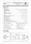
Utilizzare la TESTINA sempre entro i limiti di Pressione, Temperatura, Tensione previsti nelle CARATTERISTICHE TECNICHE di
questo manuale.
INSTALLAZIONE
Al fine di prevenire possibili danni alle persone ed alle cose, la TESTINA deve essere collegata ad un circuito di Pressione, in genere
alimentato da Pompe a pistoni, Idropulitrici e simili, dotato di tutti gli organi di sicurezza e controllo (come Valvole di regolazione, di
sicurezza etc.), previsti dalle normative vigenti per tali apparecchi. Per il collegamento utilizzare un tubo flessibile di adeguata sezione e
resistenza, evitando il più possibile strozzature e brusche variazioni di direzione per contenere le cadute di pressione.
La TESTINA deve essere ancorata saldamente all'imboccatura del serbatoio o ad apposito sostegno, gli ugelli si devono trovare
possibilmente al centro del serbatoio ed equidistanti dalle pareti.
SCELTA DEGLI UGELLI
Gli Ugelli (in numero di due) del tipo da lavaggio in alta pressione con getto rettilineo, dovranno essere adeguati alla Portata ed alla
Pressione alle quali si intende operare (vedi D2), tenendo presente che il valore della Pressione da considerare nella scelta è quello che
si ottiene sottraendo dal valore di Pressione nella pompa il valore della Caduta di Pressione determinata dalla linea di mandata e dalla
TESTINA.
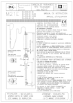
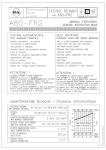
Quest'ultimo valore può essere ricavato dal diagramma D1 di questo manuale.
FUNZIONAMENTO
1) Collegare tubo alta pressione, collegare tubo raccolta scarico, collegare elettricamente.
2) Introdurre la testina nel recipiente da pulire (recipiente mancante di foro scarico).
3) Inserire il movimento di rotazione con apposito interruttore (lampadina accesa).
4) Aprire mandata acqua alta pressione e attendere la fine lavaggio ( 3 minuti min.). N.B. Sincerarsi che la manopola sia posizionata in
corrispondenza del lato (ON).
5) A lavaggio ultimato rimarrà sul fondo del recipiente un certo quantitativo di acqua causato dall’impatto del getto ad alta pressione, per
asportare anche questa quantità di acqua intervenire tramite la manopola, spostandola in corrispondenza del lato (OFF), questa
manovra chiude il flusso dell’acqua agli ugelli ma permette comunque il funzionamento dell’aspirazione, operazione necessaria per lo
svuotamento totale.
Prima di estrarre la testina dal contenitore sincerarsi che la mandata dell’acqua sia chiusa e che la lampadina indicatrice della rotazione
testina sia spenta.
N.B. TARARE LA VALVOLA DI MASSIMA ALLA PRESSIONE DI FUNZIONAMENTO DESIDERATA PRIMA DEL FUNZIONAMENTO
TESTINA SINCERANDOSI CHE ESISTA UN BY PASS DI ALMENO IL 5% DELLA PORTATA MASSIMA.
FILTRAGGIO
Il liquido inviato dal sistema alla testina va filtrato per impedire a corpi estranei di entrare , causa un cattivo funzionamento e di
conseguenza interventi di manutenzione più frequenti, il grado di filtraggio consigliato è almeno 300 micron.
MANUTENZIONE
Giornalmente dopo l’utilizzo normale eseguire un lavaggio interno della testina alimentandola con acqua pulita senza additivi.
Eseguire un controllo interno dopo 100 ore di lavoro per verificare le condizioni dei particolari interni (ingranaggi, cuscinetti, guarnizioni
dinamiche). La scelta errata del materiale dell’OR (guarnizioni dinamiche), causa un funzionamento anomalo e un rapido
deterioramento di questi particolari, in presenza di alterazioni dimensionali (Rigonfiamento) delle guarnizioni dinamiche (OR+PTFE).
Controllare la compatibilità dell’OR con i liquidi utilizzati, qualora non siano compatibili, contattare il nostro UFFICO TECNICO.
Eseguire un controllo interno ogni 300÷400 ore di lavoro, per verificare l’eventuale usura dei particolari interni. Si consiglia la
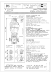
sostituzione delle guarnizioni dinamiche (pos.10 pos.12) verificando preventivamente che le superfici di scorrimento siano in buono
stato; se usurate sostituire.
Verificare inoltre le condizioni dei cuscinetti, delle boccole e degli ingranaggi ; se danneggiati sostituire.
Utilizzare esclusivamente ricambi originali ‘PA’.
Nelle zone e nei periodi dell'anno a rischio di gelo accertarsi, a fine lavoro, del completo svuotamento della TESTINA .
Lubrificare solo con grasso SILICONICO codice: 14.6552.00 , NON UTILIZZARE GRASSO O OLIO A BASE MINERALE, PENA LA
ROTTURA DEGLI ORGANI INTERNI.
AVVERTENZE SULLA SICUREZZA
- I getti di alta pressione possono essere pericolosi se soggetti ad uso non corretto. Il getto non deve essere diretto verso
persone o apparecchiature elettriche sotto tensione.
- Accertarsi che l'impianto di pompaggio sia dotato di una Valvola di sicurezza idonea alle prestazioni richieste.
- Per garantire la sicurezza dell'apparecchio usare solamente parti di ricambio originali PA o da essa approvati.
- Condotti per alta pressione, giunti e collegamenti sono importanti ai fini della sicurezza dell'apparecchio.
Usate solo condotti, giunti e collegamenti correttamente dimensionati e garantiti dal costruttore.
- METTERE IN FUNZIONE LA TESTINA SOLO DOPO AVERLA INSERITA E BLOCCATA AL SERBATOIO.
- TOGLIERE LA TESTINA DAL SERBATOIO SOLO DOPO AVERE DISINSERITA LA ROTAZIONE E L’ALIMENTAZIONE DEL
LIQUIDO DI LAVAGGIO.
- CON L’UTILIZZO DI LIQUIDO DI LAVAGGIO CALDO NON TOCCARE LE PARTI METALLICHE.
NORMATIVA
Le Testine oggetto del presente manuale hanno la marcatura CE, in quanto rispondenti alla Direttiva EMC 89/336 CEE, 92/31 CEE,
93/68 CEE ed alle norme applicate EN 55014, EN 55104, EN 61000-3-2,EN 61000-3-3.
12 - 4 M25E
ATTENTION !
The cleaning head is placed in rotation by an electric gear motor set positioned on the upper point that gives a high torque on exit.
Avoid possible jamming of the rotation from excess material.
UTILIZATION
This cleaning head is designed to be used with water up to 90º C - 194ºF, mixed with detergents or disinfectants of general use. Before
using specific liquids (high viscosity, very aggressive chemicals or else) consult our technical department.
Make sure the equipment is always used within the limits (Pressure, Temperature, Voltage) as specified in this manual.
INSTALLATION PROCEDURE
In order to avoid bodily injuries and damages to property, the cleaning head must always be connected to a pressure circuit, normally
fed by a piston pump, pressure washer or similar equipment, provided with all necessary safety and control features (safety valve,
pressure regulator etc..) requested by law for such appliances. For the connection make sure that a flexible hose with correct capacity
and resistance is used, avoiding sharp bends and variation of flow direction in order to reduce pressure drop.
The head must be firmly secured to the tank opening or a suitable support and the nozzles must preferably be in the centre of the tank
and equidistant from the tank walls.
CHOICE OF NOZZLES
The two solid stream spray nozzles for high pressure washing must be adequate to operating flow rate and pressure (see D2), bearing
in mind that the pressure value to be taken into consideration while choosing, is the one obtained by subtracting from the pump pressure
the loss of pressure determined by the delivery line and the head itself, the latter value can be obtained from diagram D1 in this manual.
WORKING
1)
2)
3)
4)
Connect the high pressure tube, the discharge tube and the electrical plug.
Insert the head inside the tank (tank without discharge hole).
Switch on the head (light on).
Open the high pressure delivery line and wait until the washing cycle ends (min. 3 minutes). REMARK: Please check that the
handle has been set in correspondence of the (ON) side.
5) At the end of the washing cycle you will notice that some water remains on the tank bottom : turn the handle towards the
(OFF)side. This operation closes the water flow to the nozzles, but permits the complete suction of the water out of the tank bottom.
This operation is necessary to empty the tank.
Before taking the head out of the tank, please check that the delivery line is closed and that the light (rotation indicator) is off.
N.B.: ADJUST THE VALVE AT THE REQUIRED WORKING PRESSURE BEFORE STARTING THE HEAD AND CHECK THAT 5%
OF THE MAXIMUM FLOW RATE FLOWS OUT IN BY-PASS.
FILTRATION
The fluid sent from the system to the cleaning head has to be filtered in order to prevent the entrance of any body matter due to bad
functioning which leads to frequent maintenance.
The degree of filtration recommended is at least 300 micron.
SERVICING
After a normal daily usage, wash the internal part of the head only with water minus any additives.
After 100 hours of labour, check the conditions of the internal parts (gears, dynamic seals).
The incorrect choice of the O-Ring material (dynamic seals) can cause an irregular function and a rapid deterioration of these parts.
In presence of dimensional alterations (swelling) of the dynamic seals (OR+PTFE) , control the compatibility of the O-Rings with the
liquids used.
If they result non-compatible, contact our TECHNICAL OFFICE.
Check the internal parts every 300÷400 hours of labour in order to verify any premature wear, especially the dynamic seals (pos.10 &
12), verify precautionally also the surface way if still in good shape, otheriwse replace if worn.
Check also the conditions of the bearing, bushings, gears, replace if damaged.
Use only original ‘PA’ spare parts.
If exposed to freezing temperatures make sure that the head is completely emptied after use in order to prevent freeze up.
Lubricate with P/N: 14.6552.00 SILICONE grease only, DO NOT USE MINERAL GREASE OR OIL, OTHERWISE RUPTURE OF THE
INTERNAL PARTS MAY OCCUR.
SAFETY INFORMATION
•
•
•
Improper use of high pressure jets can be very dangerous
Never point the jets towards people or electrical appliances
Make sure that the pumping system is equipped with suitable safety devices
Original PA parts only must be used for repair and servicing
High pressure pipes and connections are very important to the general safety of the equipment. Be sure to use only
components correctly sized and guaranteed by the manufacturer.
OPERATE THE HEAD ONLY AFTER IT HAS BEEN PLACED INTO THE TANK AND FIRMLY SECURED.
TAKE THE HEAD OUT OF THE TANK ONLY AFTER ROTATION AND WASHING WATER FEEDING HAVE BEEN STOPPED.
DO NOT TOUCH METAL PARTS WHEN USING HOT WASHING WATER.
STANDARDS
The cleaning heads described herein have the CEE marking as per the DIRECTIVE EMC89/366 CEE, 93/68 CEE and the standard
specifications EN55014, EN61000-3-2, EN55104
12 - 5 M25E
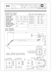
25.4380.00 M28E test.mot.elett+aspir.,fless.220V
25.4380.60 M28E test.mot.elett+aspir.,fless. USA
25.4385.00 Supporto esterno testina M28E
Aggiornato al 27/11/2015
Pos.
1
2
3
4
5
6
7
8
9
10
11
12
13
14
15
16
17
18
19
20
21
22
23
24
25
26
27
28
29
30
31
32
33
34
35
36
37
38
39
40
41
42
43
44
45
46
47
Codice
80.0330.81
80.0367.51
80.0371.21
80.0370.86
10.3007.10
80.0366.51
80.0328.51
80.0327.51
10.2030.00
80.0326.51
10.3055.10
80.0325.51
10.3010.10
80.0331.51
15.3704.00
10.2030.18
80.0024.85
10.3026.10
80.0372.23
80.0456.81
10.3206.10
80.0453.56
80.0458.56
80.0012.51
10.3205.10
80.0455.51
80.0454.31
80.0451.56
16.1852.10
80.0460.31
11.4412.28
10.3208.00
80.0510.53
16.2200.00
10.0999.05
80.0457.61
16.1860.00
80.0317.88
80.0459.41
80.0452.41
16.1832.00
14.4096.00
13.0829.00
80.0301.84
13.5997.00
12.5019.31
12.5019.25
Descrizione
Respingente forato POM bianco
Racc. M16x1 M inox
Molla inox
Tubo 10x12, 339mm PA bianco
An.OR 1x12 mm Vi 70
Racc. aspiraz. G1/4F-M16x1 M inox
Ghiera G1/4F inox
Perno porta guarnizioni inox
Guarn. stelo 15x20x2,2 mm +OR
Pignone portaug. z.41 M4 FF inox
An.OR 1,78x7,66 mm Vi 70
Perno M10x1 inox
An.OR 1x18 mm Vi 70
Statore inox
Tappo M4 plast.
Guarn. stelo 18x23x2 mm +OR Epdm
Boccola a. 18x22x14,8mm PTFE
An.OR 1,5x20 mm Vi 70
Pignone z.34 inox+Boccola a.15mm PTFE
Tappo conico 60mm
An.OR 2,62x28,25 mm Vi 70
Tubo G1/4 340mm inox
Tubo M28x1M 237mm inox
Ghiera M28x1 inox
An.OR 2,62x26,64 mm Vi 70
Pistone inox
Gomito ott. nichelato
Tubo Gc1/4MM 45 mm inox
Vite DIN912 M4x14 mm inox
Manicotto ott.nichelato
Cuscinetto 12x28x8 mm - 2RS1 inox
An. OR 2,62×34,59 mm
An. rasamento 12,3x17x0,5mm inox
Grano DIN913 M6x6 mm
An. elast. E 12 inox
Ingranaggio conico z:20
Vite DIN912 M4x60 mm inox
Guarniz. per motore, NBR
Flangia nera
Scatola
Vite ISO7380 M6x8 mm inox
Rosetta guarn. d.6 mm
Motoriduttore 12V 10Rpm
Carter motore PA nero
Pressacavo 1/4 +protezione
Lampada spia
Cavo 1x0,75 L.250 mm
Q.tà K1K2K3K4
1
5
1
1
1
1
1
1
2
•
10
1
1
1
5
1
5
2
•
4
1
3
1
•
10
1
1
2
•
10
1
1
2
4
3
•
5
1
5
1
•
10
1
3
1
1
2
•
10
1
1
1
1
1
1
1
•
10
1
1
1
1
1
1
12
10
1
1
1
3
1
•
10
1
5
2
10
1
10
2
1
2
10
2
2
1
1
1
1
1
10
1
4
1
1
1
1
1
5
1
5
1
5
Pos.
48
49
50
51
51
52
53
54
55
56
57
58
59
60
61
62
63
64
65
66
67
68
69
70
71
72
73
74
75
76
77
78
78
78
78
78
79
80
81
82
83
84
85
86
87
88
89
Codice
12.5016.10
12.5016.05
12.5019.47
12.5071.00
12.5071.60
12.5019.10
80.0338.31
10.3179.10
80.0337.56
80.0344.85
80.0346.35
80.0347.35
80.0336.31
80.0335.81
80.0334.31
10.3109.95
80.0333.31
10.3052.00
25.0019.51
80.0349.35
80.0348.31
80.0402.31
10.4058.00
10.3058.10
80.0403.21
29.0402.51
26.0252.51
26.0260.22
10.4010.01
26.0261.31
80.0400.00
80.0350.51
80.0351.51
80.0352.51
80.0353.51
80.0354.51
25.4367.24
25.4353.20
30.5061.84
12.8320.00
80.0463.51
80.0461.51
11.4627.50
80.0462.81
25.4385.00
14.3911.00
14.6552.00
Descrizione
Interr.unipol. on/off
Protezione interruttore
Rubacorrente
Trasf. 230Vca/12Vcc EU (1)
Trasf. 115Vca-60Hz/12Vcc USA (2)
Cavo 2x1,5 mm 10m+connessione F
Racc. M16x1 M ott.+Ni
An.OR 2,62x13,94 mm Vi 70
Tubo aspirazione G1/4M 113mm inox
Manopola 32x110mm PP nera
Gomito ptgm 20mm ott.+Ni
Girello G3/4 ott.+Ni
Racc. venturi ott.+Ni
An.conico a. 14x20x11mm POM bianco
Ghiera M24x1,5 ott.+Ni
An.OR 2,4x9,3 mm Vi 70
Racc. porta ugello G3/8M ott.+Ni
An.OR 1,78x6,75 mm
Ugello 02 d.10,5x15 mm inox
Racc. a T G3/8 FFF ott.+Ni
Racc. G3/8M-M22x1 M ott.+Ni
Racc. distrib. G3/8M-G1/4M ott.
An.tenuta 14x16x2 mm
An.OR 1,78x10,82 mm Vi 70
Manopola PA nera + Inserto ott.
An. elast. 1,6x14,3 mm inox
An. elast. 1,5x15,5 mm inox
Girello M22x1,5 17,5mm nero
An. anties. a. 10,2x13,9x1,2 mm
Spinotto 14mm-G1/4F ott.
Regolat. di portata RF1 G3/8M-G1/4M
Ugello 02 - 1,0mm - M4 inox verde ch.
Ugello 025 - 1,1mm - M4 inox rosa
Ugello 03 - 1,2mm - M4 inox bianco
Ugello 035 - 1,3mm - M4 inox marrone
Ugello 04 - 1,4mm - M4 inox giallo
Kit tubo aspirante M25E, 6×1pz.
Prol. -M21E 20m 12Vcc MF **
Appoggio (3)
Dado ad alette M6x1x10mm +vite (3)
Boccola inox (3)
Vite di guida inox (3)
Dado es. M10 inox (3)
Anello 62,8 mm plastica (3)
Supporto esterno testina M28E
Rosetta 13,5x19x1,5 mm Cu
Grasso silicone al teflon ×30g.>tutti imp. **
Q.tà
1
1
1
1
1
1
1
1
1
1
1
1
1
1
1
2
1
1
1
1
1
1
3
3
1
1
1
1
1
1
1
2
2
2
2
2
1
1
1
1
1
1
1
1
1
1
1
K1K2K3K4
•
•
•
•
•
•
•
•
•
•
•
** Su richiesta
Kit Codice
Descrizione
K1 25.4320.24 Kit Ugelli M4 - M21E 2x5pz.
K2 25.4382.24 Kit guarniz. M28E 1x15 pz.
1
1
(1) 25.4380.00 (2) 25.4380.60 (3) 25.4385.00
Aggiornato al 27/11/2015
3
5
5
1
1
5
10
10
3
5
3
5
3
10
5
25
3
25
5
3
3
3
10
10
3
5
10
10
50
10
3
10
10
10
10
10
1
1
5
3
3
3
10
3
1
10
2
25.4380.00 M28E Barrel cl.,el.driv+suct.,flex.220V
25.4380.60 M28E Barrel cl.,el.driv+suct.,flex.USA
25.4385.00 Holder for M28E-Barrel cleaner
Last updated 27/11/2015
Pos.
1
2
3
4
5
6
7
8
9
10
11
12
13
14
15
16
17
18
19
20
21
22
23
24
25
26
27
28
29
30
31
32
33
34
35
36
37
38
39
40
41
42
43
44
45
46
47
P/N
80.0330.81
80.0367.51
80.0371.21
80.0370.86
10.3007.10
80.0366.51
80.0328.51
80.0327.51
10.2030.00
80.0326.51
10.3055.10
80.0325.51
10.3010.10
80.0331.51
15.3704.00
10.2030.18
80.0024.85
10.3026.10
80.0372.23
80.0456.81
10.3206.10
80.0453.56
80.0458.56
80.0012.51
10.3205.10
80.0455.51
80.0454.31
80.0451.56
16.1852.10
80.0460.31
11.4412.28
10.3208.00
80.0510.53
16.2200.00
10.0999.05
80.0457.61
16.1860.00
80.0317.88
80.0459.41
80.0452.41
16.1832.00
14.4096.00
13.0829.00
80.0301.84
13.5997.00
12.5019.31
12.5019.25
Description
Pierced buffer, POM white
Coupl., M16x1 M Sst.
Spring, Sst.
Hose, 10x12, 339mm PA white
O-ring, 1x12 mm Vi 70
Suction coupl., 1/4F Bsp-M16x1 M Sst.
Ring nut, 1/4F Bsp Sst.
Seal holding pin, Sst.
Stem seal, 15x20x2,2 mm +O-ring
Nzl hold. pinion, z.41 M4 FF Sst.
O-ring, 1,78x7,66 mm Vi 70
Pin, M10x1 Sst.
O-ring, 1x18 mm Vi 70
Stator, Sst.
Plug, M4 plast.
Stem seal, 18x23x2 mm +O-ring Epdm
Bushing, opn. 18x22x14,8mm PTFE
O-ring, 1,5x20 mm Vi 70
Pinion, z.34 Sst.+bushing,opn.15mm PTFE
Tapered plug, 60 mm
O-ring, 2,62x28,25 mm Vi 70
Tube, G1/4 340mm Sst.
Tube, M28x1M 237mm Sst.
Ring nut, M28x1 Sst.
O-ring, 2,62x26,64 mm Vi 70
Piston, Sst.
Elbow, nickel-plated brass
Tube, 1/4MM Bspt 45 mm Sst.
Screw, DIN912 M4x14 mm Sst.
Coupling, nickel-plated brass
Ball-bearing, 12x28x8 mm - 2RS1 Sst.
O-ring, 2,62×34,59 mm
Shim ring, 12,3x17x0,5mm Sst.
Set screw, DIN913 M6x6 mm
Snap ring, E 12 Sst.
Tapered gear, z:20
Screw, DIN912 M4x60 mm Sst.
Motor seal, NBR
Flange, black
Casing
Screw, ISO7380 M6x8 mm Sst.
Sealing washer, d.6 mm
Gearmotor, 12V 10Rpm
Motor casing, PA black
Cable gland 1/4 +protection
Pilot lamp
Cable, 1x0,75 L.250 mm
Q.ty K1K2K3K4
1
5
1
1
1
1
1
1
2
•
10
1
1
1
5
1
5
2
•
4
1
3
1
•
10
1
1
2
•
10
1
1
2
4
3
•
5
1
5
1
•
10
1
3
1
1
2
•
10
1
1
1
1
1
1
1
•
10
1
1
1
1
1
1
12
10
1
1
1
3
1
•
10
1
5
2
10
1
10
2
1
2
10
2
2
1
1
1
1
1
10
1
4
1
1
1
1
1
5
1
5
1
5
Pos.
48
49
50
51
51
52
53
54
55
56
57
58
59
60
61
62
63
64
65
66
67
68
69
70
71
72
73
74
75
76
77
78
78
78
78
78
79
80
81
82
83
84
85
86
87
88
89
P/N
12.5016.10
12.5016.05
12.5019.47
12.5071.00
12.5071.60
12.5019.10
80.0338.31
10.3179.10
80.0337.56
80.0344.85
80.0346.35
80.0347.35
80.0336.31
80.0335.81
80.0334.31
10.3109.95
80.0333.31
10.3052.00
25.0019.51
80.0349.35
80.0348.31
80.0402.31
10.4058.00
10.3058.10
80.0403.21
29.0402.51
26.0252.51
26.0260.22
10.4010.01
26.0261.31
80.0400.00
80.0350.51
80.0351.51
80.0352.51
80.0353.51
80.0354.51
25.4367.24
25.4353.20
30.5061.84
12.8320.00
80.0463.51
80.0461.51
11.4627.50
80.0462.81
25.4385.00
14.3911.00
14.6552.00
Description
On/off unipol. switch
Switch protector
Wire tap-in
Transf. 230VAC/12VDC EU (1)
Transf. 115VAC-60Hz/12VDC USA (2)
Cable, 2x1,5 mm 10m+F connection
Coupl., M16x1 M brass+Ni
O-ring, 2,62x13,94 mm Vi 70
Intake tube, 1/4M Bsp 113mm Sst.
Knob, 32x110mm PP black
Elbow+hose barb, 20mm brass+Ni
Hand nut, G3/4 brass+Ni
Venturi fitting, brass+Ni
Taper.ring,opn. 14x20x11mm POM white
Ring nut, M24x1,5 brass+Ni
O-ring, 2,4x9,3 mm Vi 70
Nozzle holder, 3/8M Bsp brass+Ni
O-ring, 1,78x6,75 mm
Nozzle, 02 d.10,5x15 mm Sst.
T-fitting, 3/8Bsp FFF brass+Ni
Coupl., 3/8M Bsp-M22x1 M brass+Ni
Slide valve, 3/8M-1/4M Bsp brass
Back-up ring, opn. 14x16x2 mm
O-ring, 1,78x10,82 mm Vi 70
Knob, PA black + Insert, brass
Snap ring, 1,6x14,3 mm Sst.
Snap ring, 1,5x15,5 mm Sst.
Hand nut, M22x1,5 - 17,5mm black
Back-up ring,10,2x13,9x1,2mm
Plug, 14mm-1/4F Bsp brass
Flow regulator -RF1, 3/8M -1/4M Bsp
Nozzle, 02 - 1,0mm - M4 Sst. light green
Nozzle, 025 - 1,1mm - M4 Sst. pink
Nozzle, 03 - 1,2mm - M4 Sst. white
Nozzle, 035 - 1,3mm - M4 Sst. brown
Nozzle, 04 - 1,4mm - M4 Sst. yellow
Suction tube kit -M25E, 6×1pcs.
Exten.-M21E 20m 12V DC MF **
Rest (3)
Wing nut, M6x1x10mm +screw (3)
Bushing, Sst. (3)
Guide screw, Sst. (3)
Hex. nut, M10, Sst. (3)
Ring, 62,8 mm plastic (3)
Holder for M28E-Barrel cleaner
Washer, 13,5x19x1,5 mm Cu
Teflon silicon grease ×30g.>All **
Q.ty
1
1
1
1
1
1
1
1
1
1
1
1
1
1
1
2
1
1
1
1
1
1
3
3
1
1
1
1
1
1
1
2
2
2
2
2
1
1
1
1
1
1
1
1
1
1
1
K1K2K3K4
•
•
•
•
•
•
•
•
•
•
•
** On request
Kit
P/N
Description
K1 25.4320.24 Nozzle kit M4 - M21E 2x5pcs.
K2 25.4382.24 Seals kit -M28E, 1x15 pcs.
1
1
(1) 25.4380.00 (2) 25.4380.60 (3) 25.4385.00
Last updated 27/11/2015
3
5
5
1
1
5
10
10
3
5
3
5
3
10
5
25
3
25
5
3
3
3
10
10
3
5
10
10
50
10
3
10
10
10
10
10
1
1
5
3
3
3
10
3
1
10
2
NOTE
NOTES
__
NOTE
NOTES
__
P.A. SpA EQUIPAGGIAMENTI TECNICI DEL LAVAGGIO
Via Milano, 13 42048 Rubiera - (RE) ITALY
Tel +39 0522 623611 (ric aut) - Fax +39 0522 629600
[email protected] - www.pa-etl.it