1
Version: 08 - 01 - 2009
IT
GB
DE
FR
ES
Code: 7NU0309AG52
MANUALE D’USO E MANUTENZIONE
ARMADIO
ABBATTITORE/CONGELATORE...........pagina
USE AND MAINTENANCE MANUAL
BLAST CHILLER/SHOCK FREEZER...................page
GEBRAUCHS UND WARTUNGSHANDBUCH
ABKÜHL/GEFRIERSCHRANK........................seite
MANUEL D’UTILISATION ET D’ENTRETIEN ARMOIRS
REFROIDISSEMENT ET DE CONGELATION RAPIDE....page
MANUAL USO Y MANTENIMIENTO
CELDA ABATIDORA/COGLADORA.....................páge
3
17
31
45
59
3 - IT
INDICE
1. NORME DI AVVERTENZE GENERALI
1.1. Collaudo
1.2. Garanzia
1.3. Premessa
1.4. Predisposizione a carico cliente
1.5. Istruzione per richiesta interventi
1.6. Istruzioni per ricambi
2. DATI TECNICI
2.1. Livello rumorosità
2.2. Materiali e fluidi impiegati
3. FUNZIONAMENTO
3.1. Applicazioni, destinazione d’uso, uso previsto e non
previsto, usi consuetudini
3.2. Zone pericolose
3.3. Dispositivi di sicurezza addottati
4. MANUTENZIONE ORDINARIA E PROGRAMMATA
4.1. Elementi norme di sicurezza
4.2. Indicazioni sulle operazioni di emergenza in caso di
incendio
4.3. Pulizia dell’apparecchiatura
4.4. Verifiche periodiche da eseguire
4.5. Precauzioni in previsione di lunga inttività
4.6. Manutenzione straordinaria
5. SMALTIMENTO RIFIUTI E DEMOLIZIONE
5.1. Stoccaggio dei rifiuti
5.2. Procedura riguardante le macro operazioni di smontaggio
dell’apparecchiatura
6. INSTALLAZIONE
6.1. Trasporto del prodotto, movimentazione
6.2. Descrizioni delle operazioni di messa in opera
6.3. Posizionamento
6.4. Allacciamento
6.5. Reinstallazione
7. ISTRUZIONI PER L’UTILIZZATORE
7.1. Pannello di controllo
7.2. Programmazione orologio per HACCP
7.3. Cicli di funzionamento
7.3.0. Accensione
7.3.1. Ciclo di abbattimento +3°C soft o hard e
congelamento -18°C soft o hard a tempo
7.3.2. Ciclo di abbattimento +3°C soft o
hard e congelamento -18°C soft o hard a spillone
7.3.3. Ciclo di abbattimento/congelmento con 2 - 3
- 4 sonde spillone standard
7.3.4. Cicli di abbattimento/congelamento personalizzati
7.3.5. Fase di conservazione
7.3.6. Memorizzazione di un programma di
abbattimento/congelamento
7.3.7. Richiamo di un programma di abbattimento/
congelamento memorizzato
7.4. Sbrinamento
7.5. Sterilizzazione (optional)
7.6. Stampante (optional)
7.7. Allarmi/Errori
7.7.1. Allarme alta temperatura
7.7.2. Allarme bassa temperatura
7.7.3. Allarme porta aperta
7.7.4. Allarme pressostato
7.7.5. Allarme timeout
7.7.6. Allarme blackout
7.7.7. Allarme sonda cella
7.7.8. Allarme sonda spillone
7.7.9. Allarme sonda evaporatore
7.8. HACCP
7.8.1. Reset Allarmi HACCP
1. NORME E AVVERTENZE GENERALI
1.1. COLLAUDO
Il prodotto viene spedito dopo il superamento dei collaudi: visivo, elettrico e funzionale.
1.2. GARANZIA
Il nostro obbligo per la garanzia sulle apparecchiature e sulle parti relative di nostra produzione ha la durata di 1 anno, dalla data della fattura
e consiste nella fornitura gratuita delle parti da sostituire che, a nostro
insindacabile giudizio, risultassero difettose.
Sarà premura del costruttore rimuovere eventuali vizi e difetti purché
l’apparecchiatura sia stata impiegata correttamente nel rispetto delle indicazioni riportate nel manuale.
Durante il periodo di garanzia saranno a carico del committente le spese
concernenti le prestazioni d’opera, viaggi o trasferte, trasporto delle parti
ed eventuali apparecchiature da sostituire. I materiali sostituiti in garanzia restano di nostra proprietà e devono essere restituiti a cura e spese
del committente.
1.3. PREMESSA
Il presente manuale ha lo scopo di fornire tutte le informazioni necessarie per effettuare correttamente l’installazione, l’uso e la manutenzione
dell’apparecchiatura da parte di personale qualificato.
Prima di ogni operazione bisogna leggere attentamente le istruzioni contenute, in quanto forniscono indispensabili indicazioni riguardanti lo stato
di sicurezza delle apparecchiature.
IL COSTRUTTORE DECLINA OGNI RESPONSABILITA’ DA USI NON PREVISTI DEL PRODOTTO.
E’ VIETATA LA RIPRODUZIONE, ANCHE IN PARTE, DEL PRESENTE MANUALE.
NORME DI SICUREZZA GENERALE
Il costruttore declina ogni responsabilità per qualsiasi operazione effettuata sull’apparecchiatura trascurando le indicazioni riportate sul manuale.
Prima del collegamento alla rete di alimentazione elettrica
assicurarsi che la tensione e la frequenza di rete corrispondano a quelle
riportate sulla targhetta caratteristiche.
Collegare sempre l’apparecchiatura ad un apposito interruttore magnetotermico differenziale ad alta sensibilità
(30 mA).
Prima di effettuare qualsiasi operazione di pulizia o di manutenzione, disinserire l’apparecchiatura dalla rete di alimentazione
elettrica: 1) Portare l’interruttore generale nella posizione OFF;
2) Togliere la spina.
Munirsi di guanti per effettuare la manutenzione sul vano motore o sull’unità evaporante posta all’interno dell’apparecchiatura.
Non inserire cacciaviti od altro tra le protezioni (protezioni ventilatori, evaporatori, ecc.).
scalzi.
Non avvicinarsi alle parti elettriche con mani bagnate oppure
Per una buona funzionalità del gruppo compressore ed evaporatore non ostruire mai le apposite prese d’aria.
Nelle apparecchiature dotate di ruote verificare che la superficie di appoggio sia piana e perfettamente orizzontale.
Nelle apparecchiature dotate di serratura con chiave si consiglia di tenere le chiavi lontano dalla portata dei bambini.
IT - 4
L’utilizzo è riservato solamente a personale idoneo e addestrato.
L’installazione, la manutenzione ordinaria e la manutenzione
straordinaria (esempio pulizia e manutenzione dell’impianto refrigerante)
devono essere eseguite da personale tecnico specializzato ed autorizzato
con buona conoscenza degli impianti di refrigerazione ed elettrici.
1.4. PREDISPOSIZIONE A CARICO DEL CLIENTE
Predisporre un interruttore magnetotermico differenziale ad alta sensibilità (30 mA).
Predisporre una presa di corrente con terra del tipo in uso nel paese di
utilizzo.
Verificare la planarità della superficie di appoggio della macchina.
Predisporre, nel caso di apparecchiature con condensazione ad acqua o
di apparecchiature con controllo diretto dell’umidità, l’allacciamento alla
rete idrica.
1.5. ISTRUZIONI PER RICHIESTA INTERVENTI
Spesso le difficoltà di funzionamento che si possono verificare sono
dovute a cause banali quasi sempre rimediabili di persona, quindi prima
di richiedere l’intervento di un tecnico fate le seguenti semplici verifiche:
IN CASO DI ARRESTO DELL’APPARECCHIO:
- controllare che la spina sia inserita correttamente nella presa di corrente.
IN CASO DI TEMPERATURA CELLA INSUFFICIENTE:
- verificare che non ci sia influenza di una fonte di calore;
- verificare che le porte chiudano perfettamente;
- verificare che il filtro del condensatore non sia intasato;
- verificare che le griglie di aerazione del cruscotto non siano ostruite;
- verificare la disposizione delle derrate affinché non ostruiscano la ventilazione all’interno della cella.
IN CASO DI APPARECCHIO RUMOROSO:
- verificare che non ci sia contatto incerto fra l’apparecchio e qualche
altro oggetto;
- verificare che l’apparecchio sia perfettamente livellato;
- verificare che le viti (almeno quelle visibili) siano ben serrate. Eseguite
le verifiche suddette, se il difetto persiste, rivolgetevi all’assistenza tecnica ricordandovi di segnalare:
- la natura del difetto;
- il codice ed il numero di matricola dell’apparecchio che si possono rilevare dalla targhetta caratteristiche dello stesso.
1.6. ISTRUZIONI PER I RICAMBI
Si raccomanda l’impiego di RICAMBI ORIGINALI.
Il costruttore declina ogni responsabilità per l’impiego di ricambi non
originali.
2. DATI TECNICI
La targhetta dati è posizionata esternamente sul fianco o sul retro ed
internamente sul vano motore.
2.1. LIVELLO DI RUMOROSITA’
Leq nel punto più rumoroso a 1 mt. in condizioni operative < 70 dB (A)
Lpc a 1 mt. in condizioni operative
< 130 dB (C)
AMBIENTE DI PROVA
La prova e stata eseguita all’interno di una sala di esposizione di forma
rettangolare priva di trattamenti fono-assorbenti.
Nello spazio circostante la macchina erano assenti ostacoli rilevanti.
NORMATIVE DI RIFERIMENTO
I rilievi delle prove acustiche sono stati effettuati in conformità al D.L.277
seguendo le modalità descritte dalle ISO 230-5 per rilevare i dati richiesti
dalla direttiva CEE 89/392.
CONDIZIONI OPERATIVE DELLA MACCHINA
I rilievi sono stati eseguiti nella condizione più gravosa che corrisponde
alla fase di partenza denominata “PULL DOWN”.
2.2. MATERIALI E FLUIDI IMPIEGATI
I materiali utilizzati sono conformi al D.Lgs 25 luglio 2005, n.151 in attuazione delle direttive 2002/95/CE, 2002/96/CE e 2003/108/CE, relative alla riduzione dell’uso di sostanze pericolose nelle apparecchiature
elettriche ed elettroniche, nonché allo smaltimento dei rifiuti.
3. FUNZIONAMENTO
3.1. APPLICAZIONI, DESTINAZIONE D’USO, USO PREVISTO E NON PREVISTO, USI CONSENTITI
Le nostre apparecchiature frigorifere sono macchine agroalimentari
(Regolamento CE n° 1935/2004), destinate al trattamento dei prodotti
alimentari.
Sono progettate con gli opportuni accorgimenti al fine di garantire la
sicurezza e la salute dell’utilizzatore.
IMPIEGO DELL’ ABBATTITORE-CONGELATORE:
L’abbattitore-congelatore è un’apparecchiatura che abbassa rapidamente
la temperatura dei cibi cotti o freschi, allo scopo di mantenere inalterate le proprietà organolettiche (chimico-fisiche e nutritive) degli alimenti
stessi.
Il tempo di raffreddamento o di congelamento, essendo in funzione del tipo di alimento o degli alimenti presenti in un piatto cucinato (densità, porzioni), è un parametro variabili difficile da stabilire rigorosamente. Le prestazioni dichiarate sono state ottenute
con purè di patate, depositato in teglie di acciaio GN1/1 H=40. Lo
spessore del purè contenuto nelle vaschette è di 25mm.
CICLO DI ABBATTIMENTO RAPIDO DI TEMPERATURA:
Mediante questo ciclo è possibile abbassare rapidamente la temperatura
dell’alimento cotto (da +90 a +3°C in 90 minuti) per evitare che rimanga
nella zona critica di temperatura tra +10°C a +65°C.
L’alimento cotto e abbattuto può essere conservato in frigorifero fino a
5 giorni.
CICLO DI CONGELAMENTO RAPIDO DI TEMPERATURA:
Il congelamento rapido di temperatura (da +90°C a -18°C) impedisce la
formazione di macrocristalli di ghiaccio nell’alimento, che comporterebbero perdita di liquidi e vitamine.
Questo ciclo è indicato sia per alimenti cotti che freschi e consente la loro
conservazione rispettivamente fino a 2 mesi e fino a 12 mesi.
CICLO DI CONSERVAZIONE:
Alla fine di ogni ciclo di abbattimento o congelamento rapido la macchina
prevede un ciclo di conservazione durante il quale l’apparecchiatura funziona come un normale refrigeratore, la durata di tale ciclo è a discrezione dell’utente.
STOCCAGGIO DEGLI ALIMENTI
Allo scopo di ottenere le migliori prestazioni dell’apparecchiatura è necessario rispettare le seguenti indicazioni:
Ciclo di conservazione:
- Non introdurre all’interno dell’apparecchiatura cibi caldi o liquidi
scoperti;
- Confezionare o proteggere gli alimenti soprattutto se contengono
aromi;
- Sistemare le derrate all’interno dell’apparecchiatura in modo da non
limitare la circolazione dell’aria, evitando di disporre sulle griglie carte,
cartoni, taglieri, ecc., che possono ostacolare il passaggio dell’aria;
- Evitare il più possibile frequenti e prolungate aperture porta.
Ciclo di abbattimento/congelamento rapido:
- Non aprire la porta una volta avviato il ciclo e sino a ciclo terminato;
- Evitare di confezionare, proteggere o chiudere le teglie con coperchi o
pellicole isolanti;
- Non usare teglie e contenitori con altezza superiore a 65mm;
- Non sovrapporre gli alimenti;
- Utilizzare contenitori in alluminio o in acciaio inox.
3.2. ZONE PERICOLOSE, RISCHI, PERICOLI E RISCHI
NON ELIMINABILI
Le apparecchiature frigorifere sono state realizzate e progettate con
gli opportuni accorgimenti al fine di garantire la sicurezza e la salute
dell’utilizzatore e non presentano spigoli pericolosi, superfici affilate o
elementi sporgenti dagli ingombri.
La loro stabilità è garantita anche a porte aperte, è vietato comunque
attaccarsi alle porte.
Nelle apparecchiature con cassetti non aprire più di un cassetto alla volta
e non appoggiarsi o sedersi sul cassetto aperto per evitare sia il ribaltamento che il danneggiamento dell’apparecchiatura.
5 - IT
N.B.: Nelle apparecchiature porte vetro non estrarre più di un cestello, oppure una griglia alla volta, per non compromettere la stabilità
dell’apparecchiatura.
Disporre gradualmente gli alimenti partendo dal basso verso l’alto; viceversa togliere gli alimenti partendo dall’alto verso il basso.
LA MACCHINA NON E’ STATA PROGETTATA PER ESSERE INSTALLATA IN
UNA ATMOSFERA A RISCHIO DI ESPLOSIONE.
Carico massimo (uniformemente distribuito) per cestello, cassetto o griglia = kg 40
APPARECCHIATURA CON RUOTE
Fare attenzione, durante gli spostamenti, a non spingere violentemente l’apparecchiatura per evitare che si ribalti e si danneggi, fare attenzione anche alle eventuali asperità della superficie di scorrimento.
L’apparecchiatura dotata di ruote non può essere livellata, quindi fare
attenzione che la superficie di appoggio sia perfettamente orizzontale e
piana.
BLOCCARE SEMPRE LE RUOTE CON GLI APPOSITI FERMI.
RISCHI DOVUTI AD ELEMENTI MOBILI
L’unico elemento mobile presente è il ventilatore, ma non presenta alcun rischio in quanto è protetto da griglia di protezione fissata tramite
viti (prima di rimuovere tale protezione scollegare l’apparecchiatura dalla
rete di alimentazione).
RISCHI DOVUTI ALLE BASSE/ELEVATE TEMPERATURE
In prossimità delle zone con pericolo di temperature basse/elevate, sono
stati apposti degli adesivi indicanti “PERICOLO TEMPERATURA”.
RISCHI DOVUTI ALL’ENERGIA ELETTRICA
I rischi di natura elettrica sono stati risolti progettando gli impianti elettrici secondo la norma CEI EN 60204-1 e CEI EN 60335-1.
Appositi adesivi indicanti “alta tensione” individuano le zone con pericoli
di natura elettrica.
RISCHI DOVUTI AL RUMORE
Leq nel punto più rumoroso a 1 mt. in condizioni operative < 70 dB(A)
Lpc a 1 mt. in condizioni operative
< 130 dB(C)
RISCHI RESIDUI
Per consentire ad eventuali liquidi provenienti dagli alimenti o dai prodotti di lavaggio di defluire verso l’esterno, si è realizzata sul fondo una
piletta di scarico. Durante le operazioni di pulizia bisognerà togliere il
tappo e posizionare sotto l’apparecchiatura una bacinella di raccolta
(hmax=100mm).
E’ ASSOLUTAMENTE IMPORTANTE RICHIUDERE IL FORO CON
L’APPOSITO TAPPO. NEL CASO DEGLI APPARECCHI SENZA PILETTA DI SCARICO BISOGNA EVITARE QUALSIASI RISTAGNO
DI LIQUIDI TRAMITE UNA ACCURATA PULIZIA GIORNALIERA.
3.3. DISPOSITIVI DI SICUREZZA ADOTTATI
E’ ASSOLUTAMENTE VIETATO MANOMETTERE OD ASPORTARE I DISPOSITIVI DI SICUREZZA ADOTTATI (GRIGLIE
DI PROTEZIONE, ADESIVI DI PERICOLO,...). IL COSTRUTTORE
DECLINA OGNI RESPONSABILITÁ SE NON VENGONO RISPETTATE LE ISTRUZIONI SUDDETTE.
E’ assolutamente vietato manomettere od asportare i dispositivi di sicurezza adottati (griglie di protezione, adesivi di pericolo...).
Il costruttore declina ogni responsabilità se non vengono rispettate le
istruzioni suddette.
4. MANUTENZIONE ORDINARIA E PROGRAMMATA
Le informazioni contenute in questo capitolo sono destinate, per quanto
riguarda la manutenzione ordinaria, a personale idoneo e addestrato, per
quanto riguarda la manutenzione straordinaria e/o programmata, sono
destinate a personale specializzato ed autorizzato.
4.1. ELEMENTARI NORME DI SICUREZZA
Prima di eseguire qualsiasi intervento, disinserire
dell’apparecchiatura dalla rete di alimentazione elettrica.
la
spina
DIVIETO DI RIMOZIONE DEI RIPARI O DEI DISPOSITIVI DI SICUREZZA
Per le operazioni di manutenzione ordinaria, è vietato rimuovere i ripari/
dispositivi di sicurezza (griglie, adesivi, ecc.).
4.2. INDICAZIONI SULLE OPERAZIONI DI EMERGENZA
IN CASO DI INCENDIO
ATTENZIONE:
In caso di incendio non usare acqua.
Premunirsi di estintore a CO2 (anidride carbonica) e raffreddare nel più
breve tempo possibile la zona del vano motore.
4.3. PULIZIA DELL’APPARECCHIATURA
Prima di qualsiasi operazione di pulizia, isolare l’apparecchiatura
dall’energia elettrica.
PRIMA INSTALLAZIONE
Prima della messa in funzione lavare l’interno cella e gli accessori con
poca acqua e sapone neutro per togliere il caratteristico odore di nuovo; sistemare gli accessori interni della cella nelle posizioni più consone
all’uso.
PULIZIA GIORNALIERA
Pulire accuratamente le superfici esterne dell’apparecchiatura usando un
panno umido e seguendo il senso della satinatura.
Usare detersivi neutri e non sostanze a base di cloro e/o abrasive.
Non usare utensili che possono provocare incisioni con la conseguente
formazione di ruggine. Risciacquare con acqua pura ed asciugare accuratamente.
Pulire l’interno cella per evitare che si formino residui di sporco, con detersivi neutri non contenenti cloro e abrasivi. Nel caso di residui induriti
usare acqua e sapone o detergenti neutri, servendosi eventualmente di
una spatola in legno o plastica.
Terminata la pulizia risciacquare con poca acqua e asciugare accuratamente.
Non lavare l’apparecchiatura con getti d’acqua diretti, poiché eventuali
infiltrazioni nei componenti elettrici potrebbero pregiudicarne il regolare
funzionamento.
Anche le zone sottostanti e adiacenti l’apparecchiatura devono essere
giornalmente pulite, sempre con acqua e sapone e non con detersivi tossici o a base di cloro.
PULIZIA PERIODICA MANUTENZIONE GENERALE
Per un costante rendimento dell’apparecchiatura è bene compiere le
operazioni di pulizia e manutenzione generale.
Per quanto riguarda la pulizia del gruppo frigorifero (condensatore), deve
essere fatta da personale specializzato.
Pulire periodicamente la piletta di scarico per evitare che il foro si ostruisca.
E’ ASSOLUTAMENTE IMPORTANTE RICHIUDERE IL FORO CON
L’APPOSITO TAPPO.
4.4. VERIFICHE PERIODICHE DA ESEGUIRE
- Controllare che la spina sia inserita correttamente nella presa di corrente.
- Verificare che non ci sia influenza di una fonte di calore.
- Verificare che l’apparecchio sia perfettamente livellato.
- Verificare che la guarnizione della porta chiuda perfettamente.
- Verificare che la piletta di scarico non sia ostruita.
- Verificare che la batteria condensante non sia ricoperta di polvere, nel
caso chiamare l’assistenza tecnica.
4.5. PRECAUZIONI IN VISTA DI LUNGA INATTIVITÁ
In caso di prevista prolungata inattività dell’apparecchiatura:
- spegnere l’apparecchiatura agendo nel pannello comandi sul tasto OFF;
- togliere la spina dalla presa di alimentazione;
- vuotare il frigorifero e pulirlo accuratamente (vedi pulizia);
- Lasciare le porte del mobile socchiuse per favorire la circolazione
dell’aria ed evitare la formazione di muffe e/o cattivi odori.
4.6. MANUTENZIONE STRAORDINARIA
(solo per personale specializzato)
- Pulire periodicamente il condensatore.
IT - 6
- Controllare le guarnizioni delle porte, per verificare la perfetta tenuta.
- Controllare che l’impianto elettrico sia a norma.
- Controllare le resistenze cornici (mediante pinza amperometrica).IN
CASO DI RIPARAZIONE O SOSTITUZIONE DI PARTI RICORDARSI DI FORNIRE SEMPRE IL CODICE ED IL NUMERO DI MATRICOLA DELL’APPARECCHIATURA, CHE SI POSSONO RILEVARE
DALLA TARGHETTA CARATTERISTICHE.
5. SMALTIMENTO RIFIUTI E DEMOLIZIONE
5.1. STOCCAGGIO DEI RIFIUTI
E’ ammesso uno stoccaggio provvisorio di rifiuti speciali in vista di uno
smaltimento mediante trattamento e/o stoccaggio definitivo. Vanno comunque osservate le leggi vigenti nel paese dell’utilizzatore in materia di
tutela dell’ambiente.
5.2. PROCEDURA RIGUARDANTE LE MACRO OPERAZIONI DI SMONTAGGIO DELL’APPARECCHIATURA
Nei vari Paesi sono in vigore legislazioni differenti, pertanto si devono
osservare le prescrizioni imposte dalle leggi e dagli enti preposti dai Paesi
dove avviene la demolizione.
In generale bisogna riconsegnare il frigorifero al rivenditore oppure ai
centri specializzati per la raccolta/demolizione.
Smontare il frigorifero raggruppando i componenti secondo la loro natura
chimica, ricordando che nel compressore vi è olio lubrificante e fluido refrigerante, che possono essere recuperati e riutilizzati e che i componenti
del frigorifero sono rifiuti speciali assimilabili agli urbani.
LE OPERAZIONI DI SMONTAGGIO DEVONO COMUNQUE ESSERE ESEGUITE DA PERSONALE QUALIFICATO.
DURANTE GLI SPOSTAMENTI NON SPINGERE O TRASCINARE
L’APPARECCHIATURA PER EVITARE CHE SI RIBALTI O CREARE DANNI AD
ALCUNE PARTI DELLO STESSO (AD ESEMPIO I PIEDINI).
NON INCLINARE MAI L’APPARECCHIATURA DAL LATO PORTA.
6.3. POSIZIONAMENTO
Posizionare l’apparecchiatura in luogo ben aerato e lontano da fonti di
calore. Rispettare degli spazi minimi per il funzionamento, l’aerazione e
la manutenzione.
APPARECCHIATURA CON RUOTE
L’apparecchiatura dotata di ruote non può essere livellata, quindi fare
attenzione che la superficie di appoggio sia perfettamente orizzontale e
piana.
DOPO AVER POSIZIONATO L’APPARECCHIATURA BLOCCARE
SEMPRE LE RUOTE.
DURANTE GLI SPOSTAMENTI NON SPINGERE VIOLENTE
MENTE O TRASCINARE L’APPARECCHIATURA PER EVITARE CHE SI
RIBALTI O SI DANNEGGI. FARE ATTENZIONE ALLE EVENTUALI ASPERITA’
DELLA SUPERFICIE. NON INCLINARE MAI L’APPARECCHIATURA DAL
LATO PORTA.
6. INSTALLAZIONE
(solo personale tecnico specializzato)
LA MACCHINA NON E’ STATA PROGETTATA PER ESSERE
INSTALLATA IN UNA ATMOSFERA A RISCHIO DI ESPLOSIONE.
6.1. TRASPORTO DEL PRODOTTO, MOVIMENTAZIONE
L’apparecchiatura deve essere trasportata con mezzi idonei alla movimentazione e mai a mano.
Se si usano sistemi di sollevamento, quali carrelli a forche o transpallet,
fare particolare cura al bilanciamento del peso.
Normalmente l’imballo è di polistirolo ed estensibile su pallet in legno che,
per una maggiore sicurezza durante il trasporto e lo spostamento, viene
fissato al fondo dell’apparecchiatura.
Sull’imballo vengono stampati dei contrassegni di avvertimento, che rappresentano le prescrizioni che devono essere osservate al fine di assicurare che nelle operazioni di carico e scarico, nel trasporto e nello la merce
non subisca danni.
6.4. ALLACCIAMENTO
Prima del collegamento alla rete di alimentazione elettrica, assicurarsi che
la tensione e la frequenza di rete corrispondano a quelle riportate nella
targhetta caratteristiche dell’apparecchiatura.
E’ ammessa una variazione +/-10% della tensione nominale.
E’ indispensabile collegare l’apparecchiatura ad una efficiente presa di
terra.
CONTRASSEGNI STAMPATI SUI NOSTRI IMBALLI
(UNI 6720-70):
ALTO
FRAGILE
TENERE ALL’ASCIUTTO
Per lo smaltimento dell’imballo l’utilizzatore dovrà comportarsi secondo
le norme vigenti nel proprio paese.
LIMITI DI IMPILABILITÀ
Per quanto riguarda lo stoccaggio e il trasporto dell’apparecchiatura, il
limite di impilabilità massimo è due apparecchiature salvo indicazione con
apposito adesivo
A CAUSA DEL BARICENTRO NON COINCIDENTE CON IL CENTRO GEOMETRICO DELL’APPARECCHIATURA, FARE ATTENZIONE ALL’INCLINAZIONE
DURANTE GLI SPOSTAMENTI.
6.2. DESCRIZIONI DELLE OPERAZIONI DI MESSA IN
OPERA
Si consiglia dopo aver tolto l’imballo dall’apparecchiatura di verificare
l’integrità e l’assenza di danni dovuti al trasporto.
Eventuali danni devono essere tempestivamente segnalati al vettore.
In nessun caso comunque alcun apparecchio danneggiato potrà essere
reso al costruttore senza preavviso e senza averne ottenuta preventiva
autorizzazione scritta.
NON IMPIEGARE SPINE NON PROVVISTE DI MESSA A TERRA.
LA PRESA DI RETE DEVE ESSEREADEGUATA ALLE NORME VIGENTI NEL
PROPRIO PAESE.
IL COLLEGAMENTO A TERRA DELL’APPARECCHIO È UNA NORMA
DI SICUREZZA OBBLIGATORIA PER LEGGE
Al fine di salvaguardare l’apparecchiatura da eventuali sovraccarichi o
cortocircuiti, il collegamento alla linea elettrica va fatto tramite un interruttore magnetotermico differenziale ad alta sensibilità
(30 mA) a ripristino manuale, di adeguata potenza.
Per il dimensionamento del dispositivo di protezione, va tenuto conto di:
Imax = 2,3 In (corrente nominale)
Icc (corrente di corto circuito) = 4500 A con alimentazione 230v/1~/50Hz.
Icc (corrente di corto circuito) = 6000 A con alimentazione 400v/3~/50Hz.
6.5. REINSTALLAZIONE
Per una eventuale reinstallazione procedere in questo modo:
1) Portare l’interruttore di rete in posizione “OFF”;
2) Staccare la spina dalla presa di alimentazione e riavvolgere il cavo di
alimentazione;
3) Togliere tutti gli alimenti dall’interno della cella e pulire accuratamente la cella e gli accessori;
4) Imballare nuovamente l’apparecchiatura avendo cura di rimettere le
protezioni in polistirolo e fissare il basamento in legno. Tutto ciò per
evitare danni durante il trasporto;
5) Per il nuovo piazzamento ed allacciamento, procedere come descritto
precedentemente (VEDERE DESCRIZIONE DELLE OPERAZIONI
DI MESSA IN OPERA).
7 - IT
7. ISTRUZIONI PER L’UTILIZZATORE
7.1. PANNELLO DI CONTROLLO
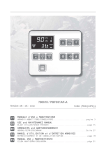
Descrizione tasti del pannello di controllo
ACCENSIONE/SPEGNIMENTO
SCHEDA DI CONTROLLO
AVVIO/ARRESTO DI UN CICLO
DI ABBATTIMENTO
Descrizione del display e dei simboli
DISPLAY 1
DISPLAY 3
DISPLAY 2
UP incrementa, durante l’abbattimento/congelamento
visualizza per alcuni secondi il tempo trascorso da inizio ciclo.
DOWN decrementa, durante l’abbattimento/congelamento
visualizza per alcuni secondi il tempo trascorso da inizio ciclo.
+3°C ABBATTIMENTO SOFT
–18°C CONGELAMENTO SOFT
+3°C ABBATTIMENTO HARD
–18°C CONGELAMENTO HARD
DISPLAY 1
Visualizzazione della temperatura dello spillone o del tempo.
DISPLAY 2
Visualizzazione della temperatura della camera.
DISPLAY 3
Visualizzazione della fase di lavoro in corso (1-3)/Nr.
Spillone inserito al cuore.
Temperatura cella.
Riscaldamento spillone attivo.
Ciclo di abbattimento/congelamento a spillone.
PROGRAMMA
selezione e memorizzazione
RICHIAMO ALLARMI HACCP
riporta data, durata, tipo, temperatura, max raggiunta
Ciclo di abbattimento/congelamento a tempo.
Sterilizzazione in corso.
Funzione ciclo abbattimento selezionato (+3°C).
STERILIZZAZIONE
Funzione ciclo di congelamento selezionato (-18°C).
RISCALDAMENTO SONDA SPILLONE
Fase hard selezionata.
per estrazione sonda spillone per programmi di congelamento
Abbattimento in corso (lampeggiante ritardo
compressore attivo).
VISUALIZZA SENSORI SONDA SPILLONE
(SONDA MULTIPUNTO - optional)
Fase conservazione in corso.
DEFROST
Macchina in stop.
avvio, sbrinamento con apparecchiatura in STOP, temperatura
sonda evaporatore premuto per 3 sec. in abb.to/cong.to
Allarme HACCP
IT - 8
AVVERTENZE GENERALI
Per un corretto uso della sonda spillone:
- evitare urti violenti, possono compromettere il corretto funzionamento della sonda.
- sterilizzare lo spillone prima di ogni utilizzo.
- lo spessore massimo consigliato del prodotto è di 45mm.
- una buona pulizia dello spillone determina una buona resa.
SONDA PUNTO SINGOLO
PER INSERIRE LA SONDA
- inserire la sonda con la punta
il più vicino possibile
al cuore del prodotto.
- inserire solo la parte lucida.
H
45mm
SONDA MULTI-PUNTO (optional)
H
45mm
PER ESTRARRE LA SONDA
- riscaldare la sonda (tasto
) vedi 7.3.5
- ruotare su se stessa
- estrarla senza inclinare lo spillone
7.2 PROGRAMMAZIONE OROLOGIO PER HACCP
A macchina spenta premendo contemporaneamente per un tempo prolungato i tasti (+3°C)
e
è possibile accedere alla modifica dell’orologio.
Sul DISPLAY 1 viene visualizzata l’ultima cifra dell’anno.
Sul DISPLAY 2 viene visualizzato la scritta “yy” .
Premendo il tasto
anno
Con il tasto
o
mese
è possibile modificare, rispettivamente:
giorno
ora
minuti
si conferma il valore immesso e si passa al successivo.
L’uscita dal menù orologio avviene automaticamente dopo 60 sec. oppure premendo il tasto +3°C
7.3 CICLI DI FUNZIONAMENTO
7.3.0. ACCENSIONE
(Fig.1)
Con la pressione del tasto
si ha l’accensione della scheda.
Sul DISPLAY 1 (Fig.1) non compare nessuna selezione.
Sul DISPLAY 2 viene visualizzata la temperatura della cella.
.
9 - IT
7.3.1. CICLO DI ABBATTIMENTO +3°C SOFT O HARD E CONGELAMENTO –18°C SOFT O HARD A
TEMPO
FASE DI ABBATTIMENTO/CONGELAMENTO
Per selezionare il ciclo di abbattimento +3°C soft premere il tasto
premere il tasto
, per quello +3°C hard
.
Per selezionare il ciclo di congelamento –18°C soft premere il tasto
, per quello –18°C hard
Premere il tasto
.
Il DISPLAY 1 visualizza il tempo totale previsto per l’abbattimento/congelamento (Fig.2).
Il DISPLAY 2 visualizza la temperatura cella.
(Fig.2)
Sono accesi i simboli del tempo
soft
o hard
, del tipo di abbattimento soft
della temperatura
e
o hard
o congelamento
.
Premendo il tasto
o
è possibile modificare la durata del ciclo.
N.B. È possibile impostare una durata: sia maggiore che minore di 90 min. per ciclo di abbattimento o
240 min. per ciclo di congelamento.
Limite massimo: 120 min. per il ciclo +3°C.
Limite massimo: 300 min. per il ciclo -18°C.
Premere il tasto
(Fig.3)
per avviare il ciclo.
Premendo il tasto
(Fig.3) si visualizza temporaneamente la temperatura rilevata dalla sonda
spillone (se infilzata sul prodotto mostra la temperatura della stesso).
Al termine del ciclo la macchina passa in fase di conservazione in automatico, vedi 7.3.5.
Premendo il tasto
si visualizza la durata del ciclo abbat./congel. appena concluso.
+3 SOFT
+3 HARD
-18 SOFT
-18 HARD
IT - 10
7.3.2. CICLO DI ABBATTIMENTO+3°C SOFT O HARD E CONGELAMENTO –18°C SOFT O HARD
AUTOMATICO A SPILLONE
FASE DI ABBATTIMENTO/CONGELAMENTO
(Fig.4)
Per selezionare il ciclo di abbattimento +3°C Soft premere
, per quello +3°C Hard il tasto
Per selezionare il ciclo di congelamento –18°C Soft premere
, per quello –18°C Hard il tasto
Premere il tasto
.
Il DISPLAY 1 visualizza la temperatura dello spillone.
Il DISPLAY 2 visualizza la temperatura della cella.
Sono accesi i simboli dello spillone
o
, della temperatura
e lo
, del tipo di abbattimento
oppure
.
Per avviare il ciclo selezionato premere il tasto
(Fig.5)
o
, si accende il simbolo
abbattimento (Fig.5).
Se non è stata raggiunta la temperatura al cuore entro il tempo prefissato, si attiva l’allarme
time out.
La fase di abbattimento continua ma i simboli
e HACCP lampeggiano, l’allarme viene
memorizzato nello storico HACCP. Sul DISPLAY 1 lampeggia la scritta AL5 (Fig.6).
L’allarme rientra automaticamente al passaggio in conservazione, rimanendo accesoil simbolo
Premendo in qualsiasi momento il tasto
(Fig.6)
, si visualizza il tempo trascorso dall’inizio dell’abbattimento.
si
Se presenta la sonda multipunto o più sonde, premendo per un tempo prolungato il tasto
visualizza in successione la temperatura dei 4 sensori sul DISPLAY 2, ed il numero corrispondente del
sensore nel DISPLAY 3.
Il sensore non riconosciuto infilzato verrà visualizzato nel DISPLAY 3 con simbolo
.
Al termine del ciclo la macchina passa in fase di conservazione in automatico, vedi 7.3.5.
Premento il tasto
si visualizza la durata del ciclo abbat./congel. appena concluso.
+3 SOFT
+3 HARD
-18 SOFT
-18 HARD
11 - IT
7.3.3. CICLO DI ABBATTIMENTO O CONGELAMENTO CON 2 - 3 - 4 SONDE SPILLONE STANDARD
E’ possibile eseguire questo ciclo con più sonde spillone standard a singolo punto di misura.
Selezionare il ciclo desiderato es.:
Premere
(Fig.7)
(Fig.8)
(Fig.9)
o
(+3°C) oppure
o
(-18°C).
.
Premere il tasto
per avviare il ciclo.
Quando la temperatura di una sonda raggiunge il valore impostato rispetto al ciclo prescelto di abbattimento/congelamento, viene segnalato con il suono di un buzzer (optional), sul DISPLAY 3
lampeggia il numero della sonda spillone relativo (Fig.7); se nel frattempo le altre sonde raggiungono
la temperatura al cuore, la segnalazione rimane in coda.
Le segnalazioni terminano ed il buzzer (optional) si spegne solo quando viene aperta la porta.
Alla chiusura della porta, quando altre sonde raggiungendo la temperatura al cuore, ricomicia una
nuova segnalazione sul DISPLAY 3 (Fig.8) che indica il numero della sonda con il prodotto abbattuto/
congelato.
Se l’abbattimento non si è concluso entro il tempo prestabilito, si attiva il buzzer (optional) per un
minuto che può essere spento premendo un tasto qualsiasi.
La fase di abbattimento continua ma i simboli orologio e HACCP lampeggiano, l’allarme viene
memorizzato nello storico HACCP. Sul DISPLAY 1 lampeggia la scritta AL5 (Fig.9).
L’allarme rientra automaticamente al passaggio in conservazione, rimanendo acceso il simbolo HACCP.
Il passaggio della fase di abbattimento a quella di conservazione, avviene solo quando tutte le sonde
spillone hanno raggiunto la temperatura al cuore desiderata, in base al ciclo prescelto.
Al termine del ciclo la macchina passa in fase di conservazione in automatico, vedi 7.3.5.
Premendo il tasto
si visualizza la durata del ciclo abbat./congel. appena concluso.
7.3.4. CICLI DI ABBATTIMENTO/CONGELAMENTO PERSONALIZZATI
,
E’ possibile modificare il ciclo di abbattimento/congelamento:
- a tempo
,
- a spillone
,
personalizzandoli secondo la proprio esigenza.
Il ciclo di abbattimento/congelamento è suddiviso in 3 fasi, caratterizzate ognuna da quattro set, dei quali
possibile modificare i seguenti valori:
PER MODIFICARE I DATI IN MODO NON PERMANENTE
(Fig.10)
premere per un tempo prolungato il relativo tasto
a- set temperatura cella fase 1/2/3/4
Il controllo visualizza (Fig.10):
DISPLAY 1 - temperatura modificabile della cella
DISPLAY 2 - nessuna segnalazione (spento)
DISPLAY 3 - il numero della fase
/
/
Lampeggia il simbolo
temperatura cella, con la pressione del tasto
decrimenta il valore del set temperatura.
(+3) /
o
(-18).
si incrementa o
b- set % velocità di rotazione ventilatore/i cella fase 1/2/3/4
Con una ulteriore pressione del tasto
compare il numero 100, si incrementa o
decrementa il valore % della velocità di rotazione del/i ventilatore/i della cella.
c- set temperatura spillone fase 1/2/3
Con una ulteriore pressione del tasto
lampeggia il simbolo dello spillone
si cambia il valore del set temperatura spillone.
d- set durata fase 1/2/3
,
IT - 12
Con una ulteriore pressione del tasto
decrementa il valore di set tempo.
lampeggia il simbolo orologio
, incrementa o
Ripetere la stessa procedura descritta per le successive fase 2 e fase 3.
La fase 4 di conservazione prevede solamente l’impostazione del set temperatura, % velocità ventole.
Per confermare le impostazioni di tutte le fasi descritte, premere per un tempo prolungato il relativo
tasto
/
/
(+3) /
(-18). Premere il tasto
per avviare il ciclo.
Al termine del ciclo la macchina passa in fase di conservazione in automatico, vedi cap. 7.3.5.
Premendo il tasto
descritto al cap. 7.3.6
si visualizza la durata del ciclo appena concluso, e si potrà memorizzare come
I nuovi set del ciclo personalizzato andranno persi alla fermata della macchina con il tasto
.
PER MODIFICARE I DATI IN MODO PERMANENTE (vedi manuale tecnico)
ABBATTIMENTO/CONGELAMENTO
CONSERVAZIONE
FASE 1
FASE 2
FASE 3
FASE 4
SET CELLA
S01
S04
S07
S10
SET VELOCITA’ VENTOLE
S50
S51
S52
S53
SET CUORE
S02
S05
S08
--
SET TEMPO
S03
S06
S09
--
7.3.5. FASE DI CONSERVAZIONE
Ad ogni fine ciclo di abbattimento/congelamento, l’apparecchiatura passa in conservazione.
Il DISPLAY 1 è spento.
Il DISPLAY 2 visualizza la temperatura della cella (Fig.11).
(Fig.11)
Il simbolo conservazione
per congelamento).
è acceso. (Temperatura conservazione +2°C per abbattimento e -20°C
Con la pressione del tasto
si visualizza la durata del ciclo di abb.to/cong.to appena concluso.
Questa fase termina premendo il tasto
, l’apparecchiatura si posiziona in stand-by.
Per facilitare l’estrazione dello spillone dal prodotto (dopo un congelamento), premere il tasto
riscaldamento sonda, si accende il simbolo
sul display.
Il riscaldamento avviene solo se la temperatura dello spillone è inferiore a -5°C.
7.3.6. MEMORIZZAZIONE DI UN PROGRAMMA DI ABBATTIMENTO/CONGELAMENTO.
Con la macchina in conservazione premendo il tasto
(Fig.12)
programma libero. Premendo il tasto
, il ciclo viene memorizzato ed il controllo si posiziona per
ripartire con un nuovo ciclo (Fig.12).
È possibile cancellare un programma memorizzato sovrapponendo ad esso un nuovo ciclo di
abbattimento/congelamento operando in questo modo: a conclusione del ciclo invece di
memorizzarlo sul primo programma libero selezionato automaticamente dal sistema, premendo
il tasto
programma
(Fig.13)
il DISPLAY 1 visualizza il numero del primo
o
e posizionarsi sul numero di programma da cancellare e premere il tasto
. Se sul DISPLAY 2 (Fig.13) a fianco del numero compaiono i simboli
significa che non c’è nessun programma memorizzato.
13 - IT
7.3.7. RICHIAMO PROGRAMMA ABBATTIMENTO/CONGELAMENTO MEMORIZZATO
Per selezionare un programma di abbattimento/congelamento memorizzato premere il tasto
premendo il tasto
(Fig.14)
o
si visualizzano in sequenza i programmi memorizzati;
premere il tasto
per avviare il programma di abbattimento/congelamento scelto.
Se sul DISPLAY 2 (Fig.14) compaiono i simboli
significa che non c’è nessun
programma memorizzato
7.4. SBRINAMENTO
Lo sbrinamento avviene se la temperatura della cella è inferiore al parametro P57 (vedi manuale tecnico).
Per avviare un ciclo di sbrinamento premere il tasto
(Fig.15)
per un tempo prolungato con
apparecchitura in
e PORTA APERTA, sul DISPLAY 1 compare la scritta
DISPLAY 2 la temperatura cella (Fig.15).
e sul
7.5. STERILIZZAZIONE (optional)
La sterilizzazione può iniziare solo se la temperatura è superiore la parametro P26 (vedi manuale tecnico).
Il ciclo viene attivato con apparecchiatura in stand-by premendo il tasto
(Fig.16)
, premendo
nuovamente il tasto il ciclo termina. Il simbolo
acceso sul dispaly determina che la fase
di sterilizzazione è in atto, il DISPLAY 1 visualizza il tempo mancante alla fine del processo.
L’apertura della porta o un blackout, interrompono la sterilizzazione (Fig.16).
7.6. STAMPANTE (optional)
Se presente la stampante, per ogni ciclo di abbattimento viene trascritta: data, ora, il tipo di ciclo, il
tempo trascorso da inizio ciclo e la temperatura cella e cuore campionata ogni 10 minuti.
Per campionamenti inferiori o superiori a 10 minuti, cambiare il parametro P44 (vedi manuale tecnico).
Con il parametro P86 (vedi manuale tecnico) è possibile cambiare la lingua della stampante.
****HELLO****
03/03/2007
10:15
+3°C HARD
Time
Ti
00:00 25
00:10 8
SP1 SP2 SP3 SP4
54
45
52
44
51
42
49
40
Time = tempo trascorso
Ti = temperatura CELLA
SP1 = sensore 1 sonda spillone multipunto (optional)
SP2 = sensore 2 sonda spillone multipunto (optional)
SP3 = sensore 3 sonda spillone multipunto (optional)
SP4 = sensore 4 sonda spillone multipunto (optional)
7.7. ALLARMI/ERRORI
7.7.0. ALLARME MANCANZA DI COMUNICAZIONE TRA TASTIERA E BASE
===> CONTATTARE ASSISTENZA TECNICA
Verificare collegamenti, accendere e spegnere l’apparecchiatura scollegando l’alimentazione.
7.7.1. ALLARME ALTA TEMPERATURA
Durante la fase di conservazione positiva (negativa), interviene l’allarme quando la temperatura cella
supera i valori impostati.
Sul DISPLAY 1 lampeggia la scritta di allarme AL1.
Il buzzer (oprional) suona, ma può essere tacitato premendo un tasto
Quando la temperatura scende sotto la soglia di allarme, esso rientra automaticamente.
7.7.2. ALLARME BASSA TEMPERATURA
Durante la fase di conservazione positiva (negativa), interviene l’allarme quando la temperatura cella
supera i valori impostati.
Sul DISPLAY 1 lampeggia la scritta di allarme AL2.
Il buzzer (oprional) suona, ma può essere tacitato premendo un tasto.
IT - 14
7.7.3. ALLARME PORTA APERTA
Dopo due minuti di porta aperta a ciclo avviato di abbattimento/congelamento il compressore si ferma
e sul DISPLAY 1 lampeggia la scritta di AL3.
7.7.4. ALLARME GENERICO ===> CONTATTARE ASSISTENZA TECNICA
Quando interviene l’allarme AL4 i cicli di abbattimento in corso terminano immediatamente.
7.7.5. ALLARME TIME OUT
Se la fase di abbattimento o congelamento in corso non terminano nel tempo prestabilito il
DISPLAY 1 lampeggia AL5.
7.7.6. ALLARME BLACKOUT
Quando avviene un blackout durante un ciclo di abbattimento, allo spegnimento la macchina ricorda il
ciclo che stava eseguendo e la fase in cui si trovava.
Nei cicli a spillone ricorda inoltre quali sensori erano inseriti.
La tolleranza dei tempi di abbattimento è 10 minuti.
Il buzzer (oprional) suona, ma può essere tacitato premendo un tasto, premendo nuovamente un
tasto la segnalazione sparisce.
7.7.7. ALLARME SONDA CELLA ===> CONTATTARE ASSISTENZA TECNICA
La sonda cella misura la temperatura della cella e viene visualizzata sul DISPLAY 2.
Un guasto della sonda provoca un allarme, si attiva il buzzer (optional) e sul display lampeggia la scritta
di errore ER1.
Il buzzer (oprional) suona, ma può essere spento premendo un tasto, al termine del guasto l’allarme
rientra automaticamente.
- Con la sonda cella guasta è tuttavia possibile iniziare o proseguire un programma di abbattimento
a tempo.
- Un programma di abbattimento a temperatura non ancora iniziato commuta a tempo allo start.
- Un programma di abbattimento a temperatura in corso, se la sonda spillone non è inserita si commuta
a tempo; il controllo del compressore viene determinato dalla sonda spillone invece che dalla sonda cella.
- Un programma di abbattimento a temperatura in corso con la sonda spillone inserita, accende e
spegne il compressore, in base ai tempi memorizzati in precedenza in abbattimento o in coservazione.
7.7.8. ALLARME SONDA SPILLONE ===> CONTATTARE ASSISTENZA TECNICA
- quatto sensori contemporaneamente La sonda spillone è utilizzata per i cicli di abbattimento a spillone.
Un guasto della sonda spillone provoca un allarme solo se è in corso un ciclo di abbattimento con
controllo temperatura al cuore; in tal caso il ciclo automaticamente si commuta a tempo e si attiva il
buzzer (oprional) e sul DISPLAY 1 lampeggia la scritta di allarme ER2.
Il buzzer (oprional) suona, ma può essere spento premendo un tasto e la scritta di allarme scompare
premendo un tasto.
ALLARME SONDA SPILLONE:
1
2
3
4
7.7.9. ALLARME SONDA EVAPORATORE ===> CONTATTARE ASSISTENZA TECNICA
La sonda permette di terminare uno sbrinamento per temperatura.
Per vedere la temperatura dell’evaporatore premere e rilasciare il tasto
, viene visualizzata sul
DISPLAY 2.
Un guasto della sonda provoca un allarme guasto della sonda evaporatore e si attiva il buzzer (oprional)
e sul DISPLAY 1 lampeggia la scritta di allarme ER7.
Il buzzer (oprional) suona, ma può essere spento premendo un tasto, al termine del guasto l’allarme
rientra automaticamente. Con la sonda in allarme lo sbrinamento termina a tempo.
15 - IT
7.8. HACCP
Quando il Simbolo HACCP lampeggia vuoi dire che si è verificato un nuovo Allarme HACCP.
Per visualizzare l’allarme bisogna entrare nella visualizzazione degli allarmi HACCP premendo il tasto
HACCP
.
Sul DISPLAY 1 viene visualizzato il tipo di Allarme ‘AL1’
Sul DISPLAY 2 viene visualizzato ‘AL’
Sul DISPLAY 3 viene visualizzata la posizione dell’allarme ‘4’
Il Simbolo HACCP è acceso.
Se l’allarme è di Alta/Bassa Temperatura il Simbolo Termometro
è acceso.
Se l’allarme è di TimeOut o BlackOut, il Simbolo Orologio
è acceso.
Questa rappresentazione indica che l’ultimo allarme è di Alta Temperatura e 4 è la posizione in memoria dell’allarme; possono essere memorizzati 10 allarmi HACCP e la posizione va da 0 a 9.
Con i Tasti UP e DOWN si possono scorrere gli allarmi in memoria.
Premendo il Tasto
si accede alla visualizzazione della data di inizio allarme:
Sul DISPLAY 1 viene visualizzato il giorno di inizio Allarme ‘15’
Sul DISPLAY 2 viene visualizzato ‘dd’
Sul DISPLAY 3 rimane visualizzato il numero dell’allarme ‘4’
Con la pressione del tasto
o
si possono vedere la data e l’ora:
‘15’
‘d d’
‘45’
‘m m’
‘127’
’t t’
‘10’
‘M M’
‘05’
‘y y’
‘14’
‘h h‘
dove ‘tt’ indica la durata in minuti dell’allarme.
Se l’allarme è di Bassa o Alta Temperatura la visualizzazione successiva la data è la temperatura minima o massima raggiunta:
Sul DISPLAY 1 viene visualizzata la Temperatura massima ‘- 10’
Sul DISPLAY 2 viene visualizzato ‘H t’ o ‘L t’
Premendo il tasto
zare gli allarmi.
si esce dalla visualizzazione della data di inizio allarme e si tornano a visualiz-
Gli allarmi HACCP memorizzati sono:
- Allarme di Alta Temperatura in Conservazione
- Allarme di TimeOut ciclo di Abbattimento
- Allarme di Bassa Temperatura in Conservazione
- Allarme di BlackOut
Premendo il Tasto
si esce dal menu HACCP.
Una volta visualizzato l’Allarme HACCP, il Simbolo
ad un nuovo allarme HACCP.
non lampeggia più e rimane spento fino
7.8.1 RESET ALLARMI HACCP
E’ possibile cancellare la memoria degli allarmi HACCP:
- Spegnere la scheda col tasto
- Premere a lungo contemporaneamente i tasti
- Sul display compare la scritta ‘RES HACCP’ .
e
- Premere a lungo contemporaneamente i tasti
e
(-18°C)
17 - GB
TABLE OF CONTENTS
1. PRESCRIPTIONS AND GENERAL INSTRUCTIONS
1.1. Testing
1.2. Guarantee
1.3. Introduction
1.4. Prerequisites supplied by the customer
1.5. Instructions on requests for intervention
1.6. Instructions for spare parts
2. TECHNICAL DATA
2.1. Noise level
2.2. Materials and fluids used
3. OPERATION
3.1. Applications, purpose, foreseen and unforeseen
use, authorised use
3.2. Dangerous areas
3.3. Safety devices
4. MORDINARY AND PROGRAMMED MAINTENANCE
4.1. Elementary safety standards
4.2. Instructions for emergency operations in the case
of fire
4.3. Cleaning the machine
4.4. Periodic verifications
4.5. Precautions in the case of extended periods of inactivity
4.6. Extraordinary maintenance
5. WASTE DISPOSAL AND DISMANTLING
5.1. Waste storage
5.2. Procedures relating to the macro dismantling
operations of the machine
6. INSTALLANTIO
6.1. Transport and handling of the product
6.2. Description of installation operations
6.3. Positioning
6.4. Power connection
6.5. Re-installation
7. USER INSTRUCTIONS
7.1. Control panel
7.2. Clock programming according to HACCP
7.3. Operational cycles
7.3.0. Switching on
7.3.1. Soft or hard + 3ºC blast chill cycle and
soft or hard -18ºC shock freeze with pin probe
7.3.2. Soft or hard blast chill cycle + 3ºC and
soft or hard shock freezing -18ºC with pin probe
7.3.3. Blast chill/shock freeze cycle with 2 – 3
– 4 standard pin probes
7.3.4. Blast chill or shock freeze personalize cycle
7.3.5. Conservation phase
7.3.6. Memorising a blast chill/shock freeze
programme
7.3.7. Recall of memorised blast chill/shock
freeze programme
7.4. Defrosting
7.5. Sterilisation (optional)
7.6. Printer (optional)
7.7. Alarms/errors
7.7.1. High temperature alarm
7.7.2. Low temperature alarm
7.7.3. Door open alarm
7.7.4. Pressure switch alarm
7.7.5. Time out alarm
7.7.6. Blackout alarm
7.7.7. Cabinet probe alarm
7.7.8. Pin probe alarm
7.7.9. Evaporator probe alarm
7.8. HACCP
7.8.1. HACCP alarm re-set
1. PRESCRIPTIONS AND GENERAL INSTRUCTIONS
1.1. TESTING
The product is dispatched after visual, electrical and operating tests have
been performed.
1.2. GUARANTEE
The guarantee on the machine and related parts manufactured by us is
valid for a period of 1 year from the date of invoice and consists of the
free supply of spare parts which, according to our final judgement, are
deemed to be defective.
It is the responsibility of the manufacturer to eliminate any faults and
defects on condition that the machine has been correctly used in accordance with the instructions provided in the manual.
During the guarantee period the customer will be responsible for costs
related to labour, travel or transfers, transport of the parts and any equipment to be replaced. The items replaced under guarantee remain our
property and must be returned by the customer at the customer’s expense.
1.3. INTRODUCTION
The present manual is intended to provide all the necessary information for correct installation, operation and mainenance of the machine by
qualified personnel.
Read the instructions provided carefully prior to any operation, as these
contain essential safety indications concerning the machine.
THE MANUFACTURER DOES NOT ACCEPT ANY RESPONSIBILITY FOR
UNAUTHORISED USE OF THE PRODUCT.
THE REPRODUCTION OF THIS MANUAL OR PARTS THEREOF, IS PROHIBITED.
GENERAL SAFETY INSTRUCTIONS
The manufacturer does not accept any responsibility for any operation
performed on the machine in disregard of the instructions provided in
this manual.
Before connecting the machine to the power supply, ensure
that the voltage and frequency correspond to those indicated on the
specifications plate.
Always connect the machine to an appropriate high
sensitivity differential magnetothermic switch (30 mA).
Before performing any cleaning or maintenance operation:
Disconnect the machine from the power supply by:
1) Positioning the main switch on OFF;
2) Removing the plug.
Wear gloves to perform maintenance on the motor compartment or on the evaporating unit positioned inside the machine.
Do not insert screwdrivers or other devices into the protective
units (ventilator, evaporator, etc. protections).
shoes.
Do not handle electrical parts with wet hands or without
Ensure good functioning of the compressor unit and evaporator by never obstructing the air inlets.
In the case of machines fitted with key lock, it is recommended
that the keys be kept out of reach of children.
Operation is reserved exclusively to appropriate and trained
personnel.
GB - 18
Installation, ordinary and extra-ordinary maintenance (for
example, cleaning and maintenance of the refrigerating system), must
be performed by specialised and authorised technical personnel with a
sound knowledge of the refrigeration and electrical systems.
1.4. PREREQUISITES SUPPLIED BY THE CUSTOMER
Provide a high sensitivity differential magnetothermic switch (30 mA).
Provide a wall socket of the type used in the country in which the machine is operated.
Verify that the surface on which the machine rests is level.
In the case of machines with water condenser or with equipment with
direct humidity control, provide connection to a water system.
1.5. INSTRUCTIONS ON REQUESTS FOR INTERVENTION
Often operating difficulties are a result of ordinary causes which are almost always remediable inhouse, therefore, before requesting assistance
from a technician, perform the following simple verifications:
IF THE MACHINE STOPS OPERATING:
- Check that the plug is inserted correctly in the electrical socket.
IF THE CABINET TEMPERATURE IS INSUFFICIENT:
- Verify that this is not being influenced by a heat source;
- Verify that the doors close perfectly;
- Verify that the condenser filter is not blocked;
- Verify that the ventilation grills of the control panel are not obstructed;
- Verify that the items inside the cabinet are not obstructing ventilation.
IF THE MACHINE IS NOISY:
- Verify that there is no loose contact between the machine and another object;
- Verifty that the machine is perfectly level;
- Verify that the screws (at least those visible) are tightly closed;
If the defect persists after the above verifications, request technical assistance, indicating:
- The nature of the defect;
- The code and serial number of the machine appearing on the specifications plate.
1.6. INSTRUCTIONS FOR SPARE PARTS
ORIGINAL SPARE PARTS are recommended.
The manufacturer does not accept any responsibility for the use of nonoriginal parts.
2. TECHNICAL DATA
The technical data plate is located outside on the side or at the rear, and
inside the motor compartment.
2.1. NOISE LEVEL
Leq at the noisiest point at 1 m in operating condition
Lpc at 1 m in operating conditions
< 70 dB (A)
< 130 dB (C)
TESTING ENVIRONMENT
Testing has been performed in a rectangular showroom with no sound
absorption.
Significant obstacles were absent in the area surrounding the machine.
REFERENCE REGULATIONS
Noise testing was performed in compliance with Legislative Decree 277
and in accordance with methods described in ISO 230-5, in order to obtain the data required by EEC Directive 89/392.
OPERATING CONDITIONS OF THE MACHINE
Testing was performed under the most severe condition which corresponds to the start-up phase called “PULL DOWN”.
2.2. MATERIALS AND FLUIDS USED
The materials used comply with Legislative Decree of 25 July 2005, No.
151 in enactment of Directives 2002/95/EC, 2002/96/EC and 2003/108/
EC, relating to the reduction in the use of hazardous substances in electrical and electronic equipment, as well as to waste disposal
3. OPERATION
3.1. APPLICATIONS, PURPOSE, FORESEEN AND UNFORESEEN USE, AUTHORISED USE
Our refigerators are agroindustrial machines (EC regulation No.
1935/2004), intended for foodstuffs.
The machines are designed with the appropriate equipment to guarantee
the health and safety of the user.
APPLICATION OF THE BLAST CHILLER-FREEZER:
The blast chiller-freezer is a machine which rapidly lowers the temperature of cooked or raw foods, in order to maintain unaltered the organoleptic properties (chemical-physical and nutritional) of these foods.
Cooling or freezing time, in function with the type or types of
elements present in a cooked dish (density, portions), is a variable parameter not easy to stabilise. The declared performances have been obtained with potato puree, deposited in GN1/1
H=40 steel baking trays. The thickness of the puree contained
in the trays is 25mm.
BLAST CHILL TEMPERATURE CYCLE:
This cycle enables a rapid lowering of the temperature of the cooked food
(from +90 to +3°C in 90 minutes) to avoid it remaining within the critical
temperature range of +10°C to +65°C.
The cooked and blast chilled food can be stored in the refrigerator for
up to 5 days.
SHOCK FREEZE TEMPERATURE CYCLE:
Shock freezing (from +90°C to -18°C) prevents the formation of macrocrystals of ice in the food, which would result in a loss of liquids and
vitamins.
This cycle is suitable for cooked and raw food and conserves these foodstuffs for up to 2 months and 12 months respectively.
CONSERVATION CYCLE:
At the end of every blast chill or shock freeze cycle the machine provides for a conservation cycle during which the equipment functions as
a normal refrigerator and the duration of which is to the discretion of
the user.
FOODSTUFFS STORAGE
For the best performance, the following indications should be observed:
Conservation cycle:
- Do not introduce inside the machine hot foods or uncovered liquids;
- Wrap or protect foodstuffs, in particular if they contain aromas;
- Arrange the foodstuffs inside so as not to limit air circulation, avoiding
placing on the racks papers, cartons, boards, etc. which may obstruct the
passage of air;
- Avoid as far as possible opening the door frequently or for lengthy
periods of time.
Blast chill cycle / shock freeze
- Do not open the door once the cycle has commenced and until the cycle
has terminated;
- Avoid wrapping, protecting or closing containers with lids or insulating films;
- Do not use trays or containers higher than 65mm;
- Do not stack foodstuffs;
- Use aluminium or stainless steel containers.
3.2. DANGEROUS AREAS, RISKS, HAZARDS AND UNAVOIDABLE RISKS
The refrigerator equipment has been designed and manufactured with
the appropriate devices to guarantee the health and safety of the user
and does not contain dangerous edges, sharp surfaces or protruding elements.
The stability of the machine is guaranteed even when the doors are open;
however, do not pull on the doors.
In the case of refrigerators with drawers, do not open more than one
drawer at a time and do not lean or sit on an open drawer, so as to avoid
overturning or damaging the refrigerator.
N.B.: In refrigerators with glass doors do not extract more than one
19 - GB
basket or rack at a time so as not to compromise the stability of the
refrigerator.
Gradually arrange the foodstuff starting from the bottom upwards; similarly, remove foodstuff starting from the top downwards.
THE MACHINE HAS NOT BEEN DESIGNED TO BE INSTALLED IN AN EXPLOSIVE ATMOSPHERE.
Maximum load (uniformly distributed) per basket, drawer or
rack = 40 kg
REFRIGERATOR WITH CASTERS
When moving, take care not to forcefully push the refrigerator so as avoid
overturning and damage. Note also any unevenness of the surface on
which the refrigerator is being pushed. Refrigerators fitted with casters
cannot be levelled, therefore, ensure that the surface on which they rest
is perfectly horizontal and level.
ALWAYS BLOCK THE CASTERS WITH THE STOPS PROVIDED.
DANGER CAUSED BY MOVING PARTS
The only moving part is the ventilator, which presents no risk as it is
isolated by a protection grill secured with screws (before removing this
protection, disconnect the machine from the power supply).
DANGER CAUSED BY LOW/HIGH TEMPERATURES
Adhesive labels indicating “TEMPERATURE WARNING” are located in the
proximity of areas which constitute dangers of low/high temperatures.
DANGER CAUSED BY ELECRICAL POWER
Electrical risks have been eliminated by designing the electrical system in
accordance with CEI EN 60204-1 and CEI EN 60335-1.
Adhesive labels indicate “high voltage” areas which may present electrical risks.
DANGER CAUSED BY NOISE
Leq at the noisiest point at 1 m in operating conditions
Lpc at 1 m in operating conditions
< 70dB (A)
< 130 dB(C)
OTHER RISKS
Any liquids emanating from foodstuffs or washing products are prevented
from leaking outside by a drain positioned at the bottom. During cleaning operations, remove the plug and place a collection tray under the
machine (hmax=100mm).
IT IS OF UTMOST IMPORTANCE THAT THE PLUG IS REFITTED IN
THE HOLE. IN THE CASE OF MACHINES WITH NO DRAIN, AVOID
ANY REMNANTS OF LIQUIDS BY CLEANING THOROUGHLY ON A
DAILY BASIS
3.3. SAFETY DEVICES
IT IS ABSOLUTELY PROHIBITED TO TAMPER WITH
OR REMOVE THE SAFETY DEVICES PROVIDED (PROTECTION
GRILLS, DANGER LABELS, ETC.). THE MANUFACTURER DOES
NOT ACCEPT ANY RESPONSIBILITY SHOULD THE SAID INSTRUCTIONS NOT BE OBSERVED.
Tampering with or removing the safety devices provided (protection grills,
danger labels, etc.) is expressly prohibited. The manufacturer does not
accept any responsibility should the said instructions not be observed.
4. ORDINARY AND PROGRAMMED MAINTENANCE
The information contained in this section refers to appropriate and trained
personnel in the case of ordinary maintenance; while specialised and
authorised personnel is required for extraordinary and/or programmed
maintenance.
4.1. ELEMENTARY SAFETY STANDARDS
Before performing any intervention, disconnect the plug of the machine
from the electrical power supply.
REMOVAL OF PROTECTIONS OR SAFETY DEVICES IS PROHI
BITED.
In ordinary maintenace operations, the removal of protections/saftey devices (grills, adhesive labels, etc.) is prohibited.
4.2. INSTRUCTIONS FOR EMERGENCY OPERATIONS IN
THE CASE OF FIRE
NOTE:
Do not use water in the case of fire.
Use CO2 fire extinguisher (carbonic anhydride) and cool the motor compartment area as quickly as possible.
4.3. CLEANING THE MACHINE
Before any cleaning operation, disconnect the machine from the electrical
power supply.
INITIAL INSTALLATION
Before operating, wash the interior and accessories with a little water and
neutral soap in order to remove the characteristic “new” odour. Arrange
the accessories inside the cabinet in positions most appropriate for use.
DAILY CLEANING
Carefully clean the external surfaces of the machine using a damp cloth
and following the direction of the finish.
Use neutral detergents and not substances with a chlorine and/or abrasive base.
Do not use utensils which may cause scraches and consequently the
formation of rust. Rinse with clean water and dry carefully.
Clean the interior of the cabinet with neutral detergents which do not
contain chlorine or abrasives, to avoid the formation of dirt residues. In
the case of hardened residues, use soap and water or neutral detergents,
using a wooden or plastic spatula if necessary.
After cleaning, rinse with a little water and dry carefully.
Do not wash the machine with direct water jets, as any water leakage
into electical components may affect their proper functioning.
Lower and adjoining areas of the machine must also be cleaned on a
daily basis with soap and water and not with toxic or chlorine-based
detergents.
PERIODIC CLEANING AND GENERAL MAINTENANCE
Cleaning and general maintenance operations must be carried out to
ensure the consistent performance of the machine.
The refrigerator unit (condenser) must be cleaned by specialised personnel.
Regularly clean the drain to avoid that the hole becomes blocked.
IT IS OF UTMOST IMPORTANCE THAT THE HOLE IS CLOSED ONCE
AGAIN WITH THE APPROPRIATE PLUG.
4.4. PERIODIC VERIFICATIONS
- Check that the plug is correctly inserted in the power supply.
- Check the absence of effects from heat sources.
- Check that the machine is perfectly level.
- Check that the door gasket seals perfectly.
- Check that the drain is not blocked.
- Check that the condenser battery is not covered with dust; should this
be the case, request technical assistance.
4.5. PRECAUTIONS IN THE CASE OF EXTENDED PERIODS OF INACTIVITY
If an extended period of inactivity of the machine is foreseen:
- switch the machine off by pressing the OFF button on the control panel;
- remove the plug from the power supply;
- empty the refrigerator and carefully clean it (see section on cleaning);
- leave doors ajar to ensure air circulation and avoid the formation of
mould and/or bad odours.
4.6. EXTRAORDINARY MAINTENANCE
(only by specialised personnel)
- Periodically clean condenser.
- Check door gaskets to ensure perfect sealing.
- Check that the electrical system is in order.
- Check the surround heating elements (using an amperometric clamp).
IN THE CASE OF REPAIRS OR REPLACEMENT OF PARTS, ALWAYS
PROVIDE THE CODE AND SERIAL NUMBER OF THE MACHINE,
VISIBLE ON THE SPECIFICATIONS PLATE.
GB - 20
5. WASTE DISPOSAL AND DISMANTLING
5.1. WASTE STORAGE
A provisional storage of special waste is permitted, with a view to sposal
by waste treatment and/or final storage.
In all cases, environmental laws applicable in the country of the user
must be observed.
5.2. PROCEDURES RELATING TO THE MACRO
DISMANTLING OPERATIONS OF THE MACHINE
Although legislation differs in various countries, prescriptions established
by law and responsibile bodies in the countries in which the dismantling
takes place, must be observed.
Generally, the refrigerator must be returned to the seller or to specialised
collecting/dismantling centres.
Dismantle the refrigerator, grouping the components according to their
chemical nature and remembering that the compressor contains lubrica
ting oil and liquid refrigerant which can be recovered and re-used, and
that refrigerator components are special wastes comparable to urban
waste.
DISMANTLING OPERATIONS MUST BE PERFORMED BY QUALIFIED PERSONNEL.
6. INSTALLATION
(only by specialised technical personnel)
6.1. TRANSPORT AND HANDLING OF THE PRODUCT
The machine must be transported with the appropriate handling equipment and never manually.
If lifting systems are used, such as a forklift or transpallet, take particular
care that the load is balanced.
Normally the packaging is expandable polystyrene on wood pallets, secured to the bottom of the machine for greater safety during transport
and handling.
Warnings are printed onto the packaging, representing the instructions
to be observed to ensure that no damage is caused during loading and
unloading operations, transport or handling.
WARNINGS PRINTED ON OUR PACKAGING (UNI 6720-70):
TALL LOAD
FRAGILE
KEEP DRY
The user must dispose of the packaging in accorance with the laws in
the applicable country.
STACKING LIMITS
When storing or transporting the machine, the maximum stacking limit is
two machines, unless otherwise indicated with an appropriate adhesive
label.
SINCE THE CENTRE OF GRAVITY OF THE MACHINE DOES NOT CORRESPOND TO ITS GEOMETRIC CENTRE, BE AWARE OF INCLINATIONS
DURING HANDLING.
6.2. DESCRIPTION OF INSTALLATION OPERATIONS
After removing the packaging from the machine, it is advisable to verify
the integrity of the machine and the absence of damage due to transport. Any damage must be communicated to the carrier immediately.
Damaged machines cannot be returned to the manufacturer under any
circumstances unless notice is given and prior written authorisation is
received.
DURING HANDLING DO NOT PUSH OR DRAG THE MACHINE
SO AS TO AVOID IT FROM OVERTURNING OR ANY OF ITS PARTS BEING
DAMAGED (E.G. STABILITY FEET).
NEVER LEAN THE MACHINE ON THE SIDE OF THE DOOR.
6.3. POSITIONING
Position the machine in a well-aerated place and far from heat sources.
Observe minimum gaps for operating functions, aeration and maintenance.
MACHINE WITH CASTERS
A machine with casters cannot be levelled, therefore, ensure that the
surface on which it rests is perfectly horizontal and level.
AFTER HAVING POSITIONED THE MACHINE, ALWAYS BLOCK
THE CASTERS.
DURING HANDLING DO NOT PUSH FORCEFULLY OR DRAG
THE MACHINE TO AVOID IT OVERTURNING OR BEING DAMAGED. PAY
PARTICULAR ATTENTION TO UNEVENNESS OF SURFACES. NEVER LEAN
THE MACHINE ON THE SIDE OF THE DOOR.
THE MACHINE HAS NOT BEEN DESIGNED TO BE INSTALLED
IN EXPLOSIVE ENVIRONMENTS.
6.4. POWER CONNECTION
Before connecting the machine to the power supply, ensure that the voltage and frequency correspond with those indicated on the specifications
plate.
A variation of +/-10% of the normal voltage is permitted.
It is of utmost importance that the machine is connected to an efficient
earth connection.
DO NOT USE PLUGS WITH NO EARTH. THE WALL SOCKET
MUST COMPLY WITH REGULATIONS VALID IN THE APPLICABLE COUNTRY.
EARTHING THE MACHINE IS A MANDITORY SAFETY MEASURE
BY LAW
In order to protect the machine from any electrical overload or shortcircuit, connection to the power supply is through a high sensitivity differential magnetothermic switch (30 mA) with manual re-set and with
sufficient power.
Specifications of this protective device are as follows:
Imax = 2,3 In (nominal current)
Icc (short-circuit current) = 4500 A with power supply 230v/1~/50Hz.
Icc (short-circuit current) = 6000 A with power supply 400v/3~/50Hz.
6.5. RE-INSTALLATION
If a re-installation is necessary, proceed as follows:
1) Postion the power supply switch on OFF;
2) Disconnect the plug from the power supply and wind up the cable;
3) Remove all foodstuff from the interior of the cabinet and clean the
cabinet and accessories thoroughly;
4) Re-pack the machine, taking care to re-position the protective polystyrene and secure the wooden base, in order to prevent damage during
transport;
5) Proceed as described previously for the new positioning and connection (SEE DESCRIPTION OF INSTALLATION OPERATIONS).
21 - GB
7. USER INSTRUCTIONS
7.1. CONTROL PANEL
Description of control panel
ELECTRONIC CONTROL BOARD ‘ON’
START/STOP BLAST CHILL CYCLE
Description of the display and symbols.
DISPLAY 1
DISPLAY 3
DISPLAY 2
UP increases, during blast chilling/shock freezing displays
for a few seconds the time elapsed from start of cycle.
DOWN
decreases, during blast chilling/shock freezing
displays for a few seconds the time elapsed from start of cycle.
+3°C SOFT BLAST CHILL
–18°C SOFT SHOCK FREEZE
DISPLAY 1
Displays pin probe temperature or time.
DISPLAY 2
Displays temperature of the cabinet.
DISPLAY 3
Displays the operational phase in progress (1-3)/No. of
pin probe inserted in core.
Cabinet temperature.
HARD BLAST CHILL +3°C
Heating active pin probe.
Blast chill/shock freeze cycle with pin probe.
HARD SHOCK FREEZE -18°C
PROGRAMME
selection and memorising
HACCP ALARM RECALL
Blast chill/shock freeze cycle with timer.
Sterilisation in progress.
Blast chill cycle function selected (+3ºC).
reports date, duration, type, temperature, max. range
Shock freeze cycle function selected (-18ºC).
STERILISATION
Hard phase selected.
PIN PROBE HEATING
Blast chill in progress (flashing active compressor
delay).
for pin probe extraction in shock freezing programmes
PIN PROBE SENSOR DISPLAY
(PROBE MULTI-POINT - optional)
DEFROST
Start/stop defrosting, evaporator probe temperature
Conservation phase in progress.
Machine in Stop mode.
HACCP HACCP alarm.
GB - 22
GENERAL RECOMMENDATIONS
For correct use of the spike probe:
- avoid violent blows, they can jeopardise the correct functioning of the probe.
- sterilise the spike before use.
- the maximum recommended thickness of the product is 45mm.
- cleanliness of the spike determines good performance.
SINGLE POINT-PROBE
TO INSERT THE PROBE
- insert the probe with the point
as near as possible to the heart of the product.
- to only insert the part polishes.
H
45mm
MULTI POINT-PROBE (optional)
H
45mm
TO EXTRACT THE PROBE
- heat the probe
see 7.3.5.
- turn it
- extract it without tilting the spike
7.2 CLOCK PROGRAMMING ACCORDING TO HACCP
When machine is off, press simultaneously for five seconds buttons
( +3°C) and
.
DISPLAY1 indicates the last figure of the year
DISPLAY2 indicates the letters “YY” “MM” “dd” “hh” “mm”.
By pressing the
year
By pressing the
or
in a clockwise or anti-clockwise direction to change:
mounth
day
hour
minutes
to confirm the value entered and pass on to the next value.
Exit from the clock menu occurs automatically after 60 seconds or by pressing the
7.3 OPERATIONAL CYCLES
7.3.0. SWITCHING ON
By pressing the
button the board switches on.
No selection is visible in DISPLAY 1 (Fig.1).
DISPLAY 2 indicates the cabinet temperature.
(Fig.1)
button.
23 - GB
7.3.1. +3ºC SOFT OR HARD BLAST CHILL CYCLE AND -18ºC SOFT OR HARD SHOCK FREEZING
WITH TIMER
HARD BLAST/SHOCK FREEZE PHASE
Press the
button to select the +3ºC soft blast chill cycle and the
+3ºC hard cycle.
button for the
Press the
button to select the -18ºC soft blast chill cycle and the
-18ºC hard cycle.
button for the
DISPLAY 1: indicates the total time foreseen for blast chilling/shock freezing (Fig.2).
DISPLAY 2: indicates the cabinet temperature.
(Fig.2)
The following symbols light up: time
freezing soft
or hard
, type of blast chilling soft
temperature
and
or hard
shock
.
to change the cycle duration.
or
By pressing the
N.B.: It is possible to set a duration either shorter or longer that 90 min. for blast chill cycles or 240
min. for shock freeze cycles.
Maximum limit: 120 min. for a +3°C cycle.
Maximum limit: 300 min. for a -18°C cycle.
Press the
(Fig.3)
button to start the cycle.
By pressing button
(Fig.3) the temperature read by the pin probe is temporarily displayed (if
inserted into the product, it will show the temperature of this product). At termination of the blast
chill/shock freeze cycle the machine automatically progresses to conservation.
At the end of the cycle the machine moves into conservation phase automatically, see ch. 7.3.5.
Once the cycle is activated, By pressing the
beginning of the cycle.
it is possible to visualize the elapsed time from the
+3 SOFT
+3 HARD
-18 SOFT
-18 HARD
GB - 24
7.3.2. AUTOMATIC + 3ºC SOFT OR HARD BLAST CHILL CYCLE AND -18ºC SOFT OR HARD SHOCK
FREEZING WITH PIN PROBE
BLAST CHILL/SHOCK FREEZE PHASE
Press the
hard cycle.
, button to select the +3ºC soft blast chill cycle and the
Press the
hard cycle.
, button to select the -18°C soft blast chill cycle and the
Press the
botton.
button for the +3ºC
button for the -18ºC
DISPLAY 1 the pin probe temperature.
DISPLAY 2 indicates the cabinet temperature. (Fig.4).
(Fig.4)
The following symbols light up: pin probe
and
, temperature
and
, type of blast chill either
and
or
.
(Fig.5)
To start the selected cycle press the
, button and the blast chill symbo
lights up (Fig.5).
If the core temperature has not been reached within the time determined, the time out alarm is activated.
(Fig.6)
and HACCP and HACCP symbols flash and the alarm is
The blast chill phase continues but the
memorised in the HACCP archives. The code AL5 flashes on DISPLAY 1 (Fig.6).
The alarm is automatically cancelled when passing to the conservation phase and the symbol remains
on HACCP .
By pressing the
, at any time during the cycle in progress, the time from the start of
blast chilling is indicated.
Press for extended time, if present the multi-point, the multi-point button
to display in
succession the temperature of the 4 sensors on DISPLAY 2 and the corresponding number of the
sensor on DISPLAY 3. The undetected inserted sensor is displayed in DISPLAY 3 with the symbol
At the end of the cycle the machine moves into conservation phase automatically, see ch. 7.3.5.
Once the cycle is activated, By pressing the
beginning of the cycle.
it is possible to visualize the elapsed time from the
+3 SOFT
+3 HARD
-18 SOFT
-18 HARD
.
25 - GB
7.3.3. BLAST CHILL OR SHOCK FREEZE CYCLE WITH 2 – 3 – 4 STANDARD PIN PROBES
This cycle can be run with several standard single-point pin probes.
Select the cycle desired, e.g.:
ton to start the cycle.
(Fig.7)
(Fig.8)
(Fig.9)
or
(+3°C) or
or
(-18°C) then press the
but
Press the
botton.
When the temperature of a probe reaches the value entered for the blast chill/shock freezer cycle
selected, this is signalled with a buzzer (optional) , and DISPLAY 3 flashes the number of the relevant
pin probe (Fig.7).
If in the meantime the other probes reach core temperature, the signal is placed in a queue.
The signals terminate and the buzzer (optional) switches off only when the door is opened.
Once the door is closed and the other probes reach core temperature, a new signal appears on
DISPLAY 3 (Fig.8) which indicates the number of the probe of the blast chilled/shock frozen product.
If blast chilling is not complete within the determined time, the buzzer (optional) activates for one
minute and can be switched off by pressing any button.
The blast chill phase continues but the clock and HACCP symbols flash and the alarm is memorised in
the HACCP records. The code AL5 flashes on DISPLAY 1. (Fig.9).
The alarm cancels automatically when passing to the conservation phase and the HACCP symbol
remains on.
Progress from the blast chill phase to the conservation phase occurs only when all the pin probes
have reached the desired core temperature on the basis of the cycle selected.
Upon termination of the cycle the machine automatically proceeds to the conservation phase.
At the end of the cycle the machine moves into conservation phase automatically, see ch. 7.3.5.
Once the cycle is activated, By pressing the
beginning of the cycle.
it is possible to visualize the elapsed time from the
7.3.4. BLAST CHILL OR SHOCK FREEZE PERSONALIZE CYCLE
,
It is possible to modify the breakdown/freezing cycle:
timed
probe
,
personalising them as required.
The breakdown or freezing cycle is divided into three phases where it is possible to modify the following
values:
IN ORDER TO MODIFY THE DATA IN NOT PERMANENT WAY
Press the relevant key
/
/
(+3) /
(-18) for extended time.
a- set cabinet temperature phase 1/2/3/4
Control displays (Fig.10):
SCREEN 1- modifiable cell temperature
SCREEN 2 - no signal (off)
SCREEN 3 – the number of the phase
(Fig.10)
The cell temperature symbol
is increased or decreased.
flashes, by pressing the
or
the value of the set temperature
b- set % rotation speed of cabinet fan/s phase 1/2/3/4
With a further pressing the
number 100 appears. the value of the set % value of the rotation
speed of the fan/s of the cell increases or decreases.
c- set pin temperature phase 1/2/3
With a further pressing the
changes.
the pin symbol flashes
, the value of the set pin temperature
GB - 26
d- set duration phase 1/2/3
With a further pressing the
the clock
symbol flashes, rotating the knob the set time
value increases or decreases.
Repeat the same procedure described for the later phases 2 and 3.
Phase 4 of conservation only involves setting the set temperature. To confirm the settings of all the
/
phases described, press the relevant key
Press the
/
(+3) /
(-18) for extended time.
button to start the cycle.
At the end of the cycle the machine moves into conservation phase automatically, see ch. 7.3.5.
By pressing the
displays the duration of the cycle just finished, and it can be stored as described at ch. 7.3.6.
The new sets of the personalised cycle will be lost when the machine is stopped with key
.
IN ORDER TO MODIFY THE DATA IN PERMANENT WAY (see tecincal manual)
BLAST CHILL OR SHOCK FREEZE
PHASE 1
PHASE 2
CONSERVATION
PHASE 3
PHASE 4
SET CABINET
S01
S04
S07
S10
SET FAN SPEED
S50
S51
S52
S53
SET CORE
S02
S05
S08
--
SET TIME
S03
S06
S09
--
7.3.5. CONSERVATION PHASE
The machine proceeds to conservation phase when the last pin probe has reached core temperature
at the end of the cycle. DISPLAY 2 indicates the cabinet temperature (Fig.11).
(Fig.11)
The conservation symbol
light up. By pressing the
to view the time elapsed from
the beginning of the conservation phase. This phase is terminated by pressing the
, button.
The machine sets itself on Stand-by and the user is asked whether the programme is to be memorised or the button must be pressed once more. Press the pin probe heating button
extraction of the probe from the product (after shock freezing).
to facilitate
The
symbol lights up on the display.
Pin probe heating takes place only if the temperature of the probe is less than -5ºC.
7.3.6. MEMORISING A BLAST CHILL/SHOCK FREEZE PROGRAMME.
Press the
(Fig.12)
button when the machine is in conservation mode. DISPLAY 1 indicates the number
of the first free programme. When the
, button is pressed, the cycle is memorised and the control positions itself to re-start with a new cycle (Fig.12).
It is possible to cancel a memorised programme by overwriting it with a new blast chill/shock freeze
cycle as follows: instead of memorising a completed cycle on the first free programme automatically
selected by the system, pressing the
(Fig.13)
or
position it on the number of the programme to be
cancelled and press the programme button
.
If symbols
appear on DISPLAY 2 (Fig.13) next to the number, it means that there are no
memorised programmes.
27 - GB
7.3.7. RECALL OF MEMORISED BLAST CHILL/SHOCK FREEZE PROGRAMME
To select a blast chill/shock freeze programme press button
(Fig.14)
, by pressing the
or
the
memorised programmes are displayed in sequence (Fig.14). Press button
, to commence the
selected blast chill/shock freeze programme. If DISPLAY 2 (Fig.13) indicates symbols
there are no memorised programmes.
7.4. DEFROSTING
Manual defrosting occurs if the cabinet temperature is below parameter P57 (see tecincal manual).
To start a defrosting cycle press the
(Fig.15)
open. DISPLAY 1 indicates the code
button for extended time with the machine in
door
and DISPLAY 2 the cabinet temperature (Fig.15).
7.5. STERILISATION (optional)
Sterilisation can commence only if the temperature is above parameter P26 (see tecincal manual).
The cycle is activated with the machine in Stand-by by pressing the
(Fig.16)
, button. When the button
ispressed again, the cycle is terminated. The
symbol lit up on the display indicates that the
sterilisation phase is in progress. DISPLAY 1 shows the time to the end of the process.
If the door is opened or a blackout occurs, sterilisation is interrupted (Fig.16).
7.6. PRINTER (optional)
If the printer is present, the following is recorded for every blast chill cycle: date, time, type of cycle,
time elapsed from start of cycle and cabinet and core temperature sampled every 10 minutes.
For recording lower or higher than 10 minutes, change the parameter P44 (see tecincal manual).
Using parameter P86 (see technical manual) the language of the printer can be changed.
****HELLO****
03/03/2007
10:15
+3°C HARD
Time
Ti
00:00 25
00:10 8
SP1 SP2 SP3 SP4
54
45
52
44
51
42
49
40
Time = time elapsed
Ti = CABINET temperature
SP1 = sensor
SP2 = sensor
SP3 = sensor
SP4 = sensor
1
2
3
4
multi-point
multi-point
multi-point
multi-point
pin
pin
pin
pin
probe
probe
probe
probe
point (optional)
point (optional)
point (optional)
point (optional)
7.7. ALARMS/ERRORS
7.7.0. ALARM ABSENCE COMUNICATION BETWEEN BASE AND KEYBOARD
===> CONTACT TECHNICAL ASSISTANCE
Verify connections, ignite and extinguish the machine detaching the feeding
7.7.1. HIGH TEMPERATURE ALARM
During the positive (negative), the alarm part when the temperature cabinet the values sets up.
Alarm code AL1 will flash on DISPLAY 1.
The buzzer (optional) sounds but can be stopped by pressing a button. When the temperature falls
by below the alarm threshold, the alarm is automatically cancelled.
7.7.2. LOW TEMPERATURE ALARM
During the positive (negative), the alarm part when the temperature cabinet the values sets up.
Alarm code AL2 will flash on DISPLAY 1.
The buzzer (optional) sounds, but can be stopped by pressing a button. When the
temperature rises by P01 ºC above the alarm threshold, the alarm is automatically cancelled.
GB - 28
7.7.3. DOOR OPEN ALARM
If the door is open for more than two minutes after the start of the blast chill/shock freeze, the
compressor stops and the code AL3 will flash on DISPLAY 1.
7.7.4. GENERIC ALARM ===> CONTACT TECHNICAL ASSISTANCE
When generic alarm AL4 is activated, the blast chill cycle in progress will be immediately terminated.
7.7.5. TIME-OUT ALARM
If the blast chill or shock freeze phase in progress does not terminate within the set time, code AL5
will flash on DISPLAY 1.
7.7.6. BLACKOUT ALARM
If a blackout occurs during a blast chill cycle, the machine remembers the cycle and phase it was
performing when it switched off.
In cycles with food probes, the machine also remembers which probes were inserted or whether it is
necessary to perform a probe insertion test. Blast chill time tolerance is 10 minutes.
Code AL7 will flash on DISPLAY 1.
The buzzer (optional) sounds, but can be stopped by pressing a button. If the button is pressed
again, the display disappears.
7.7.7. CABINET PROBE ALARM ===> CONTACT TECHNICAL ASSISTANCE
The cabinet probe measures the temperature of the cabinet, which is indicated on DISPLAY 2.
If the probe is defective, a cabinet probe alarm and buzzer (optional) are activated and error code
ER1 flashes on the DISPLAY 1.
The buzzer (optional) sounds, but can be stopped by pressing a button.
Once the fault is remedied, the alarm cancels automatically.
- In the case of a faulty cabinet probe, it is nevertheless possible to start or continue a blast chill programme with timer.
- A set temperature blast chill programme not yet started, will convert the setting to time.
- If the food probe is not inserted, a set temperature blast chill programme in progress will convert
the setting to time and the compressor check will be performed on the food probe instead of the
cabinet probe.
- A set temperature blast chill programme in progress with food probe inserted, turns the compressor
on and off on the basis of times memorised previously in blast chill or conversation phases.
7.7.8. FOOD PROBE ALARM ===> CONTACT TECHNICAL ASSISTANCE
The food probe is used for reading core temperature in blast chill cycles.
A fault in the food probe causes an alarm only if a set temperature blast chill cycle is in progress.
In this case the cycle automatically coverts the setting to time and the buzzer (optional) is activated.
Alarm code ER2 will flash on DISPLAY 1.
The buzzer (optional) sounds, but can be stopped by pressing the button.
The alarm code display disappears by pressing a button.
FOOD PROBE ALLARM:
1
2
3
4
7.7.9. EVAPORATOR PROBE ALARM ===> CONTACT TECHNICAL ASSISTANCE
The probe allows termination of defrosting based on temperature.
Press and release button
, to see the temperature of the evaporator which is shown on DISPLAY 2.
If the probe is defective, an evaporator probe alarm and buzzer are activated, and error code ER3
flashes on the display.
The buzzer (optional) sounds but can be stopped by pressing a button.
Once the fault is remedied, the alarm cancels automatically.
With the probe alarm on, defrosting terminates in time.
29 - GB
7.8. HACCP
When the HACCP symbol flashes, it means that a new HACCP alarm has occurred.
In order to view the alarm, access HACCP alarm display by pressing the HACCP button
.
Display1 indicates the alarm type ‘AL1’
Display2 indicates ‘A L’
Display3 indicates the position of alarm ‘4’
The HACCP symbol lights up.
If the alarm is for High/Low temperature, the thermometer symbol
lights up.
If the alarm is for Time-Out or Blackout, the clock symbol
lights up.
The illustration indicates that the last alarm was for high temperature and 4 is the position in the
alarm memory. 10 HACCP alarms can be memorised and allocated to positions 0 to 9.
The UP and DOWN buttons can be used to scroll through the memorised alarms.
Press button
to view the date of alarm start:
Display1 indicates the day on which alarm ‘15’ started
Display2 indicates ‘dd’
Display3 indicates the alarm number ‘4’
Pressing the botton
‘15’
‘d d’
‘10’
‘M M’
‘05’
‘y y’
or
‘14’
‘h h‘
to view the date and time:
‘45’
‘m m’
‘127’
’t t’
where ‘tt’ indicates the duration of the alarm in minutes.
If the alarm is for low or high temperature, the display after the date is the minimum or maximum
temperature reached:
Display1 indicates maximum temperature ‘-10’
Display2 indicates ‘H t’ or ‘L t”
Press button
to exit from the alarm start date view and return to view the alarms.
Memorised HACCP alarms constitute:
- High temperature alarms in conservation phase
- Blast chill cycle time-out alarms
- Low temperature alarms in conservation phase
- Blackout alarms
Press button
to exit the HACCP menu.
Once the HACCP alarm has been viewed, the
a new HACCP alarm occurse.
symbol no longer flashes and remains off until
7.8.1 HACCP ALARM RE-SET
To cancel HACCP alarm memory:
- Switch control board off with the
button
- Press for extended time simultaneously the
- The code ‘RES HACCP’ appears on the display
and
buttons (-18ºC)
- Press for extended time simultaneously the
and
buttons
31 - DE
INHALTSVERZEICHNIS
1. ALLGEMEINE ANWEISUNGSVORSCHRIFTEN
1.1. Abnahmeprüfung
1.2. Garantie
1.3. Vorwort
1.4. Vorbereitungen zu Lasten des Kunden
1.5. Anleitungen für die Anforderung von Eingriffen
1.6. Anleitungen für Ersatzteile
2. TECHNISCHE ANGABEN
2.1. Lärmpegel
2.2. Verwendete Materialien und Flüssigkeiten
3. BETRIEB
3.1. Anwendungen Zweckbestimmung, vorgesehener
und nicht vorgesehener Gebrauch, gewöhnliche Anwendungen
3.2. Gefahrenzonen
3.3. Schutzvorrichtungen
4. ORDENTLICHE UND PROGRAMMIERTE WARTUNG
4.1. Sicherheitsvorschriften und -elemente
4.2. Angaben über Notfalloperationen im Fall von Feuer
4.3. Reinigung der Apparatur
4.4. Periodisch auszuführende Kontrollen
4.5. Vorsichtmaßnahmen bei einem voraussichtlichen,
langen Stillstand
4.6. Außerordentliche Wartung
5. ABFALLENTSORGUNG UND VERSCHROTTUNG
5.1. Abfalllagerung
5.2. Verfahren für die Makrooperationen der
Apparaturzerlegung
6. INSTALLATION
6.1. Produkttransport, Handling
6.2. Beschreibung der Inbetriebsetzungsoperationen
6.3. Platzierung
6.4. Anschluss
6.5. Wiederinstallation
7. ANLEITUNGEN FÜR DEN BENUTZER
7.1. Steuerfeld
7.2. Programmierung der Uhr für HACCP
7.3. Betriebszyklen
7.3.0. Einschaltung
7.3.1. Schockkühlung +3°C SOFT oder HARD
und Einfrierung -18°C SOFT oder HARD auf Zeit
7.3.2. Schockkühlung +3°C SOFT oder HARD und Einfrierung -18°C SOFT oder HARD mit Kerntemperaturfühler
7.3.3. Schockkühlungs-/Einfrierungszyklus mit
2 – 3 - 4 Standard-Kerntemperaturfühlern
7.3.4. Schockkühl-/einfrierzyklus mit mehrspitzenkerntemperaturfühler personifiziert
7.3.5. Konservierungsphase
7.3.6. Speicherung eines
Schockkühlungs-/Einfrierungsprogramms
7.3.7. Aufruf eines gespeicherten
Schockkühlungs-/Einfrierungsprogramms
7.4. Entfrostung
7.5. Sterilisation (optional)
7.6. Drucker (optional)
7.7. Alarme/Fehler
7.7.1. Alarm Hohe Temperatur
7.7.2. Alarm Tiefe Temperatur
7.7.3. Alarm Tür offen
7.7.4. Alarm Druckregler
7.7.5. Alarm Time-out
7.7.6. Alarm Blackout
7.7.7. Alarm Zellensonde
7.7.8. Alarm Kerntemperaturfühler
7.7.9. Alarm Verdampfersonde
7.8. HACCP
7.8.1. Rücksetzung HACCP-Alarme
1. ALLGEMEINE VORSCHRIFTEN UND HINWEISE
1.1. ABNAHME
Das Erzeugnis wird nach erfolgter folgender Abnahmen versandt:
Sicht-, Elektrik- und Funktionskontrolle.
1.2. GARANTIE
Unsere Verpflichtung zur Gewährleistung der Geräte und Teile unserer
Produktion hat die Dauer von einem Jahr ab dem Rechnungsdatum und
sie besteht in der kostenlosen Lieferung der Austauschteile, die nach
unserem unanfechtbaren Urteil sich als fehlerhaft erweisen.
Der Hersteller trägt Sorge, dass etwaige Störungen und Fehler beseitigt
werden, vorausgesetzt, dass der Kühlschrank ordnungsgemäß unter Beachtung der im Handbuch aufgeführten Hinweise eingesetzt wurde.
Während der Garantiezeit gehen die Kosten für die Arbeitsleistung, Reisen, Tagegelder, Transport der Teile oder etwaiger Austauschgeräte zu
Lasten des Käufers. Die in Garantie ausgetauschten Teile bleiben unser
Eigentum und müssen uns zu Lasten des Käufers zurückerstattet werden.
1.3. EINLEITUNG
Das vorliegende Handbuch hat den Zweck, alle für die Installation, den
Gebrauch und die Wartung des Geräts seitens Fachpersonal erforderlichen Auskünfte zu liefern.
Vor jedem Arbeitschritt sind die enthaltenen Anweisungen sorgfältig zu
lesen, da sie unerlässliche Hinweise zum Sicherheitsstand der Geräte liefern.
DER HERSTELLER LEHNT JEDE HAFTUNG FÜR UNVORHERGESEHENEN
BEBRAUCH DES ERZEUGNISSES AB.
DER ABDRUCK DES VORLIEGENDEN HANDBUCHS IST, AUCH TEILWEISE,
UNTERSAGT.
ALLGEMEINE SICHERHEITSVORSCHRIFTEN
Der Hersteller lehnt jede Haftung ab für am Gerät ausgeführte Eingriffe bi
Nichtbeachtung der im Handbuch enthaltenen Hinweise.
Vor dem Anschluss an das Versorgungsnetz ist sicherzustellen,
dass die Netzspannung und die -Frequenz mit den Angaben des Typenschildes übereinstimmen.
Das Gerät ist stets über einen besonderen magnetothermischen Differenzialschalter von hoher Empfindlichkeit
(30mA) anzuschließen
Vor Ausführen eines jeden Reinigungs- oder Wartungseingriffs
ist das Gerät von der Stromversorgung zu trennen:
1) Den Hauptschalter auf die Stellung OFF bringen;
2) Den Stecker herausziehen
Bei Wartungseingriffen im Motorraum oder an der Verdampfereinheit im Inneren des Geräts, Handschuhe tragen.
Keine Schraubenzieher oder andere Gegenstände zwischen die
Schutzverkleidungen einführen (Ventilatorschutz, Verdampfer, usw.).
Sich den elektrischen Teilen nicht mit feuchten Händen oder
barfuß nähern.
Für einen guten Betrieb der Kompressor- und Verdampfergruppe nie die entsprechenden Lüftungsöffnungen verschließen.
Bei den mit Rollen versehenen Geräten überprüfen, dass die
Auflagefläche eben und vollständig waagerecht ist.
Bei den mit einem Schloss versehenen Geräten wird geraten,
die Schlüssel fern von Kindern aufzubewahren.
DE - 32
3. BETRIEB
Der Gebrauch ist nur für geeignetes und ausgebildetes Personal
vorbehalten. Die Installation, ordentliche und außerordentliche Wartung
(z.B. Reinigung und Wartung der Kühlanlage) dürfen nur durch technisch
spezialisiertes und zugelassenes Fachpersonal mit guter Kenntnis von
Kühl- und Elektroanlagen erfolgen.
1.4. VORBEREITUNG SEITENS DES KUNDEN
Vorbereitung eines magnetothermischen Differenzialschalters von hoher
Empfindlichkeit (30 mA). Vorbereitung eines Steckers mit Erdleitung des
Gebrauchstypen des Benutzerlandes. Überprüfung der Ebenheit der Auflagefläche des Geräts. Vorbereitung, im Fall von Geräten mit Wasserkondensation oder mit direkter Feuchtigkeitskontrolle, eines Anschlusses an
das Wassernetz.
1.5. ANWEISUNGEN FÜR EINGRIFFSANFORDE
RUNGEN
Oft haben die Betriebsstörungen, die sich ereignen können, eine banale
Ursache, der fast immer persönlich abgeholfen werden kann; bevor daher ein Eingriff eines Technikers angefordert wird, folgende einfache Prüfungen durchführen:
BEI STILLSTAND DES GERÄTS:
- Kontrollieren, ob der Stecker ordnungsgemäß in der Steckdose steckt.
BEI UNZUREICHENDER TEMPERATUR DER KÜHLZELLE:
- Überprüfen, ob nicht eine Wärmequelle vorhanden ist;
- Überprüfen, ob die Türen perfekt schließen;
- Überprüfen, ob der Filter des Kondensators nicht verstopft ist;
- Überprüfen, ob die Lüftungsgitter der Anzeigetafel nicht
verstopft sind;
- Die Anordnung der Esswaren überprüfen, damit diese nicht die Lüftung
im Inneren der Kühlzelle verhindern.
BEI LAUTEM BETRIEBSGERÄUSCH:
- Überprüfen, ob zwischen dem Gerät und einem anderen Gegenstand ein
unsicherer Kontakt besteht;
- Sicherstellen, dass das Gerät perfekt ausgerichtet ist;
- Sicherstellen, dass die Schrauben, zumindest die sichtbaren, gut angezogen sind.
Nach erfolgter Überprüfungen, sollte der Fehler anhalten, sich an den
technischen Kundendienst wenden und dabei mitteilen:
- Die Art des Fehlers;
- Die Artikel- und Seriennummer des Geräts, das dem Typenschild entnommen werden kann.
1.6. ANWEISUNG FÜR ERSATZTEILE
Es wird die Verwendung von ORIGINAL-ERSATZTEILEN empfohlen.
Der Hersteller lehnt bei Verwendung von nicht originalen Ersatzteilen jede
Haftung ab.
2. TECHNISCHE DATEN
Das Schild mit den technischen Date befindet sich außen auf der Geräteseite und innen im Motorraum.
2.1 GERÄUSCHPEGEL
Leq an der alutesten Stelle in 1 m Abstand unter Betriebsbedingungen < 70 dB (A)
Lpc in 1 m Abstand unter Betriebsbedingungen
< 130 dB (C)
PRÜFUMGEBUNG
Die Prüfung erfolgte im Inneren eines rechteckigen Ausstellungsraums
ohne Geräusch schluckende Vorrichtungen.
Um das Gerät herum befanden sich keine hinderlichen Gegenstände.
BEZUGSVORSCHRIFTEN
Die Geräuschpegelprüfung wurde unter Beachtung des Gesetzesdekrets
277 gemäß der von ISO 230-5 beschriebenen Modalitäten zur Erfassung
der von der Richtlinie EWG 89/392 geforderten Daten durchgeführt.
BETRIEBSBEDINGUNGEN DES GERÄTS
Die Messungen erfolgten unter den schwersten Betriebsbedingungen, die der Startphase, „CULL-DOWN“genannt, entspricht.
2.2 VERWENDETE MATERIALIEN UND FLÜSSIGKEITEN
Die Materialien entsprechen dem Gesetzesdekret Nr. 151 vom 25. Juli 2005,
in Durchführung der Richtlinien EG 2002/95, 2002/96 und 2003/108, hinsichtlich der Einschränkung der Verwendung von gefährlichen Stoffen in elektrischen und elektronischen Geräten, sowie der Entsorgung von Abfällen.
3.1. ANWENDUNGEN, GEBRAUCHSBESTIMMUNGEN,
VORGESEHENE UND NICHT VORGESEHENE VERWENDUNG, ZUGELASSENE VERWENDUNGEN
Unsere Kühlgeräte sind Lebensmittelkontaktgeräte (EG-Vorschrift
1935/2004), die zur Behandlung von Lebensmittelerzeugnissen bestimmt
sind. Sie wurden mit den geeigneten Vorkehrungen entworfen, um die
Sicherheit und die Gesundheit des Benutzers zu gewährleisten.
VERWENDUNG DES KÜHL-/TIEFKÜHLGERÄTS:
Das Kühl-/Tiefkühlegerät ist ein Gerät, das die Temperatur von gekochten
oder rohen Esswaren schnell absenkt, um die chemisch-physischen und
Nähreigenschaften der Lebensmittel unverändert zu bewahren.
Da die für das Kühlen bzw. Gefrieren erforderliche Zeit von der
Art des Nahrungsmittels oder von den in einemgekochten Gericht
vorhandenen Zutaten abhängt, kann deren Dauer nur schwer
mit Genauigkeit bestimmt werden. Die angegebenen Leistungen
wurden bei in Stahlformen GN1/1 h=40 aufbewahrtem Kartoffelpüree erhalten. Die Dicke des Kartoffelpürees in den Kartonbehältern beträgt 25 mm.
TEMPERATUR-SCHNELLKÜHLZYKLUS:
Mit diesem Zyklus kann die Temperatur der gekochten Speise (von +90
bis +3°C in 90 Minuten) schnell abgesenkt werden, um zu vermeiden,
dass sie im kritischen Temperaturbereich zwischen +10 bis +65°C verbleibt. Die gekochte und abgesenkte Speise kann bis zu 5 Tage im Kühlschrank aufbewahrt werden.
TEMPERATUR-SCHNELLGEFRIERZYKLUS:
Das Schnellgefrieren (von +90 bis -18°C) verhindert die Bildung von MakroEiskristallen im Lebensmittel, die zu einem Flüssigkeits- und Vitaminverlust
führen würden. Dieser Zyklus ist sowohl für gekochte als für rohe Speisen
geeignet und ermöglicht deren Aufbewahrung für jeweils bis zu 2 bzw. bis
zu 12 Monate.
AUFBEWAHRUNGSZYKLUS:
Nach Beendigung eines jeden Kühl- bzw. Gefrierzyklus sieht das Gerät
eine Aufbewahrungszyklus vor, während dessen das Gerät wie ein gewöhnlicher Kühlschrank funktioniert; die Dauer dieses Zyklus wird vom
Benutzer bestimmt.
LAGERUNG DER LEBENSMITTEL
Um die besten Leistungen des Geräts zu erhalten, sind folgende Hinweise
zu beachten:
Aufbewahrungszyklus:
- Ins Innere des Geräts keine unbedeckten warme Lebensmittel oder
Flüssigkeiten einführen;
- Die Lebensmittel, vor Allem falls sie Aromen enthalten, verpacken oder
auf andere Weise schützen;
- Die Lebensmittel so auf der Ablage anordnen, dass die Luftzirkulation
nicht eingeschränkt wird, indem vermieden wird, auf den Rosten Papier,
Kartons, Schneidbretter usw. abzulegen, die die Umluftzirkulation beeinträchtigen können.
- Soweit wie möglich häufige und lange Öffnungsdauern der Türen vermeiden.
Schnell-Kühl-/Gefrierzyklus
- Nach Start des Zyklus bis zur Beendigung die Tür nicht öffnen;
- Das Verpacken, Schützen oder Verschließen der Töpfe mit Deckeln oder
isolierenden Folien vermeiden;
- Keine Töpfe oder Behälter von mehr als 65 mm Höhe verwenden;
- Die Lebensmittel nicht stapeln;
- Behälter aus Aluminium oder rostfreiem Stahl verwenden.
3.2. GEFAHRENBEREICHE, RISIKEN, GEFAHREN UND
UNVERMEIDBARE RISIKEN
Die Kühlgeräte wurden mit den entsprechenden Vorkehrungen entworfen
und gebaut, um die Sicherheit und die Gesundheit des Benutzers zu gewährleisten und weisen keine gefährlichen Kanten, schneidende Oberflächen oder hervorstehende Elemente auf. Ihre Standfestigkeit wird auch
bei geöffneter Tür gewährleistet, es ist jedoch untersagt, sich an die Tür
anzuhängen. Bei Geräten mit Schubladen, sind diese nicht über 40 kg
jede zu beladen (gleichmäßig verteilt), nicht mehr als eine Schublade
öffnen und sich nicht auf die offene Schublade lehnen oder setzen, um
33 - DE
ein Umkippen und die Beschädigung des Geräts zu vermeiden.
N.B.: Bei Schränken mit Glastüren nie mehr als 1 Korb oder 1 Rost auf
einmal herausziehen, um die Standfestigkeit des Geräts nicht zu beinträchtigen.
Die Lebensmittel nach und nach von unten beginnend anordnen; umgekehrt die Lebensmittel von oben nach unten entnehmen.
DAS GERÄT WURDE NICHT DAFÜR ENTWICKELT IN EINER EXPLOSIONSGEFÄHRDETEN UMGEBUNG INSTALLIERT ZU WERDEN.
Höchstlast pro Korb oder Ablagerost = 40 kg
GERÄT MIT RÄDERN
Während der Bewegungen, das Gerät nicht ruckartig schieben, damit es
nicht umkippt und sich beschädigt, auch auf die möglichen Unebenheiten
des Untergrunds achten. Das mit Rädern versehen Gerät kann nicht ausgerichtet werden, es ist daher auf eine waagerechte und ebene Aufstellfläche zu achten.
DIE RÄDER STETS MIT DEN ENTSPRECHENDEN FESTSTELLVORRICHTUNGEN BLOCKIEREN.
GEFAHREN DURCH BEWEGLICHE ELEMENTE
Das einzige vorhandene bewegliche Element ist der Ventilator, er stellt
jedoch kein Risiko dar, da er durch ein mit Schrauben gesichertes Schutzgitter versehen ist (vor Entfernen dieses Schutzes gleichwohl das Gerät
vom Versorgungsnetz trennen).
GEFAHREN DURCH HOHE/NIEDRIGE TEMPERATUREN
In der Nähe der Bereiche mit einer Gefahr von hohen/niedrigen Temperaturen sind Aufkleber mit der Angabe „TEMPERATURGEFAHR“ angebracht.
STROMSCHLAGGEFAHREN
Die Gefahren elektrischer Natur wurden gelöst, indem die elektrischen
Anlagen entsprechend der Norm CEI EN 60204-1 CEI EN 60335-1 entworfen wurden.
Besondere Aufkleber mit der Anzeige “Hochspannung“ kennzeichnen die
Bereiche mit elektrischen Gefahren.
GERÄUSCHRISIKO
Leq an der lautesten Stelle in 1 m Abstand unter Betriebsbedingungen < 70dB(A)
Lpc in 1 m Abstand unter Betriebsbedingungen
< 130dB(C)
VERBLEIBENDE GEFAHREN
Um den Abfluss nach außen von möglichen Flüssigkeiten seitens der
Lebensmittel oder der Reinigungsmittel zu ermöglichen, wurde auf dem
Boden der Kühlzelle ein Auslaufbecken geschaffen. Während der Reinigungsarbeiten muss der Verschluss entfernt werden und ein Auffangbehälter darunter gestellt werden (hmax= 100mm).
ES IST ABSOLUT WICHTIG, DIE ÖFFNUNG MIT DEM ENTSPRECHENDEN VERSCHLUSS ZU VERSCHLIESSEN. IM FALL VON GERÄTEN OHNE AUFFANGBECKEN MUSS DAS ANSTAUEN VON FLÜSSIGKEITEN MITTELS TÄGLICHER REINIGUNG VERMIEDEN WERDEN.
Obwohl die Aufhängung des Armaturenbretts so entwickelt wurde, dass
sein Schwerpunkt es im völlig geschlossenen Zustand in dieser Stellung
hält, müssen die Techniker während der Wartung darauf achten, nicht
heftig daran zu stoßen, da es herunterfallen könnte.
3.3. VERWENDETE SICHERHEITSVORRICHTUNGEN
ES IST STRIKT VERBOTEN, DIE VERWENDETEN SICHERHEITSVORRICHTUNGEN ZU BESCHÄDIGEN ODER ZU ENTFERNEN (SCHUTZGITTER, GEFAHRENAUFKLEBER, …).
DER HERSTELLER LEHNT JEDE HAFTUNG AB, SOFERN DIE
OBIGEN ANWEISUNGEN NICHT BEFOLGT WERDEN.
Es ist strikt verboten, die verwendeten Sicherheitsvorrichtungen zu beschädigen oder zu entfernen (Schutzgitter, Gefahrenaufkleber, ...).
Der Hersteller lehnt jede Haftung ab, sofern die obigen Anweisungen
nicht befolgt werden.
4. PLANMÄßIGE UND ORDENTLICHE WARTUNG
Die in diesem Absatz enthaltenen Informationen sind, was die ordentliche
Wartung betrifft an nicht fachlich qualifiziertes, jedoch geschultes Personal, und was die außerordentliche bzw. planmäßige Wartung betrifft, an
Fachpersonal gerichtet.
4.1. GRUNDSÄTZLICHE SICHERHEITSVORSCHRIFTEN
Vor Ausführung eines jeden Eingriffs ist der Stecker des Geräts von der
Stromversorgung zu trennen.
VERBOT DER ENTFERNUNG VON ABDECKUNGEN ODER SICHERHEITSVORRICHTUNGEN
Während der ordentlichen Wartungseingriffe ist es untersagt, die Abdeckungen bzw. die Sicherheitsvorrichtungen (Schutzgitter, Aufkleber, usw.)
zu entfernen.
4.2. HINWEISE ZU DEN NOTSCHRITTEN IM BRANDFALL
ACHTUNG
Im Fall eines Brandes kein Wasser verwenden.
Es ist ein CO2-Feuerlöscher (Kohlenstoffdioxid) zu verwenden und der
Bereich des Motorraums ist so schnell wie möglich abzukühlen.
4.3. REINIGUNG DES GERÄTS
Vor jedem Reinigungsschritt das Gerät von der Stromversorgung trennen.
VOR DER INBETRIEBNAHME
Das Innere der Kühlzelle und das Zubehör mit wenig Wasser und neutraler Seife waschen, um den charakteristischen Neugeruch zu beseitigen; das Zubehör für den Innenraum der Zelle an den geeigneten Stellen
anordnen.
TÄGLICHE REINIGUNG
Tägliche Reinigung Die Außenflächen des Geräts mit einem feuchten Tuch
im Sinne der Satinage sorgfältig reinigen.
Neutrale Spülmittel und keine chlorhaltigen oder Scheuermittel verwenden. Keine Werkzeuge verwenden, die Kratzer und anschließende Rostbildung verursachen können. Mit klarem Wasser nachspülen und sorgfältig
abtrocknen. Das Zelleninnere mit neutralen chlorfreien, nicht scheuernden
Spülmittel reinigen, um Schmutzablagerungen zu vermeiden. Im Fall von
verhärteten Schmutzresten Wasser und Seife oder neutrale Spülmittel
verwenden, eventuell unter Beihilfe eines Holz- oder Kunststoffschabers.
Nach Beendigung der Reinigung mit wenig Wasser nachspülen und sorgfältig abtrocknen. Das Gerät nicht mit direktem Wasserstrahl reinigen,
da mögliches Eindringen in die elektrischen Bauteile den Betrieb beeinträchtigen können. Auch die Bereiche unter und in der Nähe des Geräts
müssen täglich gereinigt werden, immer mit Wasser und Seife und nicht
mit giftigen oder chlorhaltigen Reinigungsmitteln.
REINIGUNG UND ALLGEMEINE WARTUNG
Für eine dauerhafte Leistungsfähigkeit des Geräts ist die Ausführung der
Reinigungs- und Wartungsarbeiten wesentlich. Was die Reinigung des
Kühlaggregats (Kondensator) betrifft, muss diese durch Fachpersonal erfolgen. Die Auffangwanne regelmäßig reinigen, um zu vermeiden, dass
das Loch verstopft.
ES IST ABSOLUT WICHTIG, DIE ÖFFNUNG MIT DEM ENTSPRECHENDEN
VERSCHLUSS ZU VERSCHLIESSEN.
4.4. REGELMÄßIG VORZUNEHMENDE ÜBERPRÜFUNGEN
- Kontrollieren, ob der Stecker ordnungsgemäß in der Steckdose steckt.
- Überprüfen, ob nicht eine Wärmequelle vorhanden ist.
- Sicherstellen, dass das Gerät perfekt ausgerichtet ist.
- Überprüfen, dass die Dichtung der Tür perfekt schließt.
- Überprüfen, dass der Abfluss der Auffangwanne nicht verstopft ist.
- Überprüfen, dass die Kondensatorbatterie nicht verstaubt ist und in diesem fall den technischen Kundendienst anfordern.
4.5. VORKEHRUNGEN IM FALL VON LANGEM STILLSTAND
Im Fall von längerem Stillstand des Geräts:
- das Gerät durch Betätigen der Taste OFF des Bedienfeldes abstellen;
- den Stecker von der Stromversorgung abziehen;
- den Kühlschrank leeren und sorgfältig reinigen (siehe Reinigung);
DE - 34
- die Türen des Geräts leicht geöffnet halten, damit die Luftzirkulation
begünstigt wird und die Bildung von Schimmel und/oder schlechtem Geruch vermieden wird.
4.6. AUßERORDENTLICHE WARTUNG
(nur für Fachpersonal)
- Den Kondensator regelmäßig reinigen.
- Die Türdichtungen auf perfekte Dichtigkeit überprüfen.
- Kontrollieren, ob die Elektroanlagen normgemäß ist.
- Die Rahmenwiderstände überprüfen (mittels Drehmomentzange).
IM FALL DER REPARATUR ODER DES AUSTAUSCHS VON TEILEN, DARAN DENKEN, STETS DIE ARTIKELNUMMER UND DIE
SERIENNUMMER DES GERÄTS ANZUGEBEN, DIE DEM MERKMALSSCHILD ZU ENTNEHMEN SIND.
5. ABFALLENTSORGUNG UND VERSCHROTTUNG
5.1. LAGERUNG DER ABFÄLLE
Es ist eine vorläufige Lagerung der Sonderabfälle im Hinblick auf eine
Entsorgung mittels Behandlung oder endgültiger Lagerung zugelassen.
Auf jeden Fall müssen die im Land des Benutzers geltenden Umweltschutzgesetze befolgt werden.
5.2. VERFAHREN FÜR DIE GROB-AUSBAUSCHRITTE DES GERÄTS
VERFAHREN FÜR DIE GROB-AUSBAUARBEITEN DES GERÄTS
In den verschiedenen Ländern gelten unterschiedliche Gesetze, daher
sind die Vorschriften der Gesetze und der zuständigen Behörden des
Landes zu befolgen , in dem die Verschrottung erfolgt.
Generell ist der Kühlschrank dem Händler oder den Sammelstellen auszuhändigen.
Den Kühlschrank demontieren, wobei die Bauteile entsprechend ihres
chemischen Wesens zusammenzufassen sind, wobei zu beachten ist,
dass sich im Kompressor Schmieröl und Kühlmittel befinden, die zurück
gewonnen und wiederverwendet werden können und dass die Bauteile
des Kühlschranks Sondermüll darstellen.
DIE
DEMONTAGEARBEITEN
MÜSSEN
AUF
JEDEN
FALL
VON
FACHPERSONAL
AUSGEFÜHRT
WERDEN.
6. INSTALLATION
(nur für Fachpersonal)
6.1. TRANSPORT DES GERÄTS, HANDLING
Das Gerät muss immer mit angemessenen Maschinen transportiert werden und nie per Hand.
Werden Gabelstapler oder Transpalette zur Bewegung benutzt, muss besonders auf die Gewichtsverteilung geachtet werde. Gewöhnlich besteht
die Verpackung aus Polystyrol und dehnbar auf einer Palette und zur
erhöhten Sicherheit während des Transports und des Handling, wird der
Schrank mittels Schrauben an der Palette befestigt.
Auf der Verpackung sind Warnungshinweise aufgedruckt, die die zu befolgenden Vorschriften beinhalten, die zur Sicherstellung der Entlade- und
Ladearbeiten, des Transports und der Lagerung die Vorschriften darstellen, damit die Ware nicht beschädigt wird.
AUF UNSERE VERPACKUNGEN GEDRUCKTE HINWEISE
(UNI 6720-70):
ALTO (OBEN)
ZERBRECHLICH
TROCKEN AUFBEWAHREN
Zur Entsorgung der Verpackung muss sich der Benutzer entsprechend
der geltenden Vorschriften in seinem Land verhalten.
STAPELBARKEITSGRENZE
Was die Lagerung und den Transport des Geräts betrifft, ist die max. Stapelbarkeitsgrenze 2 Schränke, außer auf den Aufklebern ist eine andere
Grenze angegeben. AUFGRUND DES NICHT MIT DEM GEOMETRISCHEN
MITTELPUNKTS DES GERÄTS ÜBEREINSTIMMENDEN SCHWERPUNKTES
IST AUF DIE NEIGUNG WÄHRENDE DES HANDLING ZU ACHTEN.
6.2. BESCHREIBUNG DER AUFSTELLUNGSSCHRITTE
Es wird empfohlen nach dem Auspacken des Geräts dessen Unversehrtheit und mögliche Transportschäden festzustellen. Eventuelle Beschädigungen müssen dem Spediteur unverzüglich gemeldet werden. In keinem
Fall darf ein beschädigtes Gerät dem Hersteller ohne vorherige Benach-
richtigung und ohne vorherige schriftliche Genehmigung zurückerstattet
werden.
WÄHREND DES HANDLING DAS GERÄT NICHT SCHIEBEN
ODER ZIEHEN, UM EIN UMKIPPEN ODER SCHÄDEN AN EINIGEN TEILENDESSELBEN ZU VERMEIDEN (z. B. AUFSTELLFÜSSE).
DAS GERÄT NIE IN RICHTUNG DER TÜR NEIGEN.
6.3. AUFSTELLUNG
Das Gerät in einem gut belüfteteten und von Wärmequellen entfernten
Ort aufstellen. Die für den Betrieb und die Wartung mindest erforderlichen Abstände wahren.
GERÄT MIT RÄDERN
Das mit Rädern versehen Gerät kann nicht ausgerichtet werden, es ist
daher auf eine waagerechte und ebene Aufstellfläche zu achten.
NACH ERFOLGTER AUFSTELLUNG DES GERÄTS STETS DIE RÄDER BLOCKIEREN.
WÄHREND DES HANDLING DAS GERÄT NICHT MIT GEWALT
SCHIEBEN ODE ZIEHEN, UM ZU VERMEIDEN, DASS ES UMKIPPT ODER
SICH BESCHÄDIGT. AUF UNEBENHEITEN DES UNTERGRUNDS ACHTEN.
DAS GERÄT NIE IN RICHTUNG DER TÜR NEIGEN.
DIE MASCHINE WURDE NICHT ENTWORFEN, UM IN EINER
EXPLOSIONSGEFÄHRDETEN ATMOSPHÄRE INSTALLIERT ZU WERDEN.
6.4. ANSCHLUSS
Vor dem Anschluss an das Versorgungsnetz ist sicherzustellen, dass die
Netzspannung und die -frequenz mit den Angaben des Typenschildes des
Geräts übereinstimmen. Es ist eine Schwankung von +/-10% der Nennspannung zugelassen.
Es ist unerlässlich, das Gerät an einen wirksamen Erdanschluss anzuschließen.
KEINE STECKDOSEN ODER STECKER OHNE ERDUNG VER
WENDEN.
DER ANSCHLUSS AN DAS NETZ MUSS DEN VORSCHRIFTEN DES EIGENEN LANDES ENTSPRECHEN.
DER ERDANSCHLUSS DES GERÄTS IST EINE GESETZLICH VORGESCHRIEBENE SICHERHEITSVORSCHRIFT
Um das Gerät vor möglichen Überlastungen und Kurzschlüssen zu bewahren, muss der Anschluss an das Netz mittels eines magnetothermischen
Differenzialschalters mit hoher Empfindlichkeit (30mA) mit Handrückstellung und geeigneter Leistung erfolgen.
Für die Bemessung der Schutzvorrichtung muss folgendes berücksichtigt
werden:
Imax = 2,3 In (Nennstrom)
Icc (Kurzschlussstrom) = 4500 A zur netzteil 230/1~/50Hz.
Icc (Kurzschlussstrom) = 6000 A zur netzteil 400/3~/50Hz.
6.5. ERNEUTE INSTALLATION
Für eine erneute Installation wie folgt vorgehen:
1) Den Hauptschalter auf die Stellung OFF bringen;
2) Den Stecker von der Stromversorgung abziehen und das Kabel aufrollen;
3) Alle Lebensmittel aus der Kühlzelle entfernen und die Zelle und das
Zubehör gründlich reinigen;
4) Das Gerät erneut verpacken, wobei darauf zu achten ist, die Polystyrolabdeckungen anzubringen und die Holzauflage zu befestigen.
All dies, um Schäden während des Transports zu verhindern.
5) Für die neue Aufstellung und die Anschlüsse, wie in den vorherigen
Beschreibungen angegeben vorgehen (SIEHE BESCHREIBUNG DER AUFSTELLUNGSSCHRITTE).
35 - DE
7. ANLEITUNGEN FÜR DEN BENUTZER
7.1. STEUERFELD
Beschreibung des Steuerfelds
EINSCHALTUNGS
ELEKTRONISCHE STEUERKARTE
START/STOP EINES
SCHOCKKÜHLUNGSZYKLUS
DREHGRIFF erhöht, verringert und bestätigtden
ausgewählten Wert, zeigt während der Schockkühlung/Einfrierung
für einige Sekunden die ab dem Zyklusbeginn vergangene Zeit an
DOWN vermindert während des Schockkühlung/Einfrierung
Plakat während einiger Sekunden die seit Beginn des Zyklus
vergangene Zeit
SCHOCKKÜHLUNG +3°C SOFT
EINFRIERUNG –18°C SOFT
Beschreibung des Displays und der Symbole.
DISPLAY 1
DISPLAY 3
DISPLAY 2
DISPLAY 1
Anzeige der Temperatur des Kerntemperat oder der Zeit.
DISPLAY 2
Anzeige der Kammertemperatur.
DISPLAY 3
Anzeige der laufenden Arbeitsphase (1-3) Nr. des am
Kern eingeführten Kerntemperaturfühlers.
Zellentemperatur
SCHOCKKÜHLUNG +3°C HARD
Erwärmung des Kerntemperaturfühlers aktiv
EINFRIERUNG –18°C HARD
Schockkühlungs-/Einfrierungszyklus mit Kerntemperaturfühler
PROGRAMM
Schockkühlungs-/Einfrierungszyklen auf Zeit
Auswahl und Speicherung
Sterilisation in Gang
AUFRUF HACCP-ALARME
Gewählter Schockkühlungszyklus (+3°C)
Zeigt Datum, Dauer, Typ, max. erreichte Temperatur
Gewählter Einfrierungszyklus (-18°C)
STERILISATION
ERWÄRMUNGS KERNTEMPERATURFÜHLER
Gewählte Hard-Phase
Für den Auszug des Kerntemperaturfühlers für Einfrierungsprogramme
Schockkühlung in Gang (Blinkleuchte Kompressorverzögerung aktiv)
ANZEIGE MEHRSPITZEN- KERNTEMPERATURFÜHLER (MULTI-PUNKT SONDE -optional)
Konservierungsphase in Gang
DEFROST
Start/Stop Entfrostung, Temperatur Verdampfersonde
Maschine in Stop
HACCP HACCP-Alarm
DE - 36
ALLGEMEINE HINWEISE
Für einen korrekten Gebrauch der Zapfen-Sonde:
- vermeiden Sie Stöße, sie können die Funktionstätigkeit der Sonde beeinträchtigen.
- sterilisieren Sie den Zapfen, bevor Sie ihn benutzen.
- die geratene Höchststärke des Produkts ist 45mm.
- eine sorgfältige Reinigung der Sonde, spiegelt sich in ihrer Funktionstüchtigkeit wieder.
SINGULÄR-PUNKT SONDE
EINFÜGEN DER SONDE
- fügen Sie die Spitze der Sonde
so nah wie möglich in das
Herzstück des Produkts ein.
- die Teilpoliermittel nur einsetzen.
H
45mm
MULTI-PUNKT SONDE (optional)
H
45mm
ENTFERNEN DER SONDE
- Sonde erwärmen
siehe 7.3.5.
- um sich selbst drehen
- entfernen, ohne den Zapfen
schräg zu halten
7.2 UHREINSTELLUNG FÜR HACCP
Bei ausgeschalteter Maschine die Tasten ( +3°C)
drücken um die uhr zu andern.
und
für ausgedehnte Zeit gleichzeitg
Auf dem DISPLAY1 wird die letzte Ziffer des Jahres angezeigt
Auf dem DISPLAY2 wird die Schrift “yy” “MM” “dd” “hh” “mm” angezeigt
Mit den tasten
Jahr
und
Monat
Mit den tasten
im oder gegen den Uhrzeigersinn, können jeweils
Tag
Stunde
Minute verändert werden.
wird der eingegebene Wert bestätigt und auf den folgenden übergegangen.
Das Verlassen des Menüs der Uhrzeit erfolgt automatisch nach 60 Sekunden oder durch Druck der
Taste
.
7.3 BETRIEBSZYKLEN
7.3.0. EINSCHALTUNG
(Abb.1)
Mit dem Druck der Taste
erfolgt die Einschaltung der Karte,
auf dem DISPLAY 1 (Abb.1) erscheint keine Auswahl,
das DISPLAY 2 zeigt die Temperatur der Zelle an.
37 - DE
7.3.1. SCHOCKKÜHLUNGSZYKLUS +3°C SOFT ODER HARD UND EINFRIERUNG –18°C SOFT
ODER HARD AUF ZEIT
SCHOCKKÜHLUNGS-/EINFRIERUNGSPHASE
Für die Auswahl des “SOFT” -Schockkühlungszyklus +3°C Taste
+3°C die Taste
drücken.
Für die Auswahl des “SOFT” -Einfrierungszyklus -18°C Taste
-18°C die Taste
(Abb.2)
drücken, für den “HARD”
drücken, für den “HARD”
drücken.
Das DISPLAY 1: Zeigt die vorgesehene Gesamtzeit für die Schockkühlung/Einfrierung an (Abb.2).
Das DISPLAY 2: Zeigt die Zellentemperatur an.
Die Symbole der Zeit
, der Art der Schockkühlung -“SOFT”
der Einfrierung -„SOFT“
oder „HARD“-
der Temperatur
oder “HARD“und
oder
sind eingeschaltet.
Mit den tasten
und
kann die Dauer des Zyklus geändert werden.
N.B. Es kann eine Dauer eingegeben werden: Sowohl höher als auch geringer als 90 Min. für den
Schockkühlungszyklus, 240 Min. für den Einfrierungszyklus.
Höchstgrenze: 120 Min. für den Zyklus +3°C.
Höchstgrenze: 300 Min. für den Zyklus -18°C.
(Abb.3)
Taste
drücken, um den Zyklus zu starten. Durch Druck der Taste
(Abb.3) wird
zugleich die von dem Kerntemperaturfühler gemessene Temperatur angezeigt (wenn durch das
Produkt gestochen, wird dessen Temperatur angezeigt). Am Ende des Schockkühlungs-/Einfri
erungszyklus erfolgt der automatische Übergang zur Konservierung, siehe 7.3.5.
Mit den tasten
erscheint es des beendetes schokfroster/schnellab kühler Zyklus.
+3 SOFT
+3 HARD
-18 SOFT
-18 HARD
DE - 38
7.3.2. SCHNELLABKUEHLUNGSZYKLUS +3°C SOFT ODER HARD UND EINFRIERUNG –18°C SOFT ODER
HARD MIT KERNTEMPERATURFÜHLER
SCHOCKKÜHLUNGS-/EINFRIERUNGSPHASE
Für die Auswahl des “SOFT” -Schockkühlungszyklus +3°C Taste
+3°C die Taste
.
Für die Auswahl des “SOFT” -Einfrierungszyklus -18°C Taste
-18°C die Taste
, auswählen, für den “HARD”
, auswählen, für den “HARD”
.
Drücken der Taste
Das DISPLAY 1 zeigt die Temperatur des Kerntemperaturfühlers an.
Das DISPLAY 2 zeigt die Temperatur der Zelle an. (Abb.4).
(Abb.4)
Die Symbole des Kerntemperaturfühlers
oder
, der Temperatur
und
, der Art der Schockkühlung
oder
bzw.
sind eingeschaltet.
Um den gewählten Zyklus zu starten ist die Taste
, zu drücken, das Symbol
der Schockkühlung schaltet sich ein (Abb.5).Wenn die Temperatur im Kern in der festgesetzten Zeit nicht erreicht
(Abb. 5)
(Abb.6)
wird, schaltet sich der Alarm Time-out automatisch ein.
Die Schock-kühlungsphase schreitet fort, jedoch blinken die Symbole
und HACCP, der Alarm
wird in dem historischen HACCP gespeichert. Auf dem DISPLAY 1 blinkt die Schrift “AL5” (Abb.6). Der
Alarm tritt bei den Übergang zur Konservierung automatisch wieder ein, wobei jedoch das Symbol
HACCP eingeschaltet bleibt. Bei einer während des gestarteten Zyklus jederzeit durchzuführenden
mit den tasten
wird die ab dem Beginn der Schockkühlung vergangene Zeit angezeigt.
Drücken Sie fur eine verlängerten zeite der Mehrspitzentaste
wird nacheinander die Temperatur
der 4 Sensoren auf dem DISPLAY 2 angezeigt und die entsprechende Nummer des Sensors auf dem
DISPLAY 3. Der nicht erkannte, eingefügte Sensor wird in dem DISPLAY 3 mit dem Symbol
angezeigt.
Mit den tasten
erscheint es des beendetes schokfroster/schnellab kühler Zyklus.
+3 SOFT
+3 HARD
-18 SOFT
-18 HARD
39 - DE
LERN
7.3.3. SCHOCKKÜHLUNGS-/EINFRIERUNGSZYKLUS MIT 2 – 3 – 4 STANDARD-KERNTEMPERATURFÜHDieser Zyklus kann mit mehreren Standard-Kerntemperaturfühlern mit einzelner Messspitze
ausgeführt werden. Gewünschten Zyklus auswählen, z.B.:
(Abb.7)
(Abb.8)
(Abb.9)
oder
(+3°C) bzw.
oder
(-18°C), Drücken der Taste
dann Taste
drücken, um den Zyklus zu starten.
Wenn die Temperatur eines Fühlers mit Bezug auf den gewählten Schockkühlungs-/Einfrierungszyklus
den eingestellten Wert erreicht, wird dies mit dem Ton eines Buzzers (optional) angezeigt, auf dem DISPLAY 3
blinkt die Nummer des jeweiligen Kerntemperaturfühlers (Abb.7); wenn die anderen Fühler in
der Zwischenzeit die Temperatur am Kern erreichen, bleibt die Signalisierung am Ende.
Die Signalisierungen enden und der Buzzer (optional) schaltet sicherst aus, wenn die Tür geöffnet wird. Bei der
Schließung der Tür und wenn die anderen Fühler die Temperatur am Kern erreichen, beginnt eine
neue Signalisierung auf dem DISPLAY 3 (Abb.8), welches die Nummer des Fühlers mit dem schockgekühlten/eingefrorenen Produkt angibt.
Wenn die Schockkühlung nicht innerhalb der festgesetzten Zeit erreicht wird, wird der Buzzer, (optional) der
durch den Druck einer beliebeigen Taste ausgeschaltet werden kann, für eine Minute aktiviert. Die
Schockkühlungsphase schreitet fort, jedoch blinken die Symbole für Uhrzeit und HACCP, der Alarm
wird in dem historischen HACCP gespeichert. Auf dem DISPLAY 1 blinkt die Schrift „AL5“ (Abb.9).
Der Alarm tritt bei den Übergang zur Konservierung automatisch wieder ein, wobei jedoch das HACCP
Symbol eingeschaltet bleibt. Der Übergang der Schockküh-lungsphase auf diejenige der Konservier
ung erfolgt erst, wenn alle Kerntemperaturfühler jenach dem ausgewählten Zyklus die gewünschte
Temperatur am Kern erreicht haben.
Am Ende des Zyklus geht die Maschine automatisch in die Konservierungsphase über.
Mit den tasten
erscheint es des beendetes schokfroster/schnellab kühler Zyklus.
7.3.4. SCHOCKKÜHL-/EINFRIERZYKLUS MIT MEHRSPITZEN-KERNTEMPERATURFÜHLER
PERSONIFIZIERT
,
Der automatische funktionierende Schnellkühl-/Gefrierzyklus kann je nach individuellem Bedarf geändert werden:
- Kernsonde
- zeitgeregelte
Der Schnellkühl-/Gefrierzyklus ist in 3 Phasen unterteilt, bei denen folgende Werte geändert werden können:
ZWECKS DIE DATEN NICHT STÄNDIG ÄNDERN
Phasen die jeweilige Taste
/
/
(+3) /
(-18)ausgedehnte Zeit lang drücken.
a- Sollwert Zellentemperatur Phase 1/2/3/4
Es wird angezeigt (Abb.10):
DISPLAY 1 - änderbare Zellentemperatur
DISPLAY 2 - keine Anzeige (ausgeschaltet)
DISPLAY 3 - Phasennummer
(Abb.10)
Bei blinkendem Symbol
erhöht oder reduziert.
wird der Temperatur-Sollwert durch Drehen
und
des Schalters
b- Sollwert der prozentuellen Gebläsedrehzahl in der Zelle, Phase 1/2/3/4
Mit den tasten
erscheint die Ziffer 100; durch Drehen des Schalters wird die prozentuelle
Drehzahl der/des Gebläse/s der Zelle erhöht oder reduziert.
c- Sollwert Kernsondentemperatur, Phase 1/2/3
Mit den tasten
blinkt das Symbol der Kernsonde
Kernsondentemperatur geändert.
; wird der Sollwert der
DE - 40
d- Sollwert Dauer, Phase 1/2/3
Mit den tasten
blinkt das Symbol der Uhr
; wird der Sollwert der Zeit erhöht bzw.
reduziert.
Den gleichen Vorgang für die Phasen 2 und 3 wiederholen.
Für die Phase 4 (Aufbewahrung) ist nur die Regelung des Temperatur-Sollwerts vorgesehen. Zur
Bestätigung der Regelungen aller beschriebenen Phasen die jeweilige Taste
/
/
(+3)
/
(-18)ausgedehnte Zeit lang drücken. Taste
drücken, um den Zyklus zu starten.
Bei Zyklusende schaltet das Gerät automatisch auf Aufbewahrung um, siehe Kap. 7.3.5
Durch Drehen des
Schalters ist die Dauer des eben beendeten Zyklus ersichtlich; nun ist eine
Speicherung laut Beschreibung in Kap. 7.3.6 möglich.
Die neuen, individuell gestalteten Zyklus-Sollwerte gehen bei Ausschalten des Geräts über die Taste
verloren.
UM DIE DATEN STÄNDIG ZU ÄNDERN (siehe die Bedienungsanleitungen)
SCHNELLKÜHL-/GEFRIERZYKLUS
KONSERVIERUNGSPHASE
PHASE 1
PHASE 2
PHASE 3
PHASE 4
SET ZELLE
S01
S04
S07
S10
SET FLUGEL-GESCHWINDIEKEIT
S50
S51
S52
S53
SET KERN
S02
S05
S08
--
SET ZEIT
S03
S06
S09
--
7.3.5. KONSERVIERUNGSPHASE
Die Apparatur geht auf die Konservierung über, wenn der letzte Kerntemperaturfühler am Kern die
Temperatur für das Ende des Zyklus erreicht hat. Das DISPLAY 2 zeigt die Temperatur der Zelle an
(Abb.11). Das Konservierungssymbol
(Abb.11)
Mit den tasten
sind eingeschaltet.
wird die Zeit angezeigt, die ab dem Konservierungsbeginn vergangen
ist. Diese Phase endet durch den Druck der Taste
,die Apparatur bringt sich in den Stand-by und
fragt, ob das Programm gespeichert werden soll, ansonsten ist die Taste
erneut zu drücken.
Um den Auszug des Kerntemperaturfühlers aus dem Produkt zu erleichtern (nach dem Einfrieren)
ist die Taste
Fühlererwärmung, zu drücken; das Symbol
auf dem Display schaltet sich ein.
Die Erwärmung erfolgt nur, wenn die Temperatur des Kerntemperaturfühlers geringer als –5°C ist.
7.3.6. SPEICHERUNG EINES SCHOCKKÜHLUNGS-/EINFRIERUNGSPROGRAMMS .
Mit der Maschine in der Konservierung ist die Taste
(Abb.12)
mer des ersten freien Programms an. Durch Druck der Taste
, wird der Zyklus gespeichert und
die Kontrolle platziert sich für den neuen Zyklusstart (Abb.12).
Ein gespeichertes Programm kann gelöscht werden, indem es von einem neuen Schockkühlungs/Einfrierungszyklus überlagert wird. Dazu ist wie folgt vorzugehen: bei Ende des Zyklus ist, anstatt die
Speicherung auf dem ersten, automatisch vom System ausgewählten, freien Programm vorzunehmen,
den tasten
(Abb.13)
zu drücken, das DISPLAY 1 zeigt die Num-
und
zu drehen und der Platz auf der zu löschenden Programmnummer
einzunehmen, dann ist die Taste
Programm zu drücken.
Auf dem DISPLAY 2 (Abb.13) erscheinen neben der Nummer die Symbole
dass kein Programm gespeichert ist.
was bedeutet,
41 - DE
7.3.7. AUFRUF EINES GESPEICHERTEN SCHOCKKÜHLUNGS-/EINFRIERUNGSPROGRAMMS
Für die Auswahl eines gespeicherten Schockkühlungs-/Einfrierungsprogramms ist die Taste
und
drücken; Mit den tasten
(Abb.14)
, zu
werden nacheinander die gespeicherten Programme
angezeigt (Abb.14); Taste
, drücken, um das Schockkühlungs-/Einfrierungsprogramm zu starten.
Wenn auf dem DISPLAY 2 (Abb.13) die Symbole
erscheinen, bedeutet dies,
dass kein Programm gespeichert ist.
7.4. ENTFROSTUNG
Die Entfrostung erfolgt, wenn die Temperatur der Zelle geringer als der Parameter P57 ist (siehe technisches
handbuch) Umeinen Entfrostungszyklus zu starten, ist die Taste
(Abb.15)
mit Apparatur in
offener Tür ausgedehnte Zeit zu Drücken, auf dem DISPLAY 1 erscheint die Schrift
dem DISPLAY 2 die Zellentemperatur (Abb.15).
und
und auf
7.5. STERILISATION (optional)
Die Sterilisation kann nur beginnen, wenn die Temperatur höher als der Parameter P26 ist (siehe
technisches handbuch).
Der Zyklus wird durch den Druck der Taste
, mit der Apparatur in Stand-by aktiviert, durch einen
(Abb.16)
erneuten Druck der Taste wird der Zyklus beendet. Das auf dem Display eingeschaltete Symbol
bestimmt, dass die Sterilisationsphase in Betrieb ist, das DISPLAY 1 zeigt die für das Ende des Vor
gangs fehlende Zeit an.
Die Öffnung der Tür oder ein Blackout unterbrechen die Sterilisation (Abb.16).
7.6. DRUCKER (optional)
Wenn vorhanden, schreibt der Drucker für jeden Schockkühlungszyklus: Datum, Uhrzeit, Zyklusart,
ab dem Beginn des Zyklus vergangene Zeit und die Temperatur der Zelle und des Kerns, wofür alle 10
Minuten Muster entnommen werden.
Durch den Parameter P86 (siehe dazu Technisches Handbuch) ist es möglich die Spracheinstellung
des Druckers zu verändern.
****HELLO****
03/03/2007
10:15
+3°C HARD
Time = vergangene Zeit
Ti = Temperatur der ZELLE
SP1 = Fühler 1 Mehrspitzen-Kerntemperaturfühlers (optional)
Time
Ti
00:00 25
00:10 8
SP1 SP2 SP3 SP4
54
45
52
44
51
42
49
40
SP2 = Fühler 2 Mehrspitzen-Kerntemperaturfühlers (optional)
SP3 = Fühler 3 Mehrspitzen-Kerntemperaturfühlers (optional)
SP4 = Fühler 4 Mehrspitzen-Kerntemperaturfühlers (optional)
7.7. ALARME/FEHLER
7.7.0. ALARM KAINE VERBINDUNG ZWISCHEN KYEBOARD UND BASIS
===> EINGRGRIFF EINES TECHNIKERS ANGEFORDERT
Überprüfen Sie die Anschlüsse, schalten Sie das Gerät an und aus und unterbrechen Sie die Stromversorgung.
7.7.1. ALARM HOHE TEMPERATUR
Während der Phase der positiven (negativen) Konservierung, es nimmt teil, wenn die Temperaturzelle
die Wertsätze übersteigt
Am DISPLAY 1 blinkt die Alarmanzeige AL1 auf.
Der Buzzer (optional) ertönt für die Dauer von, kann aber durch Drücken einer Taste abgeschaltet werden.
Wenn die Temperatur unter die Alarmschwelle sinkt, vershwindet der Alarm automatisch.
DE - 42
7.7.2. ALARM NIEDRIGE TEMPERATUR
Während der Phase der positiven (negativen) Konservierung, es nimmt teil, wenn die Temperaturzelle
die Wertsätze übersteigt. Am DISPLAY 1 blinkt die Alarmanzeige AL2 auf.
Der Buzzer (optional) ertönt für die Dauer von, kann aber durch Drücken einer Taste abgeschaltet werden.
Wenn die Temperatur über die Alarmschwelle ansteigt, verschwindet der Alarm automatisch.
7.7.3. ALARM GEÖFFNETE TÜR
Ist die Türe bei laufendem Schockkühl-/Gefrierzyklus zwei Minuten lang geöffnet, bleibt der Kompressor stehen und am DISPLAY 1 blinkt die Anzeige AL3.
7.7.4. ALARM ALLGEMEINES ===> EINGRGRIFF EINES TECHNIKERS ANGEFORDERT
Wenn der Alarm AL4 des Druckreglers einsetzt; enden die laufenden Schockkühlzyklen sofort.
7.7.5. ALARM TIME OUT
Wenn die laufende Schockkühl- oder Gefrierphase nicht innerhalb der festgesetzten Zeit endet, blinkt
AL5 auf dem DISPLAY 1.
7.7.6. ALARM STROMAUSFALL
Wenn während eines Schockkühlzyklus ein Stromausfall passiert, dann nimmt die Maschine beim Neu
start jenen Zyklus wieder auf, den sie zuvor ausgeführt hat und zwar in der Phase, in der sie sich be
un den hat. Die Kerntemperatursondenzyklen merken sich sogar welche Sensoren eingeführt waren
oder ob es not wen dig ist einen. Die Zeittoleranz der Schockkühlung beträgt 10 Minuten.
Der Buzzer (optional) ertönt für, kann aber durch Drücken einer Taste ausgeschaltet werden.
Durch erneutes Drücken einer Taste verschwindet die An zeige.
7.7.7. ALARM ZELLSONDE ===> EINGRGRIFF EINES TECHNIKERS ANGEFORDERT
Die Zellsonde misst die Temperatur der Zelle und wir am DISPLAY 2 angezeigt.
Ein Defekt der Sonde bewirkt einen Alarm der Zellensonde und es wird der Buzzer (optional) aktiviert und am
Display blinkt die Fehleranzeige ER1. Der Buzzer (optional) ertönt, kann aber durch Drücken einer Taste
abgeschaltet werden. Am Ende der Störung verschwindet der Alarm automatisch.
- Mit defekter Zellsonde kann man dennoch ein zeitgesteuertes Schockkühlprogramm beginnen oder fortsetzen
- Ein temperaturgesteuertes Schockkühlprogramm, das noch nicht gestartet wurde, springt beim Start
auf Zeitsteuerung um.
- Ein laufendes temperaturgesteuertes Schockkühlprogramm springt auf Zeitsteuerung um, wenn die
Kerntemperatursonde nicht eingefügt wurde; die Kontrolle des Kompressors erfolgt an der Kerntemperatursonde statt auf der Zellsonde.
- Ein laufendes temperaturgesteuertes Schockkühlprogramm bei eingefügter Kerntemperatursonde
schaltet den Kompressor auf der Basis der zuvor bei der Schockkühlung oder bei der Konservierung
gespeicherten Zeiten ein und aus.
7.7.8. ALARM KERNTEMPERATURSONDE ===> EINGRGRIFF EINES TECHNIKERS ANGEFORDERT
Die Kerntemperatursonde wird für die Schockkühlzyklen in Kernzeit benutzt. Ein Defekt der Kerntemperatursonde erzeugt einen Alarm Defekt der Kerntemperatursonde nur, wenn ein temperaturgesteuerter Schockkühlzyklus im Gang ist; in diesem Fall springt der Zyklus automatisch auf Zeitsteuerung um
und es wird der Buzzer (optional) aktiviert. Am DISPLAY 1 blinkt die Alarmanzeige ER2.
Der Buzzer (optional) ertönt, kann aber durch eine Taste ausge schaltet werden.
ALARM KERNTEMPERATURSONDE:
1
2
3
4
7.7.9. ALARM VERDAMPFERSONDE ===> EINGRGRIFF EINES TECHNIKERS ANGEFORDERT
Die Sonde ermöglicht es, einen temperaturgesteuerten Abtauzyklus zu beenden.
gedrückt und losgelassen, dann
Um die Temperatur des Verdunsters zu sehen, wird die Taste
wird diese am DISPLAY 2 angezeigt. Ein Defekt der Sonde erzeugt einen Alarm Defekt der Verdunster
sonde und es wird der Buzzer (optional) aktiviert; am DISPLAY 1 blinkt die Alarmanzeige ER2 der Buzzer
(optional) ertönt, kann aber durch Drücken einer Taste abgeschaltet werden. Am Ende der Störung
verschwindet der Alarm automatisch. Mit der Alarmsonde enden die zeitgesteuerten Abtauzyklen.
43 - DE
7.8. HACCP
Wenn das HACCP-Symbol blinkt bedeutet dies, dass sich ein neuer HACCP-Alarm ereignet hat.
auf die Alarmanzeige
Für die Anzeige des Alarms muss durch den Druck der Taste HACCP
zugegriffen werden.
Auf dem Display 1 wird der Alarmtyp “AL1” angezeigt.
Auf dem Display 2 wird “A L” angezeigt.
Auf dem Display 3 wird die Position des Alarms “4” angezeigt.
Das HACCP-Symbol ist eingeschaltet.
Wenn der Alarm für eine Hohe/Niedrige Temperatur steht, ist das Thermometersymbol
eingeschaltet.
Wenn der Alarm für Time-out oder Blackout steht, ist das Uhrzeitsymbol
eingeschaltet.
Diese Darstellung zeigt an, dass der letzte Alarm die Hohe Temperatur und 4 die Position im Alarmspeicher ist; es können 10 HACCP-Alarme gespeichert werden und die Position reicht von 0 bis 9.
Mit den Tasten UP und DOWN können die Alarme im Speicher durchgegangen werden.
Durch Druck der Taste
wird auf die Datumsanzeige des Alarmbeginns zugegriffen:
Auf dem Display 1 wird der Tag des Alarmbeginns angezeigt, Alarm “15”
Auf dem Display 2 wird “dd” angezeigt.
Auf dem Display 3 bleibt die Anzeige der Alarmzahl “4” .
Mit den tasten
15’
d d’
‘10’
‘M M’
und
‘05’
‘y y’
können Datum und Uhrzeit eingesehen werden:
‘14’
‘h h‘
‘45’
‘m m’
‘127’
’t t’
wo “t t” die Dauer des Alarms in Minuten anzeigt
Wenn es sich um einen Alarm für Niedrige oder Hohe Temperatur handelt, ist die nach dem Datum
kommende Anzeige die niedrigste oder höchste erreichte Temperatur:
Auf dem Display 1 wird die Höchsttemperatur “-10” angezeigt.
Auf dem Display 2 wird “H t” oder L t” angezeigt.
Durch den Druck der Taste
Alarmanzeige zurückgekehrt.
wird die Datumsanzeige des Alarmbeginns verlassen und es wird zur
Die gespeicherten HACCP-Alarme sind:
- Alarm für Hohe Temperatur in der Konservierung
- Alarm für Time-out Schockkühlungszyklus
- Alarm für Niedrige Temperatur in der Konservierung
- Alarm für Blackout
Durch den Druck der Taste
wird das HACCP-Menü verlassen.
Nach der Anzeige des HACCP-Alarms blinkt das Symbol
nem erneuten HACCP-Alarm ausgeschaltetallarme.
HACCP
nicht mehr und bleibt bis zu ei-
7.8.1 RÜCKSETZUNG HACCP-ALARME
Es ist möglich, den Speicher der HACCP-Alarme zu löschen:
- Karte mit der Taste
- Tasten
und
ausschalten.
(-18°C) für ausgedehnte Zeit gleichzeitig drücken.
- Auf dem Display erscheint die Schrift “RES HACCP”. .
- Tasten
und
für ausgedehnte Zeit gleichzeitig drücken.
45 - FR
TABLE DES MATIERES
1. NORMES ET AVERTISSEMENTS GENERAUX
1.1. Test et garantie
1.2. Garantie
1.3. Avant-propos
1.4. Prédisposition à charge du client
1.5. Instructions pour demande d’interventions
1.6. Instructions pour la commande de pièces de rechange
2. DONNEES TECHNIQUES
2.1 Niveau de bruit
2.2 Matériaux et fluides employés
3. FONCTIONNEMENT
3.1 Applications, destination d’utilisation, usage prévu
et non prévu, usages permis
3.2 Zones dangereuses,
3.3 Dispositifs de sécurité adoptés
4. ENTRETIEN ORDINAIRE ET PROGRAMME
4.1. Normes de sécurité élémentaires
4.2. Indications sur les opérations d’urgence en cas d’incendie
4.3. Nettoyage de l’appareil
4.4. Vérifications périodiques à effectuer
4.5. Précautions en cas de longue inactivité
4.6. Entretien extraordinaire
5. ELIMINATION DECHETS ET DEMOLITION
5.1 Stockage des déchets
5.2 Procédure au sujet des macro-opérations de
démontage de l’appareil
6. INSTALLATION
6.1 Transport du produit, déplacement
6.2 Description des opérations de placement
6.3 Positionnement
6.4 Raccordement
6.5 Réinstallation
7. INSTRUCTIONS POUR L’UTILISATEUR
7.1. Panneau de contrôle
7.2. Programmation horloge pour HACCP
7.3. Cycles de fonctionnement
7.3.0. Allumage
7.3.1. Cycle de refroidissement +3°C soft ou hard
et congélation -18°C soft ou hard en mode temps
7.3.2. Cycle de refroidissement +3°C soft ou hard
et congélation -18°C soft ou hard à aiguille
7.3.3. Cycle de refroidissement/congélation avec
2-3-4 sondes à aguille standard
7.3.4 Cycle de refroidissement/congélation personnalisé
7.3.5. Phase de conservation
7.3.6. Mémorisation d’un programme de refroidissement/congélation
7.3.7. Rappel d’un programme
de refroidissement/congélation mémorisé
7.4. Dégivrage
7.5. Stérilisation (option)
7.6. Imprimante (option)
7.7. Alarmes/Erreurs
7.7.1. Alarme température élevée
7.7.2. Alarme température basse
7.7.3. Alarme porte ouverte
7.7.4. Alarme manostat
7.7.5. Alarme timeout
7.7.6. Alarme blackout
7.7.7. Alarme sonde cellule
7.7.8. Alarme sonde aiguille
7.7.9. Alarme sonde évaporateur
7.8. HACCP
7.8.1. Remise à zéro des Alarmes HACCP
1. NORMES ET AVERTISSEMENTS GENERAUX
1.1. TEST
Le produit est expédié après avoir passé les tests: visuel, électrique et
fonctionnel.
1.2. GARANTIE
Notre responsabilité quant à la garantie sur l’appareil et sur les pièces
correspondantes de notre fabrication est d’une durée d’1 an, à compter
de la date de la facture et consiste en la fourniture gratuite des pièces à
remplacer qui, à notre bon jugement, seraient défectueuses.
Le fabricant se fera responsable de supprimer au plus vite d’éventuels
vices et défauts à condition que l’appareil ait été employé correctement
en respectant les indications reprises dans le manuel.
Pendant la période de garantie les frais de prestation, voyages ou déplacements, de transport des pièces et éventuels appareils à remplacer
sont à la charge du client. Les matériaux remplacés sous garantie restent
de notre propriété et doivent nous être restitués aux frais du client.
1.3. AVANT-PROPOS
Le présent manuel a pour but de fournir toutes les informations nécessaires pour que le personnel qualifié puisse effectuer correctement
l’installation, l’utilisation et l’entretien de l’appareil.
Avant n’importe quelle opération, il est nécessaire de lire attentivement
les instructions contenues, parce qu’elles fournissent des indications indispensables au sujet de l’état de sécurité des appareils.
LE FABRICANT DECLINE TOUTE RESPONSABILITE QUANT AUX USAGES
NON PREVUS DU PRODUIT.
IL EST INTERDIT DE REPRODUIRE MEME PARTIELLEMENT LE PRESENT
MANUEL.
NORMES DE SECURITE GENERALE
Le fabricant décline toute responsabilité pour toute opération effectuée
sur l’appareil sans tenir compte des indications reprises dans le manuel.
Avant d’effectuer le branchement au réseau d’alimentation
électrique, s’assurer que la tension et la fréquence du réseau correspondent à celles indiquées sur la plaquette des caractéristiques.
Toujours connecter l’appareil à un interrupteur magnétothermique différentiel à haute sensibilité (30 mA).
Avant d’effectuer toute opération de nettoyage ou d’entretien,
débrancher l’appareil du réseau d’alimentation électrique:
1) Porter l’interrupteur général sur la position OFF;
2) Retirer la prise.
Se munir de gants pour effectuer les opérations d’entretien sur
le compartiment moteur ou sur l’unité évaporatrice située à l’intérieur de
l’appareil.
Ne pas introduire de tournevis ou autre entre les protections
(protections ventilateurs, évaporateurs, etc.).
Ne pas s’approcher des composants électriques avec les mains
mouillées ou les pieds nus.
Pour un bon fonctionnement du groupe compresseur et évaporateur, ne jamais obstruer les prises d’air prévues à cet effet.
Pour les appareils équipés de roues, vérifier que la superficie
d’appui soit plate et parfaitement horizontale.
Pour les appareils équipés de serrure avec clé, il est conseillé
de maintenir les clés hors de la portée des enfants.
FR - 46
Tous nos appareils ne doivent être utilisés que par du personnel adéquat et préparé. Les opérations d’installation, d’entretien ordinaire
et extraordinaire, (par exemple, nettoyage et entretien de l’installation
réfrigérante), doivent être effectuées par du personnel technique spécialisé et autorisé possédant une bonne connaissance des installations
électriques et de réfrigération.
1.4. PREDISPOSITIONS A CHARGE DU CLIENT
Prédisposer un interrupteur magnétothermique différentiel à haute sensibilité (30 mA).
Prédisposer une prise de courant avec terre du type employé dans le
pays d’utilisation.
Vérifier si la superficie d’appui de la machine est bien plane.
Prédisposer, dans le cas d’appareils avec condensation d’eau ou d’appareils
avec contrôle direct de l’humidité, un raccordement au réseau hydrique.
1.5. INSTRUCTIONS POUR DEMANDE D’INTERVENTIONS
Souvent les difficultés de fonctionnement qui peuvent survenir sont dues
à des causes banales, qui peuvent presque toujours être solutionnées
par soi-même, par conséquent avant de demander l’intervention d’un
technicien, réaliser les simples vérifications ci-dessous:
EN CAS D’ARRET DE L’APPAREIL:
- contrôler que la fiche soit correctement insérée dans la prise de courant.
EN CAS DE TEMPERATURE CELLULE INSUFFISANTE:
- vérifier qu’il n’y ait pas d’influence d’une source de chaleur;
- vérifier que les portes ferment parfaitement;
- vérifier que le filtre du condensateur ne soit pas obstrué;
- vérifier que les grilles d’aération du tableau de bord ne soient pas obstruées;
- vérifier la disposition des denrées pour qu’elles n’empêchent pas la ventilation
à l’intérieur de la cellule.
EN CAS D’APPAREIL BRUYANT:
- vérifier qu’il n’y ait pas de contact incertain entre l’appareil et un autre
objet quelconque;
- vérifier que l’appareil soit parfaitement nivelé;
- vérifier que les vis (au moins celles visibles) soient bien serrées.
Effectuer les vérifications ci-dessus, si le problème persiste, s’adresser au
service d’assistance technique en n’oubliant pas d’indiquer:
- la nature du problème;
- le code et numéro de matricule de l’appareil qui se trouvent sur la plaquette de caractéristiques de l’appareil lui-même.
1.6.INSTRUCTIONS POUR LA COMMANDE DE PIECES
DE RECHANGE
Nous recommandons d’utiliser des PIECES DE RECHANGE ORIGINALES.
Le fabricant décline toute responsabilité quant à l’emploi de pièces de
rechange non originales.
2. DONNEES TECHNIQUES
La plaquette des données est située à l’extérieur sur le côté et à l’intérieur
sur le compartiment moteur.
2.1. NIVEAU DE BRUIT
Leq au point le plus bruyant à 1 m. dans les conditions opératives < 70 dB(A)
Lpc à 1 m. dans les conditions opératives
< 130 dB(C)
MILLIEU DE TEST
Le test a été réalisé à l’intérieur d’une salle d’exposition rectangulaire
sans traitements phono-absorbants. Dans l’espace autour de la machine,
il n’y avait pas d’obstacles importants.
NORMES DE REFERENCE
Les relèvements des tests acoustiques ont été effectués conformément
au DL277 selon les modalités décrites à l’ISO 230-5 pour relever les données requises par la directive CEE 89/392.
CONDITIONS OPERATIVES DE LA MACHINE
Les relèvements ont été effectués dans la condition la plus pénible qui
correspond à la phase de départ dénommée «PALL DOWN».
2.2. MATERIAUX ET FLUIDES UTILISES
Les matériaux utilisés sont conformes au D. Loi 25 Juillet 2005,
n° 151 en application des directives 2002/95/CE, 2002/96/CE
et 2003/108/CE, relatives à la réduction de l’emploi de substances
dangereuses dans les appareils électriques et électroniques,
ainsi qu’à l’élimination des déchets.
3. FONCTIONNEMENT
3.1. APPLICATIONS, DESTINATION D’USAGE, USAGE
PREVU ET NON PREVU, USAGES CONSENTIS
Nos appareils frigorifiques sont des machines agroalimentaires (Règlement CE n° 1935/2004), destinées au traitement des produits alimentaires. Ils sont conçus en prenant les mesures opportunes pour garantir
la sécurité et la santé de l’utilisateur.
EMPLOI DU REFROIDISSEUR-CONGELATEUR:
Le refroidisseur-congélateur est un appareil qui abaisse rapidement la
température des aliments cuits ou frais, dans le but de maintenir inaltérées les propriétés organoleptiques (chimico-physiques et nutritives) des
aliments eux-mêmes. Le temps de refroidissement ou de congélation s’établit en fonction du type d’aliment ou des éléments contenus dans un plat cuisiné, c’est un paramètre difficile à établir
rigoureusement. On a obtenu les performances déclarées avec
de la purée mise dans des bacs en en acier inox GN1/1 40H cm.
L’épaisseur de la purée de pommes de terre dans les boîtes en
carton est de 25 mm.
CYCLE DE REFROIDISSEMENT RAPIDE DE TEMPERATURE:
Au moyen de ce cycle, il est possible d’abaisser rapidement la température de l’aliment cuit (de +90 à +3°C en 90 minutes) pour éviter qu’il ne
reste dans la zone critique de température entre 10°C à +65°C. L’aliment
cuit et refroidi peut être conservé en réfrigérateur pendant 5 jours.
CYCLE DE CONGELATION RAPIDE DE TEMPERATURE:
La congélation rapide de température (de +90°C à -18°C) empêche la
formation de macro-cristaux de glace dans l’aliment, ce qui supposerait
une perte de liquides et de vitamines.
Ce cycle est indiqué aussi bien pour les aliments cuits que pour ceux frais
et permet leur conservation pendant respectivement 2 mois et 12 mois.
CYCLE DE CONSERVATION:
A la fin de chaque cycle de refroidissement ou de congélation rapide, la
machine prévoit un cycle de conservation pendant lequel l’appareil fonctionne comme un réfrigérateur normal, la durée de ce cycle est laissée à
la discrétion de l’utilisateur.
STOCKAGE DES ALIMENTS
Dans le but d’obtenir le meilleur rendement de l’appareil il est nécessaire
de respecter les indications suivantes:
Cycle de conservation:
- Ne pas introduire à l’intérieur de l’appareil des aliments chauds ou des
liquides découverts;
- Préparer ou protéger d’une autre façon les aliments surtout si ils contiennent des arômes;
- Ranger les denrées à l’intérieur de façon à ne pas limiter la circulation de
l’air et éviter de placer sur les grilles du papier, carton et tout objet qui pourraient empêcher le passage de l’air;
- Eviter au maximum d’ouvrir fréquemment et de façon prolongée la porte.
Cycle de refroidissement/congélation rapide:
- Ne pas ouvrir la porte une fois le cycle commencé et ce jusqu’à la fin du
cycle en cours;
- Eviter de préparer, protéger ou fermer les plats avec des couvercles ou
des pellicules isolantes;
- Ne pas utiliser de plats ou récipients d’une hauteur supérieure à 65mm;
- Ne pas superposer les aliments;
- Utiliser des récipients en aluminium ou en acier inox.
3.2. EVENTUELLES ZONES DANGEREUSES, RISQUES,
DANGERS ET RISQUES INEVITABLES
Les appareils frigorifiques ont été fabriqués et conçus en tenant compte
des mesures opportunes pour garantir la sécurité et la santé de l’utilisateur
et ne présentent pas d’arêtes dangereuses, de superficies affilées ou des
éléments qui saillissent en dehors des dimensions.
Leur stabilité est garantie même avec les portes ouvertes, il est cependant interdit de se pendre aux portes.
Sur les appareils avec tiroirs, ne pas ouvrir plus d’un tiroir à la fois et ne
pas s’appuyer ou s’asseoir sur le tiroir ouvert pour éviter tant le bascule-
47 - FR
ment que l’endommagement de l’appareil.
N.B.: Dans les armoires porte-verre, ne pas retirer plus d’un panier ou 1
grille à la fois pour ne pas compromettre la stabilité
de l’appareil. Disposer graduellement les aliments du bas vers le haut;
vice versa retirer les aliments de façon graduelle du haut vers le bas.
LA MACHINE N’A PAS ETE CONÇUE POUR ETRE INSTALLEE DANS UNE
ATMOSPHERE PRESENTANT DES RISQUES D’EXPLOSION.
Charge maximum (distribuée de façon uniforme) pour panier,
tiroir ou grille = 40 kg
traîné. En ce qui concerne l’entretien extraordinaire et/ou programmé,
elles sont, par contre, destinées au personnel spécialisé et autorisé.
4.1. NORMES ELEMENTAIRES DE SECURITE
Avant d’effectuer n’importe quelle intervention, retirer la prise de l’appareil
du réseau d’alimentation électrique.
INTERDICTION D’ENLEVER LES PROTECTIONS ET LES DISPOSITIFS DE SECURITE
Pour les opérations d’entretien ordinaire, il est interdit de retirer les protections/dispositifs de sécurité (grilles, adhésifs, etc.).
APPAREILS MUNIS DE ROUES
Faire attention, pendant les déplacements, de ne pas pousser violemment l’appareil pour éviter qu’il ne se renverse et subisse des dommages,
faire attention également aux éventuelles aspérités de la superficie de
glissement.
L’appareil équipé de roues ne peut pas être nivelé, et donc faire attention
que la superficie d’appui soit parfaitement horizontale et plate.
4.2. INDICATIONS SUR LES OPERATIONS D’URGENCE
EN CAS D’INCENDIE
ATTENTION :
En cas d’incendie ne pas utiliser d’eau. Se munir d’extincteurs de CO2
(dioxyde de carbone) et refroidir le plus rapidement possible la zone du
compartiment moteur.
TOUJOURS BLOQUER LES ROUES AVEC LES ARRETS PREVUS A CET EFFET.
4.3. NETTOYAGE DE L’APPAREIL
Avant de n’importe quelle opération de nettoyage, déconnecter l’appareil
de l’énergie électrique.
RISQUES DUS AUX ELEMENTS MOBILES
L’unique élément mobile présent est le ventilateur mais il ne présente
aucun risque parce qu’il est protégé par une grille de protection fixée par
vis (avant de retirer cette protection déconnecter également l’appareil du
réseau d’alimentation).
PREMIERE INSTALLATION
Laver l’intérieur de la cellule et les accessoires avec peu d’eau et du savon
neutre pour retire l’odeur caractéristique de neuf; ranger les accessoires
internes de la cellule dans les places les plus adéquates à leur usage.
RISQUES DUS AUX TEMPERATURES BASSES/ELEVEES
Aux proximités des zones de danger pour températures basses/élevées,
des adhésifs indiquant « DANGER TEMPERATURE » ont été apposés.
RISQUES DUS A L’ENERGIE ELECTRIQUE
Les risques de nature électrique ont été résolus en protégeant les installations électriques conformément à la norme CEI EN 60204-1 e CEI EN
60335-1.
Des adhésifs spéciaux avec mention «haute tension» indiquent les zones
de dangers de nature électrique.
RISQUES DUS AU BRUIT
Leq au point le plus bruyant à 1 m. dans les conditions opératives < 70 dB(A)
Lpc à 1 m. dans les conditions opératives
< 130 dB(C)
RISQUES RESIDUELS
Pour permettre aux liquides éventuels provenant des aliments ou des
produits de lavage de s’écouler vers l’extérieur, une petite cuve de vidange a été installée sur le fond de la cellule.
Pendant les opérations de nettoyage il faudra retirer le bouchon et installer en dessous de la table une bassine de ramassage (hmax=100mm).
IL EST TRES IMPORTANT DE REFERMER L’ORIFICE AVEC LE
BOUCHON PREVU À CET EFFET. DANS LE CAS D’APPAREILS SANS
CUVE DE VIDANGE, IL FAUT EVITER TOUTE STAGNATION
DE LIQUIDES PAR UN NETTOYAGE JOURNALIER SOIGNE.
3.3. DISPOSITIFS DE SECURITE ADOPTES
IL EST ABSOLUMENT INTERDIT DE MANIPULER OU DE
RETIRER LES DISPOSITIFS DE SECURITE ADOPTES (GRILLES
DE PROTECTION, ADHESIFS DE DANGER,…). LE FABRICANT
DECLINE TOUTE RESPONSABILITE SI CES INSTRUCTIONS NE
SONT PAS RESPECTEES.
Il est absolument interdit de manipuler ou de retirer les dispositifs de
sécurité adoptés (grilles de protection, adhésifs de danger,…).
Le fabricant décline toute responsabilité si ces instructions ne sont pas
respectées.
4. ENTRETIEN ORDINAIRE ET PROGRAMME
Les informations contenues dans ce chapitre sont destinées, en ce qui
concerne l’entretien ordinaire, au personnel non spécialisé, mais en-
NETTOYAGE JOURNALIER
Nettoyer soigneusement les superficies externes de l’appareil avec un
chiffon humide et en suivant le sens du satinage.
Utiliser des détergents neutres et non des substances à base de chlore
et/ou abrasives.
Ne pas utiliser d’ustensiles qui peuvent provoquer des incisions avec
comme conséquence la formation de rouille. Rincer avec de l’eau pure et
essuyer soigneusement.
Nettoyer l’intérieur de la cellule pour éviter que ne se forment des dépôts
de saleté avec des détergents neutres sans chlore et non abrasifs. Dans
le cas de résidus endurcis utiliser de l’eau et du savon ou des détergents
neutres et éventuellement une spatule en bois ou en plastique. Une fois
terminé le nettoyage, rincer avec peu d’eau et essuyer soigneusement.
Ne pas laver l’appareil avec des jets d’eau directs, étant donné que
d’éventuelles infiltrations dans les composants électriques pourraient endommager son fonctionnement régulier.
Les zones en dessous et aux alentours de l’appareil doivent également
être nettoyées tous les jours, toujours avec de l’eau et du savon et non
avec des détergents toxiques ou à base de chlore.
NETTOYAGE PERIODIQUE ET ENTRETIEN GENERAL
Pour un rendement constant de l’appareil il est nécessaire d’effectuer les
opérations de nettoyage et d’entretien générales.
En ce qui concerne le groupe frigorifique (condensateur), le nettoyage
doit être effectué par du personnel spécialisé. Nettoyer périodiquement
la cuve de vidange pour éviter que l’orifice ne s’obstrue.
IL EST DE VITALE IMPORTANCE DE REFERMER L’ORIFICE À L’AIDE DU
BOUCHON PREVU.
4.4. VERIFICATIONS PERIODIQUES A EFFECTUER
- Contrôler que la fiche soit correctement insérée dans la prise de courant.
- Vérifier qu’une source de chaleur n’influence pas.
- Vérifier que l’appareil soit parfaitement nivelé.
- Vérifier que la porte fermée soit parfaitement étanche.
- Vérifier que la cuve de vidange ne soit pas obstruée.
- Vérifier que la batterie condensante ne soit pas obstruée de poussières
et si c’était le cas, appeler l’assistance technique.
4.5. PRECAUTIONS EN CAS DE LONGUE INACTIVITE
En cas d’inactivité prolongée de l’appareil:
- éteindre l’appareil à l’aide de la touche off du panneau de commandes;
- retirer la fiche de la prise de l’alimentation;
- vider le réfrigérateur et le nettoyer soigneusement (voir nettoyage);
- laisser les portes du meuble entrouvertes pour favoriser la circulation de
l’air et éviter la formation de moisissures et/ ou de mauvaises odeurs.
FR - 48
4.6. ENTRETIEN EXTRAORDINAIRE
(Seulement pour le personnel spécialisé)
- Nettoyer périodiquement le condensateur.
- Contrôler l’étanchéité des portes.
- Contrôler que l’installation électrique soit conforme aux normes.
- Contrôler les résistances corniches (à l’aide de pince ampérométrique).
EN CAS DE REPARATION OU REMPLACEMENT DE PIECES, RAPPELEZ-VOUS DE TOUJOURS FOURNIR LE CODE ET LE NUMERO
DE MATRICULE DE L’APPAREIL, QUI SE TROUVENT SUR LA PLAQUETTE DE CARACTERISTIQUES.
5. ELIMINATION DECHETS ET DEMOLITION
5.1. STOCKAGE DES DECHETS
Il est admis de stocker provisoirement les déchets spéciaux en vue de
leur élimination par traitement et/ou stockage définitif. Mais les lois en
vigueur en matière de protection de l’environnement dans le pays de
l’utilisateur doivent dans tous les cas être respectées.
PENDANT LES DEPLACEMENTS NE PAS POUSSER OU TRAINER
L’APPAREIL POUR EVITER QU’IL NE SE RENVERSE OU PROVOQUER DES
DOMMAGES A CERTAINES PARTIES DE L’APPAREIL LUI-MEME (PAR EXEMPLE LES PIEDS).
NE JAMAIS INCLINER L’APPAREIL DU COTE DE LA PORTE.
6.3. POSITIONNEMENT
Positionner l’appareil dans un lieu bien aéré et éloigné des sources de
chaleur. Respecter les espaces minimum pour le fonctionnement et
l’entretien.
ARMOIRE AVEC ROUES
L’armoire équipée de roues ne peut pas être nivelée, faire donc attention
à ce que la superficie d’appui soit bien horizontale et plate.
5.2. PROCEDURE AU SUJET DES MACRO OPERATIONS
DE DEMONTAGE DE L’APPAREIL
Les législations en vigueur sont différentes d’un pays à l’autre et par
conséquent il faut respecter les prescriptions imposées par les lois et les
entités responsables du Pays où a lieu la démolition.
En général il faut retourner le réfrigérateur au revendeur ou bien dans les
centres spécialisés pour le ramassage/démolition.
Démonter le réfrigérateur en regroupant les composantes selon leur nature chimique et ne pas oublier que dans le compresseur il y a de l’huile
lubrifiante et du fluide réfrigérant qui peuvent être récupérés et réutilisés
et que les composants du frigorifique sont des déchets spéciaux assimilables à ceux urbains.
LES OPERATIONS DE DEMONTAGE DOIVENT DANS TOUS LES
CAS ETRE EFFECTUEES PAR DU PERSONNEL QUALIFIE.
APRES AVOIR POSITIONNE L’APPAREIL TOUJOURS BLOQUER
LES ROUES.
6. INSTALLATION
(seulement pour le personnel technique spécialisé)
6.4. RACCORDEMENT
Avant la connexion au réseau d’alimentation électrique, s’assurer que la
tension et la fréquence de réseau correspondent à celles reprises sur la
plaquette des caractéristiques de l’appareil.
Une variation +/-10% de la tension nominale est admise.
Il est indispensable de connecter l’appareil à une prise de terre efficace.
6.1. TRANSPORT DU PRODUIT, DEPLACEMENT
L’appareil doit être transporté avec des moyens adéquats et jamais manuellment.
Le système de levage à utiliser est celui du chariot élévateur ou du
transpalette, en faisant spécialement attention à l’équilibrage du poids.
Normalement l’emballage est de polystyrène et extensible sur palette en
bois qui, pour plus de sécurité pendant le transport et le déplacement,
est fixée par des vis au fond de l’armoire.
Des signes d’avertissement sont imprimés sur l’emballage et ils représentent les prescriptions qui doivent être observées pour assurer que pendant les opérations de chargement et déchargement, le transport et le
stockage, la marchandise ne subissent pas de dommages.
SIGNES IMPRIMES SUR NOS EMBALLAGES (UNI 6720-70):
HAUTEUR
FRAGILE
GARDER AU SEC
En ce qui concerne l’élimination de l’emballage, l’utilisateur devra agir
selon les normes en vigueur dans son pays.
LIMITES D’EMPILAGE
En ce qui concerne le stockage des armoires, la limite d’empilage maximum est de 2 appareils , sauf indication différente avec adhésif prévu à
cet effet.
DU FAIT QUE LE CENTRE DE GRAVITE NE CORRESPONDE PAS AU CENTRE GEOMETRIQUE DE L’APPAREIL, FAIRE ATTENTION A L’INCLINAISON
PENDANT LES DEPLACEMENTS.
6.2. DESCRIPTION DES OPERATIONS DE PLACEMENT
Nous conseillons de désemballer immédiatement l’appareil, pour pouvoir
en contrôler le bon état et l’absence de dommages subis pendant le
transport.
D’éventuels dommages doivent être signalés au transporteur en temps utile.
Cependant en aucun cas l’appareil endommagé ne pourra être retourné
au constructeur sans préavis et sans en avoir obtenu l’autorisation préalable écrite.
PENDANT LES DEPLACEMENTS NE PAS POUSSER VIOLEMMENT
OU TRAINER L’APPAREIL POUR EVITER QU’IL NE SE RENVERSE OU
SUBISSE DES DOMMAGES. FAIRE ATTENTION AUX EVENTUELLES
ASPERITES DE LA SUPERFICIE. NE JAMAIS INCLINER L’APPAREIL DU
COTE PORTE.
LA MACHINE N’A PAS ETE CONÇUE POUR ETRE INSTALLEE
DANS UNE ATMOSPHERE PRESENTANT DES RISQUES D’EXPLOSION.
NE PAS EMPLOYER DE FICHES NON MUNIES DE MISE A
TERRE. LA PRISE DE RESEAU DOIT ETRE ADEGUATE AUX
NORMES EN VIGUEUR DANS LE PAYS DE L’UTILISATEUR.
LA CONNEXION À TERRE DE L’APPAREIL EST UNE NORME DE
SECURITE OBLIGATOIRE PAR LOI
Dans le but de protéger l’appareil d’éventuels surcharges ou courts-circuits, la connexion à la ligne électrique doit être faite à travers un interrupteur magnétothermique différentiel à haute sensibilité (30 mA) à
rétablissement manuel, de puissance adéquate.
Pour les dimensions du dispositif de protection, il faut tenir compte de:
Imax = 2,3 In (courant nominal)
Icc (courant de court-circuit) = 4500 A avec alimentation 230v/1~/50Hz.
Icc (courant de court-circuit) = 6000 A avec alimentation 400v/3~/50Hz.
6.5. REINSTALLATION
Pour une éventuelle réinstallation, procéder de la façon suivante:
1) Mettre l’interrupteur de réseau en position “OFF’’;
2) Retirer la fiche de la prise d’alimentation, enrouler le câble d’alimentation;
3) Retirer tous les aliments de l’intérieur de la cellule et nettoyer
soigneusement la cellule et les accessoires;
4) Remballer l’appareil en prenant soin de remettre les protections en polystyrène et de fixer la base de bois.Toutes ces mesures sont destinées à éviter des
dommages pendant le transport;
5) Pour le nouveau placement et les raccordements, procéder comme décrit
précédemment (DESCRIPTION DES OPERATOINS DE PLACEMENT).
49 - FR
7. INSTRUCTIONS POUR L’UTILISATEUR
7.1. PANNEAU DE CONTRÔLE
Description du panneau de commande
Description de l’écran et des symboles
ALLUMAGE FICHE
ELECTRONIQUE DE CONTROLE
DISPLAY 1
MISE EN MARCHE/ARRET D’UN
CYCLE DE REFROIDISSEMENT RAPIDE
DISPLAY 2
DISPLAY 3
UP augmente, pendant le refroidissement/congélation, affiche
pendant quelques secondes le temps écoulé depuis le début
du cycle
DOWN
diminue, pendant le refroidissement/congélation,
affiche pendant quelques secondes le temps écoulé depuis le
début du cycle
+3°C REFROIDISSEMENT SOFT
–18°C CONGELATION SOFT
+3°C REFROIDISSEMENT RAPIDE HARD
–18°C CONGELATION HARD
PROGRAMME
ECRAN 1
Visualisation de la température de l’aiguille ou du temps.
ECRAN 2
Visualisation de la température de la chambre.
ECRAN 3
Visualisation de la phase de travail en cours (de 1 à 3)/N.
Aiguille insérée dans le noyau.
Température de cellule.
Chauffage d’aiguille actif.
Cycle de refroidissement/congélation à aiguille
Cycle d’abattage/congélation en mode temps.
Sélection et mémorisation
Stérilisation en cours.
RAPPEL ALARMES HACCP
Fonction cycle refroidissement sélectionné (+3°C).
Reporte la date, la durée, le type, la température max atteinte
STERILISATION
Fonction cycle de congélation sélectionnée (-18°C).
Phase hard sélectionnée.
CHAUFFAGE DE LA SONDE A AIGUILLE
pour extraction de la sonde à aiguille pour programmes de congélation
Refroidissement en cours (clignotant retard du
compresseur actif).
AFFICHAGE DES CAPTEURS SONDE AIGUILLE
(SONDE AIGUILLE MULTIPOINT- option)
Phase de conservation en cours.
DEFROST
Machine à l’arrêt.
Mise en marche/arrêt dégivrage, température de la sonde
de l’évaporateur.
HACCP Alarme HACCP
FR - 50
MISES EN GARDE GENERALES
Pour une utilisation correcte de la sonde broche :
- éviter les chocs violents, ils peuvent compromettre le fonctionnement correct de la sonde.
- stériliser la broche avant chaque utilisation.
- l’épaisseur maximale conseillée du produit est de 45mm.
- un bon nettoyage de la broche détermine un bon rendement.
SONDE POINT SIMPLE
POUR INTRODUIRE LA SONDE
- introduire la sonde avec la pointe
le plus près possible
du coeur du produit.
- insérer seulement la partie lucide.
H
45mm
SONDE MULTIPOINT (option)
H
45mm
POUR RETIRER LA SONDE
- chauffer la sonde
voir 7.3.5.
- la faire tourner sur elle-même
- la retirer sans incliner la broche
7.2 PROGRAMMATION HORLOGE POUR HACCP
Avec la machine éteinte en pressant simultanément pendant cinq secondes les touches ( +3°C)
et
, on peut avoir accès à la modification horloge.
Sur l’ECRAN1 le dernier chiffre de l’année s’affiche
Sur l’ECRAN 2 l’indication “yy” “MM” “dd” “hh” “mm” s’affiche
ou
dans le sens des aiguilles d’une montre ou dans le sens con
En pressant le touche
traire, on peut modifier, respectivement:
l’année
mois
jour
heure
minutes
on confirme la valeur saisie et on passe à la successive.
En pressant le touche
La sortie du menu horloge a lieu automatiquement après 60 secondes ou bien en pressant la
touche
.
7.3 CYCLES DE FONCTIONNEMENT
7.3.0. ALLUMAGE
(Fig.1)
la fiche s’allume.
En pressant la touche
Aucune sélection n’apparaît sur l’ECRAN 1 (Fig.1).
L’ECRAN 2 affiche la température de la cellule.
51 - FR
7.3.1. CYCLE DE REFROIDISSEMENT +3°C SOFT OU HARD ET CONGELATION–18°C SOFT OU
HARD EN MODE TEMPS
PHASE D’ABBATEMENT/CONGELATION
Pour sélectionner le cycle de refroidissement +3°C soft presser la touche
hard presser la touche
, pour le cycle +3°C
.
Pour sélectionner le cycle de congélation–18°C soft presser la touche
hard presser la touche
, pour le cycle -18°C
.
L’ECRAN 1: affiche le temps total prévu pour le refroidissement/congélation (Fig.2).
L’ECRAN 2: affiche la température de la cellule.
(Fig.2)
Les symboles du temps
ou hard
, du type de refroidissement soft
de la température
et
ou hard
congélation soft
sont allumés.
on peut modifier la durée du cycle.
Avec le Bouton
N.B.: On peut programmer une durée: tant supérieure qu’inférieure à 90 min. pour le cycle de
refroidissement ou à 240 min. pour le cycle de congélation.
Limite maximum: 120 min. pour le cycle +3°C
Limite maximum: 300 min. pour le cycle–18°C
Presser la touche
(Fig.3)
démarrer le cycle.
En pressant la touche
(Fig.3) on affiche temporairement la température relevée par la sonde à
aiguille (si elle est enfoncée sur le produit, elle affiche la température de ce dernier).
Au terme du cycle de refroidissement/congélation on a le passage automatique en mode conservation, voir 7.3.5.
En pressant le touche
, on affiche la durée du cycle de refroidissement/congélation jusqu’à la fin.
+3 SOFT
+3 HARD
-18 SOFT
-18 HARD
FR - 52
7.3.2. CYCLE DE REFROIDISSEMENT +3°C SOFT OU HARD ET CONGELATION –18°C SOFT OU
HARD A AIGUILLE
PHASE REFROIDISSEMENT/CONGELATION
Pour sélectionner le cycle de refroidissement +3°C soft presser la touche
la touche
. Pour sélectionner le cycle de congélation–18°C soft presser la touche
Presser la touche
, pour
.
celui –18°C hard la touche
(Fig.4)
, pour celui +3°C hard
.
L’ECRAN 1 affiche la température de l’aiguille.
L’ECRAN 2 affiche la température de la cellule. (Fig.4).
Les symboles, de l’aiguille
, de la température
, du type de refroidissement
et
ou
ou bien
ou
sont allumés.
(Fig.5)
Pour démarrer le cycle sélectionné presser la touche
, le symbole
refroidissement s’allume
(Fig.5).
Si la température au noyau n’a pas été atteinte dans le délai préétabli, on active l’alarme time out.
(Fig.6)
La phase de refroidissement continue mais les symboles
et HACCP clignotent, l’alarme est
mémorisée dans l’historique HACCP. L’inscription AL5 clignote sur l’ECRAN 1.
L’alarme reste au passage en mode conservation, le symbole HACCP reste allumé (Fig.6).
En pressant le touche
, à tout moment quand le cycle a démarré, on affiche le temps
qui s’estécoulé depuis le début du refroidissement .
multipoint, la température des 4 capteurs s’affiche
En pressant pendanttemps etendu la touche
en série sur l’ECRAN 2, et le numéro correspondant du capteur sur l’ECRAN 3.
Le capteur non reconnu enfoncé sera affiché sur l’ECRAN 3 avec le symbole
.
En pressant le touche
7.3.3. C
+3 SOFT
-18 SOFT
, on affiche la durée du cycle de refroidissement/congélation jusqu’à la fin.
+3 HARD
-18 HARD
53 - FR
7.3.3. CYCLE DE REFROIDISSEMENT OU CONGELATION AVEC 2 - 3 - 4 SONDES A AIGUILLE
STANDARD
On peut exécuter ce cycle avec plusieurs sondes à aiguille standard à chaque point de mesure.
Sélectionner le cycle désiré ex.:
touche
(Fig.7)
(Fig.8)
(Fig.9)
ou
(+3°C) ou bien
ou
(-18°C) puis presser la
pour démarrer le cycle.
Presser la touche
.
Quand la température d’une sonde ajoute la valeur programmée par rapport au cycle préétabli
de refroidissement/congélation, elle est signalée avec le son d’un ronfleur (optional), sur l’ECRAN 3 le numéro de
la sonde à aiguille correspondante clignote (Fig.7); si entre temps les autres sondes atteignent la
température au noyau, la signalisation reste à la queue.
Les signalisations prennent fin et le ronfleur (optional) s’éteint seulement quand l’on ouvre la porte.
Au moment de la fermeture de la porte, quand les autres sondes atteignent la température au noyau,
une nouvelle signalisation recommence sur l’ECRAN 3 (Fig.8) qui indique le numéro de la sonde avec
le produit abattu/congelé.
Si le refroidissement ne s’est pas conclu dans le délai préétabli, le ronfleur (optional) se met en marche pendant une
minute et peut être éteint en pressant n’importe quelle touche. La phase de refroidissement se poursuit
mais les symboles horloge et HACCP clignotent, l’alarme est mémorisée dans l’historique HACCP.
Sur l’ECRAN 1 l’indication AL5 clignote (Fig.9). L’alarme reste au passage en mode conservation, le
symbole HACCP reste allumé. Le passage de la phase de refroidissement à celle de conservation, a
lieu seulement quand toutes les sondes à aiguille ont atteint la température au noyau désiré, sur la
base du cycle préétabli.
Au terme du cycle de refroidissement/congélation on a le passage automatique en mode conservation, voir 7.3.5
En pressant le touche
ou
on affiche la durée du cycle de refroidissement/congélation jusqu’à la fin.
7.3.4. CYCLE DE REFROIDISSEMENT OU CONGELATION PERSONNALISÉ
,
Il est possible de modifier le cycle d’abattement/congélation:
,
-par sonde
-par temps
en les personnalisant selon vos propres exigences.
Le cycle d’abattement ou congélation se divise en 3 phases où il est possible de modifier les valeurs
suivantes:
POUR CHANGER LES DONNÉES EN MODE PAS PERMANENTE
Enfoncer pendant temps prolongé la touche correspondante
(Fig.10)
/
/
(+3) /
(-18).
a- paramètre température cellule phase 1/2/3/4
Le contrôle affiche (Fig.10):
ECRAN 1 – température modifiable de la cellule
ECRAN 2 – aucune signalisation (éteint)
ECRAN 3 – le numéro de la phase
Le symbole
température cellule clignote, en pressant le touche
diminuez la valeur du paramètre température.
ou
vous augmentez ou
b- paramètre % vitesse de rotation ventilateur/s cellule phase 1/2/3/4
le nombre 100 apparaît, vous augmentez ou
En appuyant une fois en pressant le touche
diminuez la valeur % de la vitesse de rotation du/des ventilateur/s de la cellule.
c- paramètre température sonde phase 1/2/3
le symbole de la sonde clignote
En appuyant une fois en pressant le touche
pressant le touche vous modifiez la valeur du paramètre température sonde.
, en
FR - 54
d- paramètre durée phase 1/2/3
le symbole horloge
clignote, en
En appuyant une fois en pressant le touche
pressant le touche vous augmentez ou diminuez la valeur du paramètre temps.
Répéter la même procédure décrite pour les phases suivantes 2 et 3.
La phase 4 de conservation prévoit uniquement la programmation du paramètre température. Pour
confirmer les programmations de toutes les phases décrites, enfoncer pendant temps prolongé la
touche correspondante
/
/
(+3) /
(-18).
Presser la touche
démarrer le cycle.
A la fin du cycle, la machine passe automatiquement en phase de conservation, voir chap. 7.3.5.
En tournant le bouton, vous affichez la durée du cycle qui vient de se conclure, et vous pourrez mé
moriser comme décrit au chap. 7.3.6.
.
Les nouveaux paramètres du cycle personnalisé seront perdus à l’arrêt de la machine avec la touche
POUR CHANGER LES DONNEES D’UNE FACON PERMANENTE (voir la noticie d’utilisation)
REFROIDISSEMENT/CONGELATION
PHASE 1
PHASE 2
CONSERVATION
PHASE 3
PHASE 4
SET CELLUE
S01
S04
S07
S10
SET VENTILATEURS
S50
S51
S52
S53
SET NOYAU
S02
S05
S08
--
SET TEMPS
S03
S06
S09
--
7.3.5. PHASE DE CONSERVATION
L’appareil passe en mode conservation quand la dernière aiguille a atteint la température au noyau de
fin de cycle. L’ECRAN 2 affiche la température de la cellule (Fig.11).
(Fig.11)
Le symbole en mode conservation
En pressant le touche
est allumé.
on visualise le temps qui s’est écoulé depuis le début de la conservation
Cette phase termine en pressant la touche
, l’appareil se positionne en stand-by et demande
si l’on désire mémoriser le programme autrement presser de nouveau la touche
. Pour faciliter
l’extraction de l’aiguille du produit (après une congélation), presser la touche
chauffage de la
sonde, le symbole
s’allume sur l’écran.
Le chauffage a lieu seulement si la température de l’aiguille est inférieure à -5°C.
7.3.6. MEMORISATION D’UN PROGRAMME DE REFROIDISSEMENT/CONGELATION.
Avec la machine en conservation, en pressant la touche
(Fig.12)
l’ECRAN 1 affiche le numéro du premier
, le cycle est mémorisé et le contrôle se positionne pour
programme libre. En pressant la touche
repartir avec un nouveau cycle (Fig.12).
On peut effacer un programme en mémorisant et lui super posant un nouveau programme de refroidissement/congélation de cette façon: à la fin du cycle au lieu de le mémoriser sur le premier pro
gramme libre sélectionné automatiquement par le système, en pressant le touche
(Fig.13)
ou
et se
positionner sur le numéro du programme à effacer et presser la touche
programme.
Si sur l’ECRAN 2 (Fig.13) à côté du numéro les symboles
apparaissent, ceci signifie qu’il
n’y a aucun programme mémorisé.
55 - FR
7.3.7. RAPPEL DU PROGRAMME DE REFROIDISSEMENT/CONGELATION MEMORISE
Pour sélectionner un programme de refroidissement/congélation, presser la touche
(Fig.14)
, en
pressant le touche
ou
affiche les programmes mémorisés (Fig.14) presser la touche
pour démarrer le programme de refroidissement/congélation choisi.
Si sur l’ECRAN 2 (Fig.13) les symboles
s’affichent, cela signifie qu’il n’y a aucun programme mémorisé.
7.4. DEGIVRAGE
Le dégivrage a lieu si la température de la cellule est inférieure au paramètre P57 (voir manuel tecnique).
Pour démarrer un cycle de dégivrage presser la touche
(Fig.15)
la porte ouverte, l’inscription
température de la cellule (Fig.15).
pendant temps etendu avec ’appareil sur
s’affiche sur l’ECRAN 1 et sur l’ECRAN 2 s’affiche la
7.5. STERILISATION (option)
La stérilisation peut commencer seulement si la température est supérieure au paramètre P26 (voir manuel tecnique)
Le cycle est activé avec l’appareil en stand-by en pressant la touche
(Fig.16)
, en pressant la touche
allumé sur l’écran indique que la phase de stérilisation
à nouveau, le cycle prend fin. Le symbole
est en cours, l’ECRAN 1 affiche le temps qui manque à la fin du processus. L’ouverture de la porte ou
un blackout, termine la stérilisation (Fig.16).
7.6. IMPRIMANTE (option)
Si l’imprimante est présente, pour chaque cycle de refroidissement on transcrit: date, heure, type de
cycle, temps écoulé, depuis le début et la température de la cellule et du noyau imprimée toutes les
10 minutes.
Pour imprimés inférieure ou supérieure a 10 minutes, changer le paramètre P44 (voir manuel tec
nique).
Avec le paramètre P86 (voir mode d’emploi technique) on peut changer la langue de l’imprimante.
****HELLO****
03/03/2007
10:15
+3°C HARD
Time
Ti
00:00 25
00:10 8
SP1 SP2 SP3 SP4
54
45
52
44
51
42
49
40
Time = temps écoulé
Ti = température CELLULE
SP1 = senseur 1 sonde à aiguile multipoint (option)
SP2 = senseur 2 sonde à aiguile multipoint (option)
SP3 = senseur 3 sonde à aiguile multipoint (option)
SP4 = senseur 4 sonde à aiguile multipoint (option)
7.7. ALARMES/ERREURS
7.7.0. ALARME MANQUE DE COMUNICATION ENTRE CLAVIER ET BASE
===> CONTACTER L’ASSISTANCE TECNIQUE
Vérifier les branchements, mettre en marche et éteindre l’équipement en débranchant l’alimentation.
7.7.1. ALARME DE TEMPERATURE ELEVEE
Pendant la phase de conservation positive (négative), il intervient l’alarme lorsque la température
cellule dépasse les valeurs établies.
Sur l’ECRAN 1 l’indication d’alarme AL1 clignote.
Le ronfleur (optional) retentit, mais il peut être désactivé en appuyant sur une touche, lorsque la
température devient inférieure au seuil d’alarme, l’alarme se désactive automatiquement.
FR - 56
7.7.2. ALARME DE BASSE TEMPERATURE
Pendant la phase de conservation positive (négative), il intervient l’alarme lorsque la température
cellule dépasse les valeurs établies. Sur l’ECRAN 1 l’indication d’alarme AL2 clignote.
Le ronfleur (option) retentit, mais il peut être désactivé en appuyant sur une touche, lorsque la
température devient supérieure au seuil d’alarme, l’alarme se désactive automatiquement.
7.7.3. ALARME DE PORTE OUVERTE
Si la porte est ouverte pendant deux minutes alors que le cycle de refroidissement/de congélation est
activé, le compresseur s’arrête et sur l’ECRAIN 1 clignote l’indication de AL3.
7.7.4. ALARME GENERIQUE ===> CONTACTER L’ASSISTANCE TECNIQUE
Lorsque l’alarme AL4 generique s’active, les cycles de refroidissement en cours se terminent immédiatement.
7.7.5. ALARME TIME OUT
Si la phase de refroidissement ou de congélation en cours ne se terminent pas dans les temps prédéfi
nis, l’ECRAIN 1 clignote AL5.
7.7.6. ALARME BLACK OUT
Lorsqu’un BlackOut a lieu pendant un cycle de refroidissement, au redémarrage la machine mémorise
le cycle et la phase en cours. Dans les cycles à aiguille elle mémorise également les capteurs insérés.
La tolérance des temps de refroidissement est de 10 min. Sur l’ECRAIN 1 clignote l’indication de AL7.
Le ronfleur (option) retentit, mais peut être désactivé en appuyant sur une touche.
Si l’on appuie à nouveau sur une touche l’indication disparaît.
7.7.7. ALARME SONDE CELLULE ===> CONTACTER L’ASSISTANCE TECNIQUE
La sonde mesure la température de la cellule du dispositif de refroidissement. La température
s’affiche sur l’ECRAN 2. Une panne de la sonde provoque une alarme, le ronfleur (optional) s’active
et sur l’ecrain clignote l’indication d’erreur ER1. Le ronfleur (option) retentit, mais il peut être désactivé en appuyant sur une touche, une fois la panne résolue, l’alarme se désactive automatiquement.
- Malgré une sonde cellule défectueuse, il est encore possible de démarrer ou de poursuivre un programme de refroidissement en mode temps
- Un programme de refroidissement à température non débuté commute en mode temps au démaRrage (Start).
- Un programme de refroidissement à température en cours commute en mode temps si la sonde aiguille n’est pas insérée; le contrôle du compresseur est déterminé par la sonde aiguille au lieu que
par la sonde cellule.
- Un programme de refroidissement à température en cours avec la sonde aiguille insérée active et
désactive le compresseur en fonction des temps mémorisés précédemment en mode refroidissement
o conservation.
7.7.8. ALARME SONDE AIGUILLE ===> CONTACTER L’ASSISTANCE TECNIQUE
La sonde aiguille est utilisée pour les cycles de refroidissement à aiguille.
Une panne de la sonde aiguille entraîne une alarme uniquement si un cycle de refroidissement avec
controle température au noyau; dans ce cas, le cycle commute automatiquement au temps, le ronfleur (option) s’active et sur l’ECRAN 1 l’indication d’alarme ER2 clignote. Le ronfleur (option) retentit,
mais peut être désactivé par appui sur une touche l’indication d’alarme disparaître.
ALARME SONDE AGUILLE:
1
2
3
4
7.7.9. ALARME SONDE EVAPORATEUR ===> CONTACTER L’ASSISTANCE TECNIQUE
La sonde permet de terminer un dégivrage par température.
Pour voir la température de l’évaporateur, appuyer et relâcher la touche
: elle s’affiche sur
l’ECRAN 2.
Une panne de la sonde entraîne une alarme de panne de la sonde évaporateur et le ronfleur (option)
s’active sur l’ECRAN 1 l’indication d’alarme ER2 clignote.
Le ronfleur (option) retentit, mais peut être désactivé en appuyant sur une touche.
Une fois la panne résolue, l’alarme se désactive automatiquement.
Si la sonde est en mode alarme, le dégivrage se termine en mode temps.
57 - FR
7.8. HACCP
Quand le symbole HACCP clignote, cela signifie qu’une nouvelle Alarme HACCP est survenue.
Pour visualiser l’alarme, il faut entrer dans la visualisation des alarmes HACCP en poussant la Touche
HACCP
.
Sur l’ECRAN 1 apparaît le type d’Alarme ‘AL1’
Sur l’ECRAN 2 apparaît ‘A L’
Sur l’ECRAN 3 apparaît la position de l’alarme ‘4’
Le symbole HACCP est allumé.
Si l’alarme est de Haute/Basse Température le Symbole Thermomètre
est allumé.
Si l’alarme est de Time Out ou Coupure Electricité, le Symbole Horloge
est allumé.
Cette représentation indique que la dernière alarme est de Haute Température et 4 est la position en
mémoire de l’alarme;10 alarmes HACCP peuvent être mémorisées et la position va de 0 à 9.
Avec les touches UP et DOWN il est possible de faire défiler les alarmes en mémoire.
on accède à la visualisation de la date de début alarme:
En poussant la Touche
Sur l’ECRAN 1 apparaît le jour de début Alarme ‘15’
Sur ll’ECRAN 2 apparaît ‘dd’
Sur l’ECRAN 3 reste visualisé le numéro de l’alarme ‘4’
ou
En pressant le touche
‘15’
‘d d’
‘10’
‘M M’
‘05’
‘y y’
‘14’
‘h h‘
il est possible de voir la date et l’heure:
‘45’
‘m m’
‘127’
’t t’
Où ‘t t’ indique la durée en minutes de l’alarme
Si l’alarme est de Basse ou Haute Température la visualisation suivante à la date est la température
minimum ou maximum atteinte:
Sur l’ECRAN 1 apparaît la Température maximum ‘- 10’
Sur ll’ECRAN 2 apparaît ‘H t’ ou ‘L t’
En poussant la Touche
visualisation des alarmes.
on sort de la visualisation de la date de début alarme et on retourne à la
Les alarmes HACCP mémorisées sont:
- Alarme de Haute Température en Conservation
- Alarme de TimeOut cycle de Refroidissement
- Alarme de Basse Température en Conservation
- Alarme de BlackOut
En poussant la Touche
on sort du menu HACCP.
Une fois visualisée l’alarme HACCP, le Symbole
nouvelle alarme HACCP
HACCP
ne clignote plus et reste éteint jusqu’à une
7.8.1 REMISE À ZÉRO DES ALARMES HACCP
Il est possible d’annuler la mémoire des alarmes HACCP:
- Eteindre la fiche avec la Touche
- Pousser en même temps les Touches
et
- Sur l’affichage apparaît le texte ‘RES HACCP’
(-18°C) pendant pendant le temps prolongé
- Pousser en même temps les Touches
pendant pendant le temps prolongé
et
59 - ES
INDICE
1. NORMAS Y ADVERTENCIAS GENERALES
1.1. Prueba de funcionamiento
1.2. Garantía
1.3. Preámbulo
1.4. Instalaciones previas por cuenta del cliente
1.5. Instrucciones para solicitud de actuaciones
1.6. Instrucciones relativas a los recambios
2. DATOS TÉCNICOS
2.1. Nivel de ruido
2.2. Materiales y fluidos utilizados
3. FUNCIONAMIENTO
3.1. Aplicaciones, destinos de uso, uso previsto y no
previsto, usos permitidos
3.2. Zonas peligrosas, riesgos, peligros y riesgos remanentes
3.3. Dispositivos de seguridad adoptados
4. MANTENIMIENTO ORDINARIO Y PROGRAMADO
4.1. Normas de seguridad elementales
4.2. Indicaciones sobre las operaciones de emergencia en
caso de incendio
4.3. Limpieza del aparato
4.4. Controles periódicos a efectuar
4.5. Precauciones en previsión de inactividad prolongada
4.6. Mantenimiento extraordinario
5. ELIMINACIÓN DE RESIDUOS Y DESGUACE
5.1. Almacenamiento de residuos
5.2. Procedimiento para las principales operaciones de
desmontaje del aparato
6. INSTALACIÓN
6.1. Transporte del producto, manipulaciones
6.2. Descripción de las operaciones de puesta en obra
6.3. Posicionamiento
6.4. Conexiones
6.5. Nueva instalación
7. INSTRUCCIONES PARA EL USUARIO
7.1. Panel de mando
7.2. Programación de reloj para HACCP
7.3. Ciclos de funcionamiento
7.3.0. Encendido
7.3.1. Ciclo de enfriamiento rápido +3°C soft o hard
y congelación -18°C soft o hard por tiempo
7.3.2. Ciclo de enfriamiento rápido +3°C soft o hard
y congelación -18°C soft o hard por aguja
7.3.3. Ciclo de enfriamiento rápido/congelación con
2 - 3 - 4 sondas aguja estándar
7.3.4. Ciclo de enfriamiento rápido/congelación
personalizado
7.3.5. Fase de conservación
7.3.6. Memorización de un programan de
enfriamiento rápido/congelación
7.3.7. Selección de un programa de enfriamiento
rápido/congelación memorizado
7.4. Deshielo
7.5. Impresora (opcional)
7.6. Esterilización (opcional)
7.7. Alarmas/Errores
7.7.1. Alarma alta temperatura
7.7.2. Alarma baja temperatura
7.7.3. Alarma puerta abierta
7.7.4. Alarma presostato
7.7.5. Alarma timeout
7.7.6. Alarma apagón
7.7.7. Alarma sonda cámara
7.7.8. Alarma aguja sonda
7.7.9. Alarma sonda evaporador
7.8. HACCP
7.8.1. Reset Allarmi HACCP
1. NORMAS DE ADVERTÊNCIA GERAIS
1.1. INSPECÇÃO FINAL
O produto é fornecido depois de ter passado com sucesso as inspecções
finais: visual, eléctrica e funcional.
1.2. GARANTIA
A nossa obrigação em termos de garantia sobre os aparelhos e respectivas partes de nossa produção, tem a duração de um ano, a contar da
data da factura e consiste no fornecimento gratuito das partes a substituir que, no nosso incontestável entendimento, se revelem defeituosas.
O construtor devrá corrigir eventuais vicios ou defeitos desde que o aparelho tenha sido correctamente utilizado, no respeito das indicações dadas neste manual.
Durante o período de garantia ficam a cargo do cliente as despesas relacionadas com a mão de obra, viagens ou transferências, transporte das
partes e de eventuais aparelhos a substituir. Os materiais substituidos durante a garantia permanecem nossa propriedade e devem ser restituidos
ficando as despesas a cargo do cliente.
1.3. PREÂMBULO
O presente manual tem por objectivo fornecer as informações necessárias para poder efectuar correctamente a instalação, a utilização e
a manutenção do aparelho por parte de pessoal qualificado.
Antes de cada operação deve ler atentamente as instruções fornecidas,
dado que estas revelam indicações indispensáveis relativas ao estado
de segurança dos aparelhos.
O CONSTRUTOR DECLINA TODA E QUALQUER RESPONSABILIDADE
POR USOS NÃO PREVISTOS PARA O PRODUTO.
É PROIBIDA A REPRODUÇÃO, MESMO PARCIAL, DO PRESENTE MANUAL.
NORMAS DE SEGURANÇA GERAIS
O construtor declina toda e qualquer responsabilidade por qualquer operação
efectuada no aparelho descurando as indicações reproduzidas no manual.
Antes de proceder à conexão com a rede eléctrica assegure-se
que a tensão e a frequência de rede correspondem às indicadas na placa
de características.
Conecte sempre o aparelho a um adequado interruptor
magnetotermico diferencial de alta sensibilidade (30 mA).
Antes de efectuar qualquer operação de limpeza ou de
manutenção, retire o aparelho da rede de alimentação
eléctrica: 1) Ponha o interruptor geral na posição OFF;
2) Retire a ficha.
Para efectuar a manutenção no vão do motor ou na unidade de
evaporação situada dentro do aparelho equipe-se com luvas.
Não insira chaves de fendas ou outras, entre as protecções
(protecções do ventiladores, do evaporadore, etc.).
Não se aproxime das partes eléctricas com as mãos molhadas,
ou descalço.
Para uma boa funcionalidade do grupo compressor e evaporador, não obstrua nunca as respectivas entradas de ar.
Nos aparelhos equipados com rodas verifique que a superficie
de apoio seja plana e perfeitamente horizontal.
Nos aparelhos equipados com fechadura com chave, aconselhamos a manter as chaves fora do alcance das crianças.
ES - 60
A utilização é reservada a pessoal qualificado e treinado A
instalação, a manutenção ordinaria e a manutenção extraordinaria (por
exemplo a limpeza e manutenção do equipamento refrigerante) devem ser
efectuadas por pessoal técnico e autorizado com um bom conhecimento
de equipamentos de refrigeração e eléctricos.
1.4. PRÉ-INSTALAÇÃO A CARGO DO CLIENTE
Pré-instale um interruptor magnetotermico diferencial de alta sensibilidade
(30 mA).
Pré-instale uma tomada de corrente com terra do tipo utilizado no país
onde for instalado.
Verifique que a superficie de apoio é plana.
Pré-instale, no caso de aparelhos com condensação de água ou aparelhos
com controle directo da humidade, uma ligação à rede hidraulica.
1.5. INSTRUÇÕES PARA PEDIDOS DE INTERVENÇÕES
Muitas vezes as dificuldades de funcionamento que se podem verificar
devem-se a causas banais, quase sempre corrigíveis pela pessoa, portanto antes de pedir a intervenção de um técnico procedas às seguintes
verificações :
EM CASO DE PARAGEM DO APARELHO:
- verifique que a ficha se encontra correctamente inserida na tomada de
corrente.
EM CASO DE TEMPERATURA INSUFICIENTE DA CÉLULA:
- verifique que não haja uma fonte de calor em proximidade;
- verifique que as portas fecham perfeitamente;
- verifique que o filtro do condensador não esteja entupido;
- verifique que as grelhas de ventilação do painel não estejam
obstruidas;
- verifique a disposição dos géneros para que não obstruam a ventilação
dentro da célula.
EM CASO DE APARELHO RUIDOSO:
- verifique que não o haja algum contacto incorrecto entre o aparelho e
algum outro objecto;
- verifique que o aparelho esteja perfeitamente nivelado;
- verifique que os parafusos (pelos menos os visíveis) estejam bem
apertados.
Depois de efectuadas estas verificações, se o defeito persistir, dirija-se à
assistência técnica, inidcando sempre:
- a natureza do defeito;
- o código e o número de matícula do aparelho que podem ser lidos na
placa de características do mesmo.
1.6. INSTRUÇÕES PARA AS PEÇAS DE SUSBTITUIÇÃO
Recomendamos que utilize sempre PEÇAS ORIGINAIS.
O construtor declina toda e qualquer responsabilidade pela utilização de
peças não originais.
2. DADOS TÉCNICOS
A placa de dados encontra-se no lado lateral exterior ou posterior e no
vão do motor, do lado interior.
2.1. NÍVEL DE RUÍDO
Leq no ponto mais ruidoso a 1 mt. em condições operativas < 70 dB (A)
Lpc a 1 mt. em condições operativas
< 130 dB (C)
CONDIÇÕES DE TESTE
O teste foi efectuado dentro de uma sala de exposição rectangular, sem
qualquer tratamento isolador acústico.
No havia, em redor da máquina, obstáculos relevantes.
LEGISLAÇÃO DE REFERÊNCIA
As leituras dos testes acústicos foram efectuadas em conformidade com o
D.L.277 seguindo as modalidades descritas pela ISO 230-5 para proceder
ao levantamento dos dados exigidos pela directiva CEE 89/392.
CONDIÇÕES OPERATIVAS DA MÁQUINA
As leituras foram efectuadas nas condições mais gravosas que correspondem à fase de partida denominada “POOL DOWN”.
2.2. MATERIAS E FLUIDOS UTILIZADOS
Os materiais utilizados são conformes ao D.L nº.151 de 25 de Julho em
transposição das directivas 2002/95/CE, 2002/96/CE e 2003/108/CE, relativas à redução do uso de substâncias perigosas nas aparelhagens eléctricas e electrónicas, bem como à eliminação de resíduos.
3. FUNCIONAMENTO
3.1. APLICAÇÕES, USO A QUE SE DESTINA, UTILIZAÇÃO PREVISTA E NÃO PREVISTA, UTILIZAÇÕES PERMITIDAS
Os nossos equipamentos frigoríficos são máquinas agro-alimentares
(Regulamento CE nº 1935/2004), destinadas ao tratamento de produtos
alimentares.
Foram concebidas com os devidos requisitos para garantir a segurança e
a saúde do utilizador.
UTILIZAÇÃO DO ABATEDOR-CONGELADOR:
O abatedor-congelador é uma aparelho que faz baixar rapidamente a
temperatura dos alimentos cozinhados ou frescos, com o objectivo de
manter inalteradas as propriedades organolepticas (químico-físicas e
nutritivas) dos próprios alimentos. O tempo de arrefecimento ou
de congelação, em função do tipo de alimento ou dos alimentos presentes num prato cozinhado, é um parâmetro difícil de
estabelecer rigorosamente. Os rendimentos declarados foram
obtidos com puré de batata, depositado em tabuleiros de aço
GN1/1 H=40.
A espessura das batatas trituradas nos recipientes é 25 mm.
CICLO DE ABBATIMENTO RÁPIDO DA TEMPERATURA:
Com este ciclo é possível baixar rapidamente a temperatura do alimento
cozinhado (de +90 a +3ºC em 90 minutos) para evitar que permaneça
na zona crítica de temperatura entre os +10ºC e os +65ºC.
O alimento cozinhado e abatido pode ser conservado no frigorífico durante 5 dias.
CICLO DE CONGELAMENTO RÁPIDO DA TEMPERATURA:
O congelamento rápido de temperatura (de +90ºC a –18ºC) impede a
formação de macrocristais de gelo no alimento, que implicariam a perda
de líquidos e de vitaminas.
Este ciclo é indicado tanto para alimentos cozinhados como frescos e
permite a sua conservação até, respectivamente, 2 meses ou 12 meses.
CICLO DE CONSERVAÇÃO:
No final de cada ciclo de abatimento ou congelamento rápido a máquina
prevê um ciclo de conservação durante o qual o aparelho funciona como
um refrigerador normal. A duração desse ciclo fica à consideração do
utilizador.
ARMAZENAGEM DOS ALIMENTOS
A fim de obter as melhores prestações do aparelho, é necessário respeitar as seguintes indicações:
Ciclo de conservação:
- Na introduza no aparelho comidas quentes ou líquidos destapados;
- Embale e proteja os alimentos, sobretudo se contêm aromas;
- Instale as géneros no interior do aparelho, de modo a que não limitem a
circulação de ar, evitando colcar sobre as grelhas papel, cartões, talheres,
etc, que podem obstruir a passagem do ar;
- Evite o mais possível abrir as portas com frequência e demoradamente.
Ciclo de abatimento/congelamento rápido:
- Não abra a porta depois de ter inciado o ciclo e até o mesmo ter terminado;
- Evite confecionar, proteger ou fechar as formas com tampos ou peliculas isolantes;
- Não use formas ou contentores com altura superior a 65mm;
- Não sobreponha os alimentos;
- Utilize contentores em aluminio ou em aço inox.
3.2. ZONAS PERIGOSAS, RISCOS, PERIGOS E RISCOS
NÃO ELIMINÁVEIS
Os aparelhos frigoríficos foram concebidos e projectados com as devidas
medidas para garantir a segurança e a saúde do utilizador e não apresentam pontas perigosas, superficies afiadas ou elementos salientes.
A sua estabilidade é garantida mesmo com as portas abertas, é no
entanto proibido segurar-se nas portas.
Nos aparelhos com gavetas não abra mais do que uma gaveta de cada
vez e não se apoie ou se sente na gaveta aberta para evitar que se revire
ou que danifique o aparelho.
NOTA: Nos aparelhos com portas de vidro não extraia mais do que um
61 - ES
cesto, ou então uma grelha de cada vez, para não comprometer a estabilidade do aparelho.
Disponha os alimentos gradualmente, partindo de baixo para cima; e vice
versa para retirar os alimentos, partindo de cima para baixo.
A MÁQUINA NÃO FOI CONCEBIDA PARA SER INSTALADA NUMA
ATMOSFERA COM RISCO DE EXPLOSÃO.
Carga máxima (uniformemente distribuida) por cesto, gaveta ou
grelha = 40 kg
APARELHO COM RODAS
Tenha cuidado, durante as deslocações, para não empurrar com demasiada força o aparelho para evitar que se desequilibre ou se danifique, tenha
ainda cuidado com as posíveis asperidades da superfície de deslizamento.
O aparelho quando equipado com rodas não pode ser nivelado, tenha
portanto cuidado para que a superficie de apoio seja perfeitamente horizontal e plana.
BLOQUEIE SEMPRE AS RODAS COM OS RESPECTIVOS
TRAVÕES.
RISCOS DERIVADOS DOS ELEMENTOS MÓVEIS
O único elemento móvel existente é o ventilador, mas não representa
nehum risco dado que está protegido com grelha de protecção fixada
com parafusos (antes de retirar a protecção desligue o aparelho da rede
de alimentação).
RISCOS DERIVADOS DE BAIXAS/ALTAS TEMPERATURAS
Em proximidade das zonas de perigo em termos de temperatura baixa/
alta, foram colocados etiquetas indicando “PERIGO TEMPERATURA”.
RISCOS DERIVADOS DA ENERGIA ELÉCTRICA
Os riscos de natureza eléctrica foram prevenidos projectando os equipamentos eléctricos segundo a norma CEI EN 60204-1 e CEI EN 60335-1.
As zonas quuéctrica, estão identificadas com as respectivas etiquetas que
indicam «alta tensão».
RISCOS DERIVADOS DO RUÍDO
Leq no ponto mais ruidoso a 1 mt. em condições operativas < 70 dB(A)
Lpc a 1 mt. em condições operativas
< 130 dB(C)
RSICOS RESIDUAIS
Para permitir que eventuais líquidos proveneintes dos alimentos ou dos
produtos de lavagem possam escorrer para o exterior, foi previsto no fundo
um furo de esgoto. Durante as operações de limpeza é necessário retirar o
tampo e colocar sob o aparelho uma cuba de recolha (Alt.max=100mm).
É ABSOLUTAMENTE IMPORATNTE TORNAR A FECHAR O FURO
COM O RESPECTIVO TAMPO. NO CASO DE APARELHOS SEM FURO
DE ESGOTO, É PRECISO EVITAR QUE SE FORME QUALQUER ESTAGNAÇÃO DE LÍQUIDOS PORCEDENDO A UMA CUIDADOSA
LIMPEZA QUOTIDIANA.
3.3. DISPOSITIVOS DE SEGURANÇA ADOPTADOS
É ABSOLUTAMENTE PROIBIDO FORÇAR OU RETIRAR
OS DISPSOITIVOS DE SEGURANÇA ADOPTADOS (GRELHAS DE
PROTECÇÃO, ETIQUETAS DE AVISO DE PERIGO,...). O CONSTRUTOR DECLINA TODA E QUALQUER RESPONSABILIDADE SE NÃO
FOREM RESPEITADAS AS INSTRUÇÕES ACIMA REFERIDAS.
É absolutamente proibido forçar ou retirar os dispositivos de segurança
adoptados (grelhas de protecção, etiquetas de aviso de perigo...).
O construtor declina toda e qualquer responsabilidade se não forem respeitadas as instruções acima referidas.
4. MANUTENÇÃO ORDINÁRIA E PROGRAMADA
As informações contidas neste capítulo destinam-se, no que respeita à
manutenção ordinária, a pessoal qualificado e treinado, no que respeita à
manutenção extraordinaria e/ou programada, destina-se a pessoal especializado e autorizado.
4.1. NORMAS ELEMENTARES DE SEGURANÇA
Antes de executar qualquer intervenção, retire a ficha do aparelho da rede
de alimentação eléctrica.
PROIBIÇÃO DE REMOVER PROTECÇÕES OU DISPOSITIVOS DE
SEGURANÇA
Para as operações de manutenção ordinária, é proibido retiar as pro-
tecções/dispositivos de segurança (grelhas,adesivos, etc.).
4.2. INDICAÇÕES SOBRE OPERAÇÕES DE EMRGÊNCIA
EM CASO DE INCÊNDIO
ATENÇÃO:
Em caso de incêndio não utilize água.
Preveja um extintor de CO2 (neve carbonica) e arrefeça no mais curto
espaço de tempo possível a zona do vão do motor.
4.3. LIMPEZA DO APARELHO
Antes de qualquer operação de limpeza, isole o aparelho da energia eléctrica.
PRIMEIRA INSTALAÇÃO
Antes da entrada em função lave o interior da célula e os acessórios com
um pouco de água e sabão neutro para retirar o característico cheiro a
novo, disponha os acessórios interiores da célula nas posições mais convenientes em função da utilização.
LIMPEZA QUOTIDIANA
Limpe cuidadosamnete as superfícies exteriores do aparelho usando um
pano húmido e seguindo o sentido da acetinação.
Utilize detergentes neutros e nunca substâncias à base de cloro ou abrasivas.
Não utilize instrumentos que possam provocar cortes e a consequente
formação de ferrugem. Passe por água limpa e seque cuidadosamente.
Limpe o interior da célula para evitar que se formem resíduos de sujidade, com detergentes neutros que não contenham cloro ou abrasivos.
No caso de resíduos solidificados, use água e sabão ou detergentes neutros, usando eventualmente uma escova de madeira ou plastico.
Depois de terminar a limpeza, passe por água limpa e seque cuidadosamente.
Não lave o aparelho com jactos de agua directos, dado que eventuais
infiltrações nos componentes eléctricos poderiam prejudicar o seu normal
funcionamento.
As zonas que se encontram por baixo ou ao lado do aparelho devem ser
limpas diariamente, sempre com água e sabão e nunca com detergentes
tóxicos ou à base de cloro.
LIMPEZA PERIÓDICA E MANUTENÇÃO GERAL
Para obter um rendimento constante é importante respeitar as operações
de limpeza e manutenção gerais.
No que respeita à limpeza do grupo frigorífico (condensador), esta deve
ser feita por pessoal especializado.
Limpe periódicamente o furo de esgoto para evitar que o furo fique obstruido.
É ABSOLUTAMENTE IMPORTANTE TORNAR A FECHAR O FURO COM O
RESPECTIVO TAMPO.
4.4. VERIFICAÇÕES PERIÓDICAS A EXECUTAR
- Verifique que a ficha esteja correctamente inserida na tomada de corrente.
- Verifique que não haja interferências de uma fonte de calor.
- Verifique que o aparelho esteja perfeitamente nivelado.
- Verifique que a junta da porta feche completamente.
- Verifique que o furo de esgoto não esteja obstruido.
- Verifique que a bateria do condensador não esteja recoberta de pó, e
caso esteja, chame a assistência técnica.
4.5. PRECAUÇÕES EM PREVISÃO DE UM LONGO PERÍODO DE INACTIVIDADE
Caso esteja previsto um longo período de inactividade do aparelho:
- Apague o aparelho agindo sobre a tecla OFF no painel de comandos;
- retire a ficha da tomada de alimentação;
- Esvazie o frigorífico e limpe-o cuidadosamente (ver limpeza);
- Deixe as portas do móvel semi-abertas para favorecer a circulação de ar
e evitar a formação de mofo e/ou de maus cheiros.
4.6. MANUTENÇÃO EXTRAORDINÁRIA
(só para pessoal especializado)
- Limpe periódicamente o condensador.
- Verifique as juntas das portas, para se certificar da sua perfeita estanqueidade.
ES - 62
- Verifique que a instalação eléctrica seja conforme às normas.
- Verifique as resistências quadro (mediante uma pinça amperometrica).
EM CASO DE REPARAÇÃO OU SUBSTITUIÇÃO DE PARTES. LEMBRE-SE QUE DEVE SEMPRE FORNECER O CÓDIGO E O NÚMERO DE MATRÍCULA DO APARELHO. QUE PODEM SER LIDOS NA
PLACA DE CARACTERÍSTICAS.
5. ELIMINAÇÃO DE RESÍDUOS E DEMOLIÇÃO
5.1. ARMAZENAGEM DOS RESÍDUOS
É admitida a armazenagem provisória de resíduos especiais com vista
à sua eliminação mediante a tratamento e/ou armazenagem definitiva.
Devem ser em todo o caso sempre observadas as leis em vigor no país
do utilizado em matéria de defesa do ambiente.
5.2. PROCEDIMENTO RELATIVO ÀS MACRO OPERAÇÕES DE DESMONTAGEM
Nos diferentes países vigoram legislações diferentes, devem portanto observar-se as prescrições impostas pelas leis e pelas entidades reguladoras
dos Países onde ocorre a eliminação.
Em geral, é necessário entregar o frigorífico ao revendedor ou a centros
especializados na sua recolha/eliminação.
Desmonte o frigorífico reunindo os componentes em função da sua natureza química, tendo presente que no compressor existe óleo lubrificante e fluido refrigerante, que podem ser recuperados e reutilizados,
e que os componentes do frigorífico são resíduos especiais, assimiláveis
aos resíduos urbanos.
AS OPERAÇÕES DE DESMONTAGEM DEVEM SEMPRE
SER EXECUTADAS POR PESSOAL QUALIFICADO.
6. INSTALAÇÃO
(só pessoal técnico especializado)
6.1. TRANSPORTE DO PRODUTO, DESLOCAÇÃO
O aparelho deve ser transportado com recurso a meios adequados à sua
deslocação, e nunca manualmente.
Se forem usados sistemas de elevação, como empilhadores de garfos ou
porta-pallettes, tenha particularmente cuidado com o equilibro do peso.
Normalmente a embalagem é em poliestireno e transportável em pallettes de madeira que, para maior segurança durante o transporte e a
deslocação, devem ser fixadas ao fundo da aparelho.
Na embalagem estão impressos sinais de aviso que representam os cuidados a ter para garantir que a mercadoria não sofra danos durante as
oeprações de carga e descarga, no transporte e na deslocação.
AVISOS IMPRESSOS NAS NOSSAS EMBALAGENS
(UNI 6720-70):
ALTO
FRÁGIL
MANTER SECO
Para a eliminação da embalagem, o utilizador deverá seguir as normas
em vigor no próprio país.
LIMITES DE EMPILHAMENTO
No que respeita à armazenagem e ao transporte do aparelho, o limite de
empilhamento máximo é de dois aparelhos, salvo indicação em contrario
por meio de etiqueta.
COMO O CENTRO DE GRAVIDADE NÃO COINCIDE COM O CENTRO GEOMÉTRICO DO APARELHO, TENHA CUIDADO COM A INCLINAÇÃO DURANTE AS DESLOCAÇÕES.
6.2. DESCRIÇÃO DAS OPERAÇÕES DE ENTRADA EM
FUNCIONAMENTO
Aconselhamos, após retirar a embalagem, que verifique a integridade do
aparelho e a existência de danos devidos ao transporte.
Os eventuais danos devem ser atempadamente reportados ao transportador.
Em caso algum, os aparelhos danificados poderão ser devolvidos ao construtor sem aviso prévio e sem ter obtido préviamente a respectiva autorização escrita.
DURANTE AS DESLOCAÇÕES NÃO DEVE EMPURRAR OU ARRASTAR O APARELHO PARA EVITAR QUE SE VIRE OU QUE PROVOQUE
ESTRAGOS EM ALGUMAS DAS PARTES DO APARELHO (POR EXEMPLO OS
PÉS).
NÃO INCLINE NUNCA O APARELHO PARA O LADO DA PORTA.
6.3. POSICIONAMENTO
Posicione o aparelho num local com boa ventilação e longe das fontes de
calor. Respeite os espaços mínimos para o funcionamento, a ventilação
e a manutenção.
APARELHOS COM RODAS
O aparelho, quando equipado com rodas, não pode ser nivelado, tenha
portanto cuidado para que a superficie de apoio seja perfeitamente horizontal e plana.
DEPOIS DE POSICIONAR O APARELHO, BLOQUEIE SEMPRE AS
RODAS.
DURANTE AS DESLOCAÇÕES NÃO DEVE EMPURRAR OU
ARRASTAR O APARELHO PARA EVITAR QUE SE VIRE OU QUE SOFRA
ESTRAGOS. TENHA CUIDADO COM AS EVENTUAIS ASPERIDADES DA
SUPERFICIE. NÃO INCLINE NUNCA O APARELHO PARA O LADO DA
PORTA.
A MÁQUINA NÃO FOI CONCEBIDA PARA SER INSTALADA
NUMA ATMOSFERA COM RISCO DE EXPLOSÃO.
6.4. CONEXÃO
Antes de proceder à conexão à rede de alimentação eléctrica, assegurase que a tensão e a frequência de rede correspondem às indicadas na
placa de características do aparelho.
É admitida uma variação +/-10% para a tensão nominal.
É indispensável conectar o aparelho a uma tomada de terra eficiente.
NÃO UTILIZE FICHAS QUE NÃO POSSUAM LIGAÇÃO À TERRA.
A TOMADA DE REDE DEVE SER ADEQUADA ÀS NORMAS EM VIGOR NO
RESPECTIVO PAÍS.
A CONEXÃO À TERRA DO APARELHO É UMA NORMA DE SEGURANÇA OBRIGATÓRIA POR LEI
A fim de proteger o aparelho de eventuais danos por sobrecargas ou
curto-circuitos, a conexão à linha eléctrica deve ser feita através de um
interruptor magnetotermico diferencial de alta sensibilidade
(30 mA) de rearme manual, de potência adequada.
Para o dimensionamento do dispositivo de protecção deve ter em conta:
Imax = 2,3 In (corrente nominal)
Icc (corrente de curto circuito) = 4500 A com alimentação 230v/1~/50Hz.
Icc (corrente de curto circuito) = 6000 A com alimentação 400v/3~/50Hz.
6.5. RE-INSTALAÇÃO
Para uma eventual re-instalação proceda da seguinte forma:
1) Ponha o interruptor de rede na posição “OFF”;
2) Retire a ficha da tomada de alimentação e enrole o cabo de alimentação;
3) Retire todos os alimentos do interior da célula e limpe cuidadosamente
a célula e os acessórios;
4) Torne a embalar o aparelho tendo o cuidado de voltar a colocar as
protecções em poliestireno e fixe a base de madeira. Tudo para evitar
danos durante o transporte;
5)Para a nova colocação e conexão, poceda conforme descrito anteriormente (VER DESCRIÇÃO DAS OPERAÇÔES DE ENTRADA EM FUNCIONAMENTO).
63 - ES
7. INSTRUCCIONES PARA EL USUARIO
7.1. PANEL DE CONTROL
Descripción del panel de control.
Descripción de display e de los simbolos.
ENCENDIDO DE LA TARJETA
ELECTRÓNICA DE CONTROL
DISPLAY 1
PUESTA EN FUNCIONAMIENTO/PARO
DE UN CICLO DE ENFRIAMIENTO RÁPIDO
DISPLAY 2
DISPLAY 3
UP incrementa, durante el enfriamiento rápido/congelación
muestra unos segundos el tiempo transcurrido desde inicio ciclo
DOWN
reduce, durante el enfriamiento rápido/congelación
muestra unos segundos el tiempo transcurrido desde inicio ciclo
+3°C ENFRIAMIENTO RÁPIDO SOFT
–18°C CONGELACIÓN SOFT
DISPLAY 1
Visualización de la temperatura de la aguja o del tiempo.
DISPLAY 2
Visualización de la temperatura de la cámara.
DISPLAY 3
Visualización de la fase de trabajo actual (de 1 a 3)/Núm.
Aguja introducida en el corazón.
Temperatura de la cámara.
+3°C ENFRIAMIENTO RÁPIDO HARD
Calentamiento de aguja activado.
Ciclo de enfriamiento rápido/congelación por aguja.
–18°C CONGELACIÓN HARD
Ciclo de enfriamiento rápido/congelación por tiempo.
PROGRAMA
Esterilización en marcha.
DETALLE DE ALARMAS HACCP
Función ciclo enfriamiento rápido seleccionada (+3°C).
fecha, duración, tipo, temperatura máx. alcanzada
Función ciclo de congelación seleccionada (-18°C).
ESTERILIZACIÓN
Fase hard seleccionada.
CALENTAMIENTO AGUJA SONDA
Enfriamiento rápido en marcha (intermitente
cuando está funcionando el retardo de compresor).
para extracción de aguja sonda en programas de congelación
VISUALIZACIÓN DE SENSORES AGUJA
SONDA (SONDA MULTIPUNTO - opcional)
DEFROST
puesta en funcionamiento/paro deshielo, temp. de la sonda del
evaporador
Fase conservación en marcha.
Aparato parado.
HACCP
Alarma HACCP
ES - 64
ADVERTENCIAS GENERALES
Para el uso correcto de la sonda de aguja
- evitar impactos violentos, pueden comprometer el correcto funcionamiento de la sonda.
- esterilizar la aguja antes de cada uso.
- se aconseja usar el producto con un espesor de máximo 45mm
- la limpieza correcta de la aguja determina su buen rendimiento
SONDA PUNTO ÚNICO
PARA INTRODUCIR LA SONDA
- introduzca la sonda con la punta
lo más cerca posible
al centro del producto.
- insertar solamente la parte lúcida.
H
45mm
SONDA MULTI PUNTO (opcional)
H
45mm
PARA EXTRAER LA SONDA
ver 7.3.5.
- calentar la sonda
- girar sobre si misma
- extraerla sin inclinar la aguja
7.2 PROGRAMACIÓN DE RELOJ PARA HACCP
Con el aparato apagado y después, al mismo tiempo y durante 5 segundos, las teclas
( +3°C) y
es posible modificar er reloj.
En ell DISPLAY 1 se lee el último dígito del año
En el DISPLAY 2 se lee “yy” “MM” “dd” “hh” “mm”
Pulsando la tecla
año
o la
mes
en sentido horario o antihorario es posible midificar, respectivamente:
dìa
hora
minutos
Pulsando la tecla
se confirma el valor introducido y se pasa al siguiente.
La salida del menú reloj es automática después de 60 segundos, también es posible salir presionando
la tecla
.
7.3 CICLOS DE FUNCIONAMIENTO
7.3.0. ENCENDIDO
(Fig.1)
se enciende la tarjeta,
Presionando la tecla
el DISPLAY 1 (Fig.1) no aparece ninguna selección,
el DISPLAY 2 visualiza la temperatura de la cámara.
65 - ES
7.3.1. CICLO DE ENFRIAMIENTO RÁPIDO +3°C SOFT O HARD Y CONGELACIÓN -18°C SOFT O
HARD POR TIEMPO
FASE DE ENFRIAMIENTO RÁPIDO/CONGELACIÓN
Para seleccionar el ciclo de enfriamiento rápido+3°C soft pulsar la tecla
pulsar la tecla
, para el +3°C hard
.
Para seleccionar el ciclo de congelación –18°C soft pulsar la tecla
, para –18°C hard
pulsar la tecla
.
El DISPLAY 1: muestra el tiempo total previsto para el enfriamiento rápido/congelación. (Fig.2)
El DISPLAY 2: muestra la temperatura de la cámara.
(Fig.2)
Están encendidos lo símbolos del tiempo
congelación soft
o hard
, del tipo enfriamiento rápido soft
de la temperatura
y de
o hard
o
.
Pulsando la tecla
y la
es posible modificar la duración del ciclo.
NOTA - Es posible configurar una duración: Mayor o menor a 90 min. para el ciclo de enfriamiento
rápido o a 240 min. para el ciclo de congelación.
Límite máximo: 120 min. per il ciclo +3°C.
Límite máximo: 300 min. per il ciclo -18°C.
Pulsar la tecla
para poner en marcha el ciclo.
Pulsando la tecla
(Fig.3) se visualiza durante un cierto tiempo la temperatura detectada por la
aguja sonda (si está introducida en el producto, indica la temperatura del mismo).
(Fig.3)
Al finalizar el ciclo de enfriamiento rápido/congelación automáticamente se pasa a conservación, ver 7.3.5.
Pulsando la tecla
, se visualiza el tiempo utilizado para el enfriamento ràpido/congelatiòn.
+3 SOFT
+3 HARD
-18 SOFT
-18 HARD
ES - 66
7.3.2. CICLO DE ENFRIAMIENTO RÁPIDO+3°C SOFT O HARD Y CONGELACIÓN–18°C SOFT O
HARD Y CONGELACIÓN
FASE DE ENFRIAMIENTO RÁPIDO/CONGELACIÓN
Para seleccionar el ciclo de enfriamiento rápido +3°C soft pulsar la tecla
hard pulsar la tecla
, para el +3°C
. Para seleccionar el ciclo de congelación –18°C soft pulsar la tecla
para el -18°C hard pulsar la tecla
,
.
Pulsar la tecla
.
El DISPLAY 1 muestra la temperatura de la aguja.
El DISPLAY 2 muestra la temperatura de la cámara.
El DISPLAY 3 muestra la A de automático (Fig.4).
(Fig.4)
Estarán encendidos los símbolos
o
(Fig.5)
(Fig.6)
, de la temperatura
, de la aguja
y de
del tipo de enfriamiento rápido
o
.
Para poner en marcha el ciclo seleccionado, pulsar la tecla
, y se encenderá el símbolo
de
enfriamiento rápido (Fig.5). Si la temperatura no se alcanza en el corazón en el tiempo preestablecido, se
activa la alarma time out. La fase de enfriamiento rápido continúa pero los símbolos
y HACCP
parpadean, la alarma es memorizada en el histórico HACCP. Y en DISPLAY 1 aparece AL5 (Fig.6) en intermitente.
La alarma desaparece automáticamente con el paso a conservación y el símbolo HACCP
permanece encendido.
Pulsando, con el ciclo en marcha, la tecla
, se visualiza el tiempo transcurrido desde el inicio
del enfriamiento rápido.
Pulsando tiempo extenso la tecla
multipunto se visualiza la temperatura los 4 sensores en
el DISPLAY 2, y después el número de sensor DISPLAY 3.
Los sensores que no son reconocidos como introducidos son indicados en el DISPLAY 3 con el
símbolo
.
Al final del ciclo de enfriamiento rápido el aparato pasa automáticamente a la fase de conservación. véase cap. 7.3.5.
Pulsando la tecla
, se visualiza el tiempo utilizado para el enfriamento ràpido/congelatiòn.
+3 SOFT
+3 HARD
-18 SOFT
-18 HARD
67 - ES
7.3.3. CICLO DE ENFRIAMIENTO RÁPIDO O CONGELACIÓN CON 2 - 3 - 4 SONDAS AGUJA
ESTÁNDAR
Es posible que en el ciclo converjan varias sondas aguja estándar en un único punto de medición.
Seleccionar el ciclo, p.ej.:
(Fig.7)
(Fig.8)
(Fig.9)
o
(+3°C) oppure
o
(-18°C) pulsar después la tecla
para poner en marcha el ciclo. Pulsar la tecla
.
Cuando la temperatura de una sonda alcance el valor configurado para el ciclo seleccionado de
enfriamiento rápido/congelación, el zumbador (optional) suena, en el DISPLAY 3 parpadea el número corrispondiente de aguja sonda (Fig.7) y, mientras tanto, si otras sondas alcanzan la temperatura en
el corazón, el aviso permanecerá en cola. Los avisos finalizan y el zumbador (optional) se apaga sólo cuando
la puerta es abierta. Al cerrar la puerta, y cuando otras sondas al cancen la temperatura en el
corazón, comienza un nuevo aviso en el DISPLAY 3 (Fig.8), con indicación del número de sonda en el
producto enfriado rápidamente/congelado.
Si el enfriamiento rápido no concluye en el tiempo predefinido, el zumbador (optional) se activa durante un
minuto, pudiendo ser apagado pulsando una tecla cualquiera.
La fase de enfriamiento rápido continúa pero los símbolos del reloj y HACCP parpadean, la alarma es
memorizada en el histórico HACCP y en el DISPLAY 1 parpadea AL5 (Fig.9).
La alarma cesa automáticamente con el paso a conservación, pero el símbolo HACCP permanece
encendido.
El paso desde la fase de enfriamiento rápido a la de conservación sólo tiene lugar cuando todas las son
das aguja han alcanzado la temperatura definida en el corazón, siempre en función del ciclo seleccionado.
Al final del ciclo de enfriamiento rápido el aparato pasa automáticamente a la fase de conservación. véase cap. 7.3.6.
Pulsando la tecla
, se visualiza el tiempo utilizado para el enfriamento ràpido/congelatiòn.
7.3.4. CICLO DE ENFRIAMIENTO RÁPIDO O CONGELACIÓN PERSONALIZADO
,
Es posible modificar el ciclo de enfriamiento rápido / congelación:
con tiempo
,
con varilla
,
personalizándolos según las propias exigencias.
El ciclo de enfriamiento rápido o de congelación está subdividido en 3 fases, en las cuales es posible
modificar los siguientes valores:
PARA MODIFICAR LOS DATOS DE MODO NO PERMANENTE
Hay que presionar durante tiempo extendido la correspondiente tecla
/
/
(+3) /
(-18).
a- regulación temperatura celda fase 1/2/3/4
El control visualiza (Fig.10):
PANTALLA 1 - temperatura modificable de la celda
PANTALLA 2 - ninguna señalación (apagado)
PANTALLA 3 - el número de la fase
(Fig.10)
Centellea el símbolo
temperatura celda, pulsando la tecla
disminuye el valor de la regulación temperatura.
y la
se incrementa o
b- regulación % velocidad de rotación ventilador / es celda fase 1/2/3/4
aparece el número 100, pulsando la tecla se
Con una ulterior presión de la manivela
incrementa o disminuye el valor % de la velocidad de rotación del / de los ventilador / es de la celda.
c- regulación temperatura varilla fase 1/2/3
Con una ulterior presión de la manivela
, centellea el símbolo de la varilla
la tecla se cambia el valor de la regulación temperatura varilla.
; Presionando
ES - 68
d- regulación duración fase 1/2/3
Con una ulterior presión de la manivela
, centellea el símbolo del reloj
; pulsando la
tecla, se incrementa o disminuye el valor de regulación tiempo.
Hay que repetir el mismo procedimiento que se ha descrito para las sucesivas fase 2 y fase 3.
La fase 4 de conservación prevé solamente la programación de la regulación temperatura. Para
confirmar las programaciones de todas las fases hasta ahora descritas, hay que presionar durante
tiempo extendido la correspondiente tecla
/
/
(+3) /
(-18).
Pulsar la tecla
para poner en marcha el ciclo.
Cuando finaliza el ciclo, la máquina pasa automáticamente a la fase de conservación; véase cap. 7.3.5.
Las nuevas regulaciones del ciclo personalizado se perderán cuando la máquina se detenga mediante
la presión de la tecla
.
PARA MODIFICAR LOS DATOS DE MODO PERMANENTE (ves manule técnico)
ENFRIAMENTO RÀPIDO/CONGELATIÒN
FASE 1
FASE 2
CONSERVACIÓN
FASE 3
FASE 4
SET CAMARA
S01
S04
S07
S10
SET VENTILADOR
S50
S51
S52
S53
SET CORAZON
S02
S05
S08
--
SET TIEMPO
S03
S06
S09
--
7.3.5. FASE DE CONSERVACIÓN
El aparato pasa a la fase de conservación cuando la última aguja alcanza la temperatura de fin de
ciclo en el corazón.
El DISPLAY 1 está apagado
El DISPLAY 2 muestra la temperatura de la cámara (Fig.11).
(Fig.11)
El símbolo de conservación
Pulsando la tecla
está encendido.
se visualiza el tiempo transcurrido desde el inicio de la conservación.
Esta fase termina pulsando la tecla
, el se sitúa en stand-by y pregunta si se desea memorizar
el programa, si no es así pulsar otra vez la tecla
.
Para facilitar la extracción de la aguja en el producto (tras una congelación), pulsar la tecla
de
se encenderá.
calentamiento sonda, el símbolo
El calentamiento de la aguja sólo se activará si su temperatura es inferior a –5°C.
7.3.6. MEMORIZACIÓN DE UN PROGRAMA DE ENFRIAMIENTO RÁPIDO/CONGELACIÓN.
Con el aparato en modo conservación, pulsando la tecla
(Fig.12)
primer programa libre. Pulsando la tecla
, el ciclo es memorizado y el sistema se prepara para
iniciar un nuevo ciclo (Fig.12).
Es posible borrar un programa memorizado superponiendo al mismo un nuevo ciclo de enfrimiento
rápido /congelación, llevando a cabo las siguientes operaciones:
En el momento de la conclusión de este ciclo, en vez de memorizarlo en el primer programa libre
que el sistema selecciona automáticamente, pulsando la tecla
(Fig.13)
el DISPLAY 1 muestra el número del
y
situarse sobre el número del
programa a borrar y pulsar la tecla programa
. Si en el DISPLAY 2 (Fig.13) junto al número aparecen los símbolos
significa que no existe ningún programa memorizado.
69 - ES
7.3.7. SELECCIÓN DE PROGRAMA DE ENFRIAMIENTO RÁPIDO/CONGELACIÓN MEMORIZADO
Para seleccionar un programa de enfriamiento rápido/congelación memorizado, pulsar la tecla
, pulsando la tecla
se visualizará la secuencia de programas memorizados (Fig.14).
(Fig.14)
, para poner en marcha el programa de enfriamiento rápido/congelación seleccionado.
Pulsar la tecla
Si en el DISPLAY 2 (Fig.13) en los símbolos
significa que no existe ningún programa memorizado.
7.4. DESHIELO
El deshielo manual debe hacerse con la puerta abierta y es posible si la temperatura de la cámara es
inferior al parámetro P57 (ver manual técnico).
Para poner en marcha un ciclo de deshielo, pulsar la tecla
durante tiempo extendido con el
(Fig.15)
y la puerta abierta, en el DISPLAY 1 aparece
aparato en
de la cámara (Fig.15).
y en el DISPLAY 2 la temperatura
7.5. ESTERILIZACIÓN (opcional)
Es posible comenzar la esterilización solamente si la temperatura es superior al parámetro P26 (ver manual técnico).
El ciclo se activa con el aparato en stand-by y pulsando la tecla
(Fig.16)
pulsando otra vez la tecla,
encendido en el display indica que la fase de esterilización está realiel ciclo termina. El símbolo
zándose, el DISPLAY 1 visualiza el tiempo que falta para finalizar el proceso.
La abertura de la puerta o un apagón interrumpen la esterilización (Fig.16).
7.6. IMPRESORA (opcional)
Si se dispone de impresora, para cada ciclo de enfriamiento rápido se proporciona: fecha, hora, tipo
de ciclo, tiempo transcurrido desde el inicio ciclo y la temperatura de la cámara y del corazón leída
cada 10 minutos.
Para el inferior o las muestras avanzadas a 10 minuteren, cambiar el parámetro (ver manual técnico).
Con el parámetro P86 (ver manual técnico) es posible cambiar el idioma de la impresora.
****HELLO****
03/03/2007
10:15
+3°C HARD
Time
Ti
00:00 25
00:10 8
SP1 SP2 SP3 SP4
54
45
52
44
51
42
49
40
Time = tiempo transcurrido
Ti = temperatura de la CÁMARA
SP1 = sensor
SP2 = sensor
SP3 = sensor
SP4 = sensor
1
2
3
4
de
de
de
de
la
la
la
la
aguja
aguja
aguja
aguja
sonda
sonda
sonda
sonda
multipunt
multipunt
multipunt
multipunt
(opcional)
(opcional)
(opcional)
(opcional)
7.7. ALARMAS/ERRORES
7.7.0. ALARMA MANCADA COMUNICACIÓN ENTRE BASE E TASTIERA
===> CONTACTAR DE ASISTENCIA TÉCNICA
Verificar las conexiones; encender y apagar el aparato mediante la interrupción de la alimentación.
7.7.1. ALARMA ALTA TEMPERATURA
Durante la fase de conservación positiva (negativa), se produce la alarma cuando la temperatura
célula supera los valores establecidos.
En el DISPLAY 1 parpadea el aviso de alarma AL1.
El zumbador (optional) suena, después puede ser silenciado pulsando una tecla, y cuan do la
temperatura baje por debajo del umbral de alarma, la alarma se desactivará automáticamente.
ES - 70
7.7.2. ALARMA BAJA TEMPERATURA
Durante la fase de conservación positiva (negativa), se produce la alarma cuando la temperatura
célula supera los valores establecidos. En el DISPLAY 1 parpadea el aviso de alarma AL2.
El zumbador (opcional) suena, después puede ser silenciado pulsando una tecla, y cuando la
temperatura baje P01 °C por debajo del umbral de alarma, la alarma se des activará automáticamente.
7.7.3. ALARMA PUERTA ABIERTA
Si se mantiene dos minutos la puerta abierta con el ciclo en marcha de enfriamiento rápido/
congelación, el compresor se detiene y en el DISPLAY 1 parpadea el aviso AL3.
7.7.4. ALARMA LO GENÉRICO ===> CONTACTAR DE ASISTENCIA TÉCNICA
Cuando interviene la alarma lo genérico AL4, los ciclos de enfriamiento rápido que están en marcha se
detienen inmediatamente.
7.7.5. ALARMA TIME OUT
Si la fase de enfriamiento rápido o congelación actual no finaliza en el tiempo prestablecido, en el
DISPLAY 1 parpadea AL5.
7.7.6. ALARMA APAGÓN
Cuando ocurre una interrupción eléctrica durante un ciclo de enfriamiento rápido, el aparato recuerda
el ciclo que estaba efectuando en el momento de apagado y la fase en que se encontraba.
En los ciclos por aguja recuerda además qué sensores estaban introducidos y también si es necesario
efectuar el test de introducción de aguja. La tolerancia para los tiempos de enfriamiento rápido es de
10 minutos. Si el apagón durara más de P08 minutos, se activa el zumbador y en el DISPLAY 1 parpa
dea el aviso de alarma: ‘AL7’. El zumbador (opcional) suena, pero puede ser si lenciado pulsando una
tecla, pulsando otra vez una tecla el aviso desaparece.
7.7.7. ALARMA SONDA CÁMARA ===> CONTACTAR DE ASISTENCIA TÉCNICA
La sonda de la cámara mide la temperatura de la cámara, que se visualiza en el DISPLAY 2.
Una avería de la sonda provoca una alarma de la sonda cámara y activa el zumbador (opcional),
en el display parpadea el aviso de error ER1. El zumbador (opcional) suena, pero puede ser apagado
pulsando una tecla, al desaparecerla avería la alarma se desactiva automáticamente.
- Cuando la sonda cámara está averiada es de todas formas posible iniciar o continuar un programa
de enfriamiento rápido por tiempo.
- En caso de programa de enfriamiento rápido por temperatura aún no iniciado, el arranque cambia a
programa por tiempo.
- En caso de programa de enfriamiento rápido por temperatura ya en marcha, si la aguja sonda no
está introducida se cambia a programa por tiempo; el control del compresor es realizado en la aguja
sonda en cambio de la sonda cámara.
- En caso de programa de enfriamiento rápido por temperatura ya en marcha con aguja sonda
introducida, el compresor se encenderá y apagará en función de los tiempos memorizados anteriormente en enfriamiento rápido o en conservación.
7.7.8. ALARMA AGUJA SONDA ===> CONTACTAR DE ASISTENCIA TÉCNICA
La aguja sonda es utilizada en los ciclos de enfriamiento rápido que se regulan según la temperatura del corazón del producto. Una avería de la aguja sonda provoca la alarma por avería de la aguja sonda sólo si está en marcha un ciclo de enfriamiento rápido por temperatura; en este caso, el ci
clo automáticamente se transforma en ciclo por tiempo y se activa el zumbador (opcional).
En el DISPLAY 1 parpadea el aviso de alarma ER2. El zumbador (opcional) suena, pero puede ser
apagado pulsando una tecla. El aviso de alarma desaparece pulsando una tecla.
ALARMA AGUJA SONDA:
1
2
3
4
7.7.9. ALARMA SONDA EVAPORADOR ===> CONTACTAR DE ASISTENCIA TÉCNICA
La sonda permite concluir un deshielo en función de la temperatura.
Para ver la temperatura del evaporador, pulsar y soltar la tecla
, será visualizada en el
DISPLAY 2. Una avería de la sonda provoca la alarma por avería de la sonda evaporador, se activa el
zumbador (opcional), y en el DISPLAY 1 parpadea el aviso de alarma ER2.
El zumbador (opcional) suena, pero puede ser apagado pulsando una tecla, al solucionarse la avería,
la alarma cc se desactiva automáticamente.
Cuando la sonda está en alarma, el deshielo finaliza en función del tiempo.
71 - ES
7.8. HACCP
Cuando el símbolo HACCP parpadea significa que ha ocurrida otra Alarma HACCP.
Para visualizar la alarma es necesario entrar en la visualización de alarmas HACCP pulsando la tecla
HACCP
.
En el Display1 es visualizado el tipo de Alarma ‘AL1’
En el Display2 es visualizado ‘A L’
En el Display3 se visualiza la posición de la alarma ‘ 4 ‘
El símbolo HACCP permanece encendido.
Si la alarma es por Temperatura Alta/Baja, el símbolo del Termómetro
se enciende.
Si la alarma es por TimeOut o Apagón, el símbolo del reloj
se enciende.
Esto indica que la última alarma es por Temperatura alta y que 4 es la posición en memoria de la
alarma; se pueden memorizar hasta 10 alarmas HACCP y su posición varía de 0 a 9.
Con las teclas UP y DOWN es posible desplazarse por las alarmas en memoria.
Pulsando la tecla
se ve la fecha de inicio de la alarma:
En el Display1 es visualizado el día de inicio de la Alarma ‘15’
En el Display2 es visualizado ‘dd’
En el Display3 se visualiza el número de alarma ‘4 ‘
Pulsando al tecla
‘15’
‘d d’
‘10’
‘M M’
‘05’
‘y y’
y la
‘14’
‘h h‘
se pueden ver fecha y hora:
‘45’
‘m m’
‘127’
’t t’
donde ‘t t’ indica la duración en minutos de la alarma
Si la alarma es por Temperatura Baja o Alta, después de la fecha se verá la temperatura mínima o
máxima alcanzada:
En el Display1 se visualiza la Temperatura máxima ‘ - 10 ‘
En el Display2 es visualizado ‘H t’ o ‘L t ‘
Pulsando la tecla
zación de alarmas.
se sale de la visualización de fecha de inicio alarma y se vuelve a la visuali-
Las alarmas HACCP memorizadas son:
- Alarma de Temperatura Alta en Conservación
- Alarma de TimeOut en ciclo de enfriamiento rápido
- Alarma de Temperatura Baja en Conservación
- Alarma de Apagón
Pulsando la tecla
se sale del menú HACCP.
Una vez visualizada la alarma HACCP, el símbolo
hasta una nueva alarma HACCP.
no parpadea más y permanece apagado
7.8.1 RESET ALARMAS HACCP
Es posible borrar la memoria de las alarmas HACCP:
- Apagar la tarjeta con la tecla
- Pulsar al mismo tiempo las teclas
- En el display aparece ‘RES HACCP’ .
y
(-18°C) por tiempo extendido
- Pulsar al mismo tiempo las teclas
y
por tiempo extendido