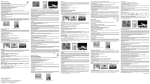
1
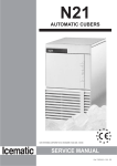
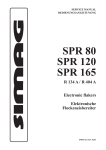
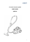
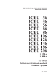
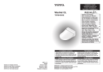
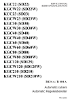
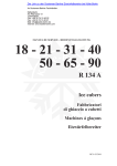
SD 18
R 134a
PRO
VIS
O
IRE
-
SEU
L EN
ANG
LAI
S, IT
ALI
EN
ET A
LLE
MA
ND
SERVICE MANUAL - MANUALE DI SERVIZIO
MANUEL DE SERVICE - BEDIENUNGSANLEITUNG
Ice cubers
Fabbricatori
di ghiaccio a cubetti
Machines á glaçons
Kegeleisbereiter
REV. 03/2003
a)
TABLE OF CONTENTS
PAGE
INDICE
PAG
TABLE DES MATIERES
PAGE
INHALT
SEITE
GENERAL INFORMATION
AND INSTALLATION
1
INFORMAZIONI GENERALI
ED INSTALLAZIONE
8
INFORMATIONS GENERALES
ET INSTALLATION
15
ALLGEMEINES UND
INSTALLATION
Introduction
Unpacking and inspection
Location and levelling
1
1
1
Introduzione
8
Disimballaggio ed ispezione 8
Posizionamento e livellamento 10
Introduction
15
Déballage et examen
15
Logement et mise de niveau 15
Einleitung
22
Auspacken und Inspektion 22
Maschinenplatz und lotgerechte
Aufstellung
28
Electrical connection
Water supply and drain
connection
Final check list
Installation practice
1
2
3
3
Collegamenti elettrici
Alimentazione idraulica
e scarico
Controllo finale
Schema di installazione
9
10
12
Branchement électrique
Branchement d’arrivée
et d’évacuation eau
Liste de contrôle final
Schema d’installation
16
17
17
Elektrische Anschlüße
Wasserversorgung und
Abflußleitungen
Schlußkontrollen
Installation
23
24
24
OPERATING INSTRUCTION
4
ISTRUZIONI DI
FUNZIONAMENTO
11
MISE EN SERVICE
18
BETRIEBSANLEITUNG
25
Start up
Operational checks
4
4
Avviamento
11
Controlli durante il funzion. 11
Démarrage
18
Contrôle pendant le fonctionn. 18
Inbetriebnahme
Kontrolle bei Betrieb
25
25
OPERATING PRINCIPLES
5
PRINCIPIO DI
FUNZIONAMENTO
12
PRINCIPE DE
FONCTIONNEMENT
19
FUNKTIONSSYSTEME
26
Freezing cycle
Harvest cycle
5
6
Ciclo di congelamento
Ciclo di scongelamento
12
12
Cycle de congélation
Cycle de démoulage
19
19
Gefrierprozess
Abtauprozess
26
26
WARTUNGS UND
REINIGUNGSANLEITUNGEN
28
CLEANING INSTRUCTIONS OF
WATER SYSTEM
7
9
ISTRUZIONI PER LA PULIZIA
DEL CIRCUITO IDRAULICO 14
15
INSTRUCTION DE NETTOYAGE
DU CIRCUIT HYDRAULIQUE
21
22
23
b)
c)
TECHNICAL SPECIFICATIONS - SPECIFICHE TECNICHE - DONNÉES TECHNIQUE - TECHNISCHE ANGABEN
Electric voltage
Alimentazione elettrica
Alimentation électrique
Normale Netzspannung
230/50/1
-10 ÷ +10%
Condensation
Condensazione
Condensation
Kühlung
Air
Aria
Air
Luft
Bin capacity (kg)
Capacità contenitore (kg)
Capacité bac glaçons (kg)
Speicher Kapazität (kg)
6,5
Net weight (kg)
Peso netto (kg)
Poids net (kg)
Netto Gewicht (kg)
33
Cubes per cycle
Cubetti per ciclo
Glaçons par cycle
Würfel per Fase
15
Compressor power HP
Potenza compressore CV
Puissance compresseur CV
Kompressorleistung PS
1/6
Running amps
Amperaggio di marcia
Ampérage en marche
Ampere
1,2
Start amps
Amperaggio d’avv.
Ampérage de démarr.
Start Ampere
6,7
Power (Watts)
Potenza (Watt)
Puissance (Watts)
Leistung (Watt)
340
Power cons. in 24 hrs (Kwh)
Consumo elettr. in 24 ore (Kwh)
Cons. electr. en 24 hrs (Kwh)
Stromverbrauch in 24 Std. (kWh)
7
Wire size (mm2)
Sezione cavi (mm2)
Section fils (mm2)
Kabelanzahl (mm2)
3x1
Water consumption (lt/hr)
Consumo acqua (lt/ora)
Consommation eau (lt/hr)
Wasserverbrauch (lt/std)
5
Refrig. charge R 134 A (gr)
Carica refrig. R 134 A (gr)
Charge refrig. R 134 A (gr)
Kühlmittel - Füll. R 134 A (gr)
Refrigerant metering device
Disp. espansione refrigerante
Détente du Rèfrigérant
Kältemittel - Expansionssystem
210
Capillary tube
Tubo capillare
Tube Capillaire
Kapillarrohr
Water - Acqua - Eau - Wasser: 15°C (60°F)
Envir. - Amb. - Amb. - Raum: 21°C (84°F)
OPERATING PRESSURES - PRESSIONI DI FUNZIONAMENTO - PRESSIONES DE FONCTIONNEMENT - BETRIEBSDRÜCKE
Air cooled - Raffr. ad aria
Refroid. à air - Luftgekühlt
Discharge pressure - Pressione di mandata
Haute pression - Hochdruckbereich
Suction pressure - Pressione di aspirazione
Basse pression - Niederdrück
Freezing cycle - Ciclo di congelamento
Cycle de Congélation - Gefrierfase
End of freezing cycle - Fine ciclo di congelamento
Fin du cycle de congélation - Ende der Gefrierfase
8 ÷ 9 bar
118 ÷ 132 psig
0,8 ÷ 0.1 bar
11 ÷ 1.5 psig
d)
WIRING DIAGRAM - SCHEMA ELETTRICO - SCHÉMA ÉLECTRIQUE - SCHALTUNGSSCHEMA
AIR COOLED - RAFFREDDAMENTO AD ARIA.
REFROIDISSEMENT A AIR - LUFT GEKÜHLT
B
N
A
M
GV
-
WHITE - BIANCO - BLANC - WEIB
BLACK - NERO - NOIR - SCHWARZ
BLUE - BLU - BLEU - BLAU
BROWN - MARRONE - MARRON - BRAUN
YELLOW GREEN - GIALLO VERDE
JAUNE VERT - GELB GRUEN
e)
RAFFREDDAMENTO AD ARIA - AIR COOLED MODELS
CONDENSATION PAR AIR - LUFTKÜHLUNG
Kg.
20
°C
19
10
18
20
17
16
30
15
14
35
13
12
11
10
9
25
20
15
10
TEMPERATURA ACQUA - WATER TEMPERATURE
TEMPÉRATURE DE L'EAU - WASSERTEMPERATUR
°C
TEMPERATURA AMBIENTE - AMBIENT TEMPERATURE
TEMPÉRATURE AMBIANT - RAUMTEMPERATUR
PRODUZIONE GHIACCIO (KG PER 24 ORE) - ICE PRODUCED (KG. PER 24 HRS)
PRODUCTION DE GLACE (KG.PAR 24 HEURES) - EISWÜRFELPRODUKTION (KG.IN 24 STD.)
Capacità di produzione - Ice making capacity - Capacité de production - Eisproduktionskapazität
Page 1
GENERAL INFORMATION
AND INSTALLATION
A.
INTRODUCTION
These Cubers are quality designed, engineered
and manufactured.
Their ice making systems are thoroughly tested
providing the utmost in flexibility to fit the needs
of a particular user.
These icemakers have been engineered to our
own rigid safety and performence standards.
NOTE. To retain the safety and performance
built into this icemaker, it is important that
installation and maintenance be conducted
in the manner outlined in this manual.
B.
8. Remove the manufacturer’s registration
card from the inside of the User Manual and fillin all parts including: Model and Serial Number
taken from the data plate.
Forward the completed self-addressed
registration card to the factory.
UNPACKING AND INSPECTION
1. Visually inspect the exterior of the packing
and skid. Any severe damage noted should be
reported to the delivering carrier and a concealed
damage claim form filled in subjet to inspection of
the contents with the carrier’s representative
present.
2. a) Cut and remove the plastic strip securing
the carton box to the skid.
b) Cut open the top of the carton and remove
the polystyre protection sheet.
c) Pull out the polystyre posts from the
corners and then remove the carton.
3. Remove the front and the rear panels of the
unit and inspect for any concealed damage.
Notify carrier of your claim for the concealed
damage as steted in step 1 above.
C.
LOCATION AND LEVELLING
WARNING. This Ice Cuber is designed for
indoor installation only. Extended periods
of operation at temperatures exceeding
the following limitations will constitute
misuse under the terms of the
Manufacturer’s Limited Warranty
resulting in LOSS of warranty coverage.
1. Position the unit in the selected permanent
location.
Criteria for selection of location include:
a) Minimum room temperature 10°C and
maximum room temperature 35°C.
b) Water inlet temperatures: minimum 5°C
and maximum 40°C.
c) Well ventilated location for air cooled
models. Clean the air cooled condenser at
frequent intervals.
d) Service access: adequate space must
be left for all service connections through the
rear of the ice maker. A minimum clearance of 15
cm (6") must be left at the sides of the unit for
routing cooling air drawn into and exhausted out
of the compartment to maintain proper
condensing operation of air cooled models.
NOTE. With the unit in “built-in” conditions,
the ice production is gradually reduced in
respect to the levels shown in the graph.
4. Remove all internal support packing and
masking tape.
The daily ice-making capacity is directly
related to the condenser air inlet temperature, water temperature and age of the machine.
5. Check that refrigerant lines do not rub
against or touch other lines or surfaces, and that
the fan blade moves freely.
To keep your CUBER at peak performance
levels, periodic maintenance checks must
be carried out as indicated on Cleaning
Section of this manual.
6. Use clean damp cloth to wipe the surfaces
inside the storage bin and the outside of the
cabinet.
2. Level the unit in both the left to right and
front to rear directions.
7. See data plate on the rear side of the unit
and check that local main voltage corresponds
with the voltage specified on it.
D.
CAUTION. Incorrect voltage supplied to
the icemaker will void your parts
replacement program.
ELECTRICAL CONNECTIONS
See data plate for current requirements to
determine wire size to be used on electrical
connections. All icemakers require a solid earth
wire.
Page 2
The ice machines are supplied from the factory
completely pre-wired and require only electrical
power connections to wire cord provided on the
back of the unit.
Make sure that the ice machine is connected to
its own circuit and individually fused (see data
plate for fuse size).
The maximum allowable voltage variation should
not exceed -10% and +10% of the data plate
rating. Low voltage can cause faulty functioning
and may be responsible for serious damage to
the overload switch and motor windings.
NOTE. All external wiring should conform to
national, state and local standards and
regulations.
Check voltage on the line and the ice maker’s
data plate before connecting the unit.
Since water is the most important single ingredient
in producting ice you cannot emphasize too
much the three items listed above.
Low water pressure, below 1 bar may cause
malfunction of the ice maker unit.
Water containing excessive minerals will tend to
produce cloudy coloured ice cubes, plus scale
built-up on parts of the water system.
Water supply
Connect the 3/4" male fitting of the solenoid
water inlet valve, using the flexible tubing supplied,
to the cold water supply line with regular plumbing
fitting and a shut-off valve installed in an
accessible position between the water supply
line and the unit.
Water drain
E.
WATER SUPPLY AND DRAIN
CONNECTIONS
General
When choosing the water supply for the ice cuber
consideration should be given to:
a) Length of run
b) Water clarity and purity
c) Adequate water supply pressure
The recommended drain tube is a plastic or
flexible tube with 18 mm (3/4") I.D. runs to an
open trapped and vented drain. When the drain
is a long run, allow 3 cm pitch per meter (1/4"
pitch per foot).
A vertical open vent, at the unit drain connection,
is also required for proper sump drainage.
NOTE. The water supply and the water drain
must be installed to conform with the local
code. In some case a licensed plumber and/
or a plumbing permit is required.
Page 3
F.
FINAL CHECK LIST
1 bar (14 psi).
1. Is the unit in a room where ambient
temperatures are within a minimum of 10°C even
in winter months?
2. Is there at least a 15 cm (6") clearance
around the unit for proper air circulation?
3.
8. Have the bin liner and cabinet been wiped
clean?
9. Has the owner/user been given the User
Manual and been instructed on the importance of
periodic maintenance checks?
Is the unit level? (IMPORTANT)
4. Have all the electrical and plumbing
connections been made, and is the water supply
shut-off valve open?
5. Has the voltage been tested and checked
against the data plate rating?
6. Has the water supply pressure been
checked to ensure a water pressure of at least
G.
7. Check all refrigerant lines and conduit lines
to guard against vibrations and possible failure.
10. Has the Manufacturer’s registration card
been filled in properly? Check for correct model
and serial number against the serial plate and
mail the registration card to the factory.
11. Has the owner been given the name and the
phone number of the authorized Service Agency
serving him?
INSTALLATION PRACTICE
1.
2.
3.
4.
5.
6.
7.
8.
9.
Hand shut-off valve
Water filter
Water supply line (flexible hose)
3/4" male fitting
Vented drain
Open trapped vented drain
Drain fitting
Main switch
Power line
WARNING. This icemaker is not designed for outdoor installation and will not function in
ambient temperatures below 10°C or above 35°C.
This icemaker will malfunction with water temperatures below 5°C or above 40°C.
Page 4
OPERATING INSTRUCTIONS
START UP
After having correctly installed the ice maker and
completed the plumbing and electrical
connections, perform the following “Start-up”
procedure.
A.
Remove the unit front panel and locate
the cleaning switch on the control box.
B.
Set the cleaning switch in the cleaning
position. This will close the electrical circuit to the
water inlet valve and to the hot gas valve
C.
Switch ON the power line disconnect
switch. Unit will start up in defrost cycle mode.
During this cycle the components energized are:
WATER INLET SOLENOID VALVE
HOT GAS SOLENOID VALVE
The Water pump and the Fan motor are also in
operation.
D.
Let unit stay in defrost cycle for about
three/four minutes till water is coming out from
the drain hose, then move the cleaning switch to
the operation position.
NOTE. During the defrost cycle, the water
inlet solenoid valve is energized. The water
flows through the valve to the back side of
the evaporator platen and then down to fill up
the icemaker sump tank for the next freezing
cycle.
OPERATIONAL CHECKS
E.
The unit now starts its first freezing cycle
with the following components in operation:
COMPRESSOR
WATER PUMP
FAN MOTOR in air cooled version
F.
Check to see through the ice discharge
opening that the spray system is correctly seated
and that the water jets uniformely reach the
inverted molds; also make sure that the plastic
curtain is hanging freely and there is not excessive
water spilling through it.
G.
The ice making process takes place
thereby, with the water sprayed on the inverted
molds that gets gradually refrigerated by the
heat exchanged with the refrigerant flowing into
the evaporator serpentine.
H.
When the evaporator temperature reaches
a preset value the evaporator thermostat or cube
size control changes its contacts; the freezing
cycle ends and starts the defrost or harvest
cycle.
I.
Check, during the first defrost/harvest
cycle, that the incoming water flows correctly
into the sump reservoir in order to re-fill it and the
surplus overflows through the overflow drain
tube.
J.
Check the texture, the right weight and
dimension of ice cubes just released.
If not, wait for the second defrost/harvest cycle
before performing any adjustment.
K.
If required, the length of the freezing cycle
can be modified by turning with very little
movements (6 degree or 1 minute each time) the
knob of the cube size control evaporator
thermostat located in front of the control box until
the desired size is achieved.
If the ice cubes are shallow and cloudy, it is
possible that the ice maker runs short of water
during the end of the freezing cycle or, the quality
of the supplied water requires the use of an
appropriate water filter or conditioner.
L.
During the defrost or harvest cycle hold a
handful of ice cubes against the bulb of the
storage bin thermostat; the icemaker switch OFF
in about one-two minutes.
Take out the ice from the storage bin thermostat.
The ice maker should restart automatically in
three-four minutes.
NOTE. The bin thermostat is factory set at
1°C OUT and 4°C IN.
M.
Re-fit the unit front panel then instruct the
owner/user on the general operation of the ice
machine and about the cleaning and care it
requires.
Page 5
PRINCIPLE OF OPERATION
How it works
In the ice makers the water used to make the ice
is kept constantly in circulation by a water pump
which primes it to the spray system nozzles from
where it is diverted on the inverted molds of the
evaporator (Fig. A).
A small quantity of the sprayed water freezes into
ice; the rest of it cascades by gravity into the
sump assembly below for recirculation.
The above values are in relation as well to the
ambient temperature of the ice maker site and
they are subject to rise with the increase of this
temperature.
At the start of the freezing cycle the refrigerant
suction or lo-pressure lowers rapidly to 1.0 bar
- 14 psig then it declines gradually - in relation
with the growing of the ice thickness - to reach,
at the end of the cycle, approx. 0÷0.1 bar - 0÷1.5
psig with the cubes fully formed on the molds.
FREEZING CYCLE (Fig. B)
DEFROST OR HARVEST CYCLE (Fig. D)
The hot gas refrigerant discharged out from the
compressor reaches the condenser where, being
cooled down, condenses into liquid. Flowing into
the liquid line it passes through the drier/filter,
then it goes all the way through the capillary tube
where it looses its pressure.
Next the refrigerant enters into the evaporator
serpentine (which has a larger diameter then the
capillary tube) and starts to boil off; this reaction
is emphasized by the heat transferred by the
sprayed water.
The refrigerant then increases in volume and
changes entirely into vapor.
The vapor refrigerant then passes through the
suction accumulator (used to prevent that any
small amount of liquid refrigerant may reach the
compressor) and through the suction line. In both
the accumulator and the suction line it exchanges
heat with the refrigerant flowing into the capillary
tube (warmer), before to be sucked in the
compressor and to be recirculated as hot
compressed refrigerant gas.
The freezing cycle is controlled by the evaporator
thermostat which has its bulb in contact with the
evaporator serpentine.
The electrical components in operation during
the freezing cycle are:
COMPRESSOR
WATER PUMP
FAN MOTOR
The refrigerant head pressure is gradually
reduced from a value of approx. 11 bars (155
psig) at the beginning of the freezing cycle with
the unit at 21°C ambient temperature, to a
minimun value of approx. 7 bars (100 psig) just
at the end of the freezing cycle few seconds
before the starting of the defrost cycle.
The declining of the pressure is relied to the
reduction of the evaporating pressure, caused
by the progressive growth of the ice thickness on
the inverted molds and to the flow of air drown
through the air cooled condenser by the fan
motor.
When the temperature of the evaporator
thermostat, in contact with the evaporator
serpentine, drops to a pre-set value it changes its
electrical contacts energizing the following
components:
COMPRESSOR
WATER INLET SOLENOID VALVE
HOT GAS SOLENOID VALVE
The incoming water, passing through the water
inlet valve and the flow control, runs over the
evaporator platen and then flows by gravity
through the interstices down into the sump/
reservoir (Fig. C).
The water filling the sump/reservoir forces part of
the surplus water from the previous freezing
cycle to go out to the waste through the overflow
pipe. This overflow limits the level of the sump
water which will be used to produce the next
batch of ice cubes.
Meanwhile the refrigerant, as hot gas discharged
from the compressor, flows through the hot gas
valve directly into the evaporator serpentine bypassing the condenser.
The hot gas circulating into the serpentine of the
evaporator warms up the copper molds causing
the harvest of the ice cubes. The ice cubes,
released from the inveted molds, drop by gravity
onto a slanted cube chute, then through a
curtained opening they fall into the storage bin.
When the temperature of the evaporator
thermostat bulb reaches the value of +3÷4°C
their electrical contacts move back to the previous
position activating a new freezing cycle and
deenergizing both the hot gas and the water inlet
valves (closed).
NOTE. The length of the defrost/harvest
cycle (not adjustable) changes according
to the ambient temperature (shorter for hi
ambient temperature and longer for low
one).
Page 6
COMPONENTS DESCRIPTION
A.
WATER PUMP
The water pump operates continually throughout
the freezing cycle.
The pump primes the water from the sump to the
spray system and through the spray nozzles
sprays it into the inverted cup molds to be frozen
into crystal clear ice cubes.
It is recommended that the pump motor bearings
be checked at least every six months.
B.
HOT GAS SOLENOID VALVE
The hot gas solenoid valve consists basically in
two parts: the valve body and the valve coil.
Located on the hot gas line, this valve is energized
by the contacts 3-2 of the evaporator thermostat
during the defrost cycle.
During the defrost cycle the hot gas valve coil is
activated so to attract the hot gas valve piston in
order to give way to the hot gas discharged from
compressor to flow directly into the evaporator
serpentine to defrost the formed ice cubes.
D.
F.
FAN MOTOR
The fan motor is electrically connected in parallel
to the water pump and it operates continuously
only during the freezing cycle keeping the proper
head pressure by circulating air through the
condenser fins.
G.
COMPRESSOR
The hermetic compressor is the heart of the
refrigerant system and it is used to circulate and
retrieve the refrigerant throughout the entire
system. It compresses the low pressure
refrigerant vapor causing its temperature to rise
and become high pressure hot vapor (hot gas)
which is then released through the discharge
valve.
BIN THERMOSTAT
The bin thermostat control body is located in the
front of control box behind the front louvered
panel.
The thermostat sensing tube is located into a
bulb holder on the side wall of the ice storage bin
where it automatically shuts the icemaker OFF
when in contact with the ice and re-starts the
icemaker when the ice is removed. Factory
settings are 1°C OUT and 4°C IN.
E.
NOTE. The thermostat is very sensitive!
By a little movement of the knob correspond
a big size change of the ice cubes. If
necessary only, it's recommended to make
max 1/20 of turn regulation each time.
WATER INLET SOLENOID VALVE 3/4 MALE FITTING
The water inlet solenoid valve is energized only
during the defrost cycle.
When energized it allows a metered amount of
incoming water to flow over the evaporator cavity
to assist the hot gas in defrosting the ice cubes.
The water running over the evaporator cavity
drops by gravity, through the dribbler interstices
of the platen, into the sump reservoir.
C.
This control determines the length of the freezing
cycle and correspondingly the size of the cubes.
A lower setting will produce a larger cube
(oversize) while a higher setting a smaller cuber
(shallow size).
When closed on contacts 3-2 it activates the
defrost or harvest cycle components.
The cube size control is set up in the factory
(knob in the black dot position) and doesn't
require any adjustment when the ambient
temperature remains between 10 and 35°C.
CUBE SIZE CONTROL (EVAPORATOR
THERMOSTAT)
The cube size control (evaporator thermostat)
body is located in the front of control box behind
the front louvered panel; it’s basically a reverse
acting temperature control which closes the
contacts 3-2 when its temperature decreases
and closes the opposite contacts 3-4 when the
temperature rises.
The thermostat sensing bulb is located into a
plastic tube (bulb holder) secured by two clips
directly to the evaporator serpentine.
H.
WATER SPRAY SYSTEM
Through its nozzles it sprays the water on each
individual inverted mold to be frozen into ice.
I
SAFETY HI TEMPERATURE
THERMOSTAT
Located on the bottom part of the control box it is
a manual reset switch that trips OFF the operation
of the machine when its bulb (located on the
liquid line just before the drier) reaches the
temperature of 80°C.
J.
CLEANING SWITCH
Located on the bottom left side of the control box
is used to energize the water inlet and the hot gas
valves so to charge the water into the sump tank
of the machine.
Page 7
MAINTENANCE AND CLEANING INSTRUCTIONS
CLEANING INSTRUCTIONS OF WATER
SYSTEM
1. Remove the front and top panels to gain
access either to the control box and to the
evaporator.
2. Make sure that all ice cubes have been
released from their molds, then switch off the
unit.
3. Prepare the cleaning solution by diluting in
a plastic container one or two liters of warm water
(45°-50°C) with a 0,1-0,2 liters of Ice Machine
Cleaner.
WARNING. The Ice Machine Cleaner
contains Phosphoric and Hydroxyacetic
acids.
These compounds are corrosive and may
cause burns if swallowed, DO NOT induce vomiting. Give large amounts of water
or milk. Call Physician immediately.
In case of external contact flush with
water. KEEP OUT OF THE REACH OF
CHILDREN.
4. Scoop out all the ice cubes stored into the
bin in order to prevent them from being
contaminated with the cleaning solution then
flush out the water from the sump reservoir by
removing the overflow stand-pipe.
5. Remove the evaporator cover then slowly
pour onto the evaporator platen the cleaning
solution. With the help of a brush dissolve the
most resistant and remote scale deposits in the
platen.
6. Turn the CLEANING switch on "II-CLEAN",
close the water tap and switch on the machine.
7. Allow the ice maker to operate for about 20
minutes.
NOTE. The amount Cleaner and the time
needed for the cleaning of water system
depends of the water conditions.
8. Switch OFF then flush out the cleaning
solution from the sump reservoir then pour onto
the evaporator cavity two or three liters of clean
potable water to rinse the molds and the platen.
9. Switch ON the machine. The water pump is
again in operation to circulate the water in order
to rinse the entire water system.
10. Do the operation as per steps 8 and 9 twice
so to be sure no more traces of descaling solution
remains into the sump.
11. Pour on the upper side of the evaporator
platen fresh water with a capfull of disinfectant
solution then turn again the machine in normal
operating mode so to sanitize all the water system
for approx. 10 minutes.
NOTE. Do not mix descaling with disinfectant
solution to avoid the generation of a very
aggressive acid.
12. Flush out the disinfectant solution from the
sump reservoir, open the water tap then switch
on the machine.
13. When water starts overflowing through
the drain line, set the switch to "operation"
position "I-ON". The unit is now ready to resume
normal operation.
14. Place again the evaporator cover and the
unit service panels.
15. At completion of the freezing and harvest
cycle make sure of proper texture and clearness
of the ice cubes and that, they do not have any
acid taste.
ATTENTION. In case the ice cubes are
cloudy-white and have an acid taste, melt
them immediately by pouring on them
some warm water. This to prevent that
somebody could use them.
16. Wipe clean and rinse the inner surfaces of
the storage bin.
REMEMBER. To prevent the accumulation
of undesirable bacteria it is necessary to
sanitize the interior of the storage bin with an
anti-algae disinfectant solution every week.
Pagina 8
INFORMAZIONI GENERALI
ED INSTALLAZIONE
A.
INTRODUZIONE
I fabbricatori di ghiaccio in cubetti sono stati
progettati e costruiti con un elevato standard
qualitativo.
Essi vengono collaudati interamente per diverse
ore e sono in grado di assicurare il massimo
rendimento relativamente ad ogni particolare
uso e situazione.
NOTA. Per non compromettere o ridurre le
caratteristiche di qualità e sicurezza di questo fabbricatore di ghiaccio si raccomanda,
nell’effettuare l’installazione e le operazioni
periodiche di manutenzione, di attenersi scrupolosamente a quanto prescritto in questo
manuale.
B.
DISIMBALLAGGIO ED ISPEZIONE
1. Ispezionare visivamente l’imballo esterno
in cartone e il basamento in legno usati per la
spedizione. Qualsiasi danno evidente sull’imballo esterno deve essere riferito allo spedizioniere;
in questo caso, procedere ad ispezionare l’apparecchio con il rappresentante dello spedizioniere
presente.
2. a) Tagliare e rimuovere i nastri in plastica
che mantengono sigillato l’imballo di cartone.
b) Aprire la parte superiore dell’imballo e
togliere i fogli e gli angolari protettivi di polistirolo.
sponda a quello riportato sulla targhetta dell’apparecchio.
ATTENZIONE. Un errato voltaggio dell’alimentazione elettrica annullerà automaticamente il vostro diritto alla garanzia.
8. Compilare la cartolina di garanzia posta
all’interno del Manuale d’Uso, segnando sia il
modello che il numero di serie dell’apparecchio
rilevandolo dalla targhetta fissata al telaio.
Spedire la cartolina debitamente compilata al
costruttore.
C.
POSIZIONAMENTO E LIVELLAMENTO
ATTENZIONE. Questo fabbricatore di
ghiaccio è stato progettato per essere
installato all’interno di locali in cui la
temperatura ambiente non scenda mai al
di sotto di 10°C ne superi i 35°C.
Periodi prolungati di funzionamento a
temperature al di fuori dei seguenti limiti
costituiscono cattivo uso secondo i termini di garanzia e fanno decadere automaticamente il vostro diritto alla garanzia.
1. Posizionare l’apparecchio nel luogo di installazione definitivo.
I criteri per la sua scelta sono:
a) Minima temperatura ambiente 10°C e
massima temperatura ambiente 35°C.
b) Temperature dell’acqua di alimentazione: minima 5°C massima 40°C.
c) Sollevare l’intero cartone sfilandolo dall’apparecchio.
c) Luogo ben aerato per assicurare un
efficace ventilazione all’apparecchio e quindi un
corretto funzionamento del condensatore.
3. Togliere il pannello frontale ed il pannello
posteriore dell’apparecchio ed ispezionare lo
stesso onde accertare se abbia subito danni.
Notificare allo spedizioniere eventuali danni subiti come riportato al punto 1.
d) Spazio adeguato per i collegamenti di
servizio previsti nella parte posteriore dell’apparecchio. Lasciare almeno 15 cm di spazio attorno all’unità così da permettere una corretta ed
efficace circolazione d’aria soprattutto nei modelli raffreddati ad aria.
4. Togliere tutti i supporti interni usati per la
spedizione e i nastri adesivi di protezione.
5. Controllare che le tubazioni del circuito
refrigerante non tocchino altre tubazioni o superfici, e che il ventilatore giri liberamente.
6. Usando un panno pulito e umido, pulire le
pareti interne del contenitore del ghiaccio e le
superfici esterne dell’apparecchio.
7. Osservare i dati riportati sulla targhetta fissata alla parte posteriore del telaio vicino ai
raccordi idraulici ed elettrici, e verificare che il
voltaggio della rete elettrica disponibile corri-
NOTA. Con l’apparecchio incassato la produzione di ghiaccio diminuisce rispetto a
quanto indica il diagramma.
La capacità di produzione giornaliera varia
con il variare della temperatura ambiente,
dell’acqua di alimentazione e dello spazio
intorno all’apparecchio.
Per mantenere la produzione del vostro
fabbricatore di ghiaccio a cubetti al massimo della sua condizione è necessario eseguire la manutenzione periodica come prescritto nel relativo capitolo di questo manuale.
Pagina 9
2. Livellare l’apparecchio in entrambe le direzioni, dall’anteriore alla posteriore e da sinistra a
destra mediante i piedini.
NOTA. Questo fabbricatore di ghiaccio incorpora dei componenti delicati e di massima precisione pertanto bisogna evitargli urti
e scossoni violenti.
D.
COLLEGAMENTI ELETTRICI
Osservare la targhetta dell’apparecchio così da
determinare, in funzione dell’amperaggio indicato, tipo e sezione del cavo elettrico da usarsi.
Tutti gli apparecchi sono muniti di un cavo di
alimentazione elettrica per cui si richiede un
collegamento dello stesso ad una linea elettrica
provvista di cavo di messa a terra e che faccia
capo ad un proprio interruttore magneto-termico
munito di fusibili adeguati, come indicato nella
targhetta di ogni singolo apparecchio.
La variazione massima di voltaggio consentita
non deve eccedere il 10% del valore di targa o
essere inferiore al 10% dello stesso. Un basso
voltaggio può causare un funzionamento anomalo e può essere la causa di seri danni alle
protezioni ed agli avvolgimenti elettrici.
NOTA. Tutti i collegamenti esterni devono
essere fatti a regola d’arte in conformità con
quanto stabilito dalle norme locali da parte di
personale qualificato.
Prima di collegare il fabbricatore di ghiaccio alla
linea elettrica accertarsi ancora una volta che il
voltaggio dell’apparecchio, specificato sulla
targhetta, corrisponda al voltaggio misurato.
E.
ALIMENTAZIONE IDRAULICA E
SCARICO
Premessa
Nella scelta dell’alimentazione idraulica al
fabbricatore di ghiaccio a cubetti si deve tenere
presente:
a) Lunghezza della tubazione
b) Limpidezza e purezza dell’acqua
c) Adeguata pressione dell’acqua di alimentazione
Una bassa pressione dell’acqua di alimentazione, inferiore ad 1 bar, può causare dei disturbi di
funzionamento dell’apparecchio. L’uso di acque
contenenti una quantità eccessiva di minerali
darà luogo ad una produzione di cubetti di ghiaccio opachi e ad una notevole incrostazione delle
parti interne del circuito idraulico.
Alimentazione idraulica
Collegare il raccordo da 3/4 di pollice maschio
della valvola solenoide di ingresso acqua alla
linea di alimentazione idrica utilizzando il tubo in
plastica rinforzato del tipo alimentare atossico
fornito.
La linea di alimentazione idraulica deve essere
munita di un rubinetto di intercettazione posto in
un luogo accessibile nei pressi dell’apparecchio.
Scarico acqua
Si consiglia di usare, come tubo di scarico, un
tubo in plastica rigida avente diametro interno di
18 mm.
Lo scarico dell’acqua in eccesso avviene per
gravità; per avere un regolare deflusso è indispensabile che lo scarico disponga di una presa
d’aria e vada in un sifone aperto.
NOTA. Tutti i collegamenti idraulici devono
essere eseguiti a regola d’arte in conformità
con le norme locali. In alcuni casi è richiesto
l’intervento di un idraulico patentato.
Pagina 10
F.
CONTROLLO FINALE
1. L’apparecchio è stato installato in un locale
dove la temperatura ambiente è di almeno 10°C
anche durante i mesi invernali?
refrigerante e del circuito idraulico verificando se
esistono vibrazioni o sfregamenti. Controllare
inoltre che le fascette stringitubo siano ben serrate e che i cavetti elettrici siano fermamente
collegati.
2. Ci sono almeno 15 cm di spazio dietro ed ai
lati dell’apparecchio onde avere una efficace
ventilazione del condensatore?
8. Sono stati controllati i bulloni di ancoraggio
del compressore? Permettono a questi di oscillare sui propri supporti?
3. L’apparecchio è ben livellato? (IMPORTANTE)
9. Le pareti interne del contenitore del ghiaccio e le pareti esterne dell’apparecchio sono
state pulite?
4. L’apparecchio è stato collegato alla linea di
alimentazione elettrica? É stato eseguito il collegamento alle tubazioni dell’acqua di alimentazione e di scarico?
5. É stato controllato il voltaggio della linea di
alimentazione elettrica? Corrisponde al voltaggio specificato sulla targhetta dell’apparecchio?
6. É stata controllata la pressione dell’acqua
di alimentazione in modo da assicurare all’apparecchio una pressione di ingresso di almeno 1
bar?
7.
Controllare tutte le tubazioni del circuito
G.
10. É stato consegnato il libretto di istruzione e
sono state date al proprietario le istruzioni necessarie per il funzionamento e la manutenzione
periodica dell’apparecchio?
11. La cartolina di garanzia è stata compilata?
Controllare il numero di serie ed il modello sulla
targhetta dell’apparecchio, quindi spedirla al
costruttore.
12. É stato dato al proprietario il nome ed il
numero telefonico del servizio di assistenza tecnica autorizzato della zona?
SCHEMA DI INSTALLAZIONE
1.
2.
3.
4.
5.
6.
7.
8.
9.
Rubinetto di intercettazione
Filtro acqua
Linea di alimentazione idraulica
Raccordo da 3/4 di pollice
Scarico ventilato
Scarico acqua con sifone ventilato
Raccordo di scarico
Interruttore principale
Linea elettrica
ATTENZIONE. Questo fabbricatore di ghiaccio non è stato progettato per essere installato
all’aperto o per funzionare a delle temperature ambienti inferiori a 10°C o superiori a 35°C.
Lo stesso vale per la temperatura dell’acqua di alimentazione che non deve essere inferiore
a 5°C o superiore a 40°C.
Pagina 11
ISTRUZIONI DI
FUNZIONAMENTO
AVVIAMENTO
Dopo aver correttamente installato l'apparecchio ed averlo collegato alla rete elettrica ed
idraulica, seguire la seguente procedura per
l'avviamento.
A. Togliere dal fabbricatore di ghiaccio il pannello frontale e localizzare l'interruttore di lavaggio.
B. Spostare l'interruttore di lavaggio sulla posizione "II CLEAN". Questo chiude il circuito
elettrico della valvola di ingresso dell'acqua e
della valvola gas caldo.
C. Spostare, a questo punto sia l'interruttore
posto sulla linea di alimentazione elettrica che
l'interruttore generale dell'apparecchio sulla posizione ON (acceso). L'apparecchio partirà nella
fase di sbrinamento con i seguenti componenti in
funzione:
VALVOLA INGRESSO ACQUA
VALVOLA GAS CALDO
Sono in funzione anche la Pompa ed il
Motoventilatore.
D. Lasciare funzionare la macchina nella fase
di sbrinamento per circa tre - quattro minuti fino
ad avere dell'acqua allo scarico dell'apparecchio. Quindi spostare l'interruttore di lavaggio
sulla posizione "I ON".
NOTA. Durante la fase di sbrinamento l'acqua entra nell'apparecchio, attraverso la valvola solenoide di ingresso dell'acqua, eccitata durante questa parte del ciclo, e attraverso
l'apposita tubazione è indirizzata sulla parte
superiore dell'evaporatore. Dopo aver coperto l'intera superficie di plastica
dell'evaporatore, l'acqua viene scaricata, attraverso le fessure di drenaggio, nella
vaschetta di raccolta, riempiendola.
E. L'apparecchio inizia così il suo primo ciclo
di congelamento con i seguenti componenti in
funzione:
COMPRESSORE
POMPA
MOTOVENTILATORE
F. Osservare attraverso l’apertura di scarico
dei cubetti che la barra spruzzante sia correttamente posizionata e che l’acqua venga uniformemente spruzzata sugli stampini rovesciati
dell’evaporatore.
Verificare che la tendina di plastica sia posizionata correttamente impedendo la fuoriuscita
dell’acqua attraverso le proprie lamelle.
G. Il processo di fabbricazione del ghiaccio ha
così inizio con l’acqua che viene continuamente
spruzzata sugli stampini rovesciati e con la temperatura dell’evaporatore che gradualmente si
abbassa.
H. Quando la temperatura dell'evaporatore
raggiunge un valore predeterminato il termostato evaporatore commuta i suoi contatti dando
luogo alla fine del ciclo di congelamento ed
all'inizio del ciclo di scongelamento.
I.
Verificare che durante la fase di
scongelamento l’acqua di alimentazione vada a
reintegrare quella precedentemente usata per la
produzione dei cubetti e che quella eccedente
trabocchi nel tubo di troppo pieno e fluisca nella
tubazione di scarico dell’apparecchio.
J. Osservare i cubetti di ghiaccio prodotti.
Questi devono essere della giusta dimensione.
Nel caso contrario, attendere il secondo ciclo di
produzione del ghiaccio, prima di effettuare qualsiasi regolazione.
K. Se necessario la durata del ciclo di
congelamento può essere modificata ruotando
con piccolissimi spostamenti (spostare di 1/20 di
giro per volta) la manopola del termostato
evaporatore posta nella parte frontale della scatola elettrica fino al raggiungimento della dimensione ottimale.
Controllare l'aspetto dei cubetti di ghiaccio prodotti: cubetti aventi delle corrette dimensioni
esterne ma particolarmente opachi, indicano
che il fabbricatore di ghiaccio ha avuto una
mancanza d'acqua durante la fase finale del
ciclo di congelamento o che, l'acqua usata per la
produzione del ghiaccio è di pessima qualità e
quindi si rende necessario l'uso di filtri adeguati
o di un condizionatore d'acqua.
L. Durante il ciclo di sbrinamento, coprire con
una manciata di cubetti il bulbo sensibile del
termostato contenitore e verificare lo spegnimento dell'apparecchio dopo circa due o tre
minuti.
Togliere la manciata di cubetti dal bulbo sensibile e controllare che l'apparecchio si rimetta in
moto in circa tre o quattro minuti.
M. Rimontare i pannelli precedentemente rimossi quindi istruire il proprietario sul funzionamento del fabbricatore di ghiaccio così come
sulle operazioni di pulizia ed igienizzazione del
medesimo.
Pagina 12
PRINCIPIO DI
FUNZIONAMENTO
Nei fabbricatori di ghiaccio l’acqua usata per la
produzione del ghiaccio è tenuta costantemente
in movimento da una pompa elettrica che attraverso un sistema spruzzante dirige l’acqua a
pressione moderata sugli stampini rovesciati
dell’evaporatore.
Qui una parte dell’acqua spruzzata ghiaccia
all’istante; il rimanente di essa ricade nel
sottostante serbatoio di recupero per essere
ricircolata.
CICLO DI CONGELAMENTO
Il refrigerante allo stato gassoso ed ad alta
temperatura viene pompato dal compressore e,
passando poi attraverso il condensatore, si trasforma in refrigerante allo stato liquido.
La linea del liquido permette al refrigerante di
fluire dal condensatore al tubo capillare attraverso il filtro deumidificatore. Durante il passaggio
attraverso il tubo capillare il refrigerante allo
stato liquido perde gradualmente parte della sua
pressione e conseguentemente parte della sua
temperatura. Successivamente raggiunge ed
entra nella serpentina dell’evaporatore.
L’acqua spruzzata sugli stampini rovesciati
dell’evaporatore cede calore al refrigerante circolante all’interno della serpentina, causandone
l’evaporazione, ed il conseguente cambiamento
del suo stato fisico, cioè da liquido diviene vapore. Il refrigerante allo stato vaporoso dopo essere passato attraverso l’accumulatore viene aspirato nuovamente nel compressore tramite la
linea di aspirazione.
Il ciclo di congelamento è regolato da un controllo della temperatura (termostato evaporatore)
che determina la durata del ciclo e di conseguenza la dimensione dei cubetti.
I componenti in funzione durante il ciclo di
congelamento sono:
IL COMPRESSORE
LA POMPA
IL VENTILATORE
Nei modelli raffreddati ad aria la pressione di
mandata del sistema refrigerante (alta pressione) cala progressivamente da un valore di circa
11 bar (con temperatura ambiente di 21°C), che
si riscontra all’inizio del ciclo di congelamento,
fino ad un valore minimo di 7 bar proprio alla fine
del ciclo di congelamento.
Questi valori sono influenzati della temperatura
dell’ambiente in cui è installato l’apparecchio e
aumentano proporzionalmente con l’aumentare
di quest’ultima.
Con apparecchi installati in condizioni normali
(21°C ambiente) la pressione di aspirazione o
bassa pressione scende rapidamente a 1 bar
all’inizio del ciclo di congelamento, cioè quando
il cubetto di ghiaccio inizia a formarsi, declinando
lentamente a circa a 0÷0.1 bar allorché il cubetto
di ghiaccio è completamente formato.
CICLO DI SCONGELAMENTO O
SBRINAMENTO
Al momento in cui il termostato evaporatore
sente la temperatura corrispondente ai cubetti di
ghiaccio di dimensione piena, i contatti dello
stesso cambiano posizione alimentando i seguenti componenti:
COMPRESSORE
VALVOLA DI INGRESSO ACQUA
VALVOLA DEL GAS CALDO
L’acqua in immissione passa attraverso la valvola solenoide di ingresso ed il controllo di flusso
che è posto all’interno della medesima, arriva
sulla parte superiore dell’evaporatore da dove
cola, attraverso le fessure di drenaggio, nel
sottostante serbatoio di pescaggio della pompa.
Il livello massimo dell’acqua nel serbatoio è limitato da un tubo di troppo pieno che ha la funzione
di indirizzare verso lo scarico l’acqua in eccesso.
Il refrigerante allo stato gassoso, pompato dal
compressore, viene ora dirottato dalla valvola del
gas caldo aperta direttamente alla serpentina
dell’evaporatore, seguendo il percorso più diretto cioè, non passando attraverso il condensatore.
Il gas caldo circolante all’interno della serpentina
dell’evaporatore, fa aumentare la temperatura
degli stampini causando quindi lo stacco dai
medesimi dei cubetti di ghiaccio.
I cubetti che si staccano cadono sopra una griglia
inclinata da dove scivolano attraverso l’apertura
con tendina a lamelle, per cadere all’interno del
contenitore del ghiaccio.
Grazie al fluire del gas caldo nella serpentina
dell'evaporatore, la temperatura dello stesso sale
e conseguentemente sale anche la temperatura
del bulbo sensibile del termostato evaporatore il
quale cambia i suoi contatti disattivando la bobina della valvola gas caldo e della valvola di
ingresso acqua ed attivando la pompa di circolazione dell'acqua e il ventilatore iniziando così un
nuovo ciclo di congelamento.
DESCRIZIONE DEI COMPONENTI
A. POMPA
La pompa opera in continuazione soltanto durante il ciclo di congelamento dirigendo l'acqua
verso la piastra spruzzante.
Dalla barra spruzzante l'acqua, attraverso gli
spruzzatori viene diretta sugli stampini rovesciati
subendo, in questa fase, una certa aerazione
permettendo così di ottenere un cubetto di ghiaccio solido e cristallino.
Si consiglia di controllare lo stato dei cuscinetti
almeno ogni sei mesi.
B.
VALVOLA SOLENOIDE DI INGRESSO
DELL'ACQUA - RACCORDO DA 3/4
GAS MASCHIO
La valvola solenoide di ingresso dell'acqua posta
nella parte posteriore dell'apparecchio, è eccitata solamente durante il ciclo di sbrinamento.
Quando è eccitata permette, ad una limitata quan-
Pagina 13
tità d'acqua, di fluire verso la parte superiore della
piastra evaporatore assistendo così il gas caldo
durante la fase di distacco dei cubetti. Quest'acqua
viene quindi scaricata dalla piastra dell'evaporatore,
attraverso le fessure di scarico, nel serbatoio di
raccolta sottostante da dove viene aspirata dalla
pompa e diretta alla barra spruzzante.
C.
VALVOLA SOLENOIDE DEL
GAS CALDO
La valvola solenoide del gas caldo è composta
essenzialmente da due parti, rispettivamente il
corpo e la bobina. Situata sulla linea di mandata
del compressore è attivata dai contatti 3-2 (seconda posizione), del termostato evaporatore
durante il ciclo di sbrinamento.
Durante il ciclo di sbrinamento la bobina, collocata sulla parte superiore della valvola gas caldo è
attivata attraendo pertanto il pistoncino posto
all'interno del corpo valvola.
Questo apre il passaggio al gas caldo pompato
dal compressore, consentendogli di fluire direttamente nella serpentina dell'evaporatore distaccando così i cubetti di ghiaccio dai bicchierini.
D.
TERMOSTATO CONTENITORE
Il tubo sensibile del termostato contenitore (tubo
capillare) è inserito nel tubo portabulbo fissato
sulla parete della cabina di deposito del ghiaccio
ed ha il compito di interrompere il funzionamento
dell'apparecchio quando il tubo sensibile è coperto dal ghiaccio e di farlo ripartire non appena il
ghiaccio sia stato rimosso. Il termostato contenitore è tarato direttamente in fabbrica per fermare
l'apparecchio a 1°C e riattaccarlo a 4°C.
E.
TERMOSTATO EVAPORATORE
(CONTROLLO DELLA DIMENSIONE
DEI CUBETTI)
Il termostato evaporatore posto nella parte frontale della scatola elettrica, è essenzialmente un
controllo della temperatura che chiude i suoi
contatti 3-2 quando la temperatura scende (fine
ciclo di congelamento) e li apre chiudendo i
contatti 3-4 quando la temperatura sale (fine
ciclo di sbrinamento).
Questo controllo determina la durata del ciclo di
congelamento e di conseguenza la dimensione
dei cubetti di ghiaccio. Una bassa regolazione
produrrà cubetti di ghiaccio troppo grandi mentre
al contrario un'alta regolazione produrrà cubetti
di ghiaccio (troppo piccoli). I contatti del termostato evaporatore sulla seconda posizione (contatti 3-2) chiudono il circuito elettrico ai componenti del ciclo di sbrinamento controllandone la
sua durata.
Il termostato evaporatore è regolato in fabbrica
(manopola su puntino nero) e non richiede
aggiustamenti quando la temperatura ambiente
rimane tra 10 e 35°C.
NOTA. Il termostato è molto sensibile. Ad un
piccolo spostamento della maniglia di
regolazione corrisponde un grande cambiamento dimensionale del cubetto. Nel caso sia
strettamente necessario, si raccomanda di
fare regolazione di 1/20 di giro per volta.
F. VENTILATORE
Il ventilatore, collegato al circuito elettrico attraverso i contatti 3-4 del termostato evaporatore,
opera soltanto durante il ciclo di congelamento,
facendo circolare l'aria attraverso il condensatore
e mantenendo così, entro valori prestabiliti l'alta
pressione.
G.
COMPRESSORE ERMETICO
Il compressore ermetico ha il compito di far circolare il refrigerante attraverso l'intero sistema.
Esso aspira il refrigerante sotto forma di vapore a
bassa pressione e temperatura, lo comprime,
facendone aumentare di conseguenza sia la pressione che la temperatura, e lo trasforma in vapore
ad alta pressione e temperatura che lascia il
compressore attraverso la valvola di scarico.
H. BARRA SPRUZZANTE
L'acqua, forzata dalla pompa all'interno della
barra spruzzante, fuoriesce attraverso gli spruzzatori i quali hanno il compito di dirigere il getto
dacqua verso gli stampini raffreddati dell'evaporatore.
I.
TERMOSTATO DI SICUREZZA
Posto nella parte inferiore della scatola elettrica è
del tipo a reinserimento manuale ed arresta il
funzionamento dell'apparecchio quando il suo
bulbo (ancorato alla linea dal liquido poco prima
del filtro deumidificatore) raggiunge la temperatura di 80°C.
J. INTERRUTTORE DI LAVAGGIO
Interruttore manuale, posto nella parte sinistra
della scatola elettrica eccita la bobina della valvola del gas caldo e della valvola di ingresso dell'acqua per il caricamento manuale dell'acqua e per
risciacquare il circuito idraulico dell'apparecchio
durante le operazioni di pulizia.
Pagina 14
ISTRUZIONI PER LA PULIZIA
DEL CIRCUITO IDRAULICO
8. Spegnere l'apparecchio, scaricare la soluzione disincrostante dal serbatoio quindi versare
nella parte superiore dell'evaporatore 2 o 3 litri di
acqua potabile per risciacquare sia gli stampini
che la piastra in plastica.
1. Togliere il pannello frontale e superiore per
accedere sia alla scatola elettrica che
all’evaporatore.
9. Accendere l'apparecchio. La pompa è di
nuovo in funzionamento per ricircolare l'acqua
così da risciacquare l'intero circuito idraulico.
2. Attendere la fine del ciclo di sbrinamento
quindi spegnere l'apparecchio tramite l'interruttore principale.
10. Ripetere quanto esposto ai punti 8 e 9
almeno 2 volte.
3. In un secchio pulito preparare la soluzione
disincrostante diluendo in 1-2 litri di acqua potabile calda (45-50°C) 0,2 litri di disincrostante.
11. Versare
sulla
parte
superiore
dell'evaporatore una caraffa d'acqua contenente
della sostanza battericida, quindi rimettere in
funzione l'apparecchio allo scopo di igienizzare
tutto il circuito idraulico per circa 10 minuti.
ATTENZIONE. I disincrostanti per produttori di ghiaccio contengono una soluzione di acido fosforico e idrossiacetico.
Questa soluzione è corrosiva e, se ingerita, può causare disturbi intestinali. Non
provocare il vomito. In questo caso bisogna bere una abbondante quantità di acqua o di latte e chiamare subito il medico.
Nel caso di contatto esterno è sufficiente
lavare la parte con acqua.
TENERLO LONTANO DALLA PORTATA
DEI BAMBINI.
4. Prelevare tutto il ghiaccio stivato nel contenitore in modo che questi non venga contaminato con la soluzione disincrostante quindi, scaricare l’acqua contenuta nel serbatoio dell’apparecchio rimuovendo il tubo di troppo pieno quindi
riposizionarlo.
5. Rimuovere il coperchio dell’evaporatore e
versare lentamente la soluzione disincrostante
tra le formine di rame. Impiegare un pennello per
sciogliere le incrostazioni presenti negli angoli
più remoti.
6. Posizionare l'interruttore di lavaggio su
"II CLEAN", chiudere il rubinetto di alimentazione
dell'acqua e dare tensione all'apparecchio tramite l'interruttore principale.
7. Lasciare l’apparecchio in funzione per circa
20 minuti.
NOTA. La quantità di disincrostante così
come il tempo necessario per la
disincrostazione dipendono dalle condizioni
del circuito idraulico (incrostazioni).
ATTENZIONE. Non miscelare la sostanza
battericida con il disincrostante al fine di
evitare la generazione di acidi molto aggressivi.
12. Scaricare la soluzione disinfettante dal serbatoio quindi aprire il rubinetto di alimentazione
dell'acqua e dare tensione all'apparecchio.
13. Quando dallo scarico si nota la fuoriuscita
dell'acqua posizionare l'interruttore di lavaggio
su "I ON" al fine di rimettere l'apparecchio nelle
condizioni di funzionamento normale.
14. Rimontare il coperchio dell'evaporatore ed
i pannelli precedentemente rimossi.
15. Controllare che i cubetti di ghiaccio prodotti
dopo il primo ciclo di congelamento siano trasparenti e che non abbiano sapore acidulo.
ATTENZIONE. Non utilizzare i cubetti opachi-bianchi e di sapore acidulo prodotti
dopo il procedimento di pulizia del sistema idraulico con il disincrostante.
Per ogni evenienza è bene versare dell'acqua tiepida all'interno del contenitore
così da sciogliere i cubetti di ghiaccio
appena prodotti.
16. Sciacquare ed asciugare le pareti interne
del contenitore del ghiaccio.
NOTA. Ricordarsi che per evitare l’accumulo
di batteri indesiderati è necessario pulire ed
igienizzare le pareti interne del contenitore
ogni settimana con una soluzione di acqua
mista ad una sostanza battericida.
Seite 22
ALLGEMEINES
INFORMATIONEN UND
INSTALLATION
A. EINLEITUNG
Die Eiswürfelbereiter wurden für hohen
Qualitätsstandard entwickelt und hergestellt.
Jede Maschine wird mehrere Stunden lang geprüft
und ist in der Lage, maximale Leistung in jeder
Situation und bei jeder spezifischen Nutzung zu
garantieren.
ANMERKUNG. Um die Qualitäts- und
Sicherheitseigenschaften
dieses
Eiswürfelbereiters nicht zu beeinträchtigen
oder zu vermindern, wird geraten, sich
während der Installation und der
Wartungsarbeiten genau an dieses Handbuch
zu halten.
B.
ACHTUNG. Bei falscher elektrischer
Versorgung erlischt automatisch Ihr
Anrecht auf Garantie.
8. Füllen Sie die Garantiekarte im Innern des
Handbuches aus, indem Sie sowohl das Modell,
als auch die Seriennummer des Gerätes
angeben, die Sie dem Schild auf dem Rahmen
entnehmen können.
C.
POSITIONIERUNG UND
AUSGLEICHUNG
ACHTUNG. Dieser Eiswürfelbereiter
wurde dazu entwickelt, um in
Innenräumen aufgestellt zu werden, in
denen eine Raumtemperatur herrscht, die
nie unter 10°C sinkt oder über 35°C steigt.
Längere Funktionszeiträume bei
Temperaturen
außerhalb
der
obenstehenden Grenzwerte stellen eine
falsche
Nutzung
nach
den
Garantiebedingungen dar, wodurch der
Anspruch auf Garantie erlischt.
AUSPACKEN UND KONTROLLE
1. Führen Sie eine Sichtkontrolle der
Kartonverpackung und der Holzbasis, welche für
den Versand benutzt wurden, durch. Jeder
Schaden an der Verpackung muß an den
Transporteur weitergeleitet werden; in diesem
Fall setzt man die Kontrolle im Beisein des
Vertreters des Transporteurs fort.
2. a) Entfernen Sie die Plastikbänder, die die
Kartonverpackung geschlossen halten
b) Öffnen Sie den oberen Teil der
Verpackung und entfernen Sie die Polystirolblätter
und -Ecken
c) Heben Sie den ganzen Karton an und
ziehen Sie ihn vom Gerät ab
3. Nehmen Sie jetzt den vorderen und hinteren
Schutz vom Gerät ab und untersuchen Sie das
Gerät auf eventuelle Schäden.
Teilen Sie dem Transporteur sofort eventuelle
Schäden mit und gehen Sie wie bei Punkt 1 vor.
4. Nehmen Sie alle internen Stützen für den
Transport und die Klebebänder ab
5. Kontrollieren Sie, daß die Leitungen des
Kühlkreislaufes nicht mit anderen Leitungen oder
Oberflächen in Berührung kommen und daß der
Ventilator sich frei drehen kann.
6. Mit einem sauberen feuchten Tuch säubert
man die Innenwände des Eisbehälters und die
äußeren Oberflächen des Gerätes.
7. Kontrollieren Sie die Daten auf dem Schild
an der Rückseite des Rahmens neben den
hydraulischen und elektrischen Anschlüssen, und
kontrollieren Sie, ob die elektrische Versorgung
mit der übereinstimmt, die auf demselben Schild
angegeben ist.
1. Stellen Sie das Gerät am endgültigen
Standpunkt auf.
Die Kriterien für denselben sind:
a) Raumtemperatur mindestens 10°C und
höchstens 35°C.
b) Temperatur der Wasserversorgung:
mindestens 5°C und höchstens 40°C
c) Gut belüfteter Ort, um eine gute Ventilation
des Gerätes und damit die korrekte Funktion des
Kondensators zu garantieren
d) Angemessener Platz für die Anschlüsse,
die auf der Rückseite des Gerätes angeordnet
sind. Man läßt mindestens 15 cm Raum um das
Gerät, damit eine korrekte und wirksame
Luftzirkulation möglich ist; besonders bei
Ausführungen, die mit Luft gekühlt werden.
ANMERKUNG. Bei eingebautem Gerät
reduziert sich die Eisproduktion gemäß
Diagramm.
Die tägliche Produktionskapazität ändert sich
mit
der
Raumtemperatur,
der
Wasserversorgung und dem Freiraum um
das Gerät.
Um die Produktion Ihres Eiswürfelbereiters
zu maximieren, ist es notwendig, die
regelmäßige Wartung gemäß dem
entsprechenden Kapitel dieses Handbuches
auszuführen.
2. Richten Sie das Gerät durch die Füße, von
vorne nach hinten und von links nach rechts in
beiden Richtungen aus.
ANMERKUNG. Dieser Eiswürfelbereiter
beinhaltet empfindliche Bauteile höchster
Präzision. Daher müssen Stöße und starke
Erschütterungen vermieden werden.
Seite 23
D.
ELEKTRISCHE ANSCHLÜSSE
Beachten Sie das Schild des Gerätes, um dann
den Querschnitt und das Kabel entsprechend
der angegeben Spannung zu wählen.
Alle Geräte besitzen ein elektrisches Kabel für
die Stromversorgung, das an ein Stromnetz mit
einem Erdungskabel angeschlossen werden
muß, welches mit einem eigenen
Thermomagnetschalter mit entsprechender
Sicherung versehen ist, wie aus vom Schild
jedes einzelnen Gerätes abzulesen ist.
Die maximale Spannungsdifferenz darf maximal
10% des auf dem Schild angegebenen Wertes
über- oder unterschreiten. Ein zu niedriger
Spannungswert kann abnormale Funktionen und
schwere Schäden der Schutzvorrichtungen und
elektrischen Spulen hervorrufen.
ANMERKUNG. Alle externen Anschlüsse
müssen nach allen Regeln der Kunst und
nach den örtlichen Gesetzen und
Bestimmungen von qualifiziertem Personal
ausgeführt werden.
Bevor man den Eiswürfelbereiter an das
Stromnetz anschließt, prüft man nochmals, daß
der gemessene Spannungswert der Spannung
entspricht, die auf dem Schild angegeben ist.
E.
HYDRAULISCHE VERSORGUNG
UND ABFLUSS
Voraussetzung
Bei der Wahl der hydraulischen Versorgung des
Eiswürfelbereiters muß folgendes beachtet
werden:
a) Länge der Leitungen
b) Sauberkeit und Reinheit des Wassers
c) Angemessener Wasserversorgungsdruck.
Ein niedriger Wasserversorgungsdruck, unter 1
bar, kann Störungen der Funktion des Gerätes
hervorrufen. Der Einsatz von Wasser mit zu
hohem Mineralanteil verursacht die Produktion
von trüben Würfeln und hat Ablagerungen in den
internen Teile der Wasserleitung zur Folge.
Wasserversorgung
Den Gewindezapfen-Anschluß zu 3/4 Zoll des
Solenoidventils für den Wassereingang an die
Wasserversorgungsleitung mit dem mitgelieferten Plastikschlauch Typ Lebensmittelungiftig
anschließen.
Die Wasserversorgungsleitung muß mit einem
Wasserhahn versehen sein, der sich in der Nähe
des Gerätes befindet und gut zugänglich ist.
Wasserabfluß
Es wird ein Plastikschlauch mit einem
Innendurchmesser von 18 mm als Abflußleitung
empfohlen.
Der Wasserabfluß erfolgt durch Schwerkraft.
Um einen ausgeglichenen Abfluß zu garantieren,
ist es notwendig, daß die Abflußleitung mit einer
Belüftungshaube versehen ist und in einen
offenen Siphon abgeht.
ANMERKUNG. Alle hydraulischen
Anschlüsse müssen nach alle Regeln der
Kunst und in Übereinstimmung mit den
örtlichen Gesetzen und Bestimmungen
ausgeführt werden. In einigen Fällen ist der
Eingriff eines Installateurs erforderlich.
Seite 24
F.
ENDKONTROLLE
1. Wurde das Gerät in einem Raum aufgestellt,
in dem die Mindesttemperatur von 10°C auch in
den Wintermonaten nicht unterschritten wird?
7. Alle Leitungen des Kühlkreislaufes und des
Wasserkreislaufes müssen auf Vibrationen oder
Reibung kontrolliert werden. Ebenfalls muß
kontrolliert werden, daß die Schlauchschellen
gut angezogen und die elektrischen Kabel fest
angeschlossen sind.
2. Befinden sich mindestens 15 cm Freiraum
hinter dem Gerät und an den Seiten, damit eine
gute Ventilation des Kondensators gewährleistet
ist?
8. Wurden die Muttern, die den Kompressor
verankern, kontrolliert? Erlauben diese eine
Schwingung der eigenen Halterungen?
3. Ist das Gerät gut livelliert? (SEHR
WICHTIG)
9. Wurden die Innenwände des Eisbehälters
und die Außenwände des Gerätes gesäubert?
4. Wurde das Gerät an das Stromnetz
angeschlossen? Wurde der Anschluß an die
Wasserleitungen und die Abflußleitungen
ausgeführt?
10. Wurde das Handbuch mit den Anweisungen
abgeliefert und wurden dem Besitzer die
notwendigen Instruktionen für die Funktion und
die periodische Wartung des Gerätes gegeben?
5. Wurden die Spannungswerte der
Stromversorgung geprüft? Entspricht die
Spannung den Angaben auf dem Schild des
Gerätes?
11. Wurde die Garantiekarte ausgefüllt?
Seriennummer und das Modell auf dem Schild
des Gerätes kontrollieren und dann an den
Hersteller senden.
6. Wurde der Wasserdruck kontrolliert, damit
dem Gerät ein Eingangsdruck von mindestens 1
bar zur Verfügung steht?
12. Wurden dem Besitzer der Name und die
Telefonnummer des Kundendienstes seines
Bereiches übergeben?
G.
INSTALLATIONSSCHEMA
1.
2.
3.
4.
5.
6.
7.
8.
9.
Wasserhahn
Wasserfilter
Wasserversorgungsleitung
Anschluß 3/4 Zoll
Belüfteter Abfluß
Wasserabfluß mit belüftetem Siphon
Abflußanschluß
Hauptschalter
Elektrische Leitung
ACHTUNG. Dieser Eisbereiter wurde nicht für die Installation im Freien oder für den Betrieb
bei Raumtemperaturen unter 10°C oder über 35°C entwickelt. Dasselbe gilt für die
Wassertemperatur, die nicht unter 5°C oder über 40°C liegen darf.
Seite 25
ANWEISUNGEN FÜR DIE
FUNKTION
Kontrollieren, daß der kleine Plastikvorhang
korrekt positioniert wurde und den Wasserauslauf
durch seine Lamellen verhindert
INBETRIEBNAHME
G. Der Prozess der Eisproduktion beginnt mit
dem Wasser, das ständig auf die umgedrehten
Formen gespritzt wird und mit der ständig
abnehmenden Temperatur des Verdampfers.
Wenn das Gerät richtig installiert und an das
Strom- und Wassernetz angeschlossen ist,
folgendermaßen vorgehen:
A. Die vordere Platte vom Eisbereiter
abnehmen und den Schalter für den Spülvorgang
ausfindig machen.
B. Den Schalter für den Spülvorgang auf die
Position „IICLEAN” stellen. Dies schließt den
elektrischen Kreislauf des WasserEingangsventils und des Warmgasventils
C. Nun stellt man sowohl den Schalter an der
elektrischen Versorgungsleitung, als auch den
Hauptschalter des Gerätes auf die Position ON
(AN). Das Gerät beginnt mit der Abtauphase,
wobei folgende Komponenten in Funktion sind:
EINGANGSVENTIL WASSER
WARMGASVENTIL
Es arbeiten auch die Pumpe und der Ventilator
D. Man läßt das Gerät etwa 3 - 4 Minuten lang
in Abtauphase, bis man Wasser am Wasserabfluß
hat. Danach bringt man den Schalter für den
Spülvorgang auf die Position „I ON”
ANMERKUNG. Während der Abtauphase
tritt Wasser durch das Solenoidventil, das für
den oberen Teil des Verdampfers bestimmt
ist. Wenn das Wasser die ganze
Plastikoberfläche des Verdampfers bedeckt
hat, wird das Wasser durch die
Wasserabführschlitze in die Sammelwanne
abgelassen.
H. Wenn die Temperatur des Verdampfers
einen zuvor eingestellten Wert erreicht, schaltet
das Thermostat seine Kontakte, beendet somit
den Gefrierzyklus und beginnt mit dem
Abtauzyklus.
I.
Kontrollieren, daß während der Abtauphase
das Versorgungswasser, das vorher für die
Herstellung benutzt wurde, aufgefüllt wird und
daß der Überschuß in den Überschußschlauch
und dann in den Abfluß des Gerätes geleitet
wird.
J. Die Eiswürfel kontrollieren, die die richtigen
Abmessungen haben müssen.
Ist dies nicht der Fall, wartet man auf den zweiten
Zyklus der Eisproduktion, bevor man irgend eine
Einstellung vornimmt.
K. Wenn notwendig, kann die Dauer des
Gefrierzyklus verändert werden, indem man das
Thermostats des Verdampfers auf der
Vorderseite des elektrischen Schaltbrettes leicht
dreht (d.h. je 1/20 Drehung), bis man die optimale
Abmessung erreicht hat.
Das Aussehen der produzierten Eiswürfel prüfen:
Würfel, die die richtige Abmessung haben, aber
besonders matt erscheinen, weisen auf
Wassermangel des Eisbereiters während der
Endphase des Gefrierzyklus hin, oder darauf,
daß das Wasser, das für die Produktion benutzt
wurde, von schlechter Qualität ist und
angemessene Filter zur Reinigung einzusetzen
sind.
E. Das Gerät beginnt so seinen ersten
Gefrierzyklus, wobei folgende Komponenten in
Funktion sind:
KOMPRESSOR
PUMPE
VENTILATOR
L. Während des Abtauzyklus bedeckt man
die empfindliche Thermostatkugel mit einigen
Eiswürfeln und kontrolliert das Abschalten des
Gerätes nach etwa 2 bis 3 Minuten.
Man nimmt die Eiswürfel wieder von der
empfindlichen Thermostatkugel und kontrolliert
das Anschalten des Gerätes nach etwa drei oder
vier Minuten.
F. Durch die Öffnung der Würfelabgabe
kontrollieren, daß der Spritzbalken richtig
positioniert ist und daß das Wasser gleichmäßig
auf die umgedrehten Formen des Verdampfers
gespritzt wird.
M. Die Platten wieder montieren und den
Besitzer über die Funktion des Eisbereiters und
die Art der Säuberung und Sterilisierung des
Geräts informieren.
Seite 26
FUNKTIONSPRINZIP
In den Eiswürfelbereitern wird das zur Produktion
benutzte Wasser ständig von einer elektrischen
Pumpe in Bewegung gehalten, die durch ein
Spritzsystem das Wasser bei niedrigem Druck
zu den umgedrehten Formen des Verdampfers
bringt.
In den Formen gefriert ein Teil des Wassers
sofort; das restliche Wasser fällt in die darunter
angebrachte Rückgewinnungswanne und kann
wieder in den Kreislauf eintreten.
GEFRIERZYKLUS
Das gasförmige Kühlmittel wird vom Kompressor
bei hoher Temperatur gepumpt und durch den
Kondensator in flüssiges Kühlmittel verwandelt.
Die Leitung der Flüssigkeit erlaubt dem Kühlmittel,
vom Kondensator zum Kapillarrohr durch den
Entfeuchterfilter zu fließen. Während des
Durchflusses durch das Kapillarrohr verliert das
flüssige Kühlmittel teilweise seinen Druck und
dadurch auch teilweise seine Temperatur.
Danach erreicht es die Serpentinen des
Verdampfers.
Das auf die umgedrehten Formen gespritzte
Wasser des Verdampfers gibt Wärme an das
zirkulierende Kühlmittel im Innern der Serpentinen
ab, verursacht somit die Verdampfung und den
Übergang vom flüssigen in den gasförmigen
Zustand. Das Kühlmittel im Dampfzustand wird
wieder vom Kompressor durch die Ansaugleitung
angesaugt, nachdem es durch den Akkumulator
geflossen ist.
Der Gefrierzyklus wird von einer Temperaturkontrolle (Thermostat Verdampfer) reguliert, die
die Dauer des Zyklus und dadurch auch die
Abmessung der Würfel bestimmt.
Die Komponenten, die während des Gefrierzyklus
funktionieren, sind:
DER KOMPRESSOR
DIE PUMPE
DER VENTILATOR
Bei den Ausführungen, die mit Luft gekühlt
werden, fällt der Druck im Zulauf des Kühlsystems
(Hochdruck) nach und nach von einem Wert von
11 bar (bei einer Raumtemperatur von 21°C),
den man bei Beginn des Gefrierzyklus
aufzeichnet, bis zu einem Mindestwert von 7 bar
am Ende des Gefrierzyklus ab.
Diese Werte erhöhen sich proportional mit der
Raumtemperatur, bei der das Gerät installiert ist.
Bei Geräten, die unter normalen Bedingungen
installiert sind (21°C Raumtemperatur), sinkt der
Ansaugdruck oder der niedrige Druck schnell auf
1 bar bei Beginn des Gefrierzyklus ab, d.h. wenn
der Eiswürfel beginnt, sich zu bilden, indem sich
der Druck langsam auf 0 (0.1 bar senkt, wenn der
Eiswürfel voll hergestellt ist.
ABTAUZYKLUS ODER ABTAUUNG
Wenn das Thermostat des Verdampfers die
entsprechende Temperatur mißt, die bei voll
hergestellten Eiswürfeln erreicht wird, wechseln
die Kontakte des Thermostats ihre Position und
versorgen folgende Bauteile:
KOMPRESSOR
WASSEREINGANGSVENTIL
WARMGASVENTIL
Das Wasser am Eintritt geht durch das SolenoidEingangsventil und die Flußkontrolle, die sich im
Innern desselben befindet, erreicht den oberen
Teil des Verdampfers, wo es durch die
Ablaufschlitze in die darunter liegende
Sammelwanne der Pumpe fließt.
Der Maximalstand des Wassers im Tank wird
von einem Überstandsschlauch begrenzt,
welcher die Aufgabe hat, das überflüssige
Wasser in den Abfluß zu leiten.
Das Kühlmittel in Gaszustand, das vom
Kompressor gepumpt wird, wird nun vom offenen
Warmgasventil direkt zur Serpentine des
Verdampfers geleitet und nicht durch den
Kondensator.
Das warme Gas, das im Innern der Serpentine
des Verdampfers zirkuliert, erhöht nun die
Temperatur der Formen, wodurch sich die
Eiswürfel ablösen.
Die gelösten Eiswürfel fallen auf ein schräges
Gitter, rutschen von dort durch eine Öffnung mit
einem Lamellenvorhang und fallen in den
Eisbehälter.
Dank des Warmgasflusses in der Serpentine
des Verdampfers steigt die Temperatur
desselben an und damit auch die Temperatur
der empfindlichen Thermostatkugel des
Verdampfers, der seine Kontakte ändert, indem
die Spule des Warmgasventils und des
Wassereingangsventils deaktiviert und die
Wasserkreislaufpumpe und der Ventilator
aktiviert wird und somit der neuen Gefrierzyklus
beginnt.
BESCHREIBUNG DER KOMPONENTEN
A. PUMPE
Die Pumpe arbeitet nur ständig während des
Gefrierzyklus, und führt das Wasser zur
Spritzplatte.
Von der Spritzbalken wird das Wasser durch die
Spritzer auf die umgedrehten Formen gebracht.
In dieser Phase wird das Wasser entsprechend
belüftet und dadurch können kristallklare und
feste Eiswürfel produziert werden.
Es wird empfohlen, den Zustand der Lager
mindestens alle 6 Monate zu kontrollieren.
B.
SOLENOIDVENTIL WASSEREINGANG ANSCHLUSS 3/4 ZOLL GAS
GEWINDEZAPFEN
Das Solenoidventil des Wassereinganges auf
der Hinterseite des Gerätes wird nur während
der Abtauphase erregt.
Seite 27
Wenn das Ventil erregt ist, kann eine begrenzte
Wassermenge in den oberen Teil des
Verdampfers fließen, um das Warmgas beim
Ablösen der Eiswürfel aus den Formen zu
unterstützen. Dieses Wasser wird dann von der
Platte des Verdampfers durch die Ablaufschlitze
in die darunter liegende Sammelwanne geleitet,
wo es von der Pumpe angesaugt und zum
Spritzbalken geleitet wird.
C. SOLENOIDVENTIL DES WARMGASES
Das Solenoidventil des Warmgases besteht aus
zwei Teilen: dem Körper und der Spule. Auf
Zulaufleitung des Kompressors angeordnet wird
das Ventil während des Abtauzyklus von den
Kontakten 2-3 (zweite Position) und dem
Thermostat des Verdampfers aktiviert.
Während des Abtauzyklus wird die Spule, die
sich am oberen Teil des Warmgasventils befindet,
aktiviert und zieht den Stift im Innern des
Ventilkörpers an.
Dieser Stift öffnet den Durchgang für das vom
Kompressor gepumpte Warmgas und gestattet
so den direkten Fluß in die Serpentine des
Verdampfers. Auf diese Weise werden die
Eiswürfel aus den Formen gelöst.
D. THERMOSTAT DES BEHÄLTERS
Das empfindliche Rohr des Behälterthermostats
(Kapillarrohr) ist im Schlauch eingesetzt und an
der Wand der Ablagekabine für das Eis befestigt.
Es hat die Aufgabe, die Funktion des Gerätes zu
unterbrechen, wenn der empfindliche Schlauch
mit Eis bedeckt ist. Das Gerät wird wieder
angestellt, wenn das Eis entfernt wird. Das
Behälterthermostat wurde werkseitig so reguliert,
daß das Gerät bei 1°C abgestellt und bei 4°C
wieder angestellt wird.
E.
VERDAMPFERTHERMOSTAT
(KONTROLLE DER DIMENSIONEN
DER WÜRFEL)
Das Verdampferthermostat auf der Vorderseite
des elektrischen Schaltkastens wird in erster
Linie für die Temperaturkontrolle benutzt, die
Ihre Kontakte 3-2 schließt, wenn die Temperatur
sinkt (Ende des Gefrierzyklus) und sie öffnet,
indem die Kontakte 3-4 geschlossen werden,
wenn die Temperatur ansteigt (Ende
Abtauzyklus).
Diese Kontrolle bestimmt die Dauer des
Gefrierzyklus und damit die Größe der Eiswürfel.
Eine zu niedrige Einstellung produziert zu große
Eiswürfel, während eine zu hohe Einstellung zu
kleine Eiswürfel herstellt. Die Kontakte des
Verdampferthermostats auf der zweiten Position
(Kontakte 2-3) schließen den elektrischen
Kreislauf an den Komponenten des Abatuzyklus
und kontrollieren dessen Dauer.
Das Verdampferthermostat wird werkseitig
eingestellt (Handgriff auf schwarzem Punkt) und
muß bei einer Raumtemperatur von 10°C - 35°C
nicht reguliert werden.
ANMERKUNG. Das Thermostat ist sehr
sensibel. Einer kleinen Drehung des
Handgriffes für die Regelung entspricht eine
sehr große Veränderung der Größe des
Eiswürfels. Sollte es wirklich notwendig sein,
wird eine 1/20 Drehung empfohlen.
F. VENTILATOR
Der Ventilator, der mit dem Stromkreis durch die
Kontakte 3-4 des Verdampferthermostats
verbunden ist, arbeitet nur während des
Gefrierzyklus, indem er die Luft durch den
Kondensator zirulieren läßt und so den hohen
Druck innerhalb der zuvor eingestellten Werte
hält.
G. HERMETISCHER KOMPRESSOR
Der hermetische Kompressor hat die Aufgabe,
die Kühlflüssigkeit im ganzen System zirkulieren
zu lassen.
Er saugt das Kühlmittel als Dampf mit niedriger
Temperatur auf, drückt es zusammen und erhöht
so sowohl die Temperatur, als auch den Druck
und wandelt es somit in Dampf mit hohem Druck
und Temperatur um, der den Kompressor durch
das Ablaufventil verläßt
H. SPRITZBALKEN
Das von der Pumpe im Innern des Spritzbalkens
geförderte Wasser fließt aus den Spritzern heraus,
die die Aufgabe haben, den Wasserstrahl in die
vom Verdampfer abgekühlten Formen zu richten.
I.
SICHERHEITSTHERMOSTAT
Es befindet sich an der unteren Seite des
Schaltkastens (manuelle Einschiebung) und hält
das Gerät an, wenn das Thermostat (an der
Flüssigkeitsleitung kurz vor dem Filter des
Entfeuchters angebracht), eine Temperatur von
80°C erreicht.
J. SPÜLSCHALTER
Ein manueller Schalter, der sich im Schaltkasten
befindet und die Spule des Warmgasventils und
des Wassereingangsventils für die manuelle
Wasserzufuhr erregt und um die Leitungen des
Gerätes während der Säuberung zu reinigen.
Seite 28
ANWEISUNGEN FÜR DIE
REINIGUNG DES
WASSERKREISLAUFES
1. Die vordere und obere Wandtafel
abnehmen, um Zugriff zum Schaltkasten und
zum Verdampfer zu haben.
2. Das Ende des Abtauzyklus abwarten und
das Gerät dann durch den Hauptschalter
abschalten.
3. In einem sauberen Eimer die Lösung für die
Entkalkung vorbereiten, indem man 1 - 2 Liter
warmes Wasser (45-50°C) mit 0,2 Liter
Entkalkungsmittel vermischt.
ACHTUNG. Entkalkungsmittel für
Eisbereiter enthalten eine Lösung aus
Phosphorsäure und essigsaurem
Hydroxid. Diese Lösung ist ätzend und
kann, wenn eingenommen, Magenbeschwerden hervorrufen. In diesem Fall
muß eine große Menge Wasser oder Milch
getrunken und sofort ein Arzt gerufen
werden.
Bei Hautkontakt ist es
ausreichend, mit viel Wasser zu spülen.
VOR KINDERN FERN HALTEN.
4. Das ganze Eis aus dem Behälter nehmen,
damit es nicht mit der Entkalkungslösung in
Kontakt kommt. Das Wasser aus Wassertank
des Gerätes ablassen, indem man den
Überlaufschlauch wegnimmt. Den Schlauch
danach wieder anbringen.
5. Den Deckel des Verdampfers abnehmen
und langsam die Entkalkungslösung zwischen
die Kupferformen laufen lassen. Einen Pinsel
benutzen, um die Verkalkung in den
unzugänglicheren Ecken zu entfernen.
6. Den Spülschalter auf „IICLEAN” stellen,
den Wasserhahn schließen und das Gerät mit
dem Hauptschalter anstellen.
8. Das Gerät abschalten, die Entkalkungslösung ablassen und in den oberen Teil des
Verdampfers 2 oder 3 Liter Trinkwasser schütten,
um sowohl die Formen, als auch die Plastikplatte
zu spülen.
9. Das Gerät anschalten. Die Pumpe beginnt
zu arbeiten, um das Wasser neu zirkulieren zu
lassen und das Innere der hydraulischen Anlage
zu spülen.
10. Die Punkte 8 und 9 mindestens 2 Mal
wiederholen.
11. Auf den oberen Teil des Verdampfers eine
Karaffe Wasser mit Desinfektionsmittel gießen
und das Gerät wieder anschalten, damit der
ganze hydraulische Kreislauf etwa 10 Minuten
lang desinfiziert wird.
ACHTUNG. das Desinfektionsmittel nicht
mit dem Entkalkungsmittel mischen,
damit keine aggressiven Säuren
entstehen können.
12. Das Desinfektionsmittel aus dem Tank
laufen lassen, den Wasserhahn öffnen und das
Gerät einschalten.
13. Wenn man am Ablauf das Austreten von
Wasser bemerkt, schaltet man den Spülschalter
auf ION, um das Gerät wieder normal arbeiten zu
lassen.
14. Den Deckel des Verdampfers und die
Wandtafeln montieren.
15. Kontrollieren, daß die Eiswürfel nach dem
ersten Gefrierzyklus durchsichtig sind und keinen
Säuregeschmack haben.
ACHTUNG. Keine matten - weißen Würfel
mit Säuregeschmack benutzen, die nach
der Desinfektion und Entkalkung des
hydraulischen Systems produziert
werden könnten.
Auf jeden Fall ist es am besten, wenn man
lauwarmes Wasser in den Behälter
schüttet, um die ersten produzierten
Eiswürfel aufzulösen.
16. Die Innenwände des Eisbehälters abspülen.
7.
Das Gerät etwa 20 Minuten laufen lassen.
ANMERKUNG. Die Menge des Entkalkungsmittels, wie auch die benötigte Zeit für die
Entkalkung hängen von dem Zustand des
Wasserkreislaufes ab (Ablagerungen)
ANMERKUNG. Es wird daran erinnert, daß
die Innenwände des Behälters zur Vermeidung von Bakterienbildungen jede Woche
mit einer Mischung aus Wasser und
Desinfektionsmittel desinfiziert werden
sollten.