1
60
Cut out
120
160
Fig.3
NL
Fig.4
MONTAGEHANDLEIDING:
Voordat u met de montage begint dient u op het typeplaatje te kijken
welke schets, in de handleiding, van toepassing is.
1. Demonteer de achterlicht units.
2. Demonteer de bumper inclusief de stalen stootbalk van het voertuig,
Demonteer de kunststof kap van de metalen stootbalk.de stootbalk
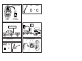
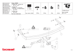
wordt niet meer gebruikt. Verwijder eventueel de plakkers op de bevestigingspunten X. Zie figuur 1.
3. Boor in de kunststof kap de gaten B ø 8mm. zie fig. 2
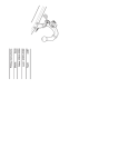
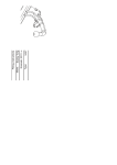
4. Plaats de trekhaak tegen het achterpaneel op de punten A.
5. Richt de trekhaak uit en draai de boutverbindingen stevig handvast.
6. Draai alle bouten en moeren overeenkomstig schets vast.
7. Indien aanwezig: Zaag het in figuur 3 aangegeven deel uit het hitteschild.
8. Monteer de kunststof kap aan de dwarsbalk van de trekhaak op de
punten B. Zie figuur 4.
19. Monteer de kogelstang inclusief stekkerplaat.
10. Draai alle bouten en moeren overeenkomstig schets vast.
11. Kit de aangegeven delen af (zie schets).
12. Monteer het verwijderde.
Raadpleeg voor demontage en montage van voertuig onderdelen het
werkplaats handboek.
Raadpleeg voor montage en bevestigingsmiddelen de schets.
BELANGRIJK:
* Voor eventueel noodzakelijke aanpassing(en) “van het voertuig” dient
men de dealer te raadplegen.
* Indien op de bevestigingspunten een bitumen of anti-dreunlaag aanwezig is, dient deze verwijderd te worden.
* Voor de max. toegestane massa, welke uw auto mag trekken, dient u uw
dealer te raadplegen.
* Bij het boren dient men er zorg voor te dragen, dat electriciteits-,
© 554470/18-04-2012/15
rem- en brandstofleidingen niet worden geraakt.
* Verwijder "indien aanwezig" de plastik dopjes uit de puntlasmoeren.
* Deze handleiding dient na montage bij de voertuigpapieren gevoegd te
worden.
* Thule is niet aansprakelijk voor de schade die het direct of indirect gevolg
is van onjuiste montage, daaronder begrepen gebruik van niet-geschikte
gereedschappen en het gebruik van andere dan de voorgeschreven
montagewijze en middelen, dan wel onjuiste interpretatie van dit onderhavig montagevoorschrift.
GB
FITTING INSTRUCTIONS:
Before you start the fitting you must check the type plate to determine which sketch, in the fitting instruction, is applicable.
1. Remove the rear-light units.
2. Remove the bumper and the steel buffer beam from the vehicle.
Remove the plastic cap from the metal bumper.The buffer beam will no
longer be needed. Remove any stickers that may be present at the
points X of attachment.See figure 1.
3. Drill the holes B (ø8mm) in the plastic cap. See fig. 2.
4. Position the tow bar against the rear panel at points A.
5. Align the tow bar and hand-tighten the bolts securely.
6. Tighten all nuts and bolts to the torque indicated in the drawing.
7. If present: Saw off the part of the heat shield denoted in figure 3.
8. Attach the plastic cap to the crossbeam of the tow bar at the points B.
See figure 4.
9. Fit the ball hitch, including socket plate.
10. Tighten all nuts and bolts to the torque indicated in the drawing.
11. Seal the portions indicated (See diagram.)
12. Fit the sections removed.
For dismantling and fitting the vehicle parts, see the site handbook.
For fitting instructions and attachment method, see drawing.
NOTE:
* Should this installation process entail the cutting of the bumper –
© 554470/18-04-2012/4