1
worden.
NL
MONTAGEHANDLEIDING:
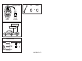
1. Demonteer de bumper inclusief de stalen stootbalk van het voertuig, de
stootbalk wordt niet meer gebruikt. Herplaats de bouten. Zie figuur 1.
2. Neem de uitlaat uit het achterste ophangrubber.
3. Demonteer het hitteschild.
4. V o o r d e s e d a n u i t v o e r i n g m e t P D C g e l d t : Verplaats de connector ±10mm naar beneden.
5. Plaats de trekhaak in het chassis.
6. Plaats de contra’s A, B en C.
7. Draai alle bouten en moeren overeenkomstig schets vast.
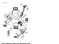
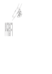
8. L e t o p a l l e e n b i j d e w a g o n g e l d t : Zaag een deel overeenkomstig
figuur 2 in het midden aan de onderzijde uit de bumper.
9. Monteer het verwijderde.
10.Monteer het kogelhuis inclusief steun.
11. Monteer de stekkerplaat.
12.Draai alle bouten en moeren overeenkomstig tabel vast.
Raadpleeg voor demontage en montage van voertuig onderdelen het
werkplaats handboek.
Raadpleeg voor montage en bevestigingsmiddelen de schets.
Raadpleeg voor montage en demontage van het afneembare kogelsysteem de bijgevoegde montagehandleiding.
GB
FITTING INSTRUCTIONS:
1. Remove the bumper and the steel buffer beam from the vehicle. The
buffer beam will no longer be needed. Replace the bolts. See figure 1.
2. Release the exhaust from the rearmost exhaust rubber.
3. Remove the heat shield.
4. F o r t h e s a l o o n m o d e l w i t h P D C t h e f o l l o w i n g a p p l i e s : move the
connector ca 10mm lower.
5. Position the tow bar in the chassis.
6. Position backplates A, B and C.
7. Tighten all nuts and bolts to the torque indicated in the drawing.
8. N . B . T h e f o l l o w i n g o n l y a p p l i e s t o t h e e s t a t e : Saw a section out
of the middle of the underside of the bumper as shown in fig 2.
9. Fit the section removed.
10.Fit the ball housing, including support.
11. Fit the socket plate.
12.Tighten all nuts and bolts to the torque indicated in the table.
BELANGRIJK:
For dismantling and fitting the vehicle parts, see the site handbook.
For fitting instructions and attachment method, see drawing.
See the assembly manual supplied for instructions on fitting the removable ball system.
NOTE:
* Voor eventueel noodzakelijke aanpassing(en) “van het voertuig” dient
men de dealer te raadplegen.
* Indien op de bevestigingspunten een bitumen of anti-dreunlaag aanwezig is, dient deze verwijderd te worden.
* Voor de max. toegestane massa, welke uw auto mag trekken, dient u uw
dealer te raadplegen.
* Bij het boren dient men er zorg voor te dragen, dat electriciteits-,
rem- en brandstofleidingen niet worden geraakt.
* Verwijder "indien aanwezig" de plastik dopjes uit de puntlasmoeren.
* Deze handleiding dient na montage bij de voertuigpapieren gevoegd te
* Should this installation process entail the cutting of the bumper –
conformation MUST be obtained by the installation engineer of the
customer’s acceptance prior to completion. Thule Towing Systems
do not accept responsibility for any matters arising as a result of
this miscommunication.
* All measurements are in mm!
* The dealer should be consulted for possible necessary adjustment(s)
"of the vehicle".
* Remove the insulating material from the contact area of the fitting
points.
© 486470MN/24-07-2007/3
Wa g o n o n l y !
Outside bumper
60
78
Middle bumper
145
70
75
Existing cut out
Cut out
55
Extra cut out
Fig.2
Edge bumper
© 486470MN/24-07-2007/12