Transcript
ENGLISH
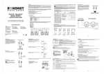
Terminal Block
Channel 1
1+2
Channel Functionality
Channel 2
Universal transmitter OR Shutter
Note: The functionality of channel 2 is
determined by dipswitch 4.
Channel
3+4
Universal transmitter
3. INSTALLING THE T72X
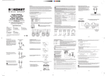
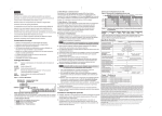
✦Step 1: Front cover removal
OFF
YES
Channel 2: Universal Mode
OFF
ON
YES
Channel 2: Shutter Mode
ON
ON
N0
Note: This definition also applies to channel 2 when the channel
is defined as Universal Transmitter (Dipswitch 4: OFF)
ON
Normally Closed (NC)
OFF*
Normally Open (NO)
Used to determine the response time for a universal transmitter.
(Channel 1)
Note: This definition also applies to channel 2 when the channel
is defined as Universal Transmitter (Dipswitch 4: OFF)
Dipswitch Position
ON
OFF*
7
Dipswitch Position
Hold Status
ON
Hold is On: There will be 2.5 minutes dead
time between the alarm detection
transmissions. (Restore messages will be
sent immiately).
Note: Only one alarm message is
transmitted in any 2.5 minute
period.
Description
Used for setting the number of pulses for a shutter detector
(channel 2 only).
OFF*
Note: If Dipswitch 4 is defined as OFF then dipswitches 1-3
will not be activated.
Dipswitch 1 Dipswitch 2 Dipswitch 3 No. of Pulses
OFF
2
OFF
OFF
OFF
4
OFF
ON
OFF
OFF
ON
6
OFF
8
ON
ON
10
OFF
ON
OFF
OFF
12
ON
ON
14
ON
ON
OFF
ON
16
ON
ON
Hold is Off: No dead time between alarm
detection transmissions (the unit transmits
after each detection).
Note: In both HOLD status thebfollowing occurs:
1. Disconnecting the detector’s input terminal will send an
alarm after 500 ms.
2. Reopening and closing the detector inputs will generate
an extra alarm and restore messages.
Set dipswitches 1-3 for the required number of pulses as
shown in the following table:
The T72X must identify itself to the system’s receiver
by writing its coded messages into the receiver’s
address memory. The receiver must identify each
channel separately. This is accomplished by
performing the following steps:
Fast: 10 ms (For operation with a
shock sensor)
Used to determine the HOLD status of a universal transmitter.
Note: This definition also applies to channel 2 when the channel
is defined as Universal Transmitter (Dipswitch 4: OFF)
After setting the transmitter/receiver communication use
the dipswitches to configure the transmitter operation as
described in the table below.
2: Transmitter/Receiver
Communication Set Up
Response Time
Slow: 500 ms (For operation with
magnetic contacts, etc.)
(Channel 1)
3: Dipswitch Settings
1-3
Response Time
Dipswitch Position
8
*
Not used.
Default
✦Step
4: Selection of the
Installation Location
a. Select a location best suited for communication quality
and near the intended wired detector (for switched sensor).
Place the unit at the highest possible position.
b. Temporarily attach the unit to this point using two sided adhesive
tape.
c. Generate an Alarm signal (by momentarily opening or closing the
input terminals) and verify that the receiver has received the signal.
If the alarm signal is not detected, reposition the T72X and try again.
LD1
Description
ON
The LED lights momentarily after each detection transmission.
Blink
SW2
Indicates LOW battery. The LED blinks after each detection transmission.
SPECIFICATIONS
ELECTRICAL
Battery Type: CR123 3V Lithium Battery
Current Consumption: 6µA standby
Frequency: 868.65 MHz
Dead Time (HOLD ON): 2.5 minutes
Supervision Transmission: Every 65 minutes
Modulation Type: ASK
Battery Life: 5 years (HOLD ON)
PHYSICAL
Size: 81 x 35 x 32 mm (3.2 x 1.37 x 1.27 in.)
ENVIRONMENTAL
RF immunity:
20V/m 80MHz to 1GHz
Operating temperature:
0°C to 55°C (32°F to 131°F)
Storage temperature:
-20°C to 60°C (-4°F to 140°F)
Specifications are subject to change without prior notice.
Should any questions arise please contact your supplier.
ISRAEL
ROKONET ELECTRONICS Ltd.
14 Hachoma St.
75655 Rishon Letzion, Israel
Tel. +972 (0)3 9616555
Fax. +972 (0)3 9616584
Email: [email protected]
UK
ROKONET UK LTD.
Tel. +44 (0)1527 576 765
Fax. +44 (0)1527 576 816
Email: [email protected]
1. DESCRIZIONE GENERALE
T72X è un trasmettitore radio supervisionato con una
doppia funzione. Il dispositivo può essere utilizzato per
controllare due contatti magnetici esterni per porte/finestre
oppure ad un contatto magnetico ed un contatto a filo per
tapparelle.
Il T72X funziona con una batteria a litio da 3 Volt ed è
compatibile con i ricevitori Rokonet che utilizzano la
frequenza di 868 Mhz.
CARATTERISTICHE DEL T72X
● Portata radio in aria libera di 400 metri
● Si programma per autoapprendimento e utilizza un codice preprogrammato selezionato in modo casuale tra 16 milioni di codici
● Controllato da Microprocessore
● Batteria al litio per una lunga autonomia
● Supervisionato per allarme, tamper, stato batteria e buon
funzionamento
● Due funzioni selezionabili: Contatti Porte/Finestre e Protezione
Tapparelle
● Conteggio impulsi selezionabili (se abilitato il controllo tapparelle)
● Tempo di risposta selezionabile e ingresso NC/NO per la funzione
controllo contatti porte/finestre
● Protezione antiapertura e antiasportazione
2. CABLAGGIO MORSETTI:
Possono essere collegati due ingressi ai morsetti del
T72X (Vedi figura 1)
Ingressi
Morsetti
Funzionamento Ingressi
Ingresso 1
1+2
Controllo porte/finestre
Ingresso 2
3+4
Controllo porte/finestre oppure Tapparelle
Nota: Il funzionamento dell’ingresso 2 è
determinato dal microinterruttore 4.
Restricted from use in Greece.
Ordering P/N:
http://www.rokonet.com
Part Number
Description
RWT72X86800A
Universal/shutter transmitter 868.65 MHz
ROKONET LIMITED WARRANTY
Rokonet Electronics, Ltd. and its subsidiaries and affiliates ("Seller") warrants its products to be free from
defects in materials and workmanship under normal use for 18 months from the date of production. Because
Seller does not install or connect the product and because the product may be used in conjunction with
products not manufactured by the Seller, Seller can not guarantee the performance of the security system
which uses this product. Sellers obligation and liability under this warranty is expressly limited to repairing
and replacing, at Sellers option, within a reasonable time after the date of delivery, any product not meeting
the specifications.
Seller makes no other warranty, expressed or implied, and makes no warranty of merchantability or of
fitness for any particular purpose. In no case shall seller be liable for any consequential or incidental
damages for breach of this or any other warranty, expressed or implied, or upon any other basis of liability
whatsoever.
Sellers obligation under this warranty shall not include any transportation charges or costs of installation
or any liability for direct, indirect, or consequential damages or delay.
Seller does not represent that its product may not be compromised or circumvented; that the product will
prevent any persona; injury or property loss by burglary, robbery, fire or otherwise; or that the product will
in all cases provide adequate warning or protection.
Buyer understands that a properly installed and maintained alarm may only reduce the risk of burglary,
robbery or fire without warning, but is not insurance or a guaranty that such will not occur or that there will
be no personal injury or property loss as a result.
Consequently seller shall have no liability for any personal injury, property damage or loss based on a claim
that the product fails to give warning. However, if seller is held liable, whether directly or indirectly, for any
loss or damage arising from under this limited warranty or otherwise, regardless of cause or origin, sellers
maximum liability shall not exceed the purchase price of the product, which shall be complete and exclusive
remedy against seller.
No employee or representative of Seller is authorized to change this warranty in any way or grant any other
warranty.
T72X: Shutter / Double
Door Transmitter
WARNING: This product should be tested at least once a week.
OFF
OFF
SI
Ingr. 2: Modo porte/finestre
OFF
ON
SI
2: Comunicazione
Trasmettitore/Ricevitore
Il T72X deve essere registrato nella memoria del
ricevitore tramite la comunicazione di un indirizzo nel
modo WRITE (trasmissione INDIRIZZO). Svolgere
l’operazione come di seguito illustrato:
ON
Ingr. 2: Modo tapparelle
ON
ON
NO
OFF*
5
Posizione Microint.
7
Normalmente Chiuso (NC)
OFF*
Normalmente Aperto (NO)
Usato per determinare il tempo di risposta dell'ingresso in
modalitàcontrollo porte/finestre (Ingresso 1)
Posizione Microint.
Tempo di Risposta
ON
Lento: 500 ms (funzionamento con
contatti magnetici, etc.)
OFF*
Veloce: 10 ms (funzionamento con
sensori inerziali)
Usato per determinare lo stato HOLD (blocco trasmissioni) in
modalità controllo porte/finestre (Ingresso 1)
Posizione Microint.
Stato HOLD
Hold On: Blocco trasmissioni per 2.5 minuti
ON
F. Verificare che il ricevitore abbia registrato ogni
ingresso generando un segnale di allarme (aprendo e
chiudendo momentaneamente i morsetti di ogni
ingresso).
tra due attivazioni di allarme (il messaggio di
ripristino viene comunque sempre trasmesso
al verificarsi dell'evento).
Nota: Solo un messaggio di allarme
verrà trasmesso in un periodo
di 2.5 minuti.
3: Impostazione
Microinterruttori:
Nota: Si consiglia di abilitare questa
funzione SOLO quando si
utilizzano dei sensori inerziali.
Dopo aver predisposto la comunicazione tra
trasmettitore/ricevitore usare i microinterruttori per
configurare il funzionamento del trasmettitore come
descritto nella tabella sotto.
OFF*
8
Descrizione
Usati per impostare il numero di impulsi per un contatto a filo per
tapparelle (solo ingresso 2).
Impostare i microinterruttori da 1 a 3 per il numero
di impulsi richiesto come mostrato nella tabella seguente:
Microint. 1
Microint. 2
Microint. 3
OFF
ON
OFF
ON
OFF
ON
OFF
ON
OFF
OFF
ON
ON
OFF
OFF
OFF
OFF
OFF
OFF
ON
ON
ON
ON
ON
ON
Modo di funzionamento Ingresso
ON
Nota: Questa impostazione è anche applicabile all'ingresso 2
quando è utilizzato nella modalità controllo porte/finestre
(Microinterruttore 4: OFF)
E. Predisporre il ricevitore nel modo normale di
funzionamento.
1-3
Usato per determinare il funzionamento dell'ingresso in modalità
controllo porte/finestre (Ingresso 1)
Nota: Questa impostazione è anche applicabile all'ingresso 2
quando è utilizzato nella modalità controllo porte/finestre
(Microinterruttore 4: OFF)
D. Per programmare l’indirizzo dell’ingresso 2 impostare
i microinterruttori 4 e 5 in funzione dell’applicazione
richiesta e trasmettere un Messaggio WRITE
premendo e tenendo premuti entrambi i tamper per
almeno 3 secondi.
Microinterruttore
N.
Controllo Porte/Finestre
Nota: Questa impostazione è anche applicabile all'ingresso 2
quando è utilizzato nella modalità controllo porte/finestre
(Microinterruttore 4: OFF)
* Predisposizione di fabbrica.
✦ Fase
Controllo contatto a filo per tapparelle
Nota: Usare i microinterruttori da 1 a 3
per determinare il n. di impulsi.
6
Nota: Se il microinterruttore 4 è impostato su OFF, i
microinterruttori da 1 a 3 non saranno utilizzati.
✦ Fase
Posizione Microint. Modo di funz. ingresso 2
Microint. 4 Microint. 5 Ripristino
Ingresso
Ingr. 1: Modo porte/finestre *
Usato per determinare il funzionamento dell'ingresso 2.
N. di Impulsi
2
4
6
8
10
12
14
16
Hold Off: Nessun tempo di attesa tra due
attivazioni di allarme (il dispositivo trasmette
ogni rilevazione).
Non usato.
* Predisposizione di fabbrica.
✦ Fase
4: Scelta della posizione
di installazione
a. Scegliere un buon punto di installazione per garantire una
buona qualità di comunicazione radio, vicino al rilevatore da
collegare all’ingresso dell’unità.
Installare il trasmettitore quanto più in alto possibile.
b. Fissare temporaneamente l’unità tramite del nastro biadesivo.
c. Generare un segnale d’allarme (aprendo o chiudendo
l’ingresso dell’unità) e verificare al ricevitore se il segnale è
stato correttamente ricevuto. Se l’allarme non è stato ricevuto
posizionare il tramettitore in un punto diverso e riprovare.
✦ Fase
5INT72X
07/03
5: Montaggio Finale
fig. 2
Separare la parte posteriore del tramettitore dall’elettronica
(fig. 4), fissare il contenitore e rimontare tutte le parti dell’unità
(fig. 5) collegando il sensore all’ingresso del trasmettitore.
4. INDICAZIONI A LED
Condizione
Descrizione
Acceso
Il LED si accende per qualche secondo dopo ogni rilevazione.
Lampegg.
Indica una condizione di basso livello batteria. Il LED lampeggia per 3 volte
durante ogni trasmissione.
a
b
SPECIFICHE TECNICHE
ELETTRICHE
Tipo Batteria:
CR123 3V al Litio
Assorb. Corrente:
6µA a riposo
Frequenza:
868.65 MHz
Inibizione Trasmissioni: 2.5 minuti
Supervisione:
Ogni 65 minuti
Tipo di Modulazione: ASK
Durata Batteria:
5 anni (con inibiz. trasmissioni abilitata)
FISICHE
Dimensioni:
81 x 35 x 32 mm
AMBIENTALI
Immunità RF:
20V/m 80MHz to 1GHz
Temp. Operativa:
da 0°C a 55°C
Temp. di Stoccaggio: da -20°C a 60°C
Le caratteristiche tecniche sono soggette a variazioni senza
l'obbligo di preavviso.
Per qualsisi informazione contattare il proprio rivenditore.
Come Ordinare:
Cod. Prodotto
fig. 3
Descrizione
RWT72X86800A Trasmettitore Universale/Tapparelle 868.65 MHz
GARANZIA LIMITATA ROKONET
Rokonet Electronics, Ltd. and its subsidiaries and affiliates ("Seller") warrants its products
to be free from defects in materials and workmanship under normal use for 18 months
from the date of production. Because Seller does not install or connect the product and
because the product may be used in conjunction with products not manufactured by the
Seller, Seller can not guarantee the performance of the security system which uses this
product. Sellers obligation and liability under this warranty is expressly limited to repairing
and replacing, at Sellers option, within a reasonable time after the date of delivery, any
product not meeting the specifications.
Seller makes no other warranty, expressed or implied, and makes no warranty of
merchantability or of fitness for any particular purpose. In no case shall seller be liable
for any consequential or incidental damages for breach of this or any other warranty,
expressed or implied, or upon any other basis of liability whatsoever.
Sellers obligation under this warranty shall not include any transportation charges or costs
of installation or any liability for direct, indirect, or consequential damages or delay.
Seller does not represent that its product may not be compromised or circumvented; that
the product will prevent any persona; injury or property loss by burglary, robbery, fire or
otherwise; or that the product will in all cases provide adequate warning or protection.
Buyer understands that a properly installed and maintained alarm may only reduce the
risk of burglary, robbery or fire without warning, but is not insurance or a guaranty that
such will not occur or that there will be no personal injury or property loss as a result.
Consequently seller shall have no liability for any personal injury, property damage or
loss based on a claim that the product fails to give warning. However, if seller is held
liable, whether directly or indirectly, for any loss or damage arising from under this limited
warranty or otherwise, regardless of cause or origin, sellers maximum liability shall not
exceed the purchase price of the product, which shall be complete and exclusive remedy
against seller.
No employee or representative of Seller is authorized to change this warranty in any way
or grant any other warranty.
WARNING: This product should be tested at least once a week.
fig. 4
NET 1998
Rimuovere il coperchio anteriore come descritto in
Figura 2
4
BRAZIL
ROKONET BRASIL LTDA.
Tel. +55 21 2496 3544
Fax. +55 21 2496 3547
Email: [email protected]
© ROKO
3. INSTALLAZIONE DEL T72X
✦ Fase 1: Rimozione del coperchio
anteriore
A. Predisporre il ricevitore nel modo WRITE (Seguire
le istruzioni del ricevitore).
B. Rimuovere la batteria dalla sua plastica e inserirla
nel trasmettitore, facendo attenzione alla polarità.
(Vedi figura 3).
C. Trasmettere un messaggio WRITE (Indirizzo) per
ogni ingresso. Usare i microinterruttori 4 e 5 per
scegliere l’ingresso 1 o 2, come descritto nella
tabella sotto. Tutti gli altri microinterruttori devono
essere in posizione OFF. Per programmare
l’indirizzo dell’ingresso 1 impostare i
microinterruttori 4 e 5 nella posizione OFF e
trasmettere il Messaggio WRITE premendo e
tenendo premuti entrambi i tamper per almeno 3
secondi.
ITALY
ROKONET ELECTRONICS SRL
Tel. +39 02 392 5354
Fax. +39 02 392 5131
Email: [email protected]
USA
ROKONET IND. USA INC.
Tel. +1 914 592 1068
Fax. +1 914 592 1271
Email: [email protected]
© Rokonet Electronics Ltd.
ITALIANO
BATTERY
+
4. LED INDICATION
Condition
(Channel 1)
6
Dipswitch
No.
Universal Transmitter
Used to determine an external sensor mode for a universal
transmitter.
5
D. To program the ID of channel 2 set dipswitches 4 and
5 according to the required application and send a
Write message by pressing both tamper buttons for at
least 3 seconds.
E. Set the receiver to the Normal mode.
F. Verify that the receiver has identified each of the
channels by generating an alarm signal (by
momentarily opening and closing the input terminal of
each channel).
Remove the front cover as described in Figure 2.
✦Step
OFF*
*Default
✦Step
ANT2
SW1
Note: Use dipswitches1-3 to determine
the number of pulses.
Restore
OFF
Shutter Control
Separate the back part of the transmitter (fig. 4), and mount all the
parts in place (fig. 5). If relevant, connect the sensor to the input
terminals.
For shutter protection see fig. 1
Per la configurazione Tapparellle vedere la fig. 1
DIPSWITCH
8 7 6 54 3 2 1
Two channels can be connected to the terminal block of
the T72X (See figure 1)
ON
Channel 2 operation mode
5: Final Mounting
ON
2. TERMINAL BLOCK WIRING
Dipswitch 4 Dipswitch 5
Channel
Channel 1: Universal Mode*
Dipswitch position
✦Step
CH2 CH1
4 3 2 1
The T72X is a dual function supervised transmitter that can be
connected to two separate external contacts (universal protection)
OR to one external contact (universal protection) and one shutter
contact protection.
The T72X operates with Rokonet’s receivers and is powered by
a 3-volt lithium battery.
T72X FEATURES
● Operates up to 1333ft (400m) range (outdoors)
● Uses one of more than 16 million pseudo-randomly selected
preset coded addresses for setup (no DIP switches )
● Microprocessor design
● Extended battery life
● Fully supervised
● Selective function (universal or shutter protection)
● Selective pulse counter (for shutter control function)
● Selective response time and input (NO/NC) for universal
control function
● Back and cover tamper protection
Used to determine channel 2 functionality.
4
-
1. GENERAL DESCRIPTION
A. Set the receiver to the Write Mode (Follow the receiver’s
instructions).
B. Remove the battery from the insulation material and
reinsert it into the transmitter, paying attention to the
polarity. (See Figure 3).
C. Send a separate Write message to each channel.
Use Dipswitches 4 and 5, as described in the table
below, to choose a channel. All other dipswitches
must be in OFF position. To program the ID of channel
1 set the dipswitches to the OFF position and send a
Write message by pressing both tamper buttons for at
least 3 seconds.
98
© RO
KO
T 19
NE
fig. 5