1
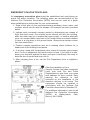
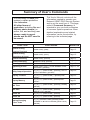
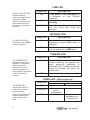
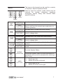
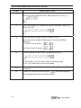
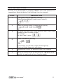
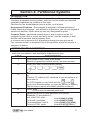
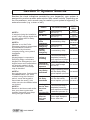
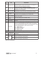
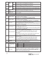
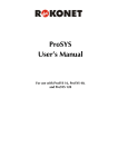
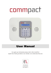
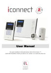
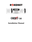
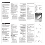
RP296MUD User's Manual TE D U L L I SS A C L A ST E M SYS RP296MUD User’s Manual Customer Information 1. The ORBIT-PRO(Model RP-296) complies with FCC Part 68 Rules. On the upper panel of this product is a label that contains, among other information, the FCC Registration Number and Ringer Equivalence Number (REN is 0.8B). If requested, this information must be provided to the Telephone Company. 2. An FCC compliant telephone connector is provided with this equipment. This equipment is designed to be connected to the telephone network or premises wiring using a connector, which is Part 68 compliant. 3. If the ORBIT-PRO(RP-296) is not operating properly, it may cause harm to the telephone network. If so, the Telephone Company will notify you in advance that a temporary discontinuance of service may be required. If advance notice is not practical, you will be notified as soon as possible. Also, you will be advised of your right to file a complaint with the FCC if it is necessary. 4. The Telephone Company may make changes in its facilities, equipment, operations, or procedures, which could affect the operation of the equipment. If this happens, the Telephone Company will provide advance notice in order to enable you to make the necessary modifications to maintain uninterrupted service. If the equipment is causing harm to the telephone network, the Telephone Company may request that the equipment be disconnected until the problem is resolved. 5. Connection to telephone company-provided coin service is prohibited. Connection to party line service is subject to state tariffs. 6. If trouble is experienced with the ORBIT-PRO(RP-296), for repair and warranty information, please contact your supplier. For service centers please see back cover. FCC Warning This equipment has been tested and found to comply with the limits for a Class B digital device pursuant to Part 15 of the FCC Rules. These limits are designed to provide reasonable protection against harmful interference in a residential installation. This equipment generates, uses, and can radiate radio frequency energy and, if not installed and used in accordance with the instructions, may cause harmful interference to radio communications. However, there is no guarantee that interference will not occur in a particular installation. If this equipment does cause harmful interference to radio or television reception, which can be determined by turning the equipment off and on, the user is encouraged to try to correct the interference by one or more of the following measures: x Reorient or relocate the receiving antenna. x Increase the separation between the equipment and the receiver. x Connect the equipment into an outlet on a circuit different from that to which the receiver is connected. x Consult the dealer or an experienced Radio/TV technician for help. Changes or modifications to this unit not expressly approved by Rokonet, Ltd., could void the user's authority to operate the equipment. p/n: 5IN296UMUL B EMERGENCY EVACUATION PLANS An emergency evacuation plan should be established and used during an actual fire alarm condition. The following steps are recommended by the National Fire Protection Association (NFPA) and can be used as a guide when establishing a similar plan for your circumstances. 1. Draw a floor plan of your premises showing windows, doors, stairs, and rooftops, which can be used for escape. An example has been provided below. 2. Indicate each occupant's escape routes by determining two means of flight from each room. One should be the normal exit from the building, while the other may be a window that opens easily, or another alternate route. An escape ladder may have to be located near an escape window if there is a long drop to the ground below. Always keep escape routes free from obstruction. 3. Practice escape procedures and set a meeting place outdoors for a headcount of the building's occupants. 4. In a home, sleep with the bedroom door closed to increase your escape time. If a fire is suspected, first test the door for heat. If you think it is safe, brace your shoulder against the door and open it cautiously. Be ready to slam the door if smoke and heat rush in. 5. After escaping from a fire, call the Fire Department from a neighbor's phone. After the installation of your Security System has been completed, notify your local Fire and Police Departments to give them your name and address for their records. Early warning fire detection is best achieved by the installation of fire detection devices in all rooms. This equipment should be installed in accordance with the National Fire Protection Association's Standard 72. For additional information, write to the National Fire Protection Association (NFPA) at Batterymarch Park, Quincy, MA 02289. Summary of User’s Commands It is necessary to ARM your system to obtain protection from intrusion. All other forms of protection, including fire and 24-hour panic alarms (i.e. police, fire, and auxiliary) are always ready to report alarms and do NOT need to be armed. FUNCTION System Arming This User's Manual contains all the information needed to operate your Rokonet ORBIT-PRO Security System and to get the most from it. This page, called a Command Summary, is intended to give you brief summaries of common system operations. More detailed explanations and related information can be found within, by referring to the indicated page. PROCEDURE MORE ON [USER CODE] [ARM] Page 12 [USER CODE] [STAY] Page 12 System Disarming [USER CODE] [ENTER] Page 15 Duress Disarming [DURESS CODE] [ENTER] Page 16 Silencing an Alarm [USER CODE] [ENTER] Page 15 Bypassing a Zone [USER CODE ] [ BYP ] [ ZONE NUMBER TO BE BYPASSED ] [ENTER] Page 13, 20 Utility Output Operation [ ] [ 2 ] [ 1 ] [USER CODE ] [ENTER] [ UTILITY OUTPUT NUMBER ] [ENTER] Display Troubles [ ] [ 3 ] [ 1 ] [USER CODE ] + [ENTER] AND SCROLL Display Memory [ ] [ 3 ] [ 5 ] [USER CODE ] [ENTER] AND SCROLL Edit Time [ ] [ 6 ] [ 1 ] [USER CODE ] [ENTER] [HH:MM] [ENTER] Edit Date [ ] [ 6 ] [ 2 ] [USER CODE ] [ENTER] [MM:DD:YYYY] [ENTER] Chime On [ ] [ 4 ] [ 4 ] [USER CODE ] [ENTER] Page 21 Chime Off [ 4 ] [ 3 ] [USER CODE ] [ENTER] Page 21 (Leaving Premises) System Arming (Remaining at Home) Setting/Changing a User Code Page 20 Page 23 Page 21 Page 22 Page 22 [] [] [ 5 ] [MASTER CODE] [ENTER] [CODE NUMBER TO BE SET/CHANGED] [NEW CODE] [ENTER] Page 10 Table of Contents SECTION 1: LET’S GET ACQUAINTED.......................................... 1 INTRODUCTION ................................................................................. 1 SOME DEFINITIONS ........................................................................... 2 Zone ........................................................................................... 2 24-Hour Zone ............................................................................. 2 Central Stations .......................................................................... 2 Chimes ....................................................................................... 2 Trouble Reporting....................................................................... 2 Utility Outputs ............................................................................. 2 Key-switch .................................................................................. 2 Arming Your System .................................................................. 2 Full Arming and Home Arming ................................................... 3 Quick Arming and Code Arming................................................. 3 Entry/Exit Delays ........................................................................ 3 Arming with the Front Door Open............................................... 3 Follow me ................................................................................... 3 Scheduling.................................................................................. 3 Partitions..................................................................................... 3 System Expansion..................................................................... 3 SECTION 2: YOUR KEYPAD ........................................................... 4 VISUAL INDICATORS .......................................................................... 4 KEYS ............................................................................................... 7 SECTION 3: OPERATING YOUR SYSTEM..................................... 8 EMERGENCY KEYS ........................................................................... 8 Police Emergency....................................................................... 8 Fire Emergency .......................................................................... 8 Auxiliary Emergency................................................................... 8 USER CODES ................................................................................... 9 SETTING/CHANGING ACCESS CODES......................................... 10 DELETING USER CODES ................................................................. 11 ARMING YOUR SYSTEM .................................................................. 12 ZONE BYPASSING ........................................................................... 13 BYPASSING/ UNBYPASSING A ZONE(S) ........................................... 13 VIEW (NOT READY ZONE STATUS) .................................................... 14 user manual a DURESS DISARMING ....................................................................... 16 DISARMING BY USING THE DURESS CODE....................................... 16 SECTION 4: PARTITIONED SYSTEMS......................................... 17 INTRODUCTION ............................................................................... 17 ARMING MULTIPLE PARTITIONS ....................................................... 17 DISARMING MULTIPLE PARTITIONS .................................................. 18 SECTION 5: SYSTEM SOUNDS .................................................... 19 SECTION 6: USER FUNCTIONS ................................................... 20 SECTION 7: SYSTEM TROUBLES................................................ 23 b user manual Section 1: Let’s Get Acquainted INTRODUCTION LED KEYPAD Congratulations on your purchase of Rokonet’s ORBIT-PRO Security System. The ORBIT-PRO has been specifically designed to meet a wide range of security needs for many residential and commercial applications. You communicate with your ORBIT-PRO through its keypad(s). There are two types of keypads: one with LEDs display, and the other with LCD display. Using its keys, you can issue commands to your system. In turn, the system can communicate information to you via its display, indicators and by the sounds it makes. LCD KEYPAD Your ORBIT-PRO security system also consists of a variety of sensors, detectors, and contacts placed throughout the premises and designed to recognize abnormal conditions. Typically, your system protects against intrusion. Some systems may also have fire protection or environmental protection (such as gas or water level sensors) All of your system's detectors, sensors, and contacts are wired to the control panel. As such, your system always knows the status of any protected door, window, hallway, room, or area. Similarly, it knows if a smoke detector has been activated. The control panel, which contains the system's electronics and backup battery, functions in the background and, for purposes of security, is installed out of sight. user manual 1 SOME DEFINITIONS There are a few terms with which you should become familiar. Knowing them will help you to better understand and use your system Zone A single detector, or group of detectors, usually relating to a certain area of the premises or type of protection. Zones that use devices designed to detect break-ins are called intrusion zones. Another kind of zone may contain one or more Smoke Detectors. Such zones are called fire zones. An environmental zone typically protects the premises from gas leaks and/or flooding. 24-Hour Zone A 24-Hour intrusion zone is always armed and is usually assigned to openings, which should never be disturbed-like fixed glass and non-movable skylights. Central Stations Your system is set up to report alarms to a Central Station–a facility which continually monitors the activities of many security systems, usually via the telephone network, and dispatch the proper authorities. Chimes The chime is a series of short keypad tones, which can be set up to annunciate, during the disarmed period, the violation of selected intrusion zone(s). The chime tone can be used to annunciate the arrival of a customer each time the front door opens. The chime can be disabled or enabled at your discretion. Trouble Reporting If desired, your security system may also report to the Central Station any troubles or malfunctions it senses, so that a service call can be made. Utility Outputs In addition to your system's normal operation, it's possible to place a household appliance or premises lighting under the control of the ORBITPRO where it can be conveniently turned on and off automatically, or by User command from any system keypad Key-switch Your system may also be equipped with a keyswitch, useful for simple arming and disarming operations - usually at a remote location. Arming your system enables its intrusion detectors to trigger an alarm when violated. Remember, fire protection and the protection offered by the keypad's emergency keys are always armed and always available Arming Your System 2 user manual Secured or Bypassed Before you arm your system, all of its zones must either be secured or bypassed. Full Arming and Home Arming Your ORBIT-PRO offers two kinds of system arming. Full Arming prepares all of the system's intrusion detectors to sound an alarm, if violated, Home Arming (or Stay Arming) allows individuals to remain inside and move about the premises even after the system is armed Quick Arming and Code Arming Entry/Exit Delays Your ORBIT-PRO also offers two methods of arming. Quick Arming achieves the result with just the press of a single key (either or ). Code Arming requires that a valid Master Code or User Code be entered first. Your security system must incorporate an Entry/Exit Delay to allow proper entry and exit to and from the premises without causing inadvertent alarms. Arming with the Front Door Open If set up by your alarm company, the ORBIT-PRO allows you the convenience of arming your system with the front door open. After which you must close the door as you leave the premises. With such a door open (and all other zones secure), the system is considered "ready to arm"; the Zone LED corresponding to the opened door will be lit, and the keypad's READY LED will flash. Follow me In addition to the standard alarm reporting to the Center Station, the system can generate alarm tones to a designated system user. Scheduling Through the use of the system's built-in clock, it's possible to schedule automatic operations including arming and disarming. Partitions One of the ORBIT-PRO advantages is its ability to divide any system into a number of partitions. Think of each partition as a separate security system that can be armed and disarmed individually. System Expansion As your needs grow, your system can be readily expanded by adding modules, up to 96 zones, 16 keypads, and 33 utility outputs (to operate lights, cameras, etc.) without changing the main system. user manual 3 Section 2: Your Keypad VISUAL INDICATORS Each keypad in your system reports its status via its LED (lighted) indicators at the right. Through its keys, you can enter commands to "arm" and "disarm" the system, bypass intrusion zones, report emergencies, etc. NOTE: The keys and the LED indicators (except the Zones LED indicators) are the same in both types of keypads. As a user of your security system, you'll need to be primarily concerned with the keypad. This section discusses the keypad's visual indicators and the use of its keys. The five LED indicators found at the upper right provide typical system indications, as discussed below and on the next page. Some indicators have additional functions, explained later on. POWER LED The POWER LED is a useful indicator reflecting the system's operation. NOTE: If a trouble condition exists, the POWER LED will flash only when the system is in its disarmed state. Once the system is armed, a previously flashing POWER LED will light steadily. CONDITION (see note at left) ON OFF RAPID FLASH (about 4 times per second) SLOW FLASH (About once every 2 second) 4 EXPLANATION The system is operating properly from commercial (AC) power; its backup battery is in good condition The system is inoperative due to lack of power (from both commercial AC and backup battery); servicing will be required Indicates a trouble condition; for more information, see Section 6: System Troubles. Indicates the system is in the User Functions mode (see Section 5 for more information on User Functions) user manual ARM LED The ARM LED indicates whether or not the system's intrusion detectors are armed. CONDITION EXPLANATION ON The system's intrusion detectors are armed; subsequent violations of a protected point or area (e.g. a door, a window, unauthorized motion) will result in a burglar alarm The intrusion function of the system is disarmed OFF SLOW FLASH indicates the system is in its Exit Delay period (About once every 2 sec.) RAPID FLASH (about 4 times per second) Indicates alarm condition, and occurs after disarming alarmed system during the display in alarm memory mode. To restore the display to normal, press READY LED The READY LED indicates whether or not the system's intrusion zones are secured and ready to be armed. CONDITION EXPLANATION ON All intrusion zones are secure; the system is ready to be armed One or more intrusion zones are not secure and the system is not ready to be armed; before the system can be armed, the condition must be addressed Indicates the system is ready to be armed while a specially designated entry/exit door remains open, and when a forced arm zone is open. OFF SLOW FLASH (About once every sec.) user manual 5 FIRE LED When lit, the FIRE LED indicates that the system is experiencing a fire alarm. When flashing, a problem has been detected on the fire circuit, and must be serviced. CONDITION EXPLANATION ON A fire alarm or fire emergency is in progress or has recently occurred All fire zones are operating normally A problem has been detected on the fire circuit and must be serviced. OFF FLASHING BYPASS LED The BYPASS LED is normally lit when STAY mode is selected CONDITION EXPLANATION ON At least one intrusion zone is bypassed, or when STAY mode is selected All zones are operating normally and the system is in ARM mode. OFF TAMPER LED The TAMPER LED indicates that a zone, a keypad or an external module has been tampered with, and requires resetting. In some cases a technician code is required to restore. CONDITION EXPLANATION ON A zone, keypad, or an external module used by the system has been physically disturbed or tampered with. If disarmed without fixing the problem, will silent the sound only. All zones are operating normally OFF ZONE LED ( LED keypad only) CONDITION The ZONE LEDs indicate the status of each of the system’s intrusion zones. FOR LCD KEYPAD the display indicates the zone's number and label. 6 OFF FLASHING ON EXPLANATION SYSTEM DISARMED SYSTEM ARMED The corresponding zone is secured The indicated zone is not secured N/A N/A An alarm has occurred on the indicated zone user manual The keys on the keypad can be used for a variety of functions. Each is explained below: Used to input the numeric codes which may be required for arming, disarming, triggering emergency alarms, along with several other special functions KEYS NORMAL OPERATION USER FUNCTIONS NORMAL OPERATION USER FUNCTIONS NORMAL OPERATION USER FUNCTIONS NORMAL OPERATION USER FUNCTIONS Used to enter the User Functions mode Used to exit from the current menu and return to normal operation. Activates AWAY mode and Quick Arming. Used to change data. Activates the STAY mode and Quick Arming Used to change data. Used to disarm the system after the User Code is entered Terminates commands and confirms data to be stored Provides System Status. NORMAL OPERATION USER FUNCTIONS user manual To perform bypass, and to provide information on bypassed zones (must be pressed after entering a User Code). Scrolls up a list Moves the cursor to the left Scrolls down a list Moves the cursor to the right 7 Section 3: Operating Your System In this section, you'll learn how to perform most of the functions needed to properly operate your ORBIT-PRO and to get the most out of your security system. EMERGENCY KEYS Your keypad provides three sets of keys, which can be pushed at any time the police, fire department, or auxiliary assistance is required. Police Emergency Pressing and simultaneously, and for at least two seconds, will activate a Police Emergency alarm (Panic alarm). Fire Emergency Pressing and simultaneously, and for at least two seconds, will activate a Fire Emergency alarm. Auxiliary Emergency Pressing and simultaneously, and for at least two seconds, will activate an Auxiliary Emergency. The annunciation that results during these emergency alarms, along with other system sounds, is covered in Section 4. If your system has been programmed to do so, it will communicate any or all of these alarms to the Central Station monitoring your installation. System programming also determines whether these emergency alarms will be audible and/or capable of being communicated to the Central Station. Keyswitches If your system is equipped with a special keyswitch, it can, with the twist of a key, be toggled through ARM (Away) and DISARM modes. Note: Hidden Display It is desired for some systems, that the keypad will not display the status of the system. (If set in this mode) the ARM, READY & BYPASS LEDS will not function and the LCD display Enter code: After entering a valid user code the system will work and display the normal mode. One minute after the last operation, the system will automatically switch to the Hidden Display Mode. 8 user manual USER CODES AUTHORITY GRAND MASTER All operations for all partitions. MANAGER Same as above, except changing the Grand Master Code. MASTER Same as for Manager, but limited to designated partitions. USER Only basic operations to one or more partitions. ARM ONLY Arming one or more partitions. MAID Used only for one-time arming and disarming, after which the code is automatically erased and should be re-defined. user manual To perform many of the ORBIT-PRO's functions, a security code (often called a User Code) must be entered at the keypad. Each individual using the system is assigned a User Code, which, in turn, is linked to an Authority Level. Those with a "higher authority" have access to a greater number of system functions, while those with a "lower authority" are more restricted in what they may do. There are six different Authority Levels available for users of the ORBIT-Pro. Note that the User Codes having the lower Authority Levels (i.e. User, Arm Only, and Maid) may have variable lengths up to the chosen Code Length. A user code can have up to 6 digits. Your ORBIT-Pro can support up to 99 different User Codes, identified with index numbers from "00" through "98". Your ORBIT-PRO was given a Grand Master Code of 1–2–3–4 during manufacturing. Unless your alarm company has already changed it to suit your preference, it's best to modify this code to one which is unique and personalized. To change the Master Code, and/or to set up User Codes, follow the steps on the next page. 9 SETTING/CHANGING ACCESS CODES STEP DESCRIPTION 1 The system must be disarmed). Enter the User Functions Mode (4) and select Codes (5): 2 Enter the 4-digit (or 6) Master (or higher authority) Code, and press [ENTER] 3 Enter the two digit User Index number 00 to 98 Note: the index number 00 belongs to the Grand Master Example: For User Code 6, press For User Code 12, press 4 Carefully enter the new code and press [ENTER] If successful, you will hear a single confirming beep. If not, you'll hear three quick error beeps; 5 6 Repeat steps 3 and 4 for additional codes until complete. When all codes are entered press key twice quickly to reset and exit user function mode. 10 user manual DELETING USER CODES At times, it may be desirable to completely delete a User Code. Note that it is impossible to delete the Master Code (although it can be changed). STEP DESCRIPTION 1 The system must be disarmed. Enter the User Functions Mode (4) and choose Codes (5): 2 Enter the current Master Code and press [ENTER]: 3 To delete any other User Code, enter the User Code's index number you wish to delete (2-digit), for example: for User Code 6, press 4 Press 0 followed by [ENTER] If successful, you will hear a single confirming beep. If not, you'll hear three quick error beeps 5 6 Repeat steps 3 and 4 for additional codes until complete. When all required codes are deleted press key twice quickly to reset and exit user function mode. user manual 11 ARMING YOUR SYSTEM STEP 1 2 3 DESCRIPTION Check the READY LED on your keypad. If lit or flashing, the system is READY. If NOT lit or flashing, the system is NOT ready to be armed. Secure or bypass the violated zone(s) and then proceed. Choose among one of the following arming types: Arming when Leaving the Premises Empty: Enter your User Code and press [ARM] key NOTE: If you make a mistake the keypad will produce three short beeps. If so, press (44) quickly and re-enter the above sequence correctly 4 3 . If your system has Quick Arming, simply press All persons are to exit except the person arming the system. Leave the premises and close the door. The keypad will beep as counts down the Exit Delay period, and the ARM LED flashes for the above duration, and than light steadily. If LCD KP is in use, its display will indicate the remaining Exit Delay time, at the end of this period, it displays ARMED. Arming with the Premises Occupied Enter your User Code and press [STAY] key . If your system has Quick Arming, simply press Note: Pressing [STAY] twice will cancel the entry delay time. Pressing [4] during exit time will silence the beeps on the keypad. 4 If required, leave the premises and close the door. The keypad will beep as it counts down the Exit Delay period, and the ARM LED flashes for the above duration will than light steadily. The BYPASS LED will light, indicating that the interior zones are being bypassed. If LCD keypad is in use, its display will indicate the remaining Exit Delay time, and at the end of this period, it displays AT HOME ARMED. 12 user manual ZONE BYPASSING Warning: A bypassed zone may reduce the system's security capability. When an intrusion zone is not secured, the keypad's READY LED will not light nor can the system be readily armed. It may be convenient to have one (or more) of the zones in your installation bypassed–and thus ignored by your system. BYPASSING/ UNBYPASSING A ZONE(S) STEP 1 DESCRIPTION If the system is not ready, identify the violated zone as follow: For LED KP - the above zone(s) is identified by noting which zone LED(s) are flashing at the keypad's ZONES area. For LCD KP – Enter user code followed by to identify the violated zone(s), (scroll Up and Down with arrow keys to view all Not ready zones) 2 To bypass such a zone(s) and cause it to be ignored by the system: Enter your [code] and press ( Bypass LED will be lit) Note: If you make a mistake when entering your User Code, the keypad will produce three short beeps. Re-enter if necessary. 3 Enter the two digit zone number from 01 to 96 Repeating the zone number will un-bypass it (toggle action) An additional zone(s) can be bypassed at the same time by adding its two-digit number to the sequence. 4 When done, press . Note: all zones will be automatically un-bypassed when the panel is armed and then disarmed again. Bypass LED will turn off when arming in AWAY mode. Example: To bypass zones 2 and 13 using code 1234 Enter- 1-2-3-4 [BYP] 02 13 [ENTER] To un-bypass zone 2 only using code 1234 Enter – 1-2-3-4 [BYP] 02 [ENTER] user manual 13 VIEW (NOT READY ZONE STATUS) If the system is not ready to arm, there is at least one zone that is not secured. For LED Keypad the numbers corresponding to any unsecured zone will be illuminated and flashing on the LED ZONES area. For LCD Keypad, proceed with the following: STEP DESCRIPTION 1 Enter your User Code and press Note: the keypad will display “Not ready” zones that belong to this user code only. 2 Quick view Scroll the list Up and Down with arrow keys (STAT and BYP) to view the Not-ready zones' status. With Quick view, it's possible to view any Not ready zone(s) that is assigned to this keypad (only) without the need to first enter a User Code Just press 14 and scroll the list. user manual DISARMING AN ARMED SYSTEM AND/OR SILENCING AN ALARM STEP DESCRIPTION 1 If outside the premises, open an "entry" door. The keypad(s) will beep—indicating that the Entry Delay period has begun. 2 Disarming an armed system Before the Entry Delay expires, Enter your User Code and press . NOTE: If you make a mistake when entering your User Code, the keypad will produce three short beeps. If so, re-enter the above sequence correctly. Silencing an alarm 2 Observe the keypad. If any of the following conditions is evident, an alarm has occurred: For LED KP: ·x The ARM LED is flashing. ·x A Zone LED is lit steadily. ·x The FIRE LED is lit steadily. For LCD KP: the ARM LED is flashing, and the display will show the disturbed zone Enter your User Code and press . If an alarm occurred, the ARM LED and the corresponding zoneLED will flash for Alarm memory period of about 60 sec. If using LCD keypad scroll through the list of alarmed zones To exit alarm memory before timeout expired press [*] Note: It's best to leave the premises. Only after police investigation should you consider that the burglar is no longer in your premises and you can re-enter. In special cases (if programmed so during installation) arming the system after an alarm, requires a technician code. On the LCD display a message "Not ready-technician reset" will appear. 3 IMPORTANT! If the alarm was caused by a tripped Smoke Detector(s), the keypad's FIRE LED will remain lit—providing an indication that the fire system must be reset before it will be capable of detecting subsequent alarms. Furthermore, until reset, you will be prevented from arming your system. To reset smoke detector press [] [2] [2] [user code] [ENTER] And press [] [] to exit user function mode. user manual 15 DURESS DISARMING If you are ever coerced into disarming your system, you can comply with the intruder's wishes while sending a silent, duress alarm to the Central Station. To do so, you must use a special Duress Code. Which when used, will disarm the system in the regular manner, while simultaneously transmitting the duress alarm. For Duress code add 1 to the last digit of your user cod. Example: if your code is 1-2-3-4 your duress code is 1-23-5 If your user code is 5-6-7-8 your duress code is 5-6-7-9 If user code is 6-7-8-9 duress code is 6-7-8-0 Under no circumstances must the Duress Code be used haphazardly or without reason. Central Stations, along with Police Departments, treat Duress Codes very seriously and take immediate action. DISARMING BY USING THE DURESS CODE STEP 1 2 DESCRIPTION If outside the premises, open an "entry" door. The keypad(s) will beep—indicating that the Entry Delay period has begun. Enter your Duress Code, and press [ENTER]: Once entered, it will disarm your system and send a silent alarm to the Central Station. 16 user manual Section 4: Partitioned Systems INTRODUCTION The ORBIT-Pro system can be divided into partitions. Each partition may be viewed as a separate security system, each one can be armed and disarmed separately regardless the condition of the other. Partitions can be armed/disarmed one at a time, or all at once. Keypads and Partitions - Each keypad is assigned to different partition(s). Grand Master and manager , with access to all partitions, can use any keypad to access any partition. Other users can use only designated keypads. Common Zones - partitioned systems have to share common zones, for example the front door of certain two family house, must be available to both families and is therefore shared between them. A common zone is armed only if all partitions sharing the zone are armed. The common zone(s) is disarmed if any of the partitions, which the zone(s) is assigned, is disarm. ARMING MULTIPLE PARTITIONS Only users that have defined so during the system installation can operate more than one partition, and arm/disarm all partitions at once. STEP 1 DESCRIPTION If the system is NOT ready to be armed. Secure or bypass the violated zone(s) and then proceed. 2 Enter your User Code and press [ARM]. 3 Enter the partition(s) number you wish to arm (1 or 2 up until 8). (Partition “0” relates to ALL partitions, to arm all partitions at once enter 0) For LCD Keypad you can scroll with the or the keys to the desired partition (or enter the partition's number). The first item in the list will be ALL (partition number 0) 4 5 Press to arm the selected partition(s). Repeat the above for other partitions to be armed. Example: To arm partition 3 with code 1234, enter: To arm ALL partitions: To arm partitions 3 and 4: To arm in STAY mode: user manual 1-2-3-4 [ARM] [3] [ARM] 1-2-3-4-[ARM] [0] [ARM] 1-2-3-4 [ARM] [3] [4] [ARM] 1-2-3-4 [STAY] [3] [STAY] 17 DISARMING MULTIPLE PARTITIONS STEP 1 DESCRIPTION Enter your User Code and press [ENTER/DISARM] 2 Select the partition number (1-8) To disarm all partitions at once select “0” For LCD Keypad scroll with the or the keys to the desired partition (or enter the partition's number). The first item in the list will be ALL (partition number 0). 3 Press . to confirm, and confirmation message will be displayed for several seconds. 4 Repeat the above for other partitions to be disarmed. Example: To disarm partition 3 with code 1234, enter: To disarm ALL partitions: To disarm partitions 3 and 4: 1-2-3-4 [DISARM] [3] [DISARM] 1-2-3-4-[DISARM] [0] [DISARM] 1-2-3-4 [DISARM] [3] [4] [DISARM] Note: ALL partitions relate to all partitions that are authorized by the security code in use. If the ARM LED is flashing after disarming, check the display for activated (alarmed) zones before proceeding 18 user manual Section 5: System Sounds Besides the visual indications provided by your keypad(s), your system is designed to produce audible annunciation after certain events. Depending on the circumstance, such sounds may be made by your system's keypad(s), its external sounder (e.g. a siren or bell), EVENT Intrusion NOTE 1: Alarm If selected during the installation, a brief "chirp" may be heard from Fire Alarm the siren when the Exit Delay Keypad period expires. Police NOTE 2: Emergency Whether or not the Police Keypad Fire Emergency alarm is annunciated Emergency by the external sounder is Keypad determined by the alarm Auxiliary company during your system's Emergency installation. NOTE 3: Keypad beeps in response to Entry/Exit Delay countdowns, Keypad Fire Emergencies, and keypad errors and confirmations are typically enabled. At the user's discretion, such beeps may be disabled. NOTE 4: Any intrusion zone, if selected for the chime feature, will, when violated during the disarmed period, cause the keypad to annunciate the event (), the chime can also be disabled when not desired. NOTE 5: Based on decisions made at the time your alarm system was installed, keypad(s) may beep during this type of alarm. user manual Arming or disarming KEYPAD SOUND Rapid beeping (see Note 5) Rapid beeping (see Note 3) A momentary chirp Rapid beeping SIREN/ BELL YES (continuous) YES (staggered) MAYBE (see Note 2) YES (see Note 3) (staggered) A momentary chirp no sound A one second tone if completed correctly; no sound three rapid error beeps if incorrect (see Note 3) Entering an incorrect key Three rapid beeps (see Note 3) sequence no sound Entry Delay countdown Slowly repeating tones until the entry delay no sound period expires (see Note Exit Delay countdown Slowly repeating tones MAYBE until the exit delay period expires (see Note (see Note 1) 3) 3) Entering data into the User Functions mode (see page 20) Bell Circuit Failure or Fire Loop Trouble A one second tone if completed correctly; no sound three rapid error beeps if incorrect (see Note 3) Three rapid beeps at 10 sec intervals. no sound 19 Section 6: User Functions Your ORBIT-PRO comes with a variety of selectable User Functions. By entering the User Functions mode, a number of options become available, To enter User Functions mode press [] followed by the Function index (see the table below) and user code. To exit user function mode and return to normal operation press [] [] quickly. Example: To activate “Switch Auxiliary” press: [] [2] [2] [1-2-3-4] [ENTER] To view trouble press [] [3] [1] [1-2-3-4] [ENTER] Quick Key Item Explanation 1 Bypass 1 2 3 Bypass Zones Bypass Reset Bypass Recall Provides the ability to bypass any of the system's intrusion zones. Removes any bypass(es) previously placed on intrusion zone(s). Recalls the most recent zone bypass(es) 2 Activities Allows user control of previously designated external devices (e.g. an appliance, a motor-driven garage door, etc.) 1 Utility Output 2 Switch Auxiliary 3 Terminate FM 4 Initiate Call * 5 Hand Over * 6 Void Rep Prg [] [2] [1] [user code] [ENTER] [Output number] [ENTER] in some cases only a code followed by ENTER required to activate UO (i.e. to open a door). Interrupts the power supplied to the system's smoke detector(s) for a predetermined interval, thus resetting and "readying" them for subsequent alarms. If Follow Me Phone Number(s) were chosen, their operation can be terminated. Use this function when an alarm has been tripped and there is no need to utilize the Follow-Me phone call. By initiating a call to your alarm company, allows them to perform a remote programming operation on your system. Similar in intent to Initiate Call (above), Hand Over allows your alarm company to call you and, during the call, "hand over" to them, the control of your security system. For Installer Use Only DO NOT USE * Not for UL Installations Allows the entry and/or editing of any phone numbers used with 7 the "Follow Me" feature. In case of alarm your system will generate a phone call to a designated system phone or pager user, and employ unique tones to express the active alarm (either burglary or fire). FM Phones Up to 8 phone numbers can be used by the system. To edit the phone number press: [] [2] [7] [user code] [ENTER] [phone index 1-8] [phone number] [ENTER] 20 user manual Quick Key 8 9 0 Item Explanation Each time this function is enabled, your alarm company may subsequently gain a single remote access to your system to Enable U/D make any required programming changes. Contact your dealer for additional information. You may remove any customized message which, at the Del Rmt Msg * discretion of your alarm company, has been programmed to be displayed on all LCD Keypads. Send a "Cancel alarm" report message to the central station. Cancel Report This function is used if the alarm was activated by mistake. 3 View 1 2 3 4 5 6 7 6 Should be used when the system has detected a problem-evidenced by the rapid flashing of the POWER LED. Allows the viewing of the five most recent alarm conditions Alarm Memory stored by the system. Not Ready Allows the viewing of all “not ready” zones Status Zone Status Allows the display of all system zones and their current status. Allows the viewing of significant system events including date Event Log and time. Service Info Allows the display of any previously entered service information. Select between display types of the LCD keypad Single: the keypad displays the partition name, time and date All: the keypad displays the status of all relevant partitions. Each partition is represented by a status letter as follows: 1st- partition Armed Overview 8th- partition Stay Armed One- partition in Alarm 14th- partition not ready 18th- partition ready Service Info Allows the display of any previously entered service information. Trouble 4 Maintenance 1 2 3 4 Keypad Test Battery Test Local Chime Off On Momentarily tests keypad indicators and the system's external sounder(s). Tests the system’s standby battery(ies). Use to turn OFF a particular keypad's internal sounder for any function involving the Chime Feature Use to turn ON a particular keypad's internal sounder for any function involving the Chime Feature * Not for UL Installations user manual 21 5 6 7 8 9 0 Part. Chime Off On Local Buzzer Off On Delete Event Log Walk Test 5 Access Code 6 Clocks 1 For any function involving the Chime Feature, use to disable the internal sounder for all keypads in the partition. For any function involving the Chime Feature, use to enable the internal sounder for all keypads in the partition. Use to turn OFF a particular keypad's internal sounder during both Entry and Exit Delay periods and all fire and burglar alarms. Use to turn ON a particular keypad's internal sounder during both Entry and Exit Delay periods and all fire and burglar alarms. Deletes the content of the system’s Event Log. Used to easily test and evaluate the operation of selected zones in your system. Allows edit and delete of User Codes to operate the system Allows the setting of the system TIME; this is required to insure the system's proper operation [*] [6] [1] [user code] [ENTER] [HH MM] [ENTER] Allows the setting of the system DATE; this is required to insure System Date the system's proper operation) [*] [ 6 ] [ 2 ] [user code] [ENTER] [MM:DD:YYYY] [ENTER] Use to automatically ARM a disarmed system to the AWAY mode at a specific time within the next 24 hours Next Arm NEXT ARM works for one time only since the system deletes the setting after it is acted upon. Use to automatically DISARM an armed system at a specific time within the next 24 hours Next Disarm NEXT DISARM works for one time only since the system deletes the setting after it is acted upon. Use to automatically ARM a disarmed system to the AWAY or STAY mode at a specific time every day NOTE: It's possible to eliminate certain days of the week Daily Arm/Home (e.g. weekends) in which this automatic operation will be deactivated. 4 min before Auto away arming, the keypad will sound pre-arm beeps. Contact your dealer for additional information. Use to automatically DISARM an armed system at a specific time every day Daily Disarm NOTE: It's possible to eliminate certain days of the week (e.g. weekends) in which this automatic operation will be deactivated. Contact your dealer for additional information. Define up to 20 vacation periods during which the selected Vacation partitions will be automatically armed. System Time 2 3 4 5 6 7 9 Miscellaneous 1 Printer Control (to control on-line print) 2 Anti-code 22 Printer 1 on Activate printer 1 1 Printer 1 off Turn off messages to printer 1 2 Printer 2 on Activate printer 2 3 Printer 2 off Turn off messages to printer 2 4 Some systems (defined during installation of the systems) are not ready to ARM after Alarm or tamper condition. To restore, a technician code or an Anti-code must be entered. Entering at this location, the code supplied by the technician will restore the system to the normal operating mode. user manual Section 7: System Troubles A rapid flashing of the POWER LED indicates a trouble condition. To view and identify the trouble, proceed as follows: For LCD KP - with the system disarmed, press and scroll the display till you reach 3) VIEW, press [ENTER]. Enter your User Code and press [ENTER]. The first trouble condition will be displayed. If a (Ļ) appears, other troubles exist. Scroll down for the next ones. For LED KP - with the system disarmed, press . The POWER LED should begin to flash slowly, indicating entry to the User Functions mode. Select the View/Trouble function by pressing [ 3 ] [ 1 [USER CODE ] [ENTER]. The ZONE LEDs will flash according to the trouble(s). Refer to the following table to identify the trouble. TROUBLE DESCRIPTION Low Battery the capacity of the battery is low (or missing) and needs to be recharged (or replaced) Loss of AC Power the commercial power has been interrupted; the system will continue to operate on its standby battery as long as possible Bell Circuit Failure the circuit connecting the external sounder(s) to the system is faulted Three short beeps at 10-sec intervals will be heard. Auxiliary Failure the panel's auxiliary power, used to supply electric current to designated devices (e.g. motion detectors, keypads, smoke detectors), has failed user manual LCD KP TROUBLE: MAIN:LOW BATT. TROUBLE: MAIN:AC TROUBLE TROUBLE: MAIN: BELL LED KP RESPONSE ZONE 1 LED WILL FLASH contact your dealer ZONE 2 LED WILL FLASH Check the connection of the panel's transformer to its AC source. be sure that power has not been interrupted or switched off ZONE 3 LED WILL FLASH Press the # key to stop the beeps, and contact your dealer TROUBLE: MAIN: AUX TRBL NOTE: The above indication cannot be displayed if the Auxiliary Failure has affected all of the system's keypads and caused them to become inoperative. ZONE 4 LED WILL FLASH (see NOTE at the left) contact your dealer 23 TROUBLE: FALSE CODE P=1 False Code Trouble Phone Line Failure If enabled by your dealer, your system will NOTE: P=1 refers to report, as a the partition in which trouble, the false code was entered. the telephone line used for Central Station communication is either disconnected or inoperative TROUBLE: PHONE LINE ZONE 5 LED WILL FLASH ZONE 6 LED WILL FLASH once the trouble has been displayed (LCD keypad only), it will automatically be removed from the system If all premises telephones are operating properly, contact your security dealer If not, contact your local telephone company TROUBLE: KP=03 COMM TRBL BUS Failure Clock Not Set a fault has been detected in the wiring supporting system peripherals the system’s clock has lost track of the time and/or date NOTE: Here, the system is reporting that it is unable to communicate with the third keypad (KP=03) TROUBLE: SYSTEM CLOCK TROUBLE: PS=1 LOW BAT. Low Battery relates to optional in Power Power Supply NOTE: reporting that Supply Module(s) the first Power Module Supply Module (PS=1) has a low battery 24 ZONE 7 LED WILL FLASH contact your dealer ZONE 8 LED WILL FLASH set the system’s time and date; ZONE 9 LED WILL FLASH (requires the 16-Zone LED Keypad) contact your dealer user manual TROUBLE: PS=1 AC TRBL AC Loss in Power Supply Module relates to optional NOTE: Here, the system is reporting Power Supply that the first Power Module(s) Supply Module (PS=1) has experienced a loss of AC Power. ZONE 10 LED WILL FLASH (requires the 16-Zone LED Keypad) Make sure the connection of this module's trafo to AC power has not been disturbed Make sure that the outlet into which the module's trafo is plugged is ON. TROUBLE: PS=1 BELL TRBL Bell Trouble in Power Supply Module Auxiliary Power Failure in Power Supply Module Day Zone Trouble Restoring Troubles to Normal relates to optional NOTE: reporting that the external Power Supply sounder(s) connected Module(s) to the first Power Supply Module (PS=1) is not operating. ZONE 11 LED WILL FLASH (requires the 16-Zone LED Keypad) contact your dealer TROUBLE: PS=1 AUX TRBL NOTE: reporting relates to optional that there is a failure Power Supply in the power to a Module(s) sensor connected to the first Power Supply Module (PS=1). a zone designated as a DAY ZONE has TROUBLE: been faulted FIRE DOOR : DAY during the disarmed period ZONE 12 LED WILL FLASH (requires the 16-Zone LED Keypad) DESIGNATED ZONE WILL FLASH (requires the 16-Zone LED Keypad) contact your dealer check the integrity of the indicated zone Depending on the nature of the trouble, you may be able to correct it yourself--otherwise, your dealer (or other related services) may have to get involved. Once all outstanding trouble(s) are corrected, the rapidly flashing POWER LED on your keypad(s) will light steadily and all evidence of the trouble(s) will automatically be removed from your system. user manual 25 Notes Copyright © 2005 Rokonet Electronics Ltd 14 Hachoma Street Rishon Letzion 75655 Israel All rights reserved. No part of this document may be reproduced in any form without prior written permission from the publisher. RP-296MUD User's Manual USA ROKONET IND. U.S.A. INC. Tel: (305) 592 3820 Fax: (305) 592 3825 E-Mail: [email protected] UK RISCO GROUP UK LTD. Tel: 0044 161 655 5500 Fax: 0044 161 655 5501 E-Mail: [email protected] ITALY ROKONET ELECTRONICS S.R.L. Tel: (39) 023 925 354 Fax: (39) 023 925 131 E-Mail: [email protected] BRAZIL ROKONET BRAZIL Tel: 0055-11-3661-8767 Fax: 0055-11-3661-7783 E-Mail: [email protected] ISRAEL ROKONET Electronics Ltd Tel: +972 (0)3 9637777 Fax. +972 (0)3 9616584 E-mail: [email protected] © 2005 Rokonet Electronics Ltd 5IN296UMUL B 10/05