1
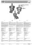
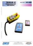
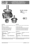
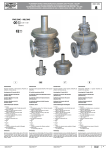
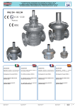
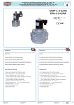
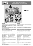
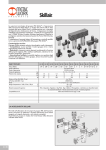
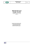
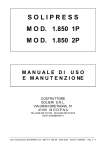
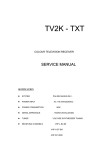
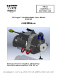
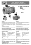
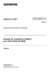
MADAS
FILTROREGOLATORI e REGOLATORI GAS A CHIUSURA TIPO
FRG/2MB MIN - RG/2MB MIN CON BLOCCO DI MINIMA PRESSIONE
®
FRG/2MB MIN - RG/2MB MIN GAS FILTER REGULATORS and GAS
REGULATORS WITH LOW PRESSURE OUTLET CLOSING
© 2004 MADAS s.r.l.
FRG/2MB MIN - RG/2MB MIN
II 2G - II 2D
MADAS-03
0497
DESCRIZIONE
DESCRIPTION
Il filtroregolatore serie FRG/2MB MIN o regolatore RG/2MB MIN è costiutito
dall'accoppiamento di un filtroregolatore FRG/2MC o regolatore RG/2MC ed una
valvola di blocco di minima pressione.
Si comporta quindi come un regolatore a chiusura ma quando la pressione di
regolazione va al di sotto, per cause accidentali, al valore della pressione di taratura
del blocco, si ha l'intervento automatico di quest'ultimo che, con una chiusura a
campana completamente indipendente dal regolatore, blocca a monte il flusso
del gas mettendo l'intero sistema in una situazione di sicurezza.
L'apertura della valvola di blocco può avvenire solo manualmente e solo dopo
che si è trovato ed eliminato l'inconveniente che ha provocato la chiusura.
The FRG/2MB MIN filter regulator or RG/2MB MIN regulator is made up of the
coupling of a FRG/2MC filter regulator or a RG/2MC regulator and a shut off
valve of low pressure.
It works as a closing regulator but when the value of the regulation pressure
goes down, for accidental causes, the shut set pressure, the latter automatically
intervenes and shuts upstream (with a bell closure completely independent from
the regulator) the gas flux for the plant safety.
Conforme Direttiva 90/396/CEE (Direttiva Gas)
In conformity with the 90/396/EEC Directive (Gas Directive)
Conforme Direttiva 97/23/CE (Direttiva PED)
In conformity with the 97/23/EC Directive (PED Directive)
Conforme Direttiva 94/9/CE (Direttiva ATEX)
In conformity with the 94/9/EC Directive (ATEX Directive)
CARATTERISTICHE TECNICHE
TECHNICAL DATA
- Impiego
- Temperatura ambiente
- Temperatura superficiale max
- Pressione max di esercizio
- Campo pressione intervento
- Tempo di chiusura blocco
- Filtraggio
- Classe di filtrazione
- Attacchi filettati
- Use
- Environment temperature
- Max. superficial temperature
- Max. working pressure
- Intervention pressure range
- Shut closing time
- Filtration
- Filtration class
- Threaded connections
: Gas non aggressivi delle 3 famiglie (gas secchi)
: -15 ÷ +60 °C
: 60 °C
: 1 bar
: 8 ÷ 22 mbar
:<1s
: 50 µm (su richiesta altre qualità di filtraggio)
: G 2 (secondo EN 779)
: (DN 15 ÷ DN 50) secondo ISO 7/1
The opening of the shut valve is only manual after verifying the causes that
provoked the shut.
: Not aggressive gases of the 3 families (dry gases)
: -15 ÷ +60 °C
: 60 °C
: 1 bar
: 8 ÷ 22 mbar
:<1s
: 50 µm (on request other filtration qualities)
: G 2 (acording to EN 779)
: (DN 20 ÷ DN 50) according to ISO 7/1
Materiali
Materials
Alluminio pressofuso (UNI EN 1706), alluminio 11S (UNI 9002-5),
ottone OT-58 (UNI EN 12164), acciaio INOX 430 F (UNI EN 10088), gomma
antiolio NBR (UNI 7702), viledon.
Die-cast aluminium (UNI EN 1706), 11S aluminium (UNI 9002-5), OT-58
brass (UNI EN 12164), 430 F stainless steel (UNI EN 10088), NBR rubber
(UNI 7702), viledon.
MADAS - Manuale Tecnico 2004
MADAS - 2004 Technical Manual
FRG/2MB MIN - RG/2MB MIN
Capitolo 23 (Rev. 0)
Chapter 23 (Rev. 0)
pag. 1
MADAS
®
© 2004 MADAS s.r.l.
FILTROREGOLATORI e REGOLATORI GAS A CHIUSURA TIPO
FRG/2MB MIN - RG/2MB MIN CON BLOCCO DI MINIMA PRESSIONE
FRG/2MB MIN - RG/2MB MIN GAS FILTER REGULATORS and GAS
REGULATORS WITH LOW PRESSURE OUTLET CLOSING
fig. 1
codice
filtroregolatore
codice
regolatore
attacchi
filter regulator
code
regulator
code
connections
FB030007
RB030007
DN 20
FB040007
RB040007
DN 25
FB050007
RB050007
DN 32
FB060007
RB060007
DN 40
FB070007
RB070007
DN 50
A
1 - Tappo in alluminio
2 - Vite di regolazione taratura (regolatore)
3 - Molla di taratura (regolatore)
4 - Tappo antipolvere
5 - Membrana di sicurezza (regolatore)
6 - Membrana di funzionamento (regolatore)
7 - Corpo regolatore
8 - Perno otturatore
9 - Raccordo di collegamento tubetto
10 - Otturatore a campana
11 - Otturatore
12 - Membrana di funzionamento (blocco)
13 - Membrana di sicurezza (blocco)
14 - Disco superiore per membrana (blocco)
15 - Disco inferiore per membrana (blocco)
16 - Tappo in plastica
17 - Imbuto (blocco)
18 - Vite di regolazione intervento blocco
19 - Molla di taratura (blocco)
MADAS - Manuale Tecnico 2004
MADAS - 2004 Technical Manual
20 - Viti di fissaggio imbuto (blocco)
21 - Dado M5
22 - Dado blocca membrana
23 - Raccordo di collegamento tubetto
24 - Manopola di riarmo e di protezione
25 - Perno di riarmo
26 - Rondella di tenuta
27 - O-Ring di tenuta otturatore blocco
28 - Viti di fissaggio fondello
29 - Fondello
30 - O-Ring di tenuta fondello
31 - Organo filtrante
32 - Presa di pressione
33 - Viti di fissaggio imbuto (regolatore)
34 - Disco superiore per membrana (regolatore)
35 - Disco inferiore per membrana (regolatore)
36 - Dado blocca membrana
37 - Imbuto (regolatore)
1 - Aluminium cap
2 - Regulation setting screw (regulator)
3 - Setting spring (regulator)
4 - Antidust cap
5 - Safety diaphragm (regulator)
6 - Working diaphragm (regulator)
7 - Body regulator
8 - Obturator pin
9 - Pipe-fitting connection tube
10 - Bell obturator
11 - Obturator
12 - Working diaphragm (shut)
13 - Safety diaphragm (shut)
14 - Diaphragm upper disc (shut)
15 - Diaphragm lower disc (shut)
16 - Plastic cap
17 - Funnel (shut)
18 - Shut intervention setting screw
19 - Setting spring (shut)
FRG/2MB MIN - RG/2MB MIN
20 - Funnel fixing screws (shut)
21 - M5 nut
22 - Blocking membrane nut
23 - Pipe-fitting connection tube
24 - Reset and protection handgrip
25 - Reset pin
26 - Seal washer
27 - Shut seal O-Ring
28 - Bottom fixing screws
29 - Bottom
30 - Bottom seal O-Ring
31 - Filtering organ
32 - Pressure tap
33 - Funnel fixing screws (regulator)
34 - Diaphragm upper disc (regulator)
35 - Diaphragm lower disc (regulator)
36 - Blocking membrane nut
37 - Funnel (regulator)
Capitolo 23 (Rev. 0)
Chapter 23 (Rev. 0)
pag. 2
MADAS
®
© 2004 MADAS s.r.l.
FILTROREGOLATORI e REGOLATORI GAS A CHIUSURA TIPO
FRG/2MB MIN - RG/2MB MIN CON BLOCCO DI MINIMA PRESSIONE
FRG/2MB MIN - RG/2MB MIN GAS FILTER REGULATORS and GAS
REGULATORS WITH LOW PRESSURE OUTLET CLOSING
Caratteristiche molle di regolazione / Regulation springs data
codice molla
spring code
connections
attacchi
taratura (mbar)
MO-0400
DN 20 - DN 25
9 ÷ 25
MO-0500
DN 20 - DN 25
15 ÷ 45
MO-0825
DN 20 - DN 25
30 ÷ 120
MO-0900
DN 20 - DN 25
100 ÷ 150
MO-1005
DN 20 - DN 25
140 ÷ 320
MO-1305*
DN 20 - DN 25
150 ÷ 450
MO-0825
DN 32 - DN 40
5 ÷ 23
MO-0900
DN 32 - DN 40
12 ÷ 35
MO-1000
DN 32 - DN 40
32 ÷ 100
MO-1300
DN 32 - DN 40
85 ÷ 200
MO-1300*
DN 32 - DN 40
85 ÷ 250
MO-2550*
DN 32 - DN 40
85 ÷ 500
MO-0825
DN 50
11 ÷ 25
MO-0900
DN 50
20 ÷ 45
MO-1000
DN 50
45 ÷ 100
MO-1300
DN 50
100 ÷ 180
MO-2550
DN 50
130 ÷ 200
MO-1300*
DN 50
200 ÷ 400
MO-2550*
DN 50
200 ÷ 500
setting (mbar)
* Da utilizzare su versioni con membrana telata
* To use only with reinforced diaphragm
Molle di taratura per il blocco di minima / Setting springs for minimum shut
codice molla
MADAS - Manuale Tecnico 2004
MADAS - 2004 Technical Manual
spring code
connections
attacchi
taratura (mbar)
MO-0200
DN 20 - DN 50
8 ÷ 22
setting (mbar)
FRG/2MB MIN - RG/2MB MIN
Capitolo 23 (Rev. 0)
Chapter 23 (Rev. 0)
pag. 3
MADAS
®
© 2004 MADAS s.r.l.
FILTROREGOLATORI e REGOLATORI GAS A CHIUSURA TIPO
FRG/2MB MIN - RG/2MB MIN CON BLOCCO DI MINIMA PRESSIONE
FRG/2MB MIN - RG/2MB MIN GAS FILTER REGULATORS and GAS
REGULATORS WITH LOW PRESSURE OUTLET CLOSING
Diagramma perdite di carico regolatori senza filtro (RG/2MB)
DN
3
DN 2
40
DN
50
25
DN
DN
20
Capacity diagram of regulators without filter (RG/2MB)
metano
methane
aria
air
gas di città
town gas
gpl
lpg
Diagramma perdite di carico regolatori con filtro (FRG/2MB)
50
DN
40
32
DN
DN
25
DN
DN
20
Capacity diagram of regulators with filter (FRG/2MB)
metano
methane
aria
air
gas di città
town gas
gpl
lpg
MADAS - Manuale Tecnico 2004
MADAS - 2004 Technical Manual
FRG/2MB MIN - RG/2MB MIN
Capitolo 23 (Rev. 0)
Chapter 23 (Rev. 0)
pag. 4
MADAS
FILTROREGOLATORI e REGOLATORI GAS A CHIUSURA TIPO
FRG/2MB MIN - RG/2MB MIN CON BLOCCO DI MINIMA PRESSIONE
®
FRG/2MB MIN - RG/2MB MIN GAS FILTER REGULATORS and GAS
REGULATORS WITH LOW PRESSURE OUTLET CLOSING
© 2004 MADAS s.r.l.
Misure di ingombro in mm
Overall dimensions in mm
codice
filtroregolatore
codice
regolatore
Superficie
filtrante (mm2)
attacchi
A
B
C
filter regulator
code
regulator
code
connections
Filtering
surface (mm2)
FB030007
RB030007
DN 20
120
311
344
8640
FB040007
RB040007
DN 25
120
311
344
8640
FB050007
RB050007
DN 32
160
368
401
16000
FB060007
RB060007
DN 40
160
368
401
16000
FB070007
RB070007
DN 50
160
390
424
23000
C = Spazio necessario per il riarmo
C = Space requirements for reset
INSTALLAZIONE
INSTALLATION
Il regolatore è conforme alla Direttiva 94/9/CE (denominata Direttiva ATEX 100
a) come apparecchio del gruppo II, categoria 2G e come apparecchio del gruppo
II, categoria 2D; come tale è idoneo per essere installato nelle zone 1 e 21 (oltre
che nelle zone 2 e 22) come classificate nell’allegato I alla Direttiva 99/92/CE.
Il regolatore non è idoneo per l’utilizzo nelle zone 0 e 20 come definite nella già
citata Direttiva 99/92/CE.
Per determinare la qualifica e l’estensione delle zone pericolose si veda la norma
EN 60079-10.
The regulator is in conformity with the Directive 94/9/CE (said Directive ATEX
100 a) as device of group II, category 2G and as device of group II, category
2D; for this reason it is suitable to be installed in the zones 1 and 21 (besides in
the zones 2 and 22) as classified in the attachment I to the Directive 99/92/EC.
The regulator is not suitable to be used in zones 0 and 20 as classified in the
already said Directive 99/92/EC.
To determine the qualification and the extension of the dangerous zones, see
the norm EN 60079-10.
L’apparecchio, se installato e sottoposto a manutenzione nel pieno rispetto di
tutte le condizioni e istruzioni tecniche riportate nel presente documento, non
costituisce fonte di pericoli specifici: in particolare, in condizioni di normale
funzionamento, è prevista, da parte del regolatore, l’emissione in atmosfera di
sostanza infiammabile solo occasionalmente.
The device, if installed and serviced respecting all the conditions and the technical instructions of this document, is not source of specific dangers: in particular,
during the normal working, is forecast, by the regulator, the emission in the
atmosphere of inflammable substance only occasionally.
Il regolatore può essere pericoloso rispetto alla presenza nelle sue vicinanze di
altre apparecchiature solo in caso di guasto sia della membrana di funzionamento
(6) che della membrana di sicurezza (5) del regolatore o in caso di guasto sia
della membrana di funzionamento (12) che della membrana di sicurezza (13) del
blocco: in questi due casi (e solo in questi) il regolatore costituisce una sorgente
di emissione di atmosfera esplosiva di grado continuo e, come tale, può originare
zone pericolose 0 come definite nella Direttiva 99/92/CE.
In condizioni di installazione particolarmente critica (luoghi non presidiati, carenza
di manutenzione, scarsa disponibilità di ventilazione) e, soprattutto in presenza
nelle vicinanze del regolatore di potenziali fonti di innesco e/o apparecchiature
pericolose nel funzionamento ordinario in quanto suscettibili di originare archi
elettrici o scintille, è necessario valutare preliminarmente la compatibilità fra il
regolatore e tali apparecchiature.
In ogni caso è necessario prendere ogni precauzione utile ad evitare che il regolatore sia origine di zone 0: ad esempio verifica periodica annuale di regolare
funzionamento, possibilità di modificare il grado di emissione della sorgente o di
intervenire sullo scarico all’esterno della sostanza esplosiva.
A tal fine è possibile collegare all’esterno tramite un tubo di rame i fori filettati
G ¼” togliendo i rispettivi tappi antipolvere (4) in ottone.
The regulator can be dangerous as regards to the presence close to it of other
devices only in case of damage either of the working diaphragm (6) or of the
safety one (5) or in case of damage either of the shut working diaphragm (12)
or of the safety one (13): only in these two cases the regulator is a source of
emission of the continue degree explosive atmosphere and, so, it can originate
dangerous areas 0 as defined in the 99/92/EC Directive.
Il regolatore è normalmente posizionato prima dell’utenza. Deve essere installato
con la freccia (in rilievo sul corpo (7)) rivolta verso l’utenza e con la molla (3) in
posizione verticale (vedi fig. 1).
The regulator is normally installed before the user. It must be installed with the
arrow (on the body (7)) towards the user and with the spring (3) in vertical
position (see fig. 1).
Si raccomanda di leggere attentamente il foglio di
istruzioni a corredo di ogni prodotto.
MADAS - Manuale Tecnico 2004
MADAS - 2004 Technical Manual
In conditions of particularly critic installation (places not protected, lack of
servicing, lacking availability of ventilation) and, especially in presence, close to
the regulator, of potential sources of primer and/or dangerous devices during
the normal working because susceptible to origine electric arcs or sparks, it is
necessary to value before the compatibility between the regulator and these
devices.
In any case it is necessary to take any useful precaution to avoid that the
regulator could be origin of areas 0: for example yearly periodical inspection of
regular working, possibility to change the emission degree of the source or to
attend on the exhaust outside the explosive material.
To do so it is possible to connect outside by a copper pipe the threaded holes G
¼” removing the rispective brass anti-dust caps (4).
It is always important to read carefully the instruction
sheet of each product.
FRG/2MB MIN - RG/2MB MIN
Capitolo 23 (Rev. 0)
Chapter 23 (Rev. 0)
pag. 5
MADAS
®
© 2004 MADAS s.r.l.
FILTROREGOLATORI e REGOLATORI GAS A CHIUSURA TIPO
FRG/2MB MIN - RG/2MB MIN CON BLOCCO DI MINIMA PRESSIONE
FRG/2MB MIN - RG/2MB MIN GAS FILTER REGULATORS and GAS
REGULATORS WITH LOW PRESSURE OUTLET CLOSING
ESEMPIO DI INSTALLAZIONE
EXAMPLE OF INSTALLATION
1. Valvola a strappo SM
2. Filtroregolatore gas tipo FRG/2MB MIN
3. Valvola di sfioro MVS/1
4. Leva comando a distanza valvola a strappo SM
1. SM series jerk handle ON/OFF valve
2. FRG/2MB MIN series filter pressure regulator
3. MVS/1 series overflow valves
4. Lever for remote SM ON/OFF valve control
Scarico in
aria libera
Free air
exhaust
rete
utenza
pipe
user
RIARMO MANUALE
MANUAL RESET
Aprire lentamente la valvola di intercettazione a monte, svitare la manopola di
riarmo e di protezione (24), rovesciarla e avvitare il foro filettato “A” (vedi fig.
1) al perno di riarmo (25). A questo punto tirare verso il basso la manopola di
riarmo (24) fino ad avvenuto aggancio. Successivamente riavvitare la manopola
(24) nella posizione iniziale.
Slowly open the solenoid valve upstream, unscrew the reset and protection
handgrip (24), reverse it and screw the threaded hole “A” (see fig. 1) to reset
pin (25). Then, pull down the reset handgrip (24) up to the hooking. Afterwards
rescrew the reset handgrip (24) in the starting position.
TARATURA
CALIBRATION
- Aprire lentamente la valvola di intercettazione a monte
- Slowly open the solenoid valve upstream
- Se l’apparecchio non è già tarato procedere nel seguente modo:
- If the device is not set yet proceed as follows:
- Accertarsi che gli utilizzatori siano fermi
- Make sure that the users are not working
- Diminuire il valore della pressione di blocco svitando al minimo la vite di
regolazione blocco (18)
- Decrease the shut pressure value by screwing at minimum the shut setting
screw (18)
- Verificare tirando verso il basso la manopola (24) che il dispositivo di blocco
sia aperto.
- Pull down the handle (24) to make sure that the shut device is open
- Abbassare (svitando la vite (2)) la pressione di utilizzazione del regolatore
(pressione in uscita P2), fino ad ottenere la pressione di blocco desiderata
controllandola con un manometro
- Decrease (unscrewing the screw (2)) the user’s pressure regulator (outlet
pressure P2), to obtain the wanted regulation pressure (checking it by a
manometer)
- Avvitare lentamente la vite di regolazione del blocco (18) fino all’intervento
del dispositivo stesso
- Slowly screw the shut setting screw (18) up to the device intervention
- Ripristinare la pressione di esercizio del regolatore avvitando la vite di
regolazione del regolatore (2), e riarmare il dispositivo di blocco.
Successivamente richiudere i tappi (1) e (16).
- Restore the regulator working pressure screwing the regulation screw of the
regulator (2) and reset the shut device.
Then close the caps (1) and (16).
Le suddette operazioni devono essere eseguite
esclusivamente da tecnici qualificati.
MADAS - Manuale Tecnico 2004
MADAS - 2004 Technical Manual
The above-said operations must be carried out only
by qualified technicians.
FRG/2MB MIN - RG/2MB MIN
Capitolo 23 (Rev. 0)
Chapter 23 (Rev. 0)
pag. 6
MADAS
®
FILTROREGOLATORI e REGOLATORI GAS A CHIUSURA TIPO
FRG/2MB MIN - RG/2MB MIN CON BLOCCO DI MINIMA PRESSIONE
FRG/2MB MIN - RG/2MB MIN GAS FILTER REGULATORS and GAS
REGULATORS WITH LOW PRESSURE OUTLET CLOSING
© 2004 MADAS s.r.l.
MANUTENZIONE
SERVICING
Prima di effettuare qualsiasi operazione di smontaggio sull’apparecchio, assicurarsi
che all’interno dello stesso non ci sia gas in pressione.
Before disassembling the device make sure that there is no pressured gas
inside.
- Per controllare o sostituire le membrane, togliere l’imbuto (37) svitando le viti
di fissaggio (33), togliere la prima membrana (5), svitare il dado centrale (36)
che fissa la seconda membrana (6) (tra due dischi) al perno otturatore (8).
Per rimontare il tutto, eseguire il procedimento inverso facendo attenzione nello
stringere il dado (36) a non far ruotare le membrane (tenere fermo con la mano
libera il disco (34) posto sopra alla membrana (6)).
- To check or substitue the diaphragms, unscrew the fixing screws (33) and
remove the funnel (37), take off the first diaphragm (5), unscrew the central
nut (36) that fixes the second diaphragm (6) (between two discs) to the
obturator pin (8).
Reassemble doing backward the same operation, paying attention when tightenig
the nut (15) not to turn the membranes (hold with your free hand the disc (14)
on the membrane (5)).
- Eseguire lo stesso procedimento per sostituire le membrane del blocco.
- Execute the same operations to substitute the shut diaphragms
- Per controllare l’otturatore di chiusura (11) e l’organo filtrante (31), svitare il
raccordo (23) (per attacchi DN 20 - DN 25), svitare il raccordo (9) (per attacchi
DN 32 - DN 40 - DN 50). Successivamente togliere il coperchio inferiore (29)
dell’apparecchio (dispositivo di blocco), svitando le viti di fissaggio (28). Controllare l’otturatore (11) verificandone eventuali anomalie e se necessario sostituire
l’organo di tenuta in gomma (26).
Smontare l’organo filtrante (31), pulirlo con acqua e sapone, soffiarlo con aria
compressa o sostituirlo se necessario. Rimontarlo nella posizione iniziale controllando che sia sistemato tra le apposite guide (38) (vedi fig. 2).
Quindi procedere al montaggio facendo a ritroso l’operazione di smontaggio.
- To check the obturator (11) and the filtering component (31), unscrew the
pipe-fitting (23) (for DN 20 - DN 25 connections),unscrew the pipe-fitting (9)
(for DN 32 - DN 40 - DN 50 connections). Then unscrew the fixing screws (28),
remove the bottom cover (29) of the device (shut component) and check the
obturator (11) is in good working conditions and if necessary change the rubber
seal component (26).
Remove the filtering component (31) clean it with water and soap, blow it
with compressed air or substitute it if necessary. Reassemble it in its original
position, checking it is set in its special guides (38) (see fig. 2).
Then reassemble doing backward the same operation.
The above-said operations must be carried out only
by qualified technicians.
Le suddette operazioni devono essere eseguite
esclusivamente da tecnici qualificati.
fig. 2
38
31
VISTA: CORPO REGOLATORE
SENZA FONDELLO
VIEW: BODY REGULATOR WITHOUT
BOTTOM COVER
PER INSERIRE L'ORGANO
FILTRANTE:
TO INSERT THE FILTERING
Posizionarlo come in figura facendo
attenzione ad inserirlo all'interno
delle guide (38)
MADAS - Manuale Tecnico 2004
MADAS - 2004 Technical Manual
COMPONENT:
Position it as in the figure taking care to
put it inside the guides (38)
FRG/2MB MIN - RG/2MB MIN
Capitolo 23 (Rev. 0)
Chapter 23 (Rev. 0)
pag. 7
MADAS
®
FILTROREGOLATORI e REGOLATORI GAS A CHIUSURA TIPO
FRG/2MB MIN - RG/2MB MIN CON BLOCCO DI MINIMA PRESSIONE
FRG/2MB MIN - RG/2MB MIN GAS FILTER REGULATORS and GAS
REGULATORS WITH LOW PRESSURE OUTLET CLOSING
© 2004 MADAS s.r.l.
VERSIONI CON ATTACCHI (DN 25 - DN 32 - DN 40 - DN 50) FLANGIATI
VERSIONS WITH (DN 25 - DN 32 - DN 40 - DN 50) FLANGED CONNECTIONS
Misure di ingombro in mm
Overall dimensions in mm
Attacchi
A
B
C
DN 25
191
311
344
DN 32
280
368
401
DN 40
280
368
401
DN 50
280
390
424
Connections
C = Spazio necessario per il riarmo
C = Space requirements for reset
MADAS - Manuale Tecnico 2004
MADAS - 2004 Technical Manual
FRG/2MB MIN - RG/2MB MIN
Capitolo 23 (Rev. 0)
Chapter 23 (Rev. 0)
pag. 8