1
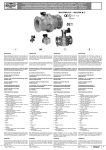
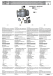
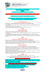
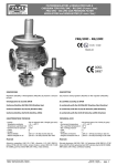
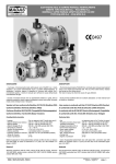
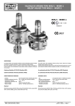
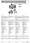
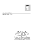
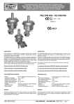
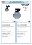
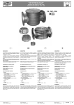
MADAS
ELETTROVALVOLE A RIARMO MANUALE NORMALMENTE
CHIUSE TIPO M16/RM N.C. - M16/RMO N.C.
®
NORMALLY-CLOSED MANUAL RESET SOLENOID VALVES
TYPE M16/RM N.C. - M16/RMO N.C.
© 2004 MADAS s.r.l.
M16/RM N.C. - M16/RMO N.C.
II 3G - II 3D
MADAS-04
0051
0497
DESCRIZIONE
DESCRIPTION
Questa elettrovalvola è costruita in modo tale da poter garantire l'intercettazione
del gas sia per segnalazioni di pericolo inviate da rivelatori presenza gas (metano,
gpl, ossido di carbonio e altri) o termostati di sicurezza, che per la mancanza di
tensione in rete (black out).
This solenoid valve is made to guarantee the gas interception either for gas
detector signals (methane, lpg, carbon monoxide and so on) and safety thermostats, or for an electric black out.
Per una maggior sicurezza questa elettrovalvola può essere riarmata solo in
presenza di tensione in rete e solo quando il rivelatore gas non dia segnalazioni
di pericolo.
In order to be more reliable this solenoid valve can be reset only when electrically
supplied and only if the gas detector doesn’t send any danger signal.
Omologazione CE secondo EN 161
EC certified according to EN 161
Conforme Direttiva 90/396/CEE (Direttiva Gas)
In conformity with the 90/396/EEC Directive (Gas Directive)
Versioni a 6 bar conformi alla Direttiva 97/23/CE (Direttiva PED)
6 bar versions in conformity with the 97/23/EC Directive (PED Directive)
Conforme Direttiva 94/9/CE (Direttiva ATEX)
In conformity with the 94/9/EC Directive (ATEX Directive)
Conforme Direttiva 89/336/CEE (Compatibilità Elettromagnetica)
In conformity with the 89/336/EEC Directive (Electromagnetic Compatibility)
Conforme Direttiva 73/23/CEE (Bassa Tensione)
In conformity with the 73/23/EEC Directive (Low Voltage)
CARATTERISTICHE TECNICHE
TECHNICAL DATA
-
- Use
- Threaded connections (brass body)
- Threaded connections
- Flanged connections PN 16
- Power supply voltage
- Power absorption
- Max. working pressure
- Environment temperature
- Max superficial temperature
- Protection degree
- Class
- Group
- Closing time
Impiego
Attacchi filettati (corpi ottone)
Attacchi filettati
Attacchi flangiati PN 16
Tensione di alimentazione
Potenza assorbita
Pressione max esercizio
Temperatura ambiente
Temperatura superficiale max
Grado di protezione
Classe
Gruppo
Tempo di chiusura
: Gas non aggressivi delle 3 famiglie (gas secchi)
: (DN 15 ÷ DN 25) secondo ISO 228/1
: (DN 20 ÷ DN 50) secondo ISO 7/1
: (DN 65 ÷ DN 200) secondo ISO 7005
: 12 V, 24 V, 110 V, 230 V
: vedi tabella
: 500 mbar o 6 bar (vedi etichetta prodotto)
: -15 ÷ +60 °C
: 80 °C
: IP65
:A
:2
: <1 s
: not aggressive gases of the 3 families (dry gases)
: (DN 15 ÷ DN 25) according to ISO 228/1
: (DN 20 ÷ DN 50) according to ISO 7/1
: (DN 65 ÷ DN 200) according to ISO 7005
: 12 V, 24 V, 110 V, 230 V
: see table
: 500 mbar or 6 bar (see product label)
: -15 ÷ +60 °C
: 80 °C
: IP65
:A
:2
: <1 s
- Bobine: incapsulate in resina poliammidica caricata con fibre di vetro con
attacco tipo DIN 43650; la classe di isolamento è la F (155°) ed il filo smaltato
è in classe H (180°)
Coils: poliammidic resin encapsulated with glass fibre, connection type DIN
43650; the insulation class is F (155°) and the enamelled copper wire class is
H (180°)
Materiali
Materials
Alluminio pressofuso (UNI EN 1706), ottone OT-58 (UNI EN 12164), alluminio
11S (UNI 9002-5), acciaio zincato e acciaio INOX 430 F (UNI EN 10088), gomma
antiolio NBR (UNI 7702), ovatta sintetica
Die-cast aluminium (UNI EN 1706), OT-58 brass (UNI EN 12164), 11S aluminium
(UNI 9002-5), galvanized and 430 F stainless steel (UNI EN 10088), NBR rubber
(UNI 7702), synthetical wadding
MADAS - Manuale Tecnico 2004 - Edizione 1
MADAS - 2004 Technical Manual - Ediction 1
M16/RM N.C. - M16/RMO N.C.
Capitolo 5 / Chapter 5
pag. 1
MADAS
®
© 2004 MADAS s.r.l.
ELETTROVALVOLE A RIARMO MANUALE NORMALMENTE
CHIUSE TIPO M16/RM N.C. - M16/RMO N.C.
NORMALLY-CLOSED MANUAL RESET SOLENOID VALVES
TYPE M16/RM N.C. - M16/RMO N.C.
fig. 1
1
2
3
4
5
6
7
8
9
10
11
- Connettore elettrico
- Coperchio
- Otturatore
- Dado autobloccante
- Corpo valvola
- Perno di riarmo
- Manopola copri-riarmo
- Molla di chiusura
- Viti di fissaggio coperchio
- Nucleo mobile
- Bobina elettrica
P. max 500 mbar
P. max 6 bar
attacchi
connections
codice / code
codice / code
CO02C
CO02C0000
DN 15*
CO03C
CO03C0000
DN 20*
CO04C
CO04C0000
DN 25*
CM03C
CM03C0000
DN 20
CM04C
CM04C0000
DN 25
CM05C
CM05C0000
DN 32
CM06C
CM06C0000
DN 40
CM07C
CM07C0000
DN 50
1 2 3 4 5 6 7 8 9 10 11 -
Electrical connector
Cover
Obturator
Self-blocking nut
Body of the valve
Reset pin
Cover for reset pin
Closing spring
Fixing cover screws
Movable plunger
Electrical coil
* = corpo in ottone = brass body
= M16/RMO N.C.
MADAS - Manuale Tecnico 2004 - Edizione 1
MADAS - 2004 Technical Manual - Ediction 1
M16/RM N.C. - M16/RMO N.C.
Capitolo 5 / Chapter 5
pag. 2
MADAS
®
© 2004 MADAS s.r.l.
ELETTROVALVOLE A RIARMO MANUALE NORMALMENTE
CHIUSE TIPO M16/RM N.C. - M16/RMO N.C.
NORMALLY-CLOSED MANUAL RESET SOLENOID VALVES
TYPE M16/RM N.C. - M16/RMO N.C.
fig. 2
A
1
2
3
4
5
6
7
8
9
10
11
12
13
14
15
16
17
- Perno di riarmo
- Connettore elettrico
- Molla di chiusura
- Viti di fissaggio coperchio
- Viti di fissaggio sede superiore
- Sede superiore
- Perno centrale
- Corpo valvola
- Fondello
- Otturatore inferiore
- Tubetto distanziale lungo
- Organo filtrante
- Otturatore superiore
- Coperchio
- Tubetto distanziale corto
- Bobina elettrica
- Manopola di riarmo
MADAS - Manuale Tecnico 2004 - Edizione 1
MADAS - 2004 Technical Manual - Ediction 1
P. max 500 mbar
P. max 6 bar
attacchi
connections
codice / code
codice / code
CX08C
CX08C0000
DN 65
CX09C
CX09C0000
DN 80
CX10C
CX10C0000
DN 100
1 2 3 4 5 6 7 8 9 10 11 12 13 14 15 16 17 -
Reset pin
Electrical connector
Closing spring
Fixing cover screws
Fixing upper seat
Upper seat
Central pin
Body of the valve
Bottom
Lower obturator
Long spacer
Filtering component
Upper obturator
Cover
Short spacer
Electrical coil
Reset handle
M16/RM N.C. - M16/RMO N.C.
Capitolo 5 / Chapter 5
pag. 3
MADAS
ELETTROVALVOLE A RIARMO MANUALE NORMALMENTE
CHIUSE TIPO M16/RM N.C. - M16/RMO N.C.
®
NORMALLY-CLOSED MANUAL RESET SOLENOID VALVES
TYPE M16/RM N.C. - M16/RMO N.C.
© 2004 MADAS s.r.l.
fig. 3
P. max 500 mbar
1
2
3
4
-
P. max 6 bar
attacchi
connections
codice / code
codice / code
CX11C
CX11C0000
DN 125
CX12C
CX12C0000
DN 150
Connettore
Bobina elettrica
Manopola di riarmo
Corpo in alluminio
1
2
3
4
- Electrical connector
- Electrical coil
- Reset handle
- Aluminium body
fig. 4
P. max 500 mbar
P. max 6 bar
codice / code
codice / code
CX13C
CX13C0000
MADAS - Manuale Tecnico 2004 - Edizione 1
MADAS - 2004 Technical Manual - Ediction 1
attacchi
connections
DN 200
M16/RM N.C. - M16/RMO N.C.
Capitolo 5 / Chapter 5
pag. 4
NORMALLY-CLOSED MANUAL RESET SOLENOID VALVES
TYPE M16/RM N.C. - M16/RMO N.C.
*-
0
DN
Diagramma perdite di carico / Capacity diagram
DN
512
0
10
DN
20
0
DN
DN
6
DN 5
80
50
40
DN
32
DN
DN
DN
-D
N
20
DN
20
DN
DN
15
*
*
25
15
© 2004 MADAS s.r.l.
25
MADAS
ELETTROVALVOLE A RIARMO MANUALE NORMALMENTE
CHIUSE TIPO M16/RM N.C. - M16/RMO N.C.
®
1
2
3
4
1) metano - methane
2) aria - air
3) gas di città - town gas
4) gpl - lpg
* = corpi in ottone M16/RMO N.C. = brass body M16/RMO N.C.
Dimensioni di ingombro in mm
Overall dimensions in mm
P. max 500 mbar
P. max 6 bar
codice / code
codice / code
connections
CO02C
CO02C0000
CO03C
attacchi
A
B
DN 15*
55
130
CO03C0000
DN 20*
55
130
CO04C
CO04C0000
DN 25*
82
142
CM03C
CM03C0000
DN 20
120
173
CM04C
CM04C0000
DN 25
120
173
CM05C
CM05C0000
DN 32
160
237
CM06C
CM06C0000
DN 40
160
237
CM07C
CM07C0000
DN 50
160
266
CX08C
CX08C0000
DN 65
310
375
CX09C
CX09C0000
DN 80
310
375
CX10C
CX10C0000
DN 100
310
415
CX11C
CX11C0000
DN 125
490
460
CX12C
CX12C0000
DN 150
490
470
CX13C
CX13C0000
DN 200
600
490
* = corpi in ottone M16/RMO N.C. = brass body M16/RMO N.C.
MADAS - Manuale Tecnico 2004 - Edizione 1
MADAS - 2004 Technical Manual - Ediction 1
M16/RM N.C. - M16/RMO N.C.
Capitolo 5 / Chapter 5
pag. 5
MADAS
®
© 2004 MADAS s.r.l.
ELETTROVALVOLE A RIARMO MANUALE NORMALMENTE
CHIUSE TIPO M16/RM N.C. - M16/RMO N.C.
NORMALLY-CLOSED MANUAL RESET SOLENOID VALVES
TYPE M16/RM N.C. - M16/RMO N.C.
INSTALLAZIONE
INSTALLATION
L’elettrovalvola è conforme alla Direttiva 94/9/CE (denominata Direttiva ATEX
100 a) come apparecchio del gruppo II, categoria 3G e come apparecchio II,
categoria 3D; come tale è idonea per essere installata nelle zone 2 e 22 come
classificate nell’allegato I alla Direttiva 99/92/CE.
L’elettrovalvola non è idonea per l’utilizzo nelle zone 1 e 21 e, a maggior ragione,
nelle zone 0 e 20 come definite nella già citata Direttiva 99/92/CE.
Per determinare la qualifica e l’estensione delle zone pericolose si veda la norma
EN 60079-10.
The solenoid valve is in conformity with the Directive 94/9/CE (said Directive
ATEX 100 a) as device of group II, category 3G and as device of group II, category 3D; for this reason it is suitable to be installed in the zones 2 and 22 as
classified in the attachment I to the Directive 99/92/EC.
The solenoid valve is not suitable to be used in zones 1 and 21 and, all the more
so, in zones 0 and 20 as classified in the already said Directive 99/92/EC.
To determine the qualification and the extension of the dangerous zones, see
the norm EN 60079-10.
L’apparecchio, se installato e sottoposto a manutenzione nel pieno rispetto di
tutte le condizioni e istruzioni tecniche riportate nel presente documento, non
costituisce fonte di pericoli specifici: in particolare, in condizioni di normale funzionamento, non è prevista, da parte dell’elettrovalvola, l’emissione in atmosfera
di sostanza infiammabile con modalità tali da originare un’atmosfera esplosiva.
The device, if installed and serviced respecting all the conditions and the technical instructions of this document, is not source of specific dangers: in particular,
during the normal working, is not forecast, by the solenoid valve, the emission
in the atmosphere of inflammable substance in way to cause an explosive atmosphere.
Normalmente vengono installate a monte degli organi di regolazione e devono
essere installate con la freccia (indicata sul corpo delle elettrovalvole) rivolta
verso l’utenza. Possono essere installate anche in posizione verticale senza che
ne venga pregiudicato il corretto funzionamento. Non possono essere posizionate
capovolte.
It is usually installed upstream the regulation organs and it must be installed
with the arrow (shown on the valve body) towards the user.
They can be installed in vertical position without compromising the correct
working. It must not be installed overturned.
Si raccomanda di leggere attentamente il foglio di
istruzioni a corredo di ogni prodotto.
It is always important to read carefully the instruction
sheet of each product.
ESEMPIO DI INSTALLAZIONE
EXAMPLE OF INSTALLATION
1. Elettrovalvola a riarmo manuale M16/RM N.C.
2. Valvola a strappo SM
3. Filtroregolatore FRG/2MC
4. Manometro
5. Rivelatore gas
6. Leva comando a distanza valvola a strappo SM
1. M16/RM N.C. manual reset solenoid valve
2. SM series jerk handle ON/OFF valve
3. FRG/2MC series filter pressure regulator
4. Manometer
5. Gas detector
6. Lever for remote SM ON/OFF valve control
utenza
rete
user
pipe
RIARMO MANUALE
MANUAL RESET
Per riarmare l'elettrovalvola, assicurarsi di essere in presenza di tensione e svitare
completamente l'eventuale coperchietto di protezione.
To reset the solenoid valve, pay attention there is tension and unscrew completely
the possible protective small cap.
- con attacchi DN 15 ÷ DN 50: (vedi fig. 1) premere a fondo il perno di riarmo
(6) e attendere qualche istante che si verifichi l'equilibrio di pressione tra monte
e valle della valvola fino ad avvenuto aggancio*
- with connections DN 15 ÷ DN 50: (see fig. 1) push the reset handgrip (6)
and wait for an istant the balance between the inlet and outlet pressure of the
valve up to the hooking *
- con attacchi DN 65 ÷ DN 100: (vedi fig. 2) avvitare la manopola di riarmo
(17) tramite il foro filettato "A" sul perno di riarmo (1) e tirare la manopola (17)
verso l'alto fino ad avvenuto aggancio *
- with connections DN 65 ÷ DN 100: (see fig. 2) screw the reset handgrip
by the threaded hole “ A “ on the reset pin (1) and pull up the reset handgrip
(17) up to the hooking *
- con attacchi DN 125 ÷ DN 200: (vedi fig. 3 e 4) ruotare leggermente in
senso orario, con una chiave commerciale da 32 mm, la manopola di riarmo (3)
e attendere qualche istante che si verifichi l'equilibrio di pressione tra monte e
valle della valvola. Successivamente ruotare fino a fine corsa, sempre in senso
orario, la manopola di riarmo (3) fino ad avvenuto aggancio *
- with connections DN 125 ÷ DN 200: (see fig. 3 and 4) by a 32 mm commercial key turn slightly clockwise the reset handgrip (3) and wait for an istant
the balance between the inlet and outlet pressure of the valve. Then turn to the
end clockwise the reset handgrip (3) up to the hooking *
* riavvitare nella posizione originale il coperchietto di protezione ed eventualmente sigillarlo in quella posizione.
* rescrew in the original position the protective small cap and possibly seal it
in that position.
MADAS - Manuale Tecnico 2004 - Edizione 1
MADAS - 2004 Technical Manual - Ediction 1
M16/RM N.C. - M16/RMO N.C.
Capitolo 5 / Chapter 5
pag. 6
MADAS
ELETTROVALVOLE A RIARMO MANUALE NORMALMENTE
CHIUSE TIPO M16/RM N.C. - M16/RMO N.C.
®
NORMALLY-CLOSED MANUAL RESET SOLENOID VALVES
TYPE M16/RM N.C. - M16/RMO N.C.
© 2004 MADAS s.r.l.
MANUTENZIONE
SERVICING
In caso di necessità prima di effettuare verifiche interne accertarsi che :
If it is necessary, before doing the internal inspection, make sure that:
- l'elettrovalvola non sia alimentata elettricamente
- all'interno della stessa non vi sia gas in pressione
- the solenoid valve is not electrically supplied
- there is not gas inside the solenoid valve
- con attacchi DN 15 ÷ DN 50 e DN 125 - DN 150: (vedi fig. 1) con un
cacciavite svitare le viti di fissaggio (9) e con molta attenzione sfilare il coperchio
(2) dal corpo valvola (5), quindi controllare l'otturatore e se necessario sostituire
l'organo di tenuta in gomma (3). Successivamente pulire o soffiare il filtro (12) o
se necessario sostituirlo (per il posizionamento vedi fig. 5 e 6); quindi procedere
al montaggio facendo a ritroso l'operazione di smontaggio.
- with connections DN 15 ÷ DN 50 and DN 125 - DN 150: (see fig. 1)
unscrew by a screwdriver the fixing screws (9) and, with care, take the cover
(2) off the body (5) of the valve, then control the obturator and if it is necessary change the rubber made seal component (3). Then clean or blow the filter
(12) or change it if necessary (for the correct position see fig. 5 and 6); then
assemble doing backward the same operation.
- con attacchi DN 65 ÷ DN 100: (vedi fig. 2) svitare con un cacciavite le viti di
fissaggio (4) del coperchio (14) e con molta attenzione sfilarlo dal corpo valvola
(8), succesivamente per controllare gli otturatori procedere nel seguente modo:
svitare le viti di fissaggio (5) per la sede superiore (6) e sfilarla dal corpo valvola
(8). Se necessario pulirla accuratamente assieme all'O-Ring ad essa accoppiato.
Rimuovere il pacchetto otturatori-perno e pulire o sostituire se necessario gli organi
di tenuta in gomma. Controllare successivamente l'organo filtrante (12), soffiarlo,
pulirlo con acqua e sapone o se necessario sostituirlo. In ogni caso assicurarsi
di rimontarlo all'interno delle apposite guide (18) (vedi fig. 5). Poi procedere al
montaggio facendo a ritroso l'operazione di smontaggio.
- with connections DN 65 ÷ DN 100: (see fig. 2) unscrew by a screwdriver
the fixing screws (4) of the cover (14) and, with care, take it out of the body
of the valve (8), then control the obturators by proceding in this way: unscrew
the upper seat (6) fixing screws (5) and take it off the body (8) of the valve. If
it is necessary clean it with its O-Ring.
Remove the system obturators-pin and clean or, if it is necessary, change the
rubber made seal components.
Then control the filtering component (12), blow it, clean it with water and soap
or, if it is necessary, change it.
In any case pay attention to assemble inside the special guide (18) (see fig. 5).
Then assemble doing backward the same operation.
- con attacchi DN 200: non è previsto alcun tipo di manutenzione.
- with connections DN 200: it is not necessary any type of servicing.
The above-said operations must be carried out only
by qualified technicians.
Le suddette operazioni devono essere eseguite
esclusivamente da tecnici qualificati.
VISTA: CORPO VALVOLA SENZA COPERCHIO
VIEW: BODY OF THE VALVE WITHOUT COVER
PER INSERIRE LA RETE:
TO INSERT THE NET:
Posizionarla come in figura facendo attenzione a rispettare le guide sulla circonferenza interna del corpo valvola e bloccarla con le tre viti apposite (M3x10)
Position it as in the figure taking care to respect the guides in the internal circumference of the body valve and fix it by the three special screws (M3x10)
PER INSERIRE L'ORGANO FILTRANTE:
TO INSERT THE FILTERING ORGAN:
Posizionarlo come in figura facendo attenzione ad inserirlo all'interno delle
guide (18)
Position it as in the figure taking care to put it inside the guides (18)
fig. 5
18
12
12
MADAS - Manuale Tecnico 2004 - Edizione 1
MADAS - 2004 Technical Manual - Ediction 1
M16/RM N.C. - M16/RMO N.C.
Capitolo 5 / Chapter 5
pag. 7
MADAS
ELETTROVALVOLE A RIARMO MANUALE NORMALMENTE
CHIUSE TIPO M16/RM N.C. - M16/RMO N.C.
®
NORMALLY-CLOSED MANUAL RESET SOLENOID VALVES
TYPE M16/RM N.C. - M16/RMO N.C.
© 2004 MADAS s.r.l.
PER INSERIRE L'ORGANO FILTRANTE IN DN 125 - DN 150:
TO INSERT THE FILTERING ORGAN IN DN 125 - DN 150:
Posizionarlo come in figura, in modo che le apposite alette (19) risultino appoggiate al corpo. Infine rimontare il coperchio facendo attenzione che l'O-Ring sia
sistemato nell'apposita cava
Put it as in figure, so that the special fins (19) are leant against the body. So
reassemble the cover paying attention that the O-Ring is into the right hole
19
fig. 6
12
19
VERSIONI CON ATTACCHI (DN 25 - DN 32 - DN 40 - DN 50) FLANGIATI
VERSIONS (DN 25 - DN 32 - DN 40 - DN 50) WITH FLANGED CONNECTIONS
Misure di ingombro in mm
Overall dimensions in mm
Attacchi
A
B
DN 25
160
180
DN 32
200
237
DN 40
200
237
DN 50
216
266
Connections
MADAS - Manuale Tecnico 2004 - Edizione 1
MADAS - 2004 Technical Manual - Ediction 1
M16/RM N.C. - M16/RMO N.C.
Capitolo 5 / Chapter 5
pag. 8
MADAS
ELETTROVALVOLE A RIARMO MANUALE NORMALMENTE
CHIUSE TIPO M16/RM N.C. - M16/RMO N.C.
®
NORMALLY-CLOSED MANUAL RESET SOLENOID VALVES
TYPE M16/RM N.C. - M16/RMO N.C.
© 2004 MADAS s.r.l.
Bobine e connettori per elettrovalvole M16/RM N.C. - M16/RMO N.C.
Coils and connectors for M16/RM N.C. - M16/RMO N.C. solenoid valve
Attacchi
Connections
Tensione di
alimentazione
Codice
bobina
Timbratura
bobina
Codice
connettore
12 Vdc
BO-0030
12 V DC R
CN-0010
12 Vac
BO-0030
12 V DC R
CN-0050
24 Vdc
BO-0040
24 V DC R
CN-0010
M16/RM N.C.
DN 65 ÷ DN 200
M16/RM N.C.
DN 20 ÷ DN 50
M16/RMO N.C.
DN 15 ÷ DN 25
(corpi in ottone / brass body)
Power supply
voltage
Coil
code
Coil
stamping
Connector
code
24 Vac
BO-0040
24 V DC R
CN-0050
110 Vac
BO-0075
110 V RAC
CN-0045
230 Vac
BO-0050
220 V RAC
CN-0045
12 Vdc
BO-0030
12 V DC R
CN-0010
12 Vac
BO-0030
12 V DC R
CN-0050
24 Vdc
BO-0040
24 V DC R
CN-0010
24 Vac
BO-0040
24 V DC R
CN-0050
110 Vac
BO-0075
110 V RAC
CN-0045
230 Vac
BO-0050
220 V RAC
CN-0045
12 Vdc
BO-0275
V 12 DC W18
CN-0010
12 Vac
BO-0275
V 12 DC W18
CN-0050
24 Vdc
BO-0285
V 24 DC W18
CN-0010
24 Vac
BO-0285
V 24 DC W18
CN-0050
110 Vac
BO-0315
V 98 DC W18
CN-0045
230 Vac
BO-0325
V 196 DC W 18
CN-0045
Tipo
connettore
Potenza
assorbita
Connector
type
Power
absorption
NORMALE
NORMAL
RADDRIZZATORE
per 12 Vac e 24 Vac
RECTIFIER for
12 Vac and 24 Vac
NORMALE
NORMAL
RADDRIZZATORE
per 12 Vac e 24 Vac
RECTIFIER for
12 Vac and 24 Vac
RADDRIZZATORE
RECTIFIER
RADDRIZZATORE
RECTIFIER
NORMALE
NORMAL
RADDRIZZATORE
per 12 Vac e 24 Vac
RECTIFIER for
12 Vac and 24 Vac
NORMALE
NORMAL
RADDRIZZATORE
per 12 Vac e 24 Vac
RECTIFIER for
12 Vac and 24 Vac
RADDRIZZATORE
RECTIFIER
RADDRIZZATORE
RECTIFIER
NORMALE
NORMAL
RADDRIZZATORE
per 12 Vac e 24 Vac
RECTIFIER for
12 Vac and 24 Vac
NORMALE
NORMAL
RADDRIZZATORE
per 12 Vac e 24 Vac
RECTIFIER for
12 Vac and 24 Vac
RADDRIZZATORE
RECTIFIER
RADDRIZZATORE
RECTIFIER
Resistenza
(Ω)
Resistance
(Ω)
8 VA
16,8
8 VA
16,8
8 VA
66,8
8 VA
66,8
8 VA
1405
9 VA
5330
8 VA
16,8
8 VA
16,8
8 VA
66,8
8 VA
66,8
8 VA
1405
9 VA
5330
18 VA
8
18 VA
8
20 VA
28
20 VA
28
24 VA
430
18 VA
2110
PER EVENTUALI ALTRE TIMBRATURE, CONTATTATECI TELEFONICAMENTE
FOR OTHER STAMPINGS, DO NOT HESITATE TO CONTACT US
MADAS - Manuale Tecnico 2004 - Edizione 1
MADAS - 2004 Technical Manual - Ediction 1
M16/RM N.C. - M16/RMO N.C.
Capitolo 5 / Chapter 5
pag. 9